EP1404190B1 - Articulated open ring - Google Patents
Articulated open ring Download PDFInfo
- Publication number
- EP1404190B1 EP1404190B1 EP02743505A EP02743505A EP1404190B1 EP 1404190 B1 EP1404190 B1 EP 1404190B1 EP 02743505 A EP02743505 A EP 02743505A EP 02743505 A EP02743505 A EP 02743505A EP 1404190 B1 EP1404190 B1 EP 1404190B1
- Authority
- EP
- European Patent Office
- Prior art keywords
- arms
- head part
- head
- axis
- ring according
- Prior art date
- Legal status (The legal status is an assumption and is not a legal conclusion. Google has not performed a legal analysis and makes no representation as to the accuracy of the status listed.)
- Expired - Lifetime
Links
- 230000003993 interaction Effects 0.000 claims description 2
- 241000909536 Gobiesocidae Species 0.000 description 8
- 210000000707 wrist Anatomy 0.000 description 7
- 238000006073 displacement reaction Methods 0.000 description 4
- 230000000694 effects Effects 0.000 description 4
- 230000001960 triggered effect Effects 0.000 description 4
- 210000000056 organ Anatomy 0.000 description 2
- 241001080024 Telles Species 0.000 description 1
- 230000006978 adaptation Effects 0.000 description 1
- 230000009977 dual effect Effects 0.000 description 1
- 238000009434 installation Methods 0.000 description 1
- 239000000463 material Substances 0.000 description 1
- 239000004575 stone Substances 0.000 description 1
- 238000003466 welding Methods 0.000 description 1
- 238000004804 winding Methods 0.000 description 1
Images


Classifications
-
- A—HUMAN NECESSITIES
- A44—HABERDASHERY; JEWELLERY
- A44C—PERSONAL ADORNMENTS, e.g. JEWELLERY; COINS
- A44C5/00—Bracelets; Wrist-watch straps; Fastenings for bracelets or wrist-watch straps
- A44C5/12—C-spring-type bracelets or wrist-watch holders
-
- G—PHYSICS
- G04—HOROLOGY
- G04B—MECHANICALLY-DRIVEN CLOCKS OR WATCHES; MECHANICAL PARTS OF CLOCKS OR WATCHES IN GENERAL; TIME PIECES USING THE POSITION OF THE SUN, MOON OR STARS
- G04B37/00—Cases
- G04B37/12—Cases for special purposes, e.g. watch combined with ring, watch combined with button
-
- A—HUMAN NECESSITIES
- A44—HABERDASHERY; JEWELLERY
- A44C—PERSONAL ADORNMENTS, e.g. JEWELLERY; COINS
- A44C9/00—Finger-rings
- A44C9/0038—Finger-rings openable or able to be broken for safety reasons
- A44C9/0046—Finger-rings openable or able to be broken for safety reasons comprising a hinge
Definitions
- the present invention relates to an articulated ring.
- the term ring is to be taken in a wider sense, an object of annular shape and capable of being fixed on a body of generally cylindrical shape.
- This organ can be a wrist, the ring being a bracelet, but also a neck, the ring then being a collar, or a finger, in which case it will be a ring.
- This invention relates more particularly to a ring of the type comprising two curved rigid arms and an articulation linking them, movable, one facing each other at the first of their two ends.
- This ring is arranged so as to occupy two positions, one open in which the second ends are spaced apart, so that the body of the wearer can be slipped into or removed from the ring by the space between them the other closed, in which the space between the second ends is reduced, the arms surrounding the body of the wearer.
- This kind of rings is particularly used in wristwatches, which are known as "marquise".
- the fact that the arms are rigid offers original aesthetic possibilities.
- the two arms are held by means of a spring that tends to bring them closer together.
- the winding force of the spring plays an important role. If it is too weak, there is a risk of losing the watch, by untimely opening of the arms. If it is too strong, it is not easy to remove the watch from the wrist.
- the object of the present invention is to provide a ring as defined above, which is easy to put on and take off, while ensuring high wear safety and good reliability.
- the first connecting means comprise first and second parts rigidly associated respectively with the first arm and the head.
- the first and second parts of the first connecting means are either made of material with the first arm and the head, or are attached and fixed rigidly thereon, for example by welding.
- Such a structure ensures good rigidity of the assembly, reduces the risk of untimely setback and allows many variants from the aesthetic point of view.
- the first and second parts of the connecting means are advantageously formed one of a latch and the other of a crampon intended to cooperate with each other when the head is in the locked position and disengaged one of the other when the head is in the unlocked position.
- the first connecting means are arranged in such a way that the movement of the head from its locked position to its unlocked position is effected by the application of a first force F 1 , and that an applied force F 2 on one of the arms when the head is in the locked position generates on the latter, by the interaction of the latch and the crampon, a resultant force F 3 substantially perpendicular to the first force F 1 , all so that the arms remain in the closed position as long as the head is in the locked position and can be moved apart when the head is in the unlocked position.
- the latter comprises at least one hinge integral with at least one of the arms and which defines a first axis of pivoting, the hinge being hidden when the head is in the locked position and discovery in locked position.
- the hinge comprises, in addition, a second hinge pivoting about an axis parallel to the first axis, and a plate connecting the first to the second hinge, one of the hinges being secured to the hinge. one of the arms, the other of the other arm.
- the head is arranged so as to be able to move from one to the other of the locking and unlocking positions by sliding in at least one of the arms.
- the ring furthermore includes notch positioning means arranged to cooperate on the one hand with the head, on the other hand with one of the arms.
- the head is arranged to move from one to the other of the locking and unlocking positions by rotation about a second axis perpendicular to the first axis.
- At least one of the arms of the bracelet has a protuberance and the head a wing, the protuberance and the wing forming one the latch, the other the crampon.
- the head is pivotally mounted on one of the arms by one of its ends, around a third axis parallel to the first axis and cooperates by the other end with the other arm to form a notch assembly.
- the ring can advantageously be used as a wristwatch.
- a particularly interesting solution consists in arranging, in the head, a time device provided with two distinct displays, the connecting means being arranged in such a way that the head can occupy two locking positions and that the displays are respectively visible in the first one. and in the second of these positions.
- All embodiments of the invention described below therefore relate to a bracelet provided with a box in which is housed a watch movement.
- the technical means used can not be applied to a collar or a ring, with scale adaptation.
- the presence of a watch movement does not play a vital role either.
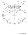
- Each of the bracelets shown in Figures 1 to 4 comprises two rigid arms 10 and 12 curved, a hinge 14 connecting them to each other by one of their ends identified by the letter a , and a head 16, movable and presented in the form of a housing inside which is housed a watch movement 18.
- the two arms 10 and 12 in the closed position, each embrace an angle of about 180 ° together forming a ring with an opening 20 for receiving the wrist of a carrier.
- Their connected ends 10a and 12a are provided with coaxial holes in which a pin AA axis is engaged to achieve a hinge 19 forming the hinge 14.
- These ends further comprise each a flat surface identified by the letter b which are coplanar.
- a protrusion identified by the letter c limits the surfaces 10b and 12b on their opposite side to the hinge 14.
- the head 16 is pivotally mounted at the end 10a of the arm 10, about an axis BB perpendicular to the surface 10b, by means of a tenon head 22 which is integral with it, engaged in a hole made in the end 10a of the arm 10, as can be seen in Figure 1a.
- the tenon 22 thus provides a means of connecting the arm 10 to the head 16.
- the latter comprises a flat lower face 16a, adjacent the surfaces 10b and 12b in the locked position and on which is fixed the pin 22, an upper surface 16b , convex, two lateral faces 16c and two wings 16d intended to cooperate with the protuberances 10c and 12c.
- the protuberances 10c and 12c, with the surfaces 10b and 12b form crampons and the two wings 16d latches each cooperating with one of the crampons, so as to make the head 16 and the arms 10 and 12 integral.
- the crampons and the locks respectively form the first and second parts of the connecting means of the arms 10 and 12 with the head 16.
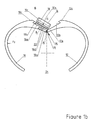
- these connecting means are both triggered when the head 16 is in the position shown in Figure 1b.
- the head 16 In the locked position of the head, shown in Figure 1a, the head 16 is in the general shape of the bracelet, the upper surface 16b extending the arms 10 and 12 and the hinge 19 being covered.
- a force F 1 on one of the side faces 16c substantially perpendicular to the plane of the drawing, and which pivots the head 16 and the pin 22 on the arm 10 , so that the wings 16d are disengaged from the protuberances 10c and 12c.
- the rotation should be about 90 °.
- the head then reaches its unlocked position.
- the force F 3 is perpendicular to F 1 and substantially parallel to the axis BB when it is the surface 12b and the face 16a which form the second connecting means, while it is substantially perpendicular to the axis BB in the another case, which is shown in Figure 1a.
- F 3 has the effect of generating a constraint at the post 22, but without causing a displacement of the head 16 with reference to the arms 10 and 12. The head 16 is thus locked and the arms 10 and 12 remain closed .
- the arms 10 and 12 can be opened only to the extent that the hinge 14 can freely work. This is possible only if the head 16, in the unlocked position, completely releases the surface 12b, and the hinge 19. The arm 12 is thus no longer limited in its movement by the face 16a. This condition is satisfied only if the distance between the axis B-B and the edge 16c is less than the distance between the axes A-A and B-B.
- the arms could also cooperate with a spring, as is done in the marquise watches, so that, during installation, the latter automatically take their closed position.
- the head 16 on the arm 10 removably. This is easily achieved by arranging the pin 22 and the hole in the arm 10 to form a bayonet engagement. In this case, the disengagement will be advantageously after an angle of rotation greater than 90 °, so that the risk of accidental detachment is removed.
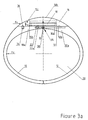
- FIG. 2 differs from that of Figure 1 by the symmetrical structure of the head 16 and its articulation 14.
- the other features are found in a similar manner, identified by the same references.
- the hinge 14 comprises a plate 26 connecting the two ends 10a and 12a and forming with them two hinges 28 and 30 pivoting about axes A-A and
- the plate 26 has a bearing surface 26a which, when the arms are in the closed position as shown in Figure 2a, is in the extension of the surfaces 10b and 12b.
- the surface 26a is of substantially square shape, with a side equal to or greater than the width of the head 16.
- the head 16 is pivotally mounted on the plate 26, about an axis BB perpendicular to the surface 26a and passing through its center, by means of a pin 22, similar in all respects to that used in the embodiment of the invention.
- FIG. 1. The pin 22 thus acts as a connecting means between the head 16 and the plate 26.
- the head 16 is symmetrical, it is possible to rotate it completely on the axis B-B. In this way, by arranging two movements of watches 18 in the head 16, displaying different times, it is possible to select the time displayed by simple rotation of the head.
- the head 16 In the locked position, shown in Figure 2a, the head 16 is in the general shape of the bracelet, the upper surface 16b extending the arms 10 and 12. To separate the head 16 and the arms 10 and 12, it is necessary to apply a force F 1 , substantially perpendicular to the plane of the drawing, on one of the side faces 16c, which pivots the head 16 and the pin 22 on the plate 26, so that the wings 16d separate from the protuberances 10c and 12c. The rotation should be about 90 °. The head then reaches its unlocked position.
- the surfaces 10b and 12b cooperating with the face 16a or the protuberances 10c and 12c with the wings 16d thus form means for connecting the head with the arms 10 and 12.
- the two connecting means of the head and the arms are triggered in the unlocked position, the permanent link function being provided by the pin 22 mounted on the plate 26.
- the arms 10 and 12 can be opened only to the extent that the hinge 14 can freely work. This is possible only if the head 16, in the unlocked position, completely releases the surfaces 10b and 12b, which are no longer limited in their movement by the face 16a. This condition is satisfied only if the distance between the axis BB and the edge 16c is less than the distance between BB and the axes AA and A'-A '.
- the head 16 of the bracelet described with reference to Figure 2 being symmetrical, it can occupy two locking positions, passing from one to the other by a rotation of 180 °. If it is provided with two movements of watches 18 and, as a result of a dual display of the time, it allows the display of two pieces of information, for example the hours of two time zones, the passage from one to the other. other being done by a simple rotation of the head 16.
- the head 16 can be removably mounted on the plate 26 by means of a bayonet assembly.
- FIGS. 1 and 2 show a different strap of the two examples described above because the head 16 is slidably mounted on the bearing surfaces 10b and 12b.
- the hinge 14 is identical to that of Figure 1, formed of two coaxial hinges 30, axis A-A, only one being visible in the drawing, separated by a space.
- the same parts bear the same references as in FIGS. 1 and 2.
- the head 16 comprises, as in the two examples described above, a flat lower face 16a, adjacent the surfaces 10b and 12b in the locked position and on which is fixed the pin 22, an upper surface 16b, convex, two side faces 16c .
- the upper surface 16b joins the lower face 16a at each end, so that the head 16 has a section having a cylindrical segment shape, of axis parallel to the axis A-A.
- the surfaces 10b and 12b comprise a groove 32, perpendicular to the axis AA and T-section, serving as a slide.
- the post 22 is provided with a protruding portion 22a, engaged in the groove 32 to form a slider and thus provide a connecting function between the head 16 and the arm 10.
- a spring ball 34 is housed in the arm 10 and protrudes from the surface 10b near its end opposite to the articulation 14.
- a conical hole 36 is formed in the face 16a, arranged so that the ball 34 It houses there when the head 16 is in the locked position.
- the head 16 In the locked position of the head, shown in Figure 3a, the head 16 is in the general shape of the bracelet, the upper surface 16b extending the arms 10 and 12.
- the pin 22 is engaged in the portion of the groove 32 associated the arm 10.
- the head 16 is held in this position by the engagement of the ball 34 in the conical hole 36.
- the arms 10 and 12 can be opened only to the extent that the hinge 14 can freely work. This is only possible if the head 16 completely releases the surface 10b and the hinges 30 in the unlocked position. The arm 10 is then no longer limited in its movement by the face 16a. This condition is satisfied only if the length of the groove 32 is at least equal to the distance between the hinge 14 and the end of the face 16a, the side where the force F 1 is applied.
- the hinge forming the hinge 14 it would also be possible to shift the hinge forming the hinge 14, so that the groove 32 is made only in the arm 12.
- the surface 10b is smaller than the surface 12b.
- the movement of the head 16 to move from one to the other of the locked and unlocked positions is reduced.
- connection means of the arm 12 with the head 16 remain engaged both in the locked and unlatched position of the head 16.
- the head 16 is pivotally mounted on the end 12a of the arm 12, about an axis CC parallel to the AA axis, by means of a hinge 36.
- the latter provides a function of connecting means between the arm 12 and the head 16, which comprises a flat lower face 16a, adjacent the surfaces 10b and 12b in the locked position, a surface upper 16b, curved, two side faces 16c, a first flange 16d intended to cooperate with the protuberance 10c and a second flange 16e arranged to form the hinge 36 with the protrusion 12c.
- the protuberance 10c forms a crampon and the wing 16d a latch, which cooperate with each other so as to make the head 16 and the arms 10 and 12 integral, the wing 16d being engaged notch in the protuberance 10c. and thus providing a function of connecting means between the head 16 and the arm 10.
- This notch can be achieved by a slight overlap of the wing 16d by the protrusion 10c, the arms 10 and 12 being sufficiently elastic to allow the necessary deformation at the release of the head 16. It is also possible to perform this function by means of a spring ball similar to that mentioned with reference to FIG. 3.
- the hinge 36 acts as a connecting means between the arm 12 and the head 16.
- the head 16 In the locked position of the head, shown in Figure 4a, the head 16 is in the general shape of the bracelet, the upper surface 16b extending the arms 10 and 12.
- both the arms 10 and 12 and the head 16 can be considerably changed. It is thus not necessary for the surfaces 10b, 12b and 16a to be flat. They could also be spherical in the first two embodiments, cylindrical in the third and of any shape in the fourth.
- the head could wear a cabochon or a cut stone, rather than being provided with a watch movement. It would also be possible to fix the movement in one of the arms of the bracelet and to be partially masked or not. If the display is hidden, the reading would be done by moving the head 16, but without bringing the latter to its unlocked position, to avoid inadvertent opening of the bracelet.
- the movement 18 could be housed in the arm 12 and the head 16 surround the housing of the movement 18 to form a telescope.
- the two arms 10 and 12 can embrace an angle of less than 180 °.
- the ends 10a and 12a will be arranged to form a stop when the arms are in the closed position.
Landscapes
- Physics & Mathematics (AREA)
- General Physics & Mathematics (AREA)
- Adornments (AREA)
- Buckles (AREA)
- Professional, Industrial, Or Sporting Protective Garments (AREA)
- Orthopedics, Nursing, And Contraception (AREA)
- Pivots And Pivotal Connections (AREA)
- Control And Other Processes For Unpacking Of Materials (AREA)
- Centrifugal Separators (AREA)
Abstract
Description
La présente invention se rapporte à un anneau articulé. Le terme d'anneau est à prendre dans un sens élargi, soit un objet de forme annulaire et susceptible d'être fixé sur un organe de forme générale cylindrique. Cet organe peut être un poignet, l'anneau étant un bracelet, mais également un cou, l'anneau étant alors un collier, ou un doigt, au quel cas il s'agira d'une bague.The present invention relates to an articulated ring. The term ring is to be taken in a wider sense, an object of annular shape and capable of being fixed on a body of generally cylindrical shape. This organ can be a wrist, the ring being a bracelet, but also a neck, the ring then being a collar, or a finger, in which case it will be a ring.
Cette invention concerne plus particulièrement un anneau du type comportant deux bras rigides incurvés et une articulation les reliant, mobiles, l'un en regard de l'autre à la première de leurs deux extrémités. Cet anneau est agencé de manière à pouvoir occuper deux positions, l'une ouverte dans laquelle les secondes extrémités sont écartées, de telle sorte que l'organe du porteur peut être glissé dans ou retiré de l'anneau par l'espace qui les sépare, l'autre fermée, dans laquelle l'espace entre les secondes extrémités est réduit, les bras entourant l'organe du porteur.This invention relates more particularly to a ring of the type comprising two curved rigid arms and an articulation linking them, movable, one facing each other at the first of their two ends. This ring is arranged so as to occupy two positions, one open in which the second ends are spaced apart, so that the body of the wearer can be slipped into or removed from the ring by the space between them the other closed, in which the space between the second ends is reduced, the arms surrounding the body of the wearer.
Ce genre d'anneaux est notamment utilisé dans les montres-bracelet, lesquelles sont connues sous le nom de "marquise". Le fait que les bras soient rigides offre des possibilités esthétiques originales. Dans ce type de montres, les deux bras sont maintenus au moyen d'un ressort qui tend à les rapprocher. La force d'armage du ressort joue un rôle important. Si elle est trop faible, il y a risque de perdre la montre, par ouverture intempestive des bras. Si elle est trop forte, il est mal aisé d'enlever la montre du poignet.This kind of rings is particularly used in wristwatches, which are known as "marquise". The fact that the arms are rigid offers original aesthetic possibilities. In this type of watch, the two arms are held by means of a spring that tends to bring them closer together. The winding force of the spring plays an important role. If it is too weak, there is a risk of losing the watch, by untimely opening of the arms. If it is too strong, it is not easy to remove the watch from the wrist.
Le document FR-A-940 506 se propose de pallier cet inconvénient. Il se rapporte à une montre qui comporte :
- deux bras rigides incurvés et une articulation les reliant mobiles l'un en regard de l'autre à la première de leurs deux extrémités,
- une tête, monté pivotant sur l'un des bras, et
- un verrou monté pivotant sur l'autre bras et coopérant avec la tête pour définir une position bloquée de la tête et des bras.
- two curved rigid arms and an articulating joint connecting them facing each other at the first of their two ends,
- a head, pivoted on one of the arms, and
- a latch pivotally mounted on the other arm and cooperating with the head to define a locked position of the head and arms.
Avec une telle solution, le risque de décrochement intempestif est non négligeable, par accrochage du verrou par exemple. De plus, le grand nombre d'articulations peut conduire à l'apparition d'ébats qui affectent le confort voire la sécurité du porter.With such a solution, the risk of inadvertent detachment is not negligible, for example by latching the latch. In addition, the large number of joints can lead to the appearance of frolics that affect the comfort or safety of wearing.
De manière plus précise, selon l'invention l'anneau est du type destiné à être disposé sur un organe d'un porteur et comporte :
- deux bras rigides incurvés et une articulation les reliant mobiles l'un en regard de l'autre à la première de leurs deux extrémités,
- une tête disposée au voisinage de l'articulation et agencée de manière à pouvoir occuper une première position, dite de verrouillage, et une seconde position dite de déverrouillage, et
- des premiers et deuxièmes moyens de liaison pour solidariser la tête avec respectivement le premier et le second bras, ces moyens de liaison étant tous les deux enclenchés lorsque la tête est en position de verrouillage et au moins les premiers de ces moyens étant déclenchés lorsque la tête est en position déverrouillée.
- two curved rigid arms and an articulating joint connecting them facing each other at the first of their two ends,
- a head disposed in the vicinity of the articulation and arranged so as to occupy a first position, called a locking position, and a second position called unlocking position, and
- first and second connecting means for securing the head with respectively the first and second arms, these connecting means being both engaged when the head is in the locking position and at least the first of these means being triggered when the head is in the unlocked position.
Les bras sont agencés pour occuper:
- une position ouverte dans laquelle leurs secondes extrémités sont écartées, de telle sorte que l'anneau peut être glissé sur ou retiré de l'organe du porteur par l'espace qui les sépare, et
- une position fermée dans laquelle cet espace est réduit, les bras entourant l'organe du porteur.
- an open position in which their second ends are spaced apart, so that the ring can be slipped on or removed from the wearer's organ by the space between them, and
- a closed position in which this space is reduced, the arms surrounding the body of the wearer.
Le but de la présente invention est de réaliser un anneau tel que défini ci-dessus, qui soit facile à mettre et à enlever, tout en garantissant une grande sécurité de porter et une bonne fiabilité. Ce but est atteint grâce au fait que les premiers moyens de liaison comportent des première et deuxième parties associées rigidement respectivement au premier bras et à la tête. En d'autres termes les première et deuxième parties des premiers moyens de liaison sont soit formé de matière avec le premier bras et la tête, soit rapportés et fixés rigidement sur ceux-ci, par soudure par exemple. Une telle structure garantit une bonne rigidité de l'ensemble, réduit le risque de décrochement intempestif et permet de nombreuses variantes du point de vue esthétique.The object of the present invention is to provide a ring as defined above, which is easy to put on and take off, while ensuring high wear safety and good reliability. This object is achieved thanks to the fact that the first connecting means comprise first and second parts rigidly associated respectively with the first arm and the head. In other words, the first and second parts of the first connecting means are either made of material with the first arm and the head, or are attached and fixed rigidly thereon, for example by welding. Such a structure ensures good rigidity of the assembly, reduces the risk of untimely setback and allows many variants from the aesthetic point of view.
Les première et deuxième parties des moyens de liaison sont avantageusement formées l'une d'un verrou et l'autre d'un crampon destinés à coopérer l'un avec l'autre lorsque la tête est en position verrouillée et désengagés l'un de l'autre lorsque la tête est en position déverrouillée.The first and second parts of the connecting means are advantageously formed one of a latch and the other of a crampon intended to cooperate with each other when the head is in the locked position and disengaged one of the other when the head is in the unlocked position.
Afin d'assurer un positionnement stable de la tête sur les bras, les premiers moyens de liaison sont agencés de manière à ce que le déplacement de la tête de sa position verrouillée à sa position déverrouillée se fasse par l'application d'une première force F1, et en ce qu'une force appliquée F2 sur l'un des bras lorsque la tête est en position verrouillée engendre sur cette dernière, par l'interaction du verrou et du crampon, une force résultante F3 sensiblement perpendiculaire à la première force F1, le tout de manière à ce que les bras restent en position fermée tant que la tête est en position verrouillée et peuvent être écartés l'un de l'autre lorsque la tête est en position déverrouillée.In order to ensure stable positioning of the head on the arms, the first connecting means are arranged in such a way that the movement of the head from its locked position to its unlocked position is effected by the application of a first force F 1 , and that an applied force F 2 on one of the arms when the head is in the locked position generates on the latter, by the interaction of the latch and the crampon, a resultant force F 3 substantially perpendicular to the first force F 1 , all so that the arms remain in the closed position as long as the head is in the locked position and can be moved apart when the head is in the unlocked position.
Afin de permettre de bonnes conditions de travail de l'articulation, celle-ci comporte au moins une charnière solidaire de l'un au moins des bras et qui définit un premier axe de pivotement, la charnière étant masquée lorsque la tête est en position verrouillée et découverte en position verrouillée.In order to allow good working conditions of the joint, the latter comprises at least one hinge integral with at least one of the arms and which defines a first axis of pivoting, the hinge being hidden when the head is in the locked position and discovery in locked position.
Dans un premier mode de réalisation, l'articulation comporte, en outre, une deuxième charnière pivotant autour d'un axe parallèle au premier axe, et une plaquette reliant la première à la deuxième charnière, l'une des charnières étant solidaire de l'un des bras, l'autre de l'autre bras.In a first embodiment, the hinge comprises, in addition, a second hinge pivoting about an axis parallel to the first axis, and a plate connecting the first to the second hinge, one of the hinges being secured to the hinge. one of the arms, the other of the other arm.
Dans un deuxième mode de réalisation, la tête est agencée de manière à pouvoir passer de l'une à l'autre des positions de verrouillage et de déverrouillage par coulissement dans l'un au moins des bras.In a second embodiment, the head is arranged so as to be able to move from one to the other of the locking and unlocking positions by sliding in at least one of the arms.
Afin d'assurer un bon positionnement de la tête en référence aux bras, dans la position verrouillée, l'anneau comporte, en outre, des moyens de positionnement à cran agencés pour coopérer d'une part avec la tête, d'autre part avec l'un des bras.In order to ensure proper positioning of the head with reference to the arms, in the locked position, the ring furthermore includes notch positioning means arranged to cooperate on the one hand with the head, on the other hand with one of the arms.
Selon un troisième mode de réalisation, la tête est agencée pour passer de l'une à l'autre des positions de verrouillage et de déverrouillage par rotation autour d'un deuxième axe perpendiculaire au premier axe.According to a third embodiment, the head is arranged to move from one to the other of the locking and unlocking positions by rotation about a second axis perpendicular to the first axis.
De manière avantageuse, au moins l'un des bras du bracelet comporte une protubérance et la tête une aile, la protubérance et l'aile formant l'un le verrou, l'autre le crampon.Advantageously, at least one of the arms of the bracelet has a protuberance and the head a wing, the protuberance and the wing forming one the latch, the other the crampon.
Dans un quatrième mode de réalisation, la tête est montée pivotante sur l'un des bras par l'une de ses extrémités, autour d'un troisième axe parallèle au premier axe et coopère par l'autre extrémité avec l'autre bras pour former un assemblage à cran.In a fourth embodiment, the head is pivotally mounted on one of the arms by one of its ends, around a third axis parallel to the first axis and cooperates by the other end with the other arm to form a notch assembly.
L'anneau peut avantageusement être utilisé comme montre bracelet. Une solution particulièrement intéressante consiste à disposer, dans la tête, un dispositif horaire muni de deux affichages distincts, les moyens de liaison étant agencés de manière à ce que la tête puisse occuper deux positions de verrouillage et que les affichages soient respectivement visibles dans la première et dans la deuxième de ces positions.The ring can advantageously be used as a wristwatch. A particularly interesting solution consists in arranging, in the head, a time device provided with two distinct displays, the connecting means being arranged in such a way that the head can occupy two locking positions and that the displays are respectively visible in the first one. and in the second of these positions.
D'autres avantages et caractéristiques de l'invention ressortiront de la description qui va suivre, faite en regard du dessin annexé, dans lequel les figures 1 à 4 représentent, vus de côté, quatre modes de réalisation d'un bracelet selon l'invention, en position verrouillée de la tête en a, bras ouverts et tête en position déverrouillée en b.Other advantages and characteristics of the invention will emerge from the description which follows, made with reference to the accompanying drawing, in which Figures 1 to 4 show, seen from the side, four embodiments of a bracelet according to the invention. , in the locked position of the head at a , arms open and head in the unlocked position at b .
Tous les modes de réalisation de l'invention décrits ci-après se rapportent donc à un bracelet muni d'une boîte dans laquelle est logé un mouvement de montre. Les moyens techniques mis en oeuvre peuvent sans autre être appliqués à un collier ou à une bague, moyennant une adaptation d'échelle. La présence d'un mouvement de montre ne joue pas non plus un rôle essentiel.All embodiments of the invention described below therefore relate to a bracelet provided with a box in which is housed a watch movement. The technical means used can not be applied to a collar or a ring, with scale adaptation. The presence of a watch movement does not play a vital role either.
Chacun des bracelets représentés aux figures 1 à 4 comprend deux bras rigides 10 et 12 incurvés, une articulation 14 les reliant l'un à l'autre par une de leurs extrémités identifiée par la lettre a, et une tête 16, mobile et se présentant sous forme d'un boîtier à l'intérieur duquel est logé un mouvement de montre 18.Each of the bracelets shown in Figures 1 to 4 comprises two
Sur la figure 1, les deux bras 10 et 12, en position fermée, embrassent chacun un angle d'environ 180°, formant ensemble un anneau avec une ouverture 20 destinée à recevoir le poignet d'un porteur. Leurs extrémités reliées 10a et 12a sont munies de trous coaxiaux dans lesquelles une goupille d'axe A-A est engagée pour réaliser une charnière 19 formant l'articulation 14. Ces extrémités comportent, en outre, chacune une surface plane identifiée par la lettre b lesquelles sont coplanaires. Une protubérance identifiée par la lettre c, limite les surfaces 10b et 12b sur leur côté opposé à l'articulation 14.In Figure 1, the two
La tête 16 est montée pivotante à l'extrémité 10a du bras 10, autour d'un axe B-B perpendiculaire à la surface 10b, au moyen d'un tenon à tête 22 qui lui est solidaire, engagé dans un trou pratiqué dans l'extrémité 10a du bras 10, comme on peut le voir sur la figure 1a. Le tenon 22 assure ainsi une fonction de moyen de liaison du bras 10 à la tête 16. Cette dernière comprend une face inférieure plane 16a, attenante aux surfaces 10b et 12b en position verrouillée et sur laquelle est fixé le tenon 22, une surface supérieure 16b, bombée, deux faces latérales 16c et deux ailes 16d destinées à coopérer avec les protubérances 10c et 12c.The
Plus précisément, les protubérances 10c et 12c, avec les surfaces 10b et 12b forment des crampons et les deux ailes 16d des verrous coopérant chacun avec l'un des crampons, de manière à rendre solidaires la tête 16 et les bras 10 et 12. En d'autres termes, les crampons et les verrous forment respectivement les premières et deuxièmes parties des moyens de liaison des bras 10 et 12 avec la tête 16. Dans ce mode de réalisation, ces moyens de liaison sont tous les deux déclenchés lorsque la tête 16 se trouve dans la position représentée sur la figure 1b.More specifically, the
En position verrouillée de la tête, représentée sur la figure 1a, la tête 16 s'inscrit dans la forme générale du bracelet, la surface supérieure 16b prolongeant les bras 10 et 12 et la charnière 19 étant couverte. Pour désolidariser la tête 16 et les bras 10 et 12, il faut appliquer une force F1 sur l'une des faces latérales 16c, sensiblement perpendiculaire au plan du dessin, et qui fait pivoter la tête 16 et le tenon 22 sur le bras 10, de telle sorte que les ailes 16d se désolidarisent des protubérances 10c et 12c. La rotation doit être de 90° environ. La tête atteint alors sa position déverrouillée.In the locked position of the head, shown in Figure 1a, the
Dans cette position, l'application, dans la partie médiane des bras 10 et 12, d'une force F2 inscrite dans un plan perpendiculaire à l'axe A-A et orientée vers l'extérieur, de manière à engendrer un couple par rapport à cet axe, provoque l'écartement des bras 10 et 12, formant entre eux, un espace 24 allant croissant jusqu'à atteindre la position ouverte représentée sur la figure 1b, dans laquelle il est possible de retirer ou d'introduire le poignet du porteur.In this position, the application, in the median part of the
Si, par contre, en position fermée des bras et en position verrouillée de la tête, on applique la force F2, cette force engendre une force résultant F3 appliquée soit par les surfaces 10b et 12b sur la face 16a, soit par les protubérances 10c et 12c sur les ailes 16d. La surface 12b et la face 16a ou la protubérance 10c et l'aile 16d avec laquelle elle coopère, forment ainsi des deuxièmes moyens de liaison solidarisant la tête avec le bras 10, mais uniquement lorsque la tête est en position verrouillée.If, on the other hand, in the closed position of the arms and in the locked position of the head, the force F 2 is applied, this force generates a resultant force F 3 applied either by the
La force F3 est perpendiculaire à F1 et sensiblement parallèle à l'axe B-B lorsque ce sont la surface 12b et la face 16a qui forment les deuxièmes moyens de liaison, alors qu'elle est sensiblement perpendiculaire à l'axe B-B dans l'autre cas, qui est représenté sur la figure 1a. F3 a pour effet d'engendrer une contrainte au niveau du tenon 22, mais sans pour autant provoquer un déplacement de la tête 16 en référence aux bras 10 et 12. La tête 16 est donc ainsi verrouillée et les bras 10 et 12 restent fermés.The force F 3 is perpendicular to F 1 and substantially parallel to the axis BB when it is the
Lorsque les bras se trouvent en position ouverte, la tête 16 étant en position déverrouillée, comme représenté sur la figure 1b, il suffit d'appliquer sur les bras 10 et 12 une force contraire à F2 jusqu'à avoir les bras 10 et 12 en position fermée, les extrémités libres des bras 10 et 12 formant butée. Dans cette position, les surfaces 10b et 12b sont, à nouveau, coplanaires, de telle sorte qu'en appliquant, sur l'autre face latérale 16c, une force de sens contraire à F1, celle-ci ramène la tête 16 dans sa position verrouillée.When the arms are in the open position, the
Il est bien évident que les bras 10 et 12 ne peuvent être ouverts que dans la mesure où l'articulation 14 peut librement travailler. Cela n'est possible que si la tête 16, en position déverrouillée, dégage complètement la surface 12b, et la charnière 19. Le bras 12 n'est ainsi plus limité dans son mouvement par la face 16a. Cette condition n'est satisfaite que si la distance entre l'axe B-B et le bord 16c est inférieure à la distance comprise entre les axes A-A et B-B.It is obvious that the
Dans une variante qui n'a pas été représentée, les bras pourraient aussi coopérer avec un ressort, comme cela se fait dans les montres marquises, de telle sorte que, lors de la mise en place, ces derniers prennent automatiquement leur position fermée.In a variant that has not been shown, the arms could also cooperate with a spring, as is done in the marquise watches, so that, during installation, the latter automatically take their closed position.
Dans une autre variante, il est également possible de monter la tête 16 sur le bras 10 de manière amovible. Cela est facilement réalisable en agençant le tenon 22 et le trou pratiqué dans le bras 10 de manière à former un enclenchement à baïonnette. Dans ce cas, le désenclenchement se fera avantageusement après un angle de rotation supérieur à 90°, de manière à ce que le risque de décrochement accidentel soit écarté.In another variant, it is also possible to mount the
Le mode de réalisation représenté à la figure 2 diffère de celui de la figure 1 par la structure symétrique de la tête 16 et par son articulation 14. Les autres caractéristiques se retrouvent de manière similaire, identifiées par de mêmes références.The embodiment shown in Figure 2 differs from that of Figure 1 by the symmetrical structure of the
L'articulation 14 comporte une plaquette 26 reliant les deux extrémités 10a et 12a et formant avec elles deux charnières 28 et 30 pivotant autour d'axes A-A etThe
A'-A' parallèles entre eux.A'-A 'parallel to each other.
La plaquette 26 présente une surface d'appui 26a qui, lorsque les bras sont en position fermée telle que représentée sur la figure 2a, se trouve dans le prolongement des surfaces 10b et 12b. La surface 26a est de forme sensiblement carrée, de côté égal ou supérieur à la largeur de la tête 16.The
La tête 16 est montée pivotante sur la plaquette 26, autour d'un axe B-B perpendiculaire à la surface 26a et passant par son centre, au moyen d'un tenon 22, semblable en tous points à celui utilisé dans le mode de réalisation de la figure 1. Le tenon 22 assure ainsi une fonction de moyens de liaison entre la tête 16 et la plaquette 26.The
Comme la tête 16 est symétrique, il est possible de la faire tourner complètement sur l'axe B-B. De la sorte, en disposant deux mouvements de montres 18 dans la tête 16, affichant des heures différentes, il est possible de sélectionner l'heure affichée par simple rotation de la tête.As the
En position verrouillée, représentée sur la figure 2a, la tête 16 s'inscrit dans la forme générale du bracelet, la surface supérieure 16b prolongeant les bras 10 et 12. Pour désolidariser la tête 16 et les bras 10 et 12, il faut appliquer une force F1, sensiblement perpendiculaire au plan du dessin, sur l'une des faces latérales 16c, qui fait pivoter la tête 16 et le tenon 22 sur la plaquette 26, de telle sorte que les ailes 16d se désolidarisent des protubérances 10c et 12c. La rotation doit être de 90° environ. La tête atteint alors sa position déverrouillée. Dans cette position, où les deux charnières 28 et 30 sont découvertes, l'application, dans la partie médiane des bras 10 et 12, d'une force F2 inscrite dans un plan perpendiculaire aux axes A-A et A'-A', et orientée vers l'extérieur, de manière à engendrer un couple par rapport à ces axes, provoque l'écartement des bras 10 et 12 qui forment ainsi entre eux un espace 24 allant croissant jusqu'à atteindre la position ouverte représentée sur la figure 2b, dans laquelle il est possible de retirer ou d'introduire le poignet du porteur.In the locked position, shown in Figure 2a, the
Si, par contre, en position fermée des bras et en position verrouillée de la tête 16, on applique la force F2, cette force engendre une force résultant F3 appliquée soit par les surfaces 10b et 12b sur la face 16a, comme représenté sur la figure 2a, soit par les protubérances 10c et 12c sur les ailes 16d.If, on the other hand, in the closed position of the arms and in the locked position of the
Les surfaces 10b et 12b coopérant avec la face 16a ou les protubérances 10c et 12c avec les ailes 16d forment ainsi des moyens de liaison de la tête avec les bras 10 et 12. Dans ce cas, les deux moyens de liaison de la tête et des bras sont déclenchés en position déverrouillée, la fonction de liaison permanente étant assurée par le tenon 22 monté sur la plaquette 26.The
Lorsque ce sont les surfaces 10b et 12b qui engendrent la force résultante F3, celle-ci est alors sensiblement perpendiculaire à F1 et à F2 et parallèle à l'axe B-B, ce qui a pour effet de produire une contrainte au niveau du tenon 22, mais sans pour autant provoquer un déplacement de la tête 16 en référence aux bras 10 et 12. La tête 16 est donc ainsi verrouillée et les bras 10 et 12 restent fermés.When it is the
Lorsque les bras se trouvent en position ouverte, la tête 16 étant en position déverrouillée, comme représenté sur la figure 2b, il suffit d'appliquer sur les bras 10 et 12 une force contraire à F2 jusqu'à avoir les bras 10 et 12 en position fermée, les extrémités libres des bras 10 et 12 formant butée. Dans cette position, les surfaces 10b et 12b sont, à nouveau, coplanaires, de telle sorte qu'en appliquant, sur l'autre face latérale 16c, une force de sens contraire à F1, celle-ci ramène la tête 16 dans sa position verrouillée.When the arms are in the open position, the
Il est bien évident que les bras 10 et 12 ne peuvent être ouverts que dans la mesure où l'articulation 14 peut librement travailler. Cela n'est possible que si la tête 16, en position déverrouillée, dégage complètement les surfaces 10b et 12b, lesquelles ne sont plus limitées dans leur mouvement par la face 16a. Cette condition n'est satisfaite que si la distance entre l'axe B-B et le bord 16c est inférieure à la distance comprise entre B-B et les axes A-A et A'-A'.It is obvious that the
La tête 16 du bracelet décrit en référence à la figure 2 étant symétrique, elle peut occuper deux positions de verrouillage, en passant de l'une à l'autre par une rotation de 180°. Si elle est munie de deux mouvements de montres 18 et, en conséquence d'un double affichage de l'heure, elle permet l'affichage de deux informations, par exemple les heures de deux fuseaux horaires, le passage de l'une à l'autre se faisant par une simple rotation de la tête 16.The
Dans ce cas également, la tête 16 peut être montée amovible sur la plaquette 26 au moyen d'un assemblage à baïonnette.In this case also, the
La figure 3 représente un bracelet différent des deux exemples décrits précédemment du fait que la tête 16 est montée coulissante sur les surfaces d'appui 10b et 12b. Dans cette configuration, l'articulation 14 est identique à celle de la figure 1, formée de deux charnières coaxiales 30, d'axe A-A, l'une seulement étant visible au dessin, séparées par un espace. Sur cette figure également, les mêmes parties portent les mêmes références que sur les figures 1 et 2.3 shows a different strap of the two examples described above because the
La tête 16 comporte, comme dans les deux exemples décrits ci-dessus, une face inférieure plane 16a, attenante aux surfaces 10b et 12b en position verrouillée et sur laquelle est fixé le tenon 22, une surface supérieure 16b, bombée, deux faces latérales 16c. Dans ce cas, toutefois, la surface supérieure 16b rejoint la face inférieure 16a à chacune des extrémités, de sorte que la tête 16 a une section présentant une forme de segment de cylindre, d'axe parallèle à l'axe A-A.The
De manière plus précise, les surfaces 10b et 12b comportent une gorge 32, perpendiculaire à l'axe A-A et de section en T, servant de coulisse. Le tenon 22 est muni d'une portion faisant saillie 22a, engagée dans la gorge 32 pour former un coulisseau et assurer ainsi une fonction de liaison entre la tête 16 et le bras 10.More specifically, the
Une bille à ressort 34 est logée dans le bras 10 et dépasse de la surface 10b au voisinage de son extrémité opposée à l'articulation 14. Un trou conique 36 est pratiqué dans la face 16a, disposé de manière à ce que la bille 34 s'y loge lorsque la tête 16 est en position verrouillée.A
En position verrouillée de la tête, représentée sur la figure 3a, la tête 16 s'inscrit dans la forme générale du bracelet, la surface supérieure 16b prolongeant les bras 10 et 12. Le tenon 22 est engagé dans la partie de la gorge 32 associée au bras 10. La tête 16 est maintenue dans cette position par l'engagement de la bille 34 dans le trou conique 36.In the locked position of the head, shown in Figure 3a, the
Pour désolidariser la tête 16 et les bras 10 et 12, il faut appliquer une force F1 sur la face supérieure 16b, sensiblement orientée parallèlement à la gorge 32 et inscrite dans le plan du dessin. Cette force F1 vainc la force de positionnement de la bille 34 et provoque le coulissement de la tête 16, jusqu'à ce que le tenon 22 atteigne l'autre extrémité de la gorge 32, ce qui correspond à la position déverrouillée de la tête 16.To disengage the
Dans cette position, l'application, dans la partie médiane des bras 10 et 12, d'une force F2 inscrite dans un plan perpendiculaire à l'axe A-A et orientée vers l'extérieur, de manière à engendrer un couple par rapport à cet axe, provoque l'écartement des bras 10 et 12, formant entre eux, un espace 24 allant croissant jusqu'à atteindre la position ouverte représentée sur la figure 3b, dans laquelle il est possible de retirer ou d'introduire le poignet du porteur.In this position, the application, in the median part of the
Si, par contre, en position fermée des bras et en position verrouillée de la tête 12, on applique la force F2, cette force engendre une force résultant F3 perpendiculaire à F1, appliquée par les surfaces 10b et 12b sur la face 16a , ce qui a pour effet d'engendrer une contrainte au niveau du tenon 22, mais sans pour autant provoquer un déplacement de la tête 16 en référence aux bras 10 et 12. Les surfaces 10b et 12b avec la face 16a assurent ainsi des fonctions de moyens de liaison entre la tête 16 et le bras 12. La tête 16 est donc ainsi verrouillée et les bras 10 et 12 restent fermés, la tête 16 tenant lieu de verrou et les bras 10 et 12 de crampon.If, on the other hand, in the closed position of the arms and in the locked position of the
Lorsque les bras se trouvent en position ouverte, la tête 16 étant en position déverrouillée, comme représenté sur la figure 3b, il suffit d'appliquer sur les bras 10 et 12 une force contraire à F2 jusqu'à avoir les bras 10 et 12 en position fermée, les extrémités libres des bras 10 et 12 formant butée. Dans cette position, les surfaces 10b et 12b sont, à nouveau, coplanaires, de telle sorte qu'en appliquant, sur l'autre côté de la face supérieure 16a une force de sens contraire à F1, elle ramène la tête 16 dans sa position verrouillée.When the arms are in the open position, the
Il est bien évident que les bras 10 et 12 ne peuvent être ouverts que dans la mesure où l'articulation 14 peut librement travailler. Cela n'est possible que si la tête 16 dégage complètement la surface 10b et les charnières 30 en position déverrouillée. Le bras 10 n'est alors plus limité dans son mouvement par la face 16a. Cette condition n'est satisfaite que si la longueur de la gorge 32 est au moins égale à la distance comprise entre l'articulation 14 et l'extrémité de la face 16a, du côté où la force F1 est appliquée.It is obvious that the
Dans une variante qui n'a pas été représentée, il est possible de retirer la tête 16 du bracelet en agençant la saillie 22a de manière à ce qu'en tournant la tête 16 lorsqu'elle se trouve en position déverrouillée, elle puisse être retirée de la gorge 32.In a variant that has not been shown, it is possible to remove the
Dans ce mode de réalisation, il serait également possible de décaler la charnière formant l'articulation 14, de manière à ce que la gorge 32 ne soit pratiquée que dans le bras 12. Dans ce cas, la surface 10b est inférieure à la surface 12b. En outre, le déplacement de la tête 16, pour passer de l'une à l'autre des positions verrouillée et déverrouillée est ainsi réduit.In this embodiment, it would also be possible to shift the hinge forming the
On relèvera que dans le mode de réalisation de la figure 3, les moyens de liaison du bras 12 avec la tête 16 restent enclenchés aussi bien en position verrouillée que déverrouillée de la tête 16.It will be noted that in the embodiment of FIG. 3, the connection means of the
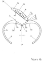
Dans le mode de réalisation de la figure 4, à propos duquel les parties communes aux autres modes de réalisation portent les mêmes références, la tête 16 est montée pivotante sur l'extrémité 12a du bras 12, autour d'un axe C-C parallèle à l'axe A-A, au moyen d'une charnière 36. Cette dernière assure une fonction de moyens de liaison entre le bras 12 et la tête 16, laquelle comprend une face inférieure plane 16a, attenante aux surfaces 10b et 12b en position verrouillée, une surface supérieure 16b, bombée, deux faces latérales 16c, une première aile 16d destinée à coopérer avec la protubérance 10c et une seconde aile 16e agencée pour former la charnière 36 avec la protubérance 12c.In the embodiment of Figure 4, in which the common parts of the other embodiments have the same references, the
La protubérance 10c forme un crampon et l'aile 16d un verrou, qui coopèrent l'un avec l'autre de manière à rendre solidaires la tête 16 et les bras 10 et 12, l'aile 16d étant engagée à cran dans la protubérance 10c et assurant ainsi une fonction de moyens de liaison entre la tête 16 et le bras 10. Ce cran peut être réalisé par un léger recouvrement de l'aile 16d par la protubérance 10c, les bras 10 et 12 étant suffisamment élastiques pour permettre la déformation nécessaire au dégagement de la tête 16. Il est aussi possible d'assurer cette fonction au moyen d'une bille à ressort similaire à celle mentionnée en référence à la figure 3. Par ailleurs, la charnière 36 assure la fonction de moyen de liaison entre le bras 12 et la tête 16.The
En position verrouillée de la tête, représentée sur la figure 4a, la tête 16 s'inscrit dans la forme générale du bracelet, la surface supérieure 16b prolongeant les bras 10 et 12.In the locked position of the head, shown in Figure 4a, the
Pour désolidariser la tête 16 et les bras 10 et 12, il faut appliquer une force F1 orientée vers le haut, en saisissant la tête 16 par ses faces latérales 16c. F1 fait pivoter la tête 16 sur le bras 12, grâce à la charnière 36, de telle sorte que l'aile 16d se désolidarise de la protubérance 10c. Dès que l'aile 16d est dégagée de la protubérance 10c, la tête est déverrouillée.To disengage the
Dans cette position, l'application, dans la partie médiane des bras 10 et 12, d'une force F2 inscrite dans un plan perpendiculaire à l'axe A-A et orientée vers l'extérieur, de manière à engendrer un couple par rapport à cet axe, provoque l'écartement des bras 10 et 12, formant entre eux, un espace 24 allant croissant jusqu'à atteindre la position ouverte représentée sur la figure 4b, dans laquelle il est possible de retirer ou d'introduire le poignet du porteur.In this position, the application, in the median part of the
Si, par contre, en position fermée des bras et en position verrouillée de la tête, on applique la force F2, cette force engendre une force résultant F3 par la protubérance 10c sur l'aile 16d. La force F3 est perpendiculaire à F1, ce qui a pour effet d'engendrer une contrainte au niveau de la charnière 36, mais sans pour autant provoquer un déplacement de la tête 16 en référence aux bras 10 et 12. La tête 16 est donc ainsi verrouillée et les bras 10 et 12 restent fermés.If, on the other hand, in the closed position of the arms and in the locked position of the head, the force F 2 is applied, this force generates a resultant force F 3 by the
Lorsque les bras se trouvent en position ouverte, la tête 16 étant en position déverrouillée, comme représenté sur la figure 4b, il suffit d'appliquer sur les bras 10 et 12 une force contraire à F2 jusqu'à avoir les bras 10 et 12 en position fermée, les extrémités libres des bras 10 et 12 formant butée. Dans cette position, les surfaces 10b et 12b sont, à nouveau, coplanaires, de telle sorte qu'en appliquant, sur la face supérieure 16b, une force de sens contraire à F1, elle ramène la tête 16 dans sa position verrouillée.When the arms are in the open position, the
Dans ce mode de réalisation, seul les premiers moyens de liaison, qui relient le bras 10 à la tête 16, sont déclenchés lorsque la tête est en position déverrouillée.In this embodiment, only the first connecting means, which connect the
Les quatre modes de réalisations décrits montrent que l'anneau selon l'invention peut faire l'objet de nombreuses variantes. D'autres encore sont envisageables, sans pour autant sortir du cadre de l'invention. Comme évoqué plus haut, il est possible de réaliser non seulement des bracelets, mais également des colliers ou des bagues, par exemple.The four described embodiments show that the ring according to the invention can be the subject of numerous variants. Still others are conceivable, without departing from the scope of the invention. As mentioned above, it is possible to make not only bracelets, but also necklaces or rings, for example.
Les formes tant des bras 10 et 12 que de la tête 16 peuvent être considérablement changées. Il n'est ainsi pas nécessaire que les surfaces 10b, 12b et 16a soient planes. Elles pourraient aussi être sphériques dans les deux premiers modes de réalisation, cylindriques dans le troisième et de forme quelconque dans le quatrième.The shapes of both the
Dans un autre mode de réalisation qui n'a pas été représenté, la tête pourrait porter un cabochon ou une pierre taillée, plutôt que d'être munie d'un mouvement de montre. Il serait également possible de fixer le mouvement dans l'un des bras du bracelet et être ou non partiellement être masquée. Si l'affichage est masqué, la lecture se ferait en déplaçant la tête 16, mais sans amener cette dernière jusqu'à sa position déverrouillée, afin d'éviter une ouverture intempestive du bracelet.In another embodiment that has not been shown, the head could wear a cabochon or a cut stone, rather than being provided with a watch movement. It would also be possible to fix the movement in one of the arms of the bracelet and to be partially masked or not. If the display is hidden, the reading would be done by moving the
Dans la variante de la figure 4, le mouvement 18 pourrait être logé dans le bras 12 et la tête 16 entourer le logement du mouvement 18 pour former une lunette.In the variant of Figure 4, the
On relèvera enfin que les deux bras 10 et 12 peuvent embrasser un angle inférieur à 180°. Dans ce cas toutefois, les extrémités 10a et 12a seront agencées de manière à former butée lorsque les bras se trouvent en position fermée.It will finally be noted that the two
Il apparaît ainsi que, dans tous les modes de réalisation décrits, dans lesquels les moyens de liaison sont associés rigidement aux bras 10 et 12, et à la tête 16, il est possible de réaliser différentes variantes de bracelets offrant toutes des conditions d'assemblage sûres et des possibilités esthétiques particulièrement originales.It thus appears that, in all the embodiments described, in which the connecting means are rigidly associated with the
Claims (11)
- Ring, of the type intended to be arranged on a body part of a wearer and including:- two rigid bent arms (10, 12) and an articulation (14) connecting them, said arms being mobile facing each other at the first (10a, 12a) of their two ends,- a head part (16) arranged in proximity to the articulation (14) and arranged so as to be able to occupy a first position, called the locking position, and a second position, called the unlocking position, and- first and second connecting means for securing the head part respectively to the first and second arms, said means both being locked when the head part (16) is in the locked position and at least the first of said means being disengaged when the head part is in the unlocked positionarranged to occupy:- an open position in which their second ends are separated, such that the ring can be slipped onto or off the wearer's body part through the gap that separates them, and- a closed position in which this gap is reduced, the arms surrounding the wearer's body part,characterised in that the first connecting means include first and second parts rigidly associated respectively with the first arm and with the head part.
- Ring according to claim 1, characterised in that one of said first and second parts is formed of a locking portion (16d) and the other of a hook portion (10c), intended to co-operate with each other when the head part is in a locked position and disengaged from each other when the head part is in the unlocked position.
- Ring according to claim 2, characterised in that the first connecting means are arranged such that the movement of the head part (16) from its locked position to is unlocked position occurs by applying a first force F1, and in that a force F2 applied to one of the arms (10, 12) when the head part (16) is in the locked position, generates thereon, via the interaction of the locking portion (16d) and the hook portion (10c), a resulting force F3 substantially perpendicular to the first force F1, such that the arms (10, 12) remain in a closed position while the head part is in the locked position and can be separated from each other when the head part (16) is in the unlocked position.
- Ring according to claims 1 to 3, characterised in that said articulation (14) includes at least a hinge (19, 28) secured to at least one of said arms and which defines a first pivoting axis (A-A), said hinge being masked when the head part (16) is in the locked position and exposed in the locked position.
- Ring according to claim 4, characterised in that said articulation further includes a second hinge (30) pivoting about a parallel axis to the first axis, and a plate (26) connecting the first hinge (28) to the second (30) hinge, one (28) of the hinges being secured to one of the arms (10), the other (30) to the other arm (12).
- Ring according to any of claims 1 to 4, characterised in that said head part (16) is arranged so as to be able to pass from one of the locking and unlocking positions to the other by sliding into at least one (12) of said arms.
- Ring according to claim 6, characterised in that it further includes positioning means (34) of the snap-fitting type arranged to co-operate on the one hand with said head part (16), and on the other hand with one of the arms (10), to guarantee the locked position of the head part with respect to the arms.
- Ring according to claim 4 or 5, characterised in that said head part is arranged to pass from one of the locking and unlocking positions to the other by rotating about a second axis (B-B) perpendicular to the first axis (A-A).
- Ring according to claim 8, characterised in that at least one of the arms (10) includes a protuberance (10c) and the head part (16) a wing (16d), one of said protuberance and wing forming said locking portion, and the other said hook portion.
- Ring according to claim 2 or 3, characterised in that said head part (16) is mounted so as to pivot on one of the arms (12) via one of its ends, about a third axis (C-C), parallel to the first axis (A-A) and co-operates via the other end with the other arm (10) to form a snap-fitting type assembly.
- Ring according to any of claims 1 to 10, characterised in that said connecting means are arranged such that said head part (16) can occupy two locking positions and is provided with a timekeeping device (18) including two distinct displays respectively visible in the first and in the second of said locking positions.
Priority Applications (1)
| Application Number | Priority Date | Filing Date | Title |
|---|---|---|---|
| EP02743505A EP1404190B1 (en) | 2001-07-11 | 2002-07-10 | Articulated open ring |
Applications Claiming Priority (4)
| Application Number | Priority Date | Filing Date | Title |
|---|---|---|---|
| EP01116879 | 2001-07-11 | ||
| EP01116879A EP1275319A1 (en) | 2001-07-11 | 2001-07-11 | Articulated open ring |
| PCT/IB2002/002706 WO2003005850A1 (en) | 2001-07-11 | 2002-07-10 | Articulated open ring |
| EP02743505A EP1404190B1 (en) | 2001-07-11 | 2002-07-10 | Articulated open ring |
Publications (2)
| Publication Number | Publication Date |
|---|---|
| EP1404190A1 EP1404190A1 (en) | 2004-04-07 |
| EP1404190B1 true EP1404190B1 (en) | 2006-10-11 |
Family
ID=8178015
Family Applications (2)
| Application Number | Title | Priority Date | Filing Date |
|---|---|---|---|
| EP01116879A Withdrawn EP1275319A1 (en) | 2001-07-11 | 2001-07-11 | Articulated open ring |
| EP02743505A Expired - Lifetime EP1404190B1 (en) | 2001-07-11 | 2002-07-10 | Articulated open ring |
Family Applications Before (1)
| Application Number | Title | Priority Date | Filing Date |
|---|---|---|---|
| EP01116879A Withdrawn EP1275319A1 (en) | 2001-07-11 | 2001-07-11 | Articulated open ring |
Country Status (9)
| Country | Link |
|---|---|
| US (1) | US7017368B2 (en) |
| EP (2) | EP1275319A1 (en) |
| JP (1) | JP2004533897A (en) |
| KR (1) | KR20040038978A (en) |
| CN (1) | CN1236713C (en) |
| AT (1) | ATE341959T1 (en) |
| DE (1) | DE60215349D1 (en) |
| TW (1) | TW582995B (en) |
| WO (1) | WO2003005850A1 (en) |
Families Citing this family (13)
| Publication number | Priority date | Publication date | Assignee | Title |
|---|---|---|---|---|
| KR20070111012A (en) * | 2006-05-16 | 2007-11-21 | 삼성전자주식회사 | Watch type mobile phone |
| US7799979B2 (en) * | 2008-11-20 | 2010-09-21 | Swartz Patrick Neil | Plectrum mounting apparatus and method of use |
| EP3575887A1 (en) * | 2011-10-05 | 2019-12-04 | Suunto Oy | Watch case and wrist watch device |
| US20140102136A1 (en) * | 2012-10-12 | 2014-04-17 | Michael K. Warren | Jewelry piece with interchangeable rfid tag |
| WO2014150717A2 (en) * | 2013-03-15 | 2014-09-25 | Himanshu Singh | Ring protection device |
| KR20160080821A (en) * | 2014-12-26 | 2016-07-08 | 쓰리엠 이노베이티브 프로퍼티즈 캄파니 | Buckle for adjusting the length of strap and respirator comprising the same |
| CN106963352A (en) * | 2017-04-24 | 2017-07-21 | 苏州国科智策智能科技有限公司 | The combination type intelligent health finger ring of pressure controllable |
| US11284685B2 (en) | 2017-08-09 | 2022-03-29 | Guaicaipuro Rodriguez Garcia | Openable finger ring system |
| KR102082209B1 (en) * | 2018-05-24 | 2020-02-27 | 이연서 | BRACELET USING cellulose ACETATE RECYCLING BLOCK |
| USD909230S1 (en) | 2018-10-23 | 2021-02-02 | Cecil James Pounder, III | Article of jewelry |
| US11087724B1 (en) * | 2018-11-08 | 2021-08-10 | Cole Eshee Heve McBride | Spring loaded thumb pick |
| US11800911B2 (en) | 2021-04-12 | 2023-10-31 | Steve Govea Suarez | Radial watch |
| CN113349528B (en) * | 2021-07-01 | 2022-12-02 | 深圳市纳晶云科技有限公司 | Intelligent watch capable of being worn and used by single hand |
Family Cites Families (19)
| Publication number | Priority date | Publication date | Assignee | Title |
|---|---|---|---|---|
| US1128084A (en) * | 1913-05-27 | 1915-02-09 | Charles S Wilcoxon | Ring. |
| FR940506A (en) * | 1947-01-23 | 1948-12-15 | Bracelet | |
| US3182876A (en) * | 1963-12-23 | 1965-05-11 | Ibm | Bursting device for multilayer webs |
| US3465543A (en) * | 1966-03-08 | 1969-09-09 | John T Baker | Openable finger ring with pivoted locking element |
| US3566616A (en) * | 1969-02-14 | 1971-03-02 | Robert A Benedict Jr | Ornamental finger ring having a separable connection in its band |
| US3736770A (en) * | 1971-02-26 | 1973-06-05 | J Kelrick | Adjustable ring having bridge element and firmly secured notched latch bar |
| US4236384A (en) * | 1978-09-01 | 1980-12-02 | Daub Arthur R | Locking assembly for article of jewelry |
| US4753087A (en) * | 1985-11-12 | 1988-06-28 | Annunzio Philip D | Adjustable ring structure |
| EP0313710B1 (en) * | 1987-10-26 | 1992-06-17 | Premiere De Tabbah Sa | Piece of jewellery |
| US4790148A (en) * | 1987-12-10 | 1988-12-13 | Gerard Faini | Ring shank |
| US4879883A (en) * | 1988-08-09 | 1989-11-14 | Bruner Mates A | Openable ring with unique locking and release means |
| GB8830050D0 (en) * | 1988-12-23 | 1989-02-22 | Creates Allan | Finger ring |
| US5136858A (en) * | 1991-05-03 | 1992-08-11 | Bruner Mates A | Openable ring with interleaving member |
| US5651273A (en) * | 1993-06-29 | 1997-07-29 | Davida Enterprises, Inc. | Hinged finger ring |
| US5816073A (en) * | 1997-02-11 | 1998-10-06 | Marquesa, Inc. | Hinged earring |
| US6085550A (en) * | 1998-02-09 | 2000-07-11 | Ishida; Mitsugi | Adjustable article of jewelry and related method |
| DK175003B1 (en) * | 1999-04-28 | 2004-04-19 | Daniel Bentley | Finger ring |
| US20020069670A1 (en) * | 2000-12-11 | 2002-06-13 | Edward Rosenberg | System for sizing and re-sizing articles of jewelry |
| US6568214B2 (en) * | 2001-03-16 | 2003-05-27 | Michael Wolff | Hinged ring that supports an ornament and a system and method for making same |
-
2001
- 2001-07-11 EP EP01116879A patent/EP1275319A1/en not_active Withdrawn
-
2002
- 2002-07-10 AT AT02743505T patent/ATE341959T1/en not_active IP Right Cessation
- 2002-07-10 CN CNB028130820A patent/CN1236713C/en not_active Expired - Fee Related
- 2002-07-10 EP EP02743505A patent/EP1404190B1/en not_active Expired - Lifetime
- 2002-07-10 WO PCT/IB2002/002706 patent/WO2003005850A1/en active IP Right Grant
- 2002-07-10 DE DE60215349T patent/DE60215349D1/en not_active Expired - Lifetime
- 2002-07-10 US US10/480,711 patent/US7017368B2/en not_active Expired - Fee Related
- 2002-07-10 KR KR10-2004-7000342A patent/KR20040038978A/en not_active Application Discontinuation
- 2002-07-10 JP JP2003511664A patent/JP2004533897A/en not_active Abandoned
- 2002-10-25 TW TW091125014A patent/TW582995B/en not_active IP Right Cessation
Also Published As
| Publication number | Publication date |
|---|---|
| EP1275319A1 (en) | 2003-01-15 |
| US7017368B2 (en) | 2006-03-28 |
| JP2004533897A (en) | 2004-11-11 |
| EP1404190A1 (en) | 2004-04-07 |
| CN1522117A (en) | 2004-08-18 |
| TW582995B (en) | 2004-04-11 |
| ATE341959T1 (en) | 2006-11-15 |
| DE60215349D1 (en) | 2006-11-23 |
| WO2003005850A1 (en) | 2003-01-23 |
| KR20040038978A (en) | 2004-05-08 |
| US20040172968A1 (en) | 2004-09-09 |
| CN1236713C (en) | 2006-01-18 |
Similar Documents
| Publication | Publication Date | Title |
|---|---|---|
| EP1404190B1 (en) | Articulated open ring | |
| EP1875826B1 (en) | Item of jewellery with a movable element | |
| EP2188676A1 (en) | Wrist watch including a reversibility device | |
| EP3414630B1 (en) | Reversible wristwatch having multiple configurations | |
| EP0865742B1 (en) | Foldable fastener for a bracelet | |
| EP1437635B1 (en) | Watch case | |
| EP3709103B1 (en) | Device for blocking a rotating bezel | |
| EP3928652B1 (en) | Locking device for a bracelet clasp | |
| CH715870B1 (en) | Fastening system for bracelets. | |
| EP1971236B1 (en) | Extensible device for watch strap | |
| EP3957205A1 (en) | Timepiece component provided with a cover | |
| EP2120625B1 (en) | Watch bracelet | |
| CH716815B1 (en) | Article of jewelery comprising a clasp. | |
| WO2010108297A1 (en) | Ornamental item | |
| CH709653B1 (en) | Articulated assembly and spectacle frame comprising such an assembly. | |
| CH712115A2 (en) | Wristwatch whose bracelet can be removed without tools. | |
| CH713974A2 (en) | Mechanical connecting device for watchmaking components, in particular in the form of a fixing bar. | |
| EP0079891A1 (en) | Watch provided with a link member | |
| FR2743641A1 (en) | Wristwatch bracelet attachment apparatus | |
| WO2023078836A1 (en) | Joining of a strap strand to a watch case | |
| CH716020B1 (en) | Timepiece comprising a bezel with an elastic attachment. | |
| EP3918946A1 (en) | Device for attaching a strap to a watch case | |
| EP4238447A1 (en) | Folding buckle clasp | |
| CH708488A2 (en) | An screwless hinge joint or central axis through. | |
| EP3955066A1 (en) | Watch comprising a control mechanism with setting stem and pull-out piece |
Legal Events
| Date | Code | Title | Description |
|---|---|---|---|
| PUAI | Public reference made under article 153(3) epc to a published international application that has entered the european phase |
Free format text: ORIGINAL CODE: 0009012 |
|
| 17P | Request for examination filed |
Effective date: 20031212 |
|
| AK | Designated contracting states |
Kind code of ref document: A1 Designated state(s): AT BE BG CH CY CZ DE DK EE ES FI FR GB GR IE IT LI LU MC NL PT |
|
| AX | Request for extension of the european patent |
Extension state: AL LT LV MK RO SI |
|
| RBV | Designated contracting states (corrected) |
Designated state(s): AT BE BG CH CY CZ DE DK EE ES FI FR GB GR IE IT LI LU MC NL PT SE SK TR |
|
| RIN1 | Information on inventor provided before grant (corrected) |
Inventor name: HUG, DOMINIQUE, MARCO |
|
| GRAP | Despatch of communication of intention to grant a patent |
Free format text: ORIGINAL CODE: EPIDOSNIGR1 |
|
| GRAS | Grant fee paid |
Free format text: ORIGINAL CODE: EPIDOSNIGR3 |
|
| GRAA | (expected) grant |
Free format text: ORIGINAL CODE: 0009210 |
|
| RIN1 | Information on inventor provided before grant (corrected) |
Inventor name: HUG, DOMINIQUE, MARCO |
|
| AK | Designated contracting states |
Kind code of ref document: B1 Designated state(s): AT BE BG CH CY CZ DE DK EE ES FI FR GB GR IE IT LI LU MC NL PT SE SK TR |
|
| PG25 | Lapsed in a contracting state [announced via postgrant information from national office to epo] |
Ref country code: IT Free format text: LAPSE BECAUSE OF FAILURE TO SUBMIT A TRANSLATION OF THE DESCRIPTION OR TO PAY THE FEE WITHIN THE PRESCRIBED TIME-LIMIT;WARNING: LAPSES OF ITALIAN PATENTS WITH EFFECTIVE DATE BEFORE 2007 MAY HAVE OCCURRED AT ANY TIME BEFORE 2007. THE CORRECT EFFECTIVE DATE MAY BE DIFFERENT FROM THE ONE RECORDED. Effective date: 20061011 Ref country code: CZ Free format text: LAPSE BECAUSE OF FAILURE TO SUBMIT A TRANSLATION OF THE DESCRIPTION OR TO PAY THE FEE WITHIN THE PRESCRIBED TIME-LIMIT Effective date: 20061011 Ref country code: SK Free format text: LAPSE BECAUSE OF FAILURE TO SUBMIT A TRANSLATION OF THE DESCRIPTION OR TO PAY THE FEE WITHIN THE PRESCRIBED TIME-LIMIT Effective date: 20061011 Ref country code: IE Free format text: LAPSE BECAUSE OF FAILURE TO SUBMIT A TRANSLATION OF THE DESCRIPTION OR TO PAY THE FEE WITHIN THE PRESCRIBED TIME-LIMIT Effective date: 20061011 Ref country code: FI Free format text: LAPSE BECAUSE OF FAILURE TO SUBMIT A TRANSLATION OF THE DESCRIPTION OR TO PAY THE FEE WITHIN THE PRESCRIBED TIME-LIMIT Effective date: 20061011 Ref country code: AT Free format text: LAPSE BECAUSE OF FAILURE TO SUBMIT A TRANSLATION OF THE DESCRIPTION OR TO PAY THE FEE WITHIN THE PRESCRIBED TIME-LIMIT Effective date: 20061011 Ref country code: NL Free format text: LAPSE BECAUSE OF FAILURE TO SUBMIT A TRANSLATION OF THE DESCRIPTION OR TO PAY THE FEE WITHIN THE PRESCRIBED TIME-LIMIT Effective date: 20061011 |
|
| REG | Reference to a national code |
Ref country code: GB Ref legal event code: FG4D Free format text: NOT ENGLISH |
|
| REG | Reference to a national code |
Ref country code: CH Ref legal event code: EP |
|
| REG | Reference to a national code |
Ref country code: IE Ref legal event code: FG4D Free format text: LANGUAGE OF EP DOCUMENT: FRENCH |
|
| REF | Corresponds to: |
Ref document number: 60215349 Country of ref document: DE Date of ref document: 20061123 Kind code of ref document: P |
|
| REG | Reference to a national code |
Ref country code: CH Ref legal event code: NV Representative=s name: INFOSUISSE INFORMATION HORLOGERE ET INDUSTRIELLE |
|
| PG25 | Lapsed in a contracting state [announced via postgrant information from national office to epo] |
Ref country code: BG Free format text: LAPSE BECAUSE OF FAILURE TO SUBMIT A TRANSLATION OF THE DESCRIPTION OR TO PAY THE FEE WITHIN THE PRESCRIBED TIME-LIMIT Effective date: 20070111 Ref country code: DK Free format text: LAPSE BECAUSE OF FAILURE TO SUBMIT A TRANSLATION OF THE DESCRIPTION OR TO PAY THE FEE WITHIN THE PRESCRIBED TIME-LIMIT Effective date: 20070111 Ref country code: SE Free format text: LAPSE BECAUSE OF FAILURE TO SUBMIT A TRANSLATION OF THE DESCRIPTION OR TO PAY THE FEE WITHIN THE PRESCRIBED TIME-LIMIT Effective date: 20070111 |
|
| PG25 | Lapsed in a contracting state [announced via postgrant information from national office to epo] |
Ref country code: DE Free format text: LAPSE BECAUSE OF FAILURE TO SUBMIT A TRANSLATION OF THE DESCRIPTION OR TO PAY THE FEE WITHIN THE PRESCRIBED TIME-LIMIT Effective date: 20070112 |
|
| PG25 | Lapsed in a contracting state [announced via postgrant information from national office to epo] |
Ref country code: ES Free format text: LAPSE BECAUSE OF FAILURE TO SUBMIT A TRANSLATION OF THE DESCRIPTION OR TO PAY THE FEE WITHIN THE PRESCRIBED TIME-LIMIT Effective date: 20070122 |
|
| PG25 | Lapsed in a contracting state [announced via postgrant information from national office to epo] |
Ref country code: PT Free format text: LAPSE BECAUSE OF FAILURE TO SUBMIT A TRANSLATION OF THE DESCRIPTION OR TO PAY THE FEE WITHIN THE PRESCRIBED TIME-LIMIT Effective date: 20070319 |
|
| NLV1 | Nl: lapsed or annulled due to failure to fulfill the requirements of art. 29p and 29m of the patents act | ||
| GBV | Gb: ep patent (uk) treated as always having been void in accordance with gb section 77(7)/1977 [no translation filed] |
Effective date: 20061011 |
|
| REG | Reference to a national code |
Ref country code: IE Ref legal event code: FD4D |
|
| PLBE | No opposition filed within time limit |
Free format text: ORIGINAL CODE: 0009261 |
|
| STAA | Information on the status of an ep patent application or granted ep patent |
Free format text: STATUS: NO OPPOSITION FILED WITHIN TIME LIMIT |
|
| 26N | No opposition filed |
Effective date: 20070712 |
|
| PG25 | Lapsed in a contracting state [announced via postgrant information from national office to epo] |
Ref country code: GB Free format text: LAPSE BECAUSE OF FAILURE TO SUBMIT A TRANSLATION OF THE DESCRIPTION OR TO PAY THE FEE WITHIN THE PRESCRIBED TIME-LIMIT Effective date: 20061011 |
|
| REG | Reference to a national code |
Ref country code: CH Ref legal event code: PFA Owner name: AJS PRODUCTION SA Free format text: AJS PRODUCTION SA#RUE DU GENERAL-COMMAN 25#2950 COURGENAY (CH) $ HARTCASE CORPORATION#2500 WESTCHESTER AVENUE, SUITE 103#PURCHASE, NY 10577 (US) -TRANSFER TO- AJS PRODUCTION SA#RUE DU GENERAL-COMMAN 25#2950 COURGENAY (CH) $ HARTCASE CORPORATION#84 BUSINESS PARK DRIVE SUITE 208#ARMONK, NY 10504 (US) |
|
| BERE | Be: lapsed |
Owner name: AJS PRODUCTION SA Effective date: 20070731 Owner name: HARTCASE CORP. Effective date: 20070731 |
|
| PG25 | Lapsed in a contracting state [announced via postgrant information from national office to epo] |
Ref country code: MC Free format text: LAPSE BECAUSE OF NON-PAYMENT OF DUE FEES Effective date: 20070731 Ref country code: GR Free format text: LAPSE BECAUSE OF FAILURE TO SUBMIT A TRANSLATION OF THE DESCRIPTION OR TO PAY THE FEE WITHIN THE PRESCRIBED TIME-LIMIT Effective date: 20070112 |
|
| REG | Reference to a national code |
Ref country code: FR Ref legal event code: ST Effective date: 20080331 |
|
| PG25 | Lapsed in a contracting state [announced via postgrant information from national office to epo] |
Ref country code: BE Free format text: LAPSE BECAUSE OF NON-PAYMENT OF DUE FEES Effective date: 20070731 |
|
| PG25 | Lapsed in a contracting state [announced via postgrant information from national office to epo] |
Ref country code: FR Free format text: LAPSE BECAUSE OF NON-PAYMENT OF DUE FEES Effective date: 20070731 |
|
| PG25 | Lapsed in a contracting state [announced via postgrant information from national office to epo] |
Ref country code: EE Free format text: LAPSE BECAUSE OF FAILURE TO SUBMIT A TRANSLATION OF THE DESCRIPTION OR TO PAY THE FEE WITHIN THE PRESCRIBED TIME-LIMIT Effective date: 20061011 |
|
| PG25 | Lapsed in a contracting state [announced via postgrant information from national office to epo] |
Ref country code: CY Free format text: LAPSE BECAUSE OF FAILURE TO SUBMIT A TRANSLATION OF THE DESCRIPTION OR TO PAY THE FEE WITHIN THE PRESCRIBED TIME-LIMIT Effective date: 20061011 Ref country code: LU Free format text: LAPSE BECAUSE OF NON-PAYMENT OF DUE FEES Effective date: 20070710 |
|
| PG25 | Lapsed in a contracting state [announced via postgrant information from national office to epo] |
Ref country code: TR Free format text: LAPSE BECAUSE OF FAILURE TO SUBMIT A TRANSLATION OF THE DESCRIPTION OR TO PAY THE FEE WITHIN THE PRESCRIBED TIME-LIMIT Effective date: 20061011 |
|
| REG | Reference to a national code |
Ref country code: CH Ref legal event code: NV Representative=s name: GLN S.A. |
|
| REG | Reference to a national code |
Ref country code: CH Ref legal event code: PUE Owner name: AJS PRODUCTION SA Free format text: AJS PRODUCTION SA#RUE DU GENERAL-COMMAN 25#2950 COURGENAY (CH) $ HARTCASE CORPORATION#84 BUSINESS PARK DRIVE SUITE 208#ARMONK, NY 10504 (US) -TRANSFER TO- AJS PRODUCTION SA#RUE DU GENERAL-COMMAN 25#2950 COURGENAY (CH) $ PAUL HARTZBAND#ONE BECKENRIDGE ROAD CHAPPAQUA,#NEW YORK, NY 10514 (US) |
|
| REG | Reference to a national code |
Ref country code: CH Ref legal event code: PCOW Free format text: AJS PRODUCTION SA;RUE DU GENERAL-COMMAN 25;2950 COURGENAY (CH) $ PAUL HARTZBAND;ONE BRECKENRIDGE ROAD;CHAPPAQUA, NEW YORK 10514 (US) |
|
| REG | Reference to a national code |
Ref country code: CH Ref legal event code: PK |
|
| REG | Reference to a national code |
Ref country code: CH Ref legal event code: PCAR Free format text: NEW ADDRESS: AVENUE EDOUARD-DUBOIS 20, 2000 NEUCHATEL (CH) |
|
| PGFP | Annual fee paid to national office [announced via postgrant information from national office to epo] |
Ref country code: CH Payment date: 20130729 Year of fee payment: 12 |
|
| REG | Reference to a national code |
Ref country code: CH Ref legal event code: PL |
|
| PG25 | Lapsed in a contracting state [announced via postgrant information from national office to epo] |
Ref country code: LI Free format text: LAPSE BECAUSE OF NON-PAYMENT OF DUE FEES Effective date: 20140731 Ref country code: CH Free format text: LAPSE BECAUSE OF NON-PAYMENT OF DUE FEES Effective date: 20140731 |