EP1391608A1 - Metering device with thermal compensator unit - Google Patents
Metering device with thermal compensator unit Download PDFInfo
- Publication number
- EP1391608A1 EP1391608A1 EP02018666A EP02018666A EP1391608A1 EP 1391608 A1 EP1391608 A1 EP 1391608A1 EP 02018666 A EP02018666 A EP 02018666A EP 02018666 A EP02018666 A EP 02018666A EP 1391608 A1 EP1391608 A1 EP 1391608A1
- Authority
- EP
- European Patent Office
- Prior art keywords
- piston
- housing
- piezoelectric actuator
- fluid chamber
- metering device
- Prior art date
- Legal status (The legal status is an assumption and is not a legal conclusion. Google has not performed a legal analysis and makes no representation as to the accuracy of the status listed.)
- Granted
Links
- 239000012530 fluid Substances 0.000 claims abstract description 72
- 230000004913 activation Effects 0.000 claims abstract description 15
- 230000009849 deactivation Effects 0.000 claims description 16
- 238000002347 injection Methods 0.000 claims description 12
- 239000007924 injection Substances 0.000 claims description 12
- 239000002184 metal Substances 0.000 claims description 6
- 239000000463 material Substances 0.000 claims description 5
- 239000000446 fuel Substances 0.000 claims description 3
- 238000000034 method Methods 0.000 claims description 3
- 238000002485 combustion reaction Methods 0.000 claims description 2
- 230000036316 preload Effects 0.000 claims description 2
- 230000008569 process Effects 0.000 claims description 2
- 229920002545 silicone oil Polymers 0.000 description 8
- 238000011084 recovery Methods 0.000 description 5
- 230000002093 peripheral effect Effects 0.000 description 3
- 229910000831 Steel Inorganic materials 0.000 description 2
- 230000005284 excitation Effects 0.000 description 2
- 230000037361 pathway Effects 0.000 description 2
- 239000010959 steel Substances 0.000 description 2
- 238000005452 bending Methods 0.000 description 1
- 230000006835 compression Effects 0.000 description 1
- 238000007906 compression Methods 0.000 description 1
- 238000010276 construction Methods 0.000 description 1
- 230000007423 decrease Effects 0.000 description 1
- 230000001419 dependent effect Effects 0.000 description 1
- 231100001261 hazardous Toxicity 0.000 description 1
- 238000004519 manufacturing process Methods 0.000 description 1
Images

Classifications
-
- F—MECHANICAL ENGINEERING; LIGHTING; HEATING; WEAPONS; BLASTING
- F02—COMBUSTION ENGINES; HOT-GAS OR COMBUSTION-PRODUCT ENGINE PLANTS
- F02M—SUPPLYING COMBUSTION ENGINES IN GENERAL WITH COMBUSTIBLE MIXTURES OR CONSTITUENTS THEREOF
- F02M61/00—Fuel-injectors not provided for in groups F02M39/00 - F02M57/00 or F02M67/00
- F02M61/16—Details not provided for in, or of interest apart from, the apparatus of groups F02M61/02 - F02M61/14
- F02M61/167—Means for compensating clearance or thermal expansion
-
- F—MECHANICAL ENGINEERING; LIGHTING; HEATING; WEAPONS; BLASTING
- F02—COMBUSTION ENGINES; HOT-GAS OR COMBUSTION-PRODUCT ENGINE PLANTS
- F02M—SUPPLYING COMBUSTION ENGINES IN GENERAL WITH COMBUSTIBLE MIXTURES OR CONSTITUENTS THEREOF
- F02M51/00—Fuel-injection apparatus characterised by being operated electrically
- F02M51/06—Injectors peculiar thereto with means directly operating the valve needle
- F02M51/0603—Injectors peculiar thereto with means directly operating the valve needle using piezoelectric or magnetostrictive operating means
Definitions
- the present invention relates to a metering device for dosing pressurized fluids, particularly an injection valve for a fuel injection system in an internal combustion engine.
- the metering device is of the type which comprises a housing having a metering opening, controllable by the movement of an axially moveable valve needle, the housing comprising a material having a first thermal coefficient of expansion, an axially extendable piezoelectric actuator cooperating with the valve needle to control its axial movement, the piezoelectric actuator comprising a material having a second thermal coefficient of expansion, and a thermal compensator unit cooperating with the piezoelectric actuator and the housing to compensate for different thermal expansion of the housing and the piezoelectric actuator to ensure elastic contact between an end stop of the housing, the piezoelectric actuator and the valve needle.
- the piezoelectric actuator having a lower coefficient of thermal expansion than the outer housing, would not maintain Hertzian contact between its fixed end stop surface and the top end of the valve needle.
- the injector valve is typically equipped with a hydraulic thermal compensation unit.
- the thermal compensation unit recovers the clearance that would otherwise be created between the valve needle and the piezoelectric actuator, thereby avoiding incorrect and potentially hazardous operation conditions.
- current designs have the disadvantages that an excessive number of pieces is required, that the manufacturing costs are high and that some of the parts, such as the bellows are critical.
- the means for transmitting the axial extension of the piezoelectric actuator may, for example, be formed by a separate element disposed between the piezoelectric actuator and the compensator housing or the piston, or simply by a common contact surface of those elements.
- the thermal compensator unit further comprises restoring means to return the hydraulic piston to its initial position and to return the hydraulic fluid from the second fluid chamber (38) to the first fluid chamber (36) in a deactivation phase of the piezoelectric actuator (28).
- a return passage for the hydraulic fluid between the second and first fluid chamber is provided inside the hydraulic piston for rapidly returning the hydraulic fluid in a deactivation phase of the piezoelectric actuator.
- the return passage through the piston may, in an advantageous embodiment of the metering device, have an opening in the first fluid chamber, the opening being covered by a spot-welded metal strip which is pressed on the opening in the activation phase and which bends away form the opening in the deactivation phase due to the pressure exerted by the hydraulic fluid, to rapidly return the hydraulic fluid to the first fluid chamber.
- an upper surface of the compensator housing is connected to the end stop of the housing, and a lower surface of the hydraulic piston is connected to the piezoelectric actuator.
- the restoring means may advantageously comprise a helical spring acting on the hydraulic piston via an end stop plate connected to an end portion of the hydraulic piston, the helical spring being precompressed during the assembly process, the oil being pressurized and the piston applying a pre-load contact force to the piezoelectric actuator and the valve needle, at any operating condition.
- the helical spring is further compressed by an axial extension of the piezoelectric actuator.
- the restoring means may comprise a Belleville washer, a compact type of spring in the shape of a washer pressed into a dished shape, arranged between the hydraulic piston and the upper surface of the compensator housing, the Belleville washer being compressed by an axial extension of the piezoelectric actuator.
- the hydraulic piston may have an upper part sliding within the compensator housing and a lower part sliding within a surrounding moveable ring member, and a bellows may be connected to the compensator housing and the moveable ring member.
- the first fluid chamber is then formed between the piston and the compensator housing and the second fluid chamber is formed between the piston and the bellows.
- the throttling passage may advantageously be formed by a small gap between the piston and the compensator housing.
- a lower surface of the compensator housing is connected to the piezoelectric actuator and a closing element is connected to the end stop of the housing.
- a moveable ring member may advantageously be provided in a borehole of the piston, the ring member being connected to a helical spring acting on the ring member and on the closing element, the helical spring being compressed by an axial extension of the piezoelectric actuator.
- the first fluid chamber is formed between the piston and the compensator housing and that the second fluid chamber is formed between an inside surface of the borehole and the ring member.
- the throttling passage is formed by a straight passage through the lower portion of the piston, the passage being covered by a perforated strip.
- the metering device provides Hertzian contact between the fixed end stop surface of the outer injector housing and the top end of the valve needle under all operating conditions.
- the thermal compensator unit according to the invention further provides high stiffness to the compression produced during the activation of the piezoelectric actuator and allows at the same time a rapid recovery of the initial position during the deactivation phase of the piezoelectric actuator. Elastic contact between the components needle, actuator, and the end stop of the outer housing is thus maintained at all times.
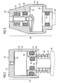
- FIG 1 shows an injection valve 10 for direct-injection gasoline engines.
- the injection valve 10 has a double tube design in which the housing 12 comprises an outer tubular member 121 and an inner tubular member 123, forming an annular fluid supply passage 14 between them.
- Gasoline under pressure is provided to an inlet fitting 16, from where it is flows through the annular supply passage 14 and enters into an axial outlet passage 20, projecting through the lower part of the housing 12.
- the outlet passage 20 terminates in a metering opening 22 surrounded by a valve seat which is opened or closed by the axial movement of a valve needle passing through the outlet passage 20.
- a piezoelectric actuator 28 Upon activation of a piezoelectric actuator 28, gasoline is injected into the engine cylinder. When an excitation voltage is applied to the piezoelectric actuator 28, its length in axial direction increases by a predetermined amount. The extension in length is transmitted to the valve needle which lifts from the valve seat and begins the injection of pressurized gasoline. When the excitation voltage is terminated, the length of the piezoelectric actuator 28 decreases to its normal value and the valve needle 24 is pushed back in its closing position.
- the outer steel housing 12 has a higher thermal coefficient of expansion than the material of the piezoelectric actuator 28, changes in the operation temperature need to be compensated by a thermal compensator unit 30 to ensure safe operation of the injector.
- FIG. 2 shows a schematic axial cross section of the thermal compensator unit 30 of Fig. 1 in detail.
- the compensator housing 32 contains a hydraulic piston 34 which is able to slide axially inside it.
- the housing 32 rests via its upper surface 54 on the fixed end stop of the injector 10, while the lower end rod 48 of the piston 34 is in contact with the piezoelectric actuator 28.
- the piston 34 and the compensator housing form a first fluid chamber 36, a second fluid chamber 38 and a small annular throttling gap 40 connecting the two fluid chambers.
- the fluid chambers 36, 38 are filled with a hydraulic fluid, for example with silicone oil.
- the piston 34 is pushed upward by the expansion of the piezoelectric actuator 28 and this forces the silicone oil contained inside the chamber 36 through the peripheral throttling gap 40 of the piston 34 sliding in the housing 32, thereby filling the lower oil chamber 38.
- the ring element 42 moves downward, the lower oil chamber 38 expands during the activation phase.
- Two rubber seals 44 and 46 seal the silicone oil containing chambers against the surrounding.
- the volume of oil contained in the second chamber 38 can move back toward the first chamber 36 either via the annular throttling gap 40 or via a channel formed in the head of the piston 34 that connects the chambers 36 and 38 to each other.
- a metal strip may then be spot-welded to the upper face of the piston 34, offering hydraulic leak tightness during the activation phase of the actuator and a pathway for the silicone oil during the subsequent deactivation phase, owing to the way the metal strip bends.
- FIG. 3 shows a schematic axial cross section of a thermal compensator unit 60 according to another embodiment of the invention.
- same reference numbers relate to same or corresponding parts.
- the compensator housing 32 contains a piston 34 mounted axially slideable inside it.
- the housing 32 rests via its upper surface 54 on the fixed end stop of the injector, while the lower end of the piston 34 is in contact with the piezoelectric actuator 28.
- First 36 and second 38 fluid chambers and a small annular throttling gap 40 are formed between the piston 34 and the compensator housing 32, the two chambers 36 and 38 having the same radial cross section.
- the piston 34 is pushed upward by the expansion of the piezoelectric actuator 28 and this forces the silicone oil contained inside the chambers 36 by the two seals 46 and 44 through the peripheral throttling gap 40, filling the lower oil chamber 38.
- the volume of oil contained in the second chamber 38 can move back toward the first chamber 36 either via the annular throttling gap 40 or via a channel formed in the head of the piston 34 that connects the chambers 36 and 38 to each other.
- a metal strip offering hydraulic leak tightness during the activation phase of the actuator and a pathway for the silicone oil during the subsequent deactivation phase may be spot-welded to the upper face of the piston 34.
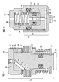
- FIG. 4 A further embodiment of the invention is shown in the schematic cross section of Fig. 4.
- the compensator housing 32 of the thermal compensator unit 70 contains a piston 34, whose upper part is disposed axially slideable inside the housing 32.
- the lower part of the piston 34 slides inside a moveable ring member 82 against which it is sealed.
- the housing 32 rests via its upper surface 54 on the fixed end stop of the injector, while the lower end of the piston 34 is in contact with the piezoelectric actuator 28.
- the first fluid chamber 36 is formed between the top surface of the piston 34 and the compensator housing 32.
- a bellows 72 is connected to the compensator housing 32 and to the moveable ring member 82.
- the second fluid chamber 38 is formed between the piston 34 and the bellows 72 and a small annular gap between the piston 34 and the housing 32 forms the throttling gap 40.
- the piston 34 is pushed upward by the expansion of the piezoelectric actuator 28 and this forces the silicone oil contained inside the chamber 36 through the peripheral throttling gap 40, filling the lower oil chamber 38, which will expand as the ring member 82 moves downward.
- the continual movements of oil between the chambers 36 and 38 require the presence of the bellows 72 welded to the compensator housing 32 and to the moveable ring member 82.
- the volume of oil contained in the second chamber 38 can move back toward the first chamber 36 either via the annular throttling gap 40 or via a channel 74 formed in the head of the piston 34.
- the opening 76 facing the first fluid chamber 36 is covered with a metal strip 80, while the opening 78 facing the second fluid chamber 38 remains uncovered.
- the strip 80 prevents leakage of oil during activation of the actuator 28 and is able to bend under the pressure of the returning oil to open a gap for the oil to move back from the second fluid chamber 38 to the first fluid chamber 36 during the deactivation phase of the actuator 28.
- FIG. 5 A further design of a thermal compensator unit 90 according to the invention is shown in Fig. 5.
- the housing 32 contains a piston 34 able to slide axially inside it.
- a closing element 96 rests via its upper surface on the fixed end stop of the injector 10 while the lower end of the housing 32 is in contact with the piezoelectric actuator 28.
- a moveable ring member 92 is provided in a borehole 100 of the piston 34, the ring member 92 being connected to a helical spring 94 acting on the ring member 92 and the closing element 96.
- the first fluid chamber 36 is formed between the lower surface of the piston 34 and the compensator housing 32
- the second fluid chamber 38 is formed between the inside surface of the borehole 100 and the ring member 92.
- a throttling passage between the first and second fluid chamber 36 and 38 is formed by a straight passage 102, extending through the lower portion of the piston 34.
- the straight passage 102 is covered by a perforated strip 98 having a small hole to provide high hydraulic resistance to the flow of oil during the expansion of the actuator 28.
- the piston 34 is pushed downward by the expansion of the piezoelectric actuator 28 during the activation phase of the piezoelectric actuator 28. This movement forces the silicone oil contained inside the chambers 36 through the hole formed in the strip 98, slowly filling the second fluid chamber 38.
- the volume of oil contained in the second chamber 38 can move back toward the first chamber 36 due to the bending of the strip 98, which is welded to the piston at two points of its outer circumference only.
- the strip 98 provides good hydraulic resistance to the flow of oil during the expansion of the actuator and is able to bend, opening a gap for the oil to move back from the first fluid chamber 38 to the second fluid chamber 36 during the deactivation phase of the actuator 28.
Landscapes
- Engineering & Computer Science (AREA)
- Chemical & Material Sciences (AREA)
- Combustion & Propulsion (AREA)
- Mechanical Engineering (AREA)
- General Engineering & Computer Science (AREA)
- Fuel-Injection Apparatus (AREA)
Abstract
a housing (12) having a metering opening (22), controllable by the movement of an axially moveable valve needle, an axially extendable piezoelectric actuator (28) cooperating with the valve needle to control its axial movement, and a thermal compensator unit (30) to compensate for different thermal expansion of the housing (12) and the piezoelectric actuator (28). According to the invention the thermal compensator unit (30) comprises a compensator housing (32) and a hydraulic piston (34), disposed axially slidable within the compensator housing (32), the compensator housing (32) and the piston (34) forming a first fluid chamber (36), a second fluid chamber (38) and a throttling passage (40) connecting the first (36) and second fluid chamber (38), and means for transmitting an axial extension of the piezoelectric actuator (28) to the compensator housing (32) or to the piston (34) to urge a hydraulic fluid from the first fluid chamber (36) to the second fluid chamber (38) in an activation phase of the piezoelectric actuator (28).
Description
- Figure 1
- is a schematic axial cross section of an injector valve with a thermal compensator unit according to an embodiment of the invention;
- Figure 2
- is a schematic axial cross section of the thermal compensator unit of Fig. 1 in detail;
- Figure 3
- is a schematic axial cross section of a thermal compensator unit according to another embodiment of the invention;
- Figure 4
- is a schematic axial cross section of a thermal compensator unit according to a further embodiment of the invention;
- Figure 5
- is a schematic axial cross section of a thermal compensator unit according to still a further embodiment of the invention.
Claims (15)
- A metering device for dosing pressurized fluids, particularly an injection valve for a fuel injection system in an internal combustion engine, comprisingcharacterized in thata housing (12) having a metering opening (22), controllable by the movement of an axially moveable valve needle, the housing (12) comprising a material having a first thermal coefficient of expansion,an axially extendable piezoelectric actuator (28) cooperating with the valve needle to control its axial movement, the piezoelectric actuator (28) comprising a material having a second thermal coefficient of expansion, anda thermal compensator unit (30; 60; 70; 90) cooperating with the piezoelectric actuator (28) and the housing (12) to compensate for different thermal expansion of the housing (12) and the piezoelectric actuator (28) to ensure elastic contact between an end stop of the housing (12), the piezoelectric actuator (28) and the valve needle,
the thermal compensator unit (30; 60; 70; 90) comprisesa compensator housing (32) and a hydraulic piston (34), disposed axially slidable within the compensator housing (32), the compensator housing (32) and the piston (34) forming a first fluid chamber (36), a second fluid chamber (38) and a throttling passage (40; 102) connecting the first (36) and second fluid chamber (38), andmeans for transmitting an axial extension of the piezoelectric actuator (28) to the compensator housing (32) or to the piston (34) to urge a hydraulic fluid from the first fluid chamber (36) to the second fluid chamber (38) in an activation phase of the piezoelectric actuator (28). - The metering device according to claim 1,
characterized in that
the thermal compensator unit (30; 60; 70; 90) further comprises restoring means (50; 62; 94) to return the hydraulic piston (34) to its initial position and to return the hydraulic fluid from the second fluid chamber (38) to the first fluid chamber (36) in a deactivation phase of the piezoelectric actuator (28). - The metering device according to any of the preceding claims, characterized in that
a return passage (74; 102) for the hydraulic fluid between the second (38) and first fluid chamber (36) is provided inside the hydraulic piston (34) for rapidly returning the hydraulic fluid in a deactivation phase of the piezoelectric actuator (28). - The metering device according to claim 3, characterized in that
the return passage (74; 102) through the piston (34) has an opening (76) in the first fluid chamber (36), the opening (76) being covered by a spot-welded metal strip (80; 98) which is pressed on the opening (76) in the activation phase and which bends away form the opening (76) in the deactivation phase due to the pressure exerted by the hydraulic fluid, to rapidly return the hydraulic fluid to the first fluid chamber (36). - The metering device according to any of the preceding claims, characterized in that
an upper surface of the compensator housing (32) is connected to the end stop of the housing (12), and that a lower surface of the hydraulic piston (34) is connected to the piezoelectric actuator (28). - The metering device according to any of claims 1 to 4, characterized in that
an upper surface of the compensator housing (32) is connected to the bottom end of the piezoelectric actuator (28) and a lower surface of the hydraulic piston (34) is connected to the top of the valve needle. - The metering device according to claim 5 or 6, characterized in that
the restoring means comprises a helical spring (50) acting on the hydraulic piston (34) via an end stop plate (52) connected to an end portion of the hydraulic piston (34), the helical spring (50) being precompressed during the assembly process, the hydraulic fluid being pressurized and the piston (34) applying a pre-load contact force to the piezoelectric actuator (28) and the valve needle, at any operating condition, the helical spring (50) further being compressed by an axial extension of the piezoelectric actuator (28). - The metering device according to claim 5 or 6, characterized in that
the restoring means comprises a Belleville washer (62) arranged between the hydraulic piston (34) and the upper surface of the compensator housing (32), the Belleville washer (62) being compressed by an axial extension of the piezoelectric actuator (28). - The metering device according to claim 5 or 6, characterized in that
the hydraulic piston (34) has an upper part sliding within the compensator housing (32) and a lower part sliding within a surrounding moveable ring member (82), and that a bellows (72) is connected to the compensator housing (32) and the moveable ring member (82), wherein the first fluid chamber (36) is formed between the piston (34) and the compensator housing (32) and the second fluid chamber (38) is formed between the piston (34) and the bellows (72). - The metering device according to any of claims 5 to 9, characterized in that
the throttling passage (40) is formed by a small gap between the piston and (34) the compensator housing (32). - The metering device according to any of claims 1 to 4, characterized in that
a lower surface of the compensator housing (32) is connected to the piezoelectric actuator (28) and that a closing element (96) is connected to the end stop of the housing (12). - The metering device according to any of claims 1 to 4, characterized in that
an upper surface of the compensator housing (32) is connected to the bottom end of the piezoelectric actuator (28) and a lower surface of the hydraulic piston (34) is connected to the top of the valve needle. - The metering device according to claim 11 or 12, characterized in that
a moveable ring member (92) is provided in a borehole (100) of the piston, the ring member (92) being connected to a helical spring (94) acting on the ring member (92) and the closing element (96), the helical spring (94) being compressed by an axial extension of the piezoelectric actuator (28). - The metering device according to any of claims 11 to 14, characterized in that
the first fluid chamber (36) is formed between the piston (34) and the compensator housing (32), and the second fluid chamber (38) is formed between an inside surface of the borehole (100) and the ring member (92). - The metering device according to any of claims 11 to 14, characterized in that
the throttling passage is formed by a straight passage (102) through the lower portion of the piston (34), the passage (102) being covered by a perforated strip (98), the strip (98) providing good hydraulic resistance to the flow of hydraulic fluid during the expansion of the actuator and being able to bend, opening a gap for the hydraulic fluid to move back from the first fluid chamber (38) to the second fluid chamber (36) during the deactivation phase of the actuator (28).
Priority Applications (2)
| Application Number | Priority Date | Filing Date | Title |
|---|---|---|---|
| DE2002604565 DE60204565T2 (en) | 2002-08-20 | 2002-08-20 | Dosing device with thermal compensation unit |
| EP20020018666 EP1391608B1 (en) | 2002-08-20 | 2002-08-20 | Metering device with thermal compensator unit |
Applications Claiming Priority (1)
| Application Number | Priority Date | Filing Date | Title |
|---|---|---|---|
| EP20020018666 EP1391608B1 (en) | 2002-08-20 | 2002-08-20 | Metering device with thermal compensator unit |
Publications (2)
| Publication Number | Publication Date |
|---|---|
| EP1391608A1 true EP1391608A1 (en) | 2004-02-25 |
| EP1391608B1 EP1391608B1 (en) | 2005-06-08 |
Family
ID=30775825
Family Applications (1)
| Application Number | Title | Priority Date | Filing Date |
|---|---|---|---|
| EP20020018666 Expired - Fee Related EP1391608B1 (en) | 2002-08-20 | 2002-08-20 | Metering device with thermal compensator unit |
Country Status (2)
| Country | Link |
|---|---|
| EP (1) | EP1391608B1 (en) |
| DE (1) | DE60204565T2 (en) |
Cited By (4)
| Publication number | Priority date | Publication date | Assignee | Title |
|---|---|---|---|---|
| EP1524427A1 (en) * | 2003-10-09 | 2005-04-20 | Siemens Aktiengesellschaft | Piezoelectric actuator with compensator |
| EP1731753A1 (en) * | 2005-06-06 | 2006-12-13 | Siemens Aktiengesellschaft | Injection valve and compensator for an injection valve |
| EP1887216A1 (en) * | 2006-08-02 | 2008-02-13 | Siemens Aktiengesellschaft | Thermal compensation arrangement in an injection valve |
| EP1972779A1 (en) * | 2007-03-19 | 2008-09-24 | Robert Bosch Gmbh | Hydraulic coupler |
Citations (3)
| Publication number | Priority date | Publication date | Assignee | Title |
|---|---|---|---|---|
| EP1046809A2 (en) * | 1999-04-20 | 2000-10-25 | Siemens Aktiengesellschaft | Fluid metering device |
| US20010035164A1 (en) * | 1999-10-15 | 2001-11-01 | Irawan Rahardja | Directly actuated injection valve with a composite needle |
| WO2002031344A1 (en) * | 2000-10-11 | 2002-04-18 | Siemens Vdo Automotive Corporation | Dual-spring compensator assembly for a fuel injector and method |
-
2002
- 2002-08-20 EP EP20020018666 patent/EP1391608B1/en not_active Expired - Fee Related
- 2002-08-20 DE DE2002604565 patent/DE60204565T2/en not_active Expired - Fee Related
Patent Citations (4)
| Publication number | Priority date | Publication date | Assignee | Title |
|---|---|---|---|---|
| EP1046809A2 (en) * | 1999-04-20 | 2000-10-25 | Siemens Aktiengesellschaft | Fluid metering device |
| US20010035164A1 (en) * | 1999-10-15 | 2001-11-01 | Irawan Rahardja | Directly actuated injection valve with a composite needle |
| WO2002031344A1 (en) * | 2000-10-11 | 2002-04-18 | Siemens Vdo Automotive Corporation | Dual-spring compensator assembly for a fuel injector and method |
| US20020047100A1 (en) * | 2000-10-11 | 2002-04-25 | Jack Lorraine | Pressure responsive valve for a compensator in a solid state actuator |
Cited By (5)
| Publication number | Priority date | Publication date | Assignee | Title |
|---|---|---|---|---|
| EP1524427A1 (en) * | 2003-10-09 | 2005-04-20 | Siemens Aktiengesellschaft | Piezoelectric actuator with compensator |
| EP1731753A1 (en) * | 2005-06-06 | 2006-12-13 | Siemens Aktiengesellschaft | Injection valve and compensator for an injection valve |
| US7673811B2 (en) | 2005-06-06 | 2010-03-09 | Siemens Aktiengesellschaft | Injection valve and compensating element for an injection valve |
| EP1887216A1 (en) * | 2006-08-02 | 2008-02-13 | Siemens Aktiengesellschaft | Thermal compensation arrangement in an injection valve |
| EP1972779A1 (en) * | 2007-03-19 | 2008-09-24 | Robert Bosch Gmbh | Hydraulic coupler |
Also Published As
| Publication number | Publication date |
|---|---|
| DE60204565T2 (en) | 2005-11-03 |
| EP1391608B1 (en) | 2005-06-08 |
| DE60204565D1 (en) | 2005-07-14 |
Similar Documents
| Publication | Publication Date | Title |
|---|---|---|
| US7886993B2 (en) | Injection valve | |
| US6499471B2 (en) | Hydraulic compensator for a piezoelectrical fuel injector | |
| KR20000015898A (en) | Fuel injection valve with a piezo-electric or magnetostrictive actuator | |
| US6564777B2 (en) | Directly actuated injection valve with a composite needle | |
| WO2002095214A1 (en) | Directly actuated injection valve with a ferromagnetic needle | |
| US6948667B2 (en) | Fuel injector | |
| US6749126B1 (en) | Fuel injector and method for its operation | |
| KR100853645B1 (en) | Fuel injection valve | |
| US6932278B2 (en) | Fuel injection valve | |
| KR20130016298A (en) | Valve assembly for an injection valve, injection valve and method for assembling a valve assembly of an injection valve | |
| EP1391608B1 (en) | Metering device with thermal compensator unit | |
| US6681999B1 (en) | Fuel injection valve | |
| US6899284B1 (en) | Fuel-injection valve | |
| EP3482063B1 (en) | Valve assembly for an injection valve, injection valve and injection method | |
| US6840459B1 (en) | Fuel injection valve | |
| US20060043213A1 (en) | Fuel injection valve | |
| KR20040111432A (en) | Feul injection valve | |
| EP1813805A1 (en) | Compensation assembly for an injector | |
| US7422006B2 (en) | Fuel injector | |
| EP1464828B1 (en) | Thermal compensator unit for use in a metering device | |
| EP1391609B1 (en) | Metering device with hydraulic bushing element | |
| JP2005520967A (en) | Fuel injection valve | |
| JP2008008281A (en) | Fuel injection valve | |
| JP5592741B2 (en) | Fuel injection valve | |
| EP2067981B1 (en) | Valve assembly for an injection valve and injection valve |
Legal Events
| Date | Code | Title | Description |
|---|---|---|---|
| PUAI | Public reference made under article 153(3) epc to a published international application that has entered the european phase |
Free format text: ORIGINAL CODE: 0009012 |
|
| 17P | Request for examination filed |
Effective date: 20030804 |
|
| AK | Designated contracting states |
Kind code of ref document: A1 Designated state(s): AT BE BG CH CY CZ DE DK EE ES FI FR GB GR IE IT LI LU MC NL PT SE SK TR |
|
| AX | Request for extension of the european patent |
Extension state: AL LT LV MK RO SI |
|
| GRAP | Despatch of communication of intention to grant a patent |
Free format text: ORIGINAL CODE: EPIDOSNIGR1 |
|
| AKX | Designation fees paid |
Designated state(s): DE FR IT |
|
| GRAS | Grant fee paid |
Free format text: ORIGINAL CODE: EPIDOSNIGR3 |
|
| GRAA | (expected) grant |
Free format text: ORIGINAL CODE: 0009210 |
|
| AK | Designated contracting states |
Kind code of ref document: B1 Designated state(s): DE FR IT |
|
| REF | Corresponds to: |
Ref document number: 60204565 Country of ref document: DE Date of ref document: 20050714 Kind code of ref document: P |
|
| ET | Fr: translation filed | ||
| PLBE | No opposition filed within time limit |
Free format text: ORIGINAL CODE: 0009261 |
|
| STAA | Information on the status of an ep patent application or granted ep patent |
Free format text: STATUS: NO OPPOSITION FILED WITHIN TIME LIMIT |
|
| 26N | No opposition filed |
Effective date: 20060309 |
|
| PGFP | Annual fee paid to national office [announced via postgrant information from national office to epo] |
Ref country code: DE Payment date: 20080822 Year of fee payment: 7 |
|
| PGFP | Annual fee paid to national office [announced via postgrant information from national office to epo] |
Ref country code: FR Payment date: 20080813 Year of fee payment: 7 Ref country code: IT Payment date: 20080822 Year of fee payment: 7 |
|
| REG | Reference to a national code |
Ref country code: FR Ref legal event code: ST Effective date: 20100430 |
|
| PG25 | Lapsed in a contracting state [announced via postgrant information from national office to epo] |
Ref country code: DE Free format text: LAPSE BECAUSE OF NON-PAYMENT OF DUE FEES Effective date: 20100302 Ref country code: FR Free format text: LAPSE BECAUSE OF NON-PAYMENT OF DUE FEES Effective date: 20090831 |
|
| PG25 | Lapsed in a contracting state [announced via postgrant information from national office to epo] |
Ref country code: IT Free format text: LAPSE BECAUSE OF NON-PAYMENT OF DUE FEES Effective date: 20090820 |