EP1389750A1 - Securité d'un disc dur - Google Patents
Securité d'un disc dur Download PDFInfo
- Publication number
- EP1389750A1 EP1389750A1 EP02292028A EP02292028A EP1389750A1 EP 1389750 A1 EP1389750 A1 EP 1389750A1 EP 02292028 A EP02292028 A EP 02292028A EP 02292028 A EP02292028 A EP 02292028A EP 1389750 A1 EP1389750 A1 EP 1389750A1
- Authority
- EP
- European Patent Office
- Prior art keywords
- message
- identification
- box
- time value
- identity
- Prior art date
- Legal status (The legal status is an assumption and is not a legal conclusion. Google has not performed a legal analysis and makes no representation as to the accuracy of the status listed.)
- Withdrawn
Links
Images


Classifications
-
- H—ELECTRICITY
- H04—ELECTRIC COMMUNICATION TECHNIQUE
- H04N—PICTORIAL COMMUNICATION, e.g. TELEVISION
- H04N21/00—Selective content distribution, e.g. interactive television or video on demand [VOD]
- H04N21/40—Client devices specifically adapted for the reception of or interaction with content, e.g. set-top-box [STB]; Operations thereof
- H04N21/41—Structure of client; Structure of client peripherals
- H04N21/426—Internal components of the client ; Characteristics thereof
- H04N21/42661—Internal components of the client ; Characteristics thereof for reading from or writing on a magnetic storage medium, e.g. hard disk drive
-
- G—PHYSICS
- G06—COMPUTING; CALCULATING OR COUNTING
- G06F—ELECTRIC DIGITAL DATA PROCESSING
- G06F21/00—Security arrangements for protecting computers, components thereof, programs or data against unauthorised activity
- G06F21/30—Authentication, i.e. establishing the identity or authorisation of security principals
- G06F21/44—Program or device authentication
- G06F21/445—Program or device authentication by mutual authentication, e.g. between devices or programs
-
- G—PHYSICS
- G06—COMPUTING; CALCULATING OR COUNTING
- G06F—ELECTRIC DIGITAL DATA PROCESSING
- G06F21/00—Security arrangements for protecting computers, components thereof, programs or data against unauthorised activity
- G06F21/70—Protecting specific internal or peripheral components, in which the protection of a component leads to protection of the entire computer
- G06F21/78—Protecting specific internal or peripheral components, in which the protection of a component leads to protection of the entire computer to assure secure storage of data
- G06F21/80—Protecting specific internal or peripheral components, in which the protection of a component leads to protection of the entire computer to assure secure storage of data in storage media based on magnetic or optical technology, e.g. disks with sectors
-
- H—ELECTRICITY
- H04—ELECTRIC COMMUNICATION TECHNIQUE
- H04N—PICTORIAL COMMUNICATION, e.g. TELEVISION
- H04N21/00—Selective content distribution, e.g. interactive television or video on demand [VOD]
- H04N21/40—Client devices specifically adapted for the reception of or interaction with content, e.g. set-top-box [STB]; Operations thereof
- H04N21/43—Processing of content or additional data, e.g. demultiplexing additional data from a digital video stream; Elementary client operations, e.g. monitoring of home network or synchronising decoder's clock; Client middleware
- H04N21/436—Interfacing a local distribution network, e.g. communicating with another STB or one or more peripheral devices inside the home
- H04N21/4367—Establishing a secure communication between the client and a peripheral device or smart card
-
- H—ELECTRICITY
- H04—ELECTRIC COMMUNICATION TECHNIQUE
- H04N—PICTORIAL COMMUNICATION, e.g. TELEVISION
- H04N5/00—Details of television systems
- H04N5/76—Television signal recording
- H04N5/91—Television signal processing therefor
- H04N5/913—Television signal processing therefor for scrambling ; for copy protection
- H04N2005/91357—Television signal processing therefor for scrambling ; for copy protection by modifying the video signal
- H04N2005/91364—Television signal processing therefor for scrambling ; for copy protection by modifying the video signal the video signal being scrambled
Definitions
- the invention relates to a digital data processing system in which a first device of the system cooperates with a second device of the system.
- a mass storage device is a device that allows for storage of relatively large amounts of data for subsequent processing or retrieval.
- a mass storage device is generally connected to a data processing system such as for example a personal computer, an audio/visual player or recorder, a digital camera, a mobile digital device, or a digital television Set Top Box (STB).
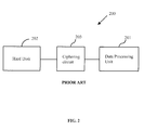
- Fig. 1 shows a typical system 100 comprising a data processing system 101 and a mass storage device 102 connected to the data processing system 101.
- the data processing system 101 may also include a microprocessor, Random Access Memory (RAM) and Read Only Memory (ROM) memory, an operating system (not shown), etc....
- RAM Random Access Memory
- ROM Read Only Memory
- the system 100 may further include additional peripheral devices such as an audio/visual device 103 for rendering graphics and sound produced by the system 100, and an input device 104 that allows a user to enter commands and data into the system 100.
- the mass storage device 102 may store information produced by the data processing system 101 or received from outside of the system 100, and allow stored information to be available for retrieval and processing.
- mass storage devices include optical storage devices (that generally use an optical disk as data storage support), magnetic and opto-magnetic storage devices (that generally are based on tape or disk data supports).
- optical storage devices that generally use an optical disk as data storage support
- magnetic and opto-magnetic storage devices that generally are based on tape or disk data supports.
- One widespread type of mass storage device is a magnetic Hard Disk (HD) device that has many advantageous characteristics such as rapid random access to data stored, reduced size and affordable price.
- HD Hard Disk
- the mass storage device may be used to store confidential data or data that should not be used outside of the data processing system.
- a HD in a STB may be used to record movies.
- FIG. 2 shows an example of a computer system 200 comprising a data processing unit 201 and a hard disk 202 that are interfaced with a ciphering circuit 203.
- the data enciphering / deciphering circuit 203 is enabled.
- the data enciphering / deciphering circuit 203 is implemented in hardware in order to minimise the use of the computer's CPU.
- the computer system 200 allows storage of secured data on the mass storage device 202 in that it requires the data enciphering /deciphering circuit 203 to use decipher the stored data.
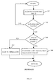
- US 6,243,813 discloses a computer system having a detachable security device.
- the security device determines whether a hard disk in the computer may boot.
- the computer system determines whether the hard disk is the hard disk that was initially installed in the computer system. Further, the computer system also determines whether the security device is the security device that was initially installed in the computer system.
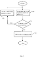
- These checks are performed by comparing an identification of the computer system, the hard disk and the security device with each other as shown in box 300 in a flowchart in Fig. 3. The checking can only be performed after receiving a password from the user in box 301, and verifying in box 302 that the password matches a password stored in the computer or on the hard disk. If ID numbers are found to be different the computer operation is stopped in box 303. If the ID numbers are found to be the same, then copy protection measures for data stored on the hard disk are implemented in box 304. In addition, data stored on the hard disk is encrypted.
- the invention provides a method for securing a system comprising a first device cooperating with a second device, the first device and the second device respectively comprising a first encryption feature and a second encryption feature.
- the method comprises performing a mutual verification of identity between the first device and the second device.
- the method further comprises interrupting the cooperation between the first device and the second device if the mutual verification of identity between the first device and the second device fails.
- the invention provides a method for securing a system, in which the performing of the mutual verification further comprises
- the performing of the mutual verification further comprises
- the performing of the mutual verification comprises
- the invention provides a method for securing a system comprising a first device cooperating with a second device, the method comprising
- the method for securing a system comprises
- the method for securing a system comprises
- the monitoring of an occurrence of a mutual verification of identity comprises
- the invention provides a method for securing a system comprising a first device and a second device, the method comprising
- the invention provides a system comprising a first device and a second device connected to exchange data.
- the system further comprises
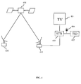
- Fig. 4 contains a schematic overview of a digital television broadcast and reception system.
- a provider broadcasts a bundle of services by means of satellite emitter 400 towards a telecommunication satellite 401, from which the bundle of services is emitted towards a satellite dish receiver 402.
- a digital Set Top box (STB) 403 receives the bundle of services and decodes a service contained therein. The decoded service is then processed in the STB 403.
- the STB 403 has an output towards an audio/video rendering device, e.g. a television 404.
- the STB 403 comprises hardware and software components (not shown in Fig. 4) which allow, for example, the STB 403 to execute software stored in the STB 403 or received in the bundle of service by way of broadcast.
- the STB 403 may enable access to various services such as television programs, music programs but also interactive applications, electronic program guides, online commerce, video on demand, etc...
- Fig. 4 The overview in Fig. 4 is given as an example only. Many other configurations such as a terrestrial or cable broadcast network could be used instead to bring services to the STB 403.
- a Hard Disk (HD) 405 is connected to the STB 403.
- the HD 405 is shown distinct from the STB 403 for reasons of clarity.
- the HD 405 may of course be included inside a box of the STB 403 and become an integral part of the STB 403.
- the HD 405 is used as a mass storage device and may store software, data corresponding to television or music programs or other data as allowed by the STB 403.
- Recent STB applications include access to the internet, video on demand, recording of programs, time shifting while watching a live broadcast program. These applications tend to make an extensive use of the HD 405.
- inventive examples described hereafter allow to uniquely associate the HD 405 and the STB 403 by way of pairing, and to verify during operation and cooperation of the HD 405 and the STB 403 that only the initially associated HD 405 and STB 403 are used.
- Fig. 5 contains an example of a system in which a STB 500 cooperates with a HD 501 through a connection 502.
- the connection 502 may for example be a data bus in which commands are exchanged according to a determined protocol.
- a protocol is typically an ATA/ATAPI standard well known in the art.
- the protocol and the commands defined therein may be adapted to exchange specific messages and data, as required by the invention.
- Other suitable protocols may well be used instead of the ATA/ATAPI standard.
- the STB 500 comprises STB encryption features 503 that may be used to secure data exchanges between the STB 500 and the HD 501.
- the STB 500 further comprises STB memory 504, e.g. RAM, ROM, Electrically Erasable Programmable Read-Only Memory (EEPROM)), Flash memory or any other type of memory, and a processing unit 505.
- the processing unit 505 includes functionality to process data stored in STB memory 504, to generate random data, to generate and measure time delays, etc... More generally the processing unit 505 may be designed to control an operation of the STB 500 and devices connected to the STB 500.
- the HD 501 comprises HD encryption features 506 that may be used to secure data exchanges between the HD 501 and the STB 500.
- the HD 501 further comprises HD memory 507, e.g. RAM, ROM, EEPROM, Flash memory or any other type of memory, and a processing unit 508.
- the processing unit 505 includes functionality toprocess data stored in the HD memory 507, to generate random data, and to generate and measure time delays. More generally the processing unit 508 may be designed to control an operation of the HD 501 and devices connected to the HD 501.
- a manufacturing of a system comprising a HD and a STB includes a customisation step, or pairing, which allows the system to uniquely associate the HD and the STB.
- the pairing may be based on individual serial numbers of the HD and STB used in the system.
- Each HD and STB respectively, has a unique identification number that is stored as a serial number in a memory of the HD and STB at manufacturing of the HD and the STB.
- the pairing may be further based on key pairs, each comprising a private and a public key.
- Such keys are typically used to hash and sign messages and data.
- the private and the public keys of a pair are used at different location. As suggested by the name, the private key is kept secret by its owner while the corresponding public key may be freely distributed.
- the private key in particular is used to sign and hash a message.
- the hashed and signed message may only be correctly recovered with the use of the corresponding public key. Accordingly, a recipient of the hashed and signed message needs to be in possession of the corresponding public key.
- the corresponding public key may be used by anyone to encrypt a message. The resulting encrypted message may only be decrypted using the private key.
- each separate HD-STB system has its own and unique 2 pairs of keys.
- Both the HD and the STB include specific pairing software that allows them to exchange pairing data and to store the pairing data at determined locations as will be explained hereunder.
- the pairing software may for example be a specific set of commands to control an operation of the HD.
- a corresponding standard set of commands may be adapted for the pairing. For example if the well known ATA/ATAPI 5 commands are used, it may be necessary to suppress certain standard commands, such as a command for downloading a firmware of the HD, and to add new commands to enable new functions.
- the pairing software may comprise specific software for the STB, such as a pairing library.
- the pairing software may be designed to be partly used after the pairing as well in a subsequent process of mutual verification of identity as will be described in a dedicated section of this specification. In this case a part of the software used for pairing only is deleted from the HD and/or the STB after the pairing.
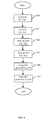
- a flow chart shows an example of steps executed by the pairing software that is executed for example in the STB. All data sent from the STB to the HD is sent using an ATA command.
- a pair of private and public keys Pr2 and Pu2 is generated for the HD in box 601. Similarly a pair of private and public keys Pr1 and Pr1 is generated for the STB in box 600.
- the pairing software stores the private key Pr1 and the public key Pu2 in the STB as shown in box 602.
- the private key Pr2 and the public key Pu2 may be stored in an EEPROM memory of the STB.
- the pairing software stores the private key Pr2 and the public key Pu1 in the HD as shown in box 603. This can for example be in an EEPROM memory of the HD.
- an address in the STB EEPROM at which the keys Pr1 and Pu2 have been stored may be stored as well and later be used during a mutual verification of identity between the STB and the HD to find and retrieve the keys Pr1 and Pu2.
- an address in the HD EEPROM at which keys Pr2 and Pu1 have been stored may be stored as well and later be used during a mutual verification of identity between the STB and the HD to find and retrieve the keys Pr2 and Pu1.
- Further steps executed by the pairing software include reading an identification ID1 from the STB, e.g., a serial number permanently stored in the STB, and storing ID1 in the HD as shown in box 604. This can for example be in an EEPROM memory of the HD.
- the pairing software then executes a reading of an identification ID2 from the HD, e.g., a serial number permanently stored in the HD, and storing ID2 in the STB as shown in box 605.
- an identification ID2 e.g., a serial number permanently stored in the HD
- ID2 e.g., a serial number permanently stored in the HD
- This can for example be in an EEPROM memory of the STB.
- the pairing software performs all the storing and exchange operations described in reference to Fig. 6 automatically without intervention from the manufacturer. This way the content of the messages exchanged between the HD and the STB remains hidden from the manufacturer.
- the mutual verification of identity typically occurs while the STB and HD cooperate in an operation of the STB system.
- the STB and HD perform a process which allows them to verify that the STB-HD system has not been changed since the pairing process, i.e., that the STB and the HD used are unchanged since pairing.
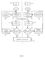
- Fig. 7 contains a flowchart illustrating a general example of a mutual verification of identify between the STB and the HD.
- the mutual verification of identity is performed in box 700. If the verification is successful in box 701, i.e. if the verification shows that the STB and the HD mutually recognize each other, then further cooperation between the STB and the HD is enabled in box 702 and the mutual verification of identity may be performed again at a later time. If no successful verification is achieved, the cooperation between the STB and the HD is interrupted, as shown in box 703.
- the system of STB and HD implements appropriate measures to interrupt cooperation, e.g., the system stops, the HD erases itself, or the system displays generates an error signal. Any other measures to interrupt cooperation may be used.
- Fig. 8 contains a flowchart illustrating an example of steps performed in a STB and steps performed in a HD.
- determined data 1 is produced in box 802 by using an encryption feature 1 shown in box 803.
- the encryption feature 803 may be a feature specific to the STB 800, e.g., a determined key, a determined encryption algorithm or any other characteristic of encryption.
- the determined data 1 is then transmitted to the HD 801 and verified in box 804.
- the verification in box 804 checks whether determined data 1 is characteristic of the encryption feature 1.
- the verification in box 804 may therefore require to use information related to the encryption feature 1 or to the determined data 1 (not shown in Fig. 8) that was previously stored in the HD 801. If the verification in box 804 is recognised as successful in box 805, then further cooperation between the STB and the HD is enabled in box 806. In the case where the verification fails to be successful, the cooperation is interrupted in box 807.
- determined data 2 is produced in box 808 by using an encryption feature 2 shown in box 809.
- the encryption feature 809 may be a feature specific to the HD 801, e.g., a determined key, a determined encryption algorithm or any other characteristic of encryption.
- the determined data is then transmitted to the STB 800 and verified in box 810.
- the verification in box 810 checks whether determined data 2 is characteristic of the encryption feature 2.
- the verification in box 810 may therefore require to use information related to the encryption feature 2 or to the determined data 2 (not shown in Fig. 8) that was previously stored in the STB 800. If the verification in box 810 is recognised as successful in box 811, then further cooperation between the STB and the HD is enabled in box 812. In the case where the verification fails to be successful, the cooperation is interrupted in box 807.
- any verification leading to an interruption of cooperation in box 807 prevails on a successful verification, i.e., it is sufficient that only one verification 804 or 810 fails to be successful to result in an interrupted cooperation.
- Fig. 9 shows a flowchart in which steps have been added to the example illustrated in Fig. 8. Therefore boxes shown in Fig. 8 have been referenced by the same reference numbers in Fig. 9 and these boxes will not be explained again.
- an identification ID1 shown in box 900 is processed in box 901 using the encryption feature 1 from box 903.
- the processed ID1 is transmitted to the HD to be extracted and verified in box 902.
- the extraction of ID1 may correspond to a reverse processing of the process performed in box 901, e.g. a decryption if ID1 has been encrypted.
- the result of the extraction of ID1 is verified, i.e., any type of operation such as a comparison with a stored value or a test of integrity may be applied.
- the verification in box 902 is recognised as successful in box 903, then further cooperation between the STB and the HD is enabled in box 904. In the case where the verification fails to be successful, the cooperation is interrupted in box 905.
- an identification ID2 shown in box 906 is processed in box 907 using the encryption feature 2 from box 809.
- the processed ID2 is transmitted to the STB to be extracted and verified in box 908.
- the extraction of ID2 may correspond to a reverse processing of the process performed in box 907, e.g., a decryption if ID2 has been encrypted.
- the result of the extraction of ID2 is verified, i.e., any type of operation such as a comparison with a stored value or a test of integrity may be applied. If the verification in box 908 is recognised as successful in box 909, then further cooperation between the HD and the STB is enabled in box 910. In the case where the verification fails to be successful, the cooperation is interrupted in box 905.
- Fig. 10 shows an example of a preferred embodiment in which an encryption feature related to a private key Pr2 in box 1001 of an HD 1000 is verified in an STB 1002.
- a random message Rnd1 is generated in box 1003.
- the message Rnd1 is transmitted to the HD 1000, where it is hashed and signed in box 1004 using the private key Pr2 that was stored in the HD 1000 during the process of pairing.
- Hashing and signing are processes that affect the message Rnd1 in a manner well known by a person skilled in the art.
- the hashed and signed Rnd1 is transmitted to the STB 1002 to be processed in box 1005 using a public key Pu2 of box 1009, that corresponds to the private key Pr2 and was stored in the STB 1002 during the process of pairing.
- the processing in box 1005 would normally allow for recovery of the message Rnd1 that was initially generated in box 1003.
- a result of the processing in box 1005 is obtained as Rnd1sup in box 1006 and compared to Rnd1 in box 1007.
- the comparison in box 1007 reveals that Rnd1 sup and Rnd1 are different then cooperation between the STB and the HD is interrupted in box 1008.
- Rnd1 sup and Rnd1 it may be concluded for example that the HD 1000 uses a different key then expected from the STB, to hash and sign the message Rnd1.
- Fig. 11 shows an example of another embodiment in which an encryption feature related to a private key Pr1 in box 1101 of the STB 1002 is verified in the HD 1000.
- This example builds on the flowchart shown in Fig. 10, and the same boxes are referenced with the same reference numbers throughout Fig. 10 and Fig. 11.
- a random message Rnd2 is generated in box 1102.
- the message Rnd2 is transmitted to the STB 1002 after having been hashed and signed in box 1004 using the private key Pr2 of box 1001.
- the random message Rnd2 may be transmitted together with the random message Rnd1 previously received from box 1003.
- the hashed and signed random message Rnd2 is processed in box 1005 using the public key Pu2 of box 1009, that corresponds to the private key Pr2, and an intermediate message intRnd2 in box 1103 is obtained.
- an encryption feature related to the private key Pr2 and the public key Pu2 is verified using the steps in boxes 1003 to 1007, and the cooperation between the STB and the HD is interrupted if the verification fails as described in reference to Fig. 10, it may be assumed that the result intRnd2 in box 1103 is the same as Rnd2.
- the intermediate message intRnd2 is hashed and signed in box 1104 using the private key Pr1 of box 1101, and transmitted to the HD 1000 for processing in box 1105 using a public key Pu1 of box 1106, that corresponds to the private key Pr1 and was stored in the HD 1000 during the process of pairing.
- the processing in box 1105 would normally allow for recovery of the message Rnd2 that was initially generated in box 1102.
- a result of the processing in box 1105 is obtained as Rnd2sup in box 1107 and compared to Rnd2 in box 1108. In case the comparison in box 1108 reveals that Rnd2sup and Rnd2 are different then cooperation between the HD and the STB is interrupted in box 1109.
- Fig. 12 shows an example of yet another embodiment in which an identification ID1 of the STB 1002 in box 1200 is verified in the HD 1000.
- This example builds on the flowchart shown in Fig. 10, and the same boxes are referenced with the same reference numbers throughout Fig. 10 and Fig. 11.
- the identification ID1 which was previously stored in the STB, e.g., as a serial number of the STB stored by the manufacturer of the STB 1002, is hashed and signed in box 1201 using a private key Pr1 shown in box 1202.
- the hashed and signed ID1 is transmitted to the HD 1000 to be processed in box 1203 using a public key Pu1 from box 1204, that corresponds to the private key Pr1 and was stored in the HD 1000 during the process of pairing.
- the processing in box 1203 would normally allow to recover the identification ID1.
- a result of the processing in box 1203 is obtained as ID1 sup in box 1205 and compared in box 1207 to ID1 from box 1206.
- the identification ID1 from box 1206 was stored in the HD 1000 during the process of pairing. In case the comparison in box 1207 reveals that ID1 sup and ID1 are different (box 1208) then cooperation between the HD and the STB is interrupted in box 1209. The latter result may occur if the STB 1002 is not the one that was initially paired with the HD 1000.
- FIG. 13 An example of a further preferred embodiment results from combining the verification of the identification ID1 from the STB 1002 with the method shown in the flowchart of Fig. 11. This is explained referring to Fig. 13.
- the same boxes are referenced with the same reference numbers throughout Fig. 11 and Fig. 13, boxes 1003, 1004, 1005 and 1006 being summarized in a box 1300, and boxes 1102, 1004, 1005 and 1103 being summarized in a box 1301.
- the hashing and signing in box 1104 is applied to the identification ID1 from box 1200.
- the hashing and signing may well apply to a single message containing the value intRnd2 (not shown in Fig. 13) and the identification ID1.
- the hashed and signed message is transmitted to the HD 1000 for processing in the box 1105 using the public key Pu1 from box 1106.
- the processing in box 1105 would normally allow for recovery of both the random message Rnd2 and the identification ID1.
- a result of the processing in box 1105 is obtained as both RND2sup in box 1107 and ID1sup in box 1302. If the verification in box 1108 reveals that Rnd2sup and Rnd2 are identical, then it can be assumed that the encryption feature related to the private key Pr1 is properly working.
- the result of processing in box 1105 namely the value ID1sup in box 1302, is compared in box 1303 to an identification ID1 from box 1304 that was stored in the HD 1000 during the process of pairing.
- the comparison in box 1303 reveals that ID1sup and ID1 are different (box 1305) then cooperation between the HD and the STB is interrupted in box 1306. The latter result may occur if the STB 1002 is not the one that was initially paired with the HD 1000.
- the identification ID1 of the STB 1002 may be verified in the HD 1000 without being subjected to the result of the verification in box 1108 shown in Fig. 13.
- the flowchart in Fig. 14 differs from the flowchart in Fig. 13 in that no comparison of the value Rnd2sup with Rnd2 needs to be done before ID1 sup is compared with ID1. Therefore the box illustrating the comparison of ID1 sup with ID1 was given a new reference number 1400 instead of 1303.
- Fig. 15 shows an example of a preferred embodiment in which an identification ID2 in box 1500 of the HD 1000 is verified in the STB 1002.
- This example builds on the flowchart shown in Fig. 10, and same reference numbers designate same boxes throughout Fig. 10 and Fig. 15.
- the identification ID2 is hashed and signed in box 1004 using the private key Pr2 and transmitted to box 1005 of the STB 1002 for processing.
- the identification ID2 may be included in a message together with the random message Rnd1 (not shown in Fig. 15).
- the processing in box 1005 results in both the message Rnd1sup in box 1006 and an identification ID2sup in box 1501.
- Rnd1sup is found to be identical to Rnd1 in box 1007, the message ID2sup from box 1501 is compared in box 1503 to an identification ID2 from box 1502, that was stored in the STB 1002 during the process of pairing. If ID2sup and ID2 reveal to be different in box 1504 then the cooperation between the STB and the HD is interrupted in box 1505. The latter result may occur if the HD1000 is not the one that was initially paired with the STB 1002.
- the identification ID2 of the HD 1000 may be verified in the STB 1002 without being subjected to the result of verification in box 1007 shown in Fig. 15.
- This is shown in a flowchart of Fig. 16.
- the flowchart in Fig. 16 differs from the flowchart in Fig. 15 in that no comparison of the value Rnd1sup with Rnd1 needs to be done before ID2sup is compared with ID2. Therefore the box illustrating the comparison of ID1sup with ID1 was given a new reference number 1600 instead of 1503.
- the flowcharts shown in Fig. 15 and Fig. 16 may each be combined to either one of flowcharts shown in Fig. 13 and Fig. 14, by transmitting the identification ID2 from the HD to the STB, in a hashed and signed message using the private key Pr2.
- the invention uses the invention, to perform mutual verifications of the encryption features related to the private keys Pr1 and Pr2, and mutual verifications of identifications ID1 and ID2 of the STB and the HD respectively.
- the mutual verification of identity may be performed in a time window as will be explained in the following examples.
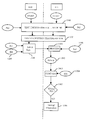
- Fig. 17 contains a flowchart illustrating an example of embodiment in which a time window ⁇ t is initiated at box 1700 in the system comprising the STB and the HD.
- a time window ⁇ t is initiated at box 1700 in the system comprising the STB and the HD.
- an occurrence of a mutual verification of identity is monitored at box 1701.
- the cooperation between the STB and the HD is interrupted in box 1703.
- the verification is performed in box 1704.
- the verification may for example comprise anyone of the described examples of embodiments described herein. If in box 1705 the verification fails, then co-operation between the STB and the HD is interrupted. In case the verification is successful, a new time window may be initiated.
- Fig. 18 illustrates an example embodiment for implementing a time window between the STB and the HD.
- a first time value ⁇ t 1 is generated in the STB in box 1800 and transmitted to the HD.
- a time window is triggered in box 1801 during which the occurrence of a mutual verification of identity between the STB and the HD is monitored in box 1802. If in box 1803 an attempt to perform a verification is detected, then it is checked if the attempt took place during the time window in box 1804. If the attempt took place outside of the time window, the cooperation between the STB and the HD is interrupted in box 1805. If no attempt to perform a mutual verification is detected in box 1803, then the cooperation between the STB and the HD is interrupted in box 1805.
- Fig. 19 illustrated a further example in which a time window is implemented. Boxes 1800 to 1804 in fig. 19 are the same as in Fig. 18. Following reception of the first time value in box 1801, a confirmation is sent to the STB in box 1900. On reception of the confirmation message in the STB, a further time window corresponding to the first time value is triggered in the STB in box 1901. After waiting during the further time window in box 1902, the STB starts a mutual verification of identity in box 1903. The start of a mutual verification is detected in the HD, and after verifications in boxes 1803 and 1804, the mutual verification of identity between the STB and the HD is performed in box 1904. If the mutual verification fails in box 1905, then the cooperation between the STB and the HD is interrupted. If the opposite case, a new time window may be generated as illustrated by arrow 1906
- a second time value may be generated in the HD, for example in box 1801, that defines a time interval corresponding to the time window, during which the monitoring of box 1802 takes place.
- Fig. 20 contains a flowchart illustrating an example of integrating the generation of a time window in a process of mutual verification.
- the first time value ⁇ t 1 is generated in box 2000 in the STB.
- the first time value ⁇ t 1 is subsequently hashed and signed using the private key Pr1, together in a message with the first identification ID1, in box 2001.
- the hashed and signed message is transmitted to the HD and processed in box 2002.
- the first time value ⁇ t 1 is extracted using the public key Pu1, and following the extraction a time window is triggered in box 2003.
- the HD may confirm reception of the first time value and the STB may wait for a determined time (not shown in Fig. 20) as described in the example from Fig. 19.
- the STB starts a process of mutual verification and a random message Rnd3 is generated in box 2006.
- the random message Rnd3 is transmitted to the HD, the HD detects a valid occurrence of the mutual verification of identity in boxes 1803 and 1804 if the detection occurs during the time window. Subsequently the random message Rnd3 is hashed and signed using the private key Pr2 and transmitted to the STB for further processing of the mutual verification of identity.
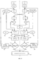
- Fig. 21 illustrates a general example of a method for securing a system comprising a STB and a HD.
- a random message Rnd1 in box 2100 is generated in box 2103 on the side of the STB and transmitted to the HD in box 2101.
- the random message Rnd1 from box 2101 is inserted into a message in box 2102.
- the message from box further comprises an identification ID2 which is stored in the HD and a second random message Rnd2.
- the identification ID2 may for example be a serial number of the HD.
- the random message Rnd2 is generated in the HD in box 2104.
- the message 2102 is hashed and signed in box 2105 using a private key Pr2 of the HD in box 2106.
- the hashed and signed message is transmitted to the SBT and processed in box 2107 using a public key Pu2 in box 2108 corresponding to the private key Pr2.
- the random message Rnd1 the identification ID2 and the random number Rnd2 are obtained in boxes 2109, 2110 and 2111.
- the latter boxes are represented in dotted lines to show that their content needs to be verified, since it is not yet established that the system comprising the STB and the HD is unchanged since the process of pairing.
- the random message Rnd1 form box 2109 is compared in box 2112 with the random message Rnd1 form box 2100. If in box 2113 it is found that the random messages from boxes 2100 and 2109 are different then an error is reported in box 2114, that may lead to interrupt cooperation between the STB and the HD.
- an identification ID2 stored in the STB is read in box 2115 and compared with the identification ID2 from box 2110 in a compare box 2116. If the identifications from boxes 2115 and 2110 are found to be different in box 2117, then an error is reported in box 2118.
- a message 2119 is created comprising the random message Rnd2 from box 2111, an identification ID1 and a first time value ⁇ t 1.
- the identification ID1 which is stored in the STB may for example be a serial number of the STB.
- the first time value ⁇ t 1 is generated in the STB in box 2120.
- the message 2119 is hashed and signed in box 2121 using a private key Pr1 from box 2122, and transmitted to the HD, where it is processed in box 2123 using a public key Pu1 from box 2124, which corresponds to the private key Pr1.
- the random message Rnd2 the identification ID1 and the first time value ⁇ t 1 are obtained as represented in dotted boxes respectively referenced with 2125, 2126 and 2127.
- the random message Rnd2 from box 2125 is compared in box 2128 with the random message Rnd2 which was generated in the HD in box 2104.
- a second time value ⁇ t 2 is generated in box 2134, as a function of the first time value ⁇ t 1 from box 2127.
- a confirmation for a receiving of the first time value ⁇ t 1 in box 2127 is generated and sent to the STB in box 2135.
- reception of a message from the STB is monitored in the HD during a time window lasting for the second time value ⁇ t 2.
- the confirmation of reception sent from box 2135 is received in box 2137, and triggers a wait cycle in box 2138 that lasts as long as the first time value ⁇ t 1.
- a process of mutual verification of identity is started in box 2139 on side of the STB, similar to the process starting with the generation of a random message in box 2103 and box 2100.
- the starting of the process in box 2139 triggers a message received status in box 2140, that on turn triggers the process of mutual verification of identify to start on side of the HD in box 2141.
- the key pairs (Pr1, Pu1) and (Pr2, Pu2), as well as the identifications ID1 and ID2 are stored in the STB and HD as appropriate during the process of pairing.
Landscapes
- Engineering & Computer Science (AREA)
- Computer Security & Cryptography (AREA)
- Theoretical Computer Science (AREA)
- Multimedia (AREA)
- Signal Processing (AREA)
- Computer Hardware Design (AREA)
- Software Systems (AREA)
- Physics & Mathematics (AREA)
- General Engineering & Computer Science (AREA)
- General Physics & Mathematics (AREA)
- Storage Device Security (AREA)
Priority Applications (3)
| Application Number | Priority Date | Filing Date | Title |
|---|---|---|---|
| EP02292028A EP1389750A1 (fr) | 2002-08-13 | 2002-08-13 | Securité d'un disc dur |
| PCT/EP2003/050370 WO2004017637A1 (fr) | 2002-08-13 | 2003-08-08 | Systeme servant a securiser un disque dur |
| AU2003262569A AU2003262569A1 (en) | 2002-08-13 | 2003-08-08 | Hard disk security |
Applications Claiming Priority (1)
| Application Number | Priority Date | Filing Date | Title |
|---|---|---|---|
| EP02292028A EP1389750A1 (fr) | 2002-08-13 | 2002-08-13 | Securité d'un disc dur |
Publications (1)
| Publication Number | Publication Date |
|---|---|
| EP1389750A1 true EP1389750A1 (fr) | 2004-02-18 |
Family
ID=30470333
Family Applications (1)
| Application Number | Title | Priority Date | Filing Date |
|---|---|---|---|
| EP02292028A Withdrawn EP1389750A1 (fr) | 2002-08-13 | 2002-08-13 | Securité d'un disc dur |
Country Status (3)
| Country | Link |
|---|---|
| EP (1) | EP1389750A1 (fr) |
| AU (1) | AU2003262569A1 (fr) |
| WO (1) | WO2004017637A1 (fr) |
Cited By (1)
| Publication number | Priority date | Publication date | Assignee | Title |
|---|---|---|---|---|
| US8108693B2 (en) | 2005-04-01 | 2012-01-31 | Ged-I Ltd. | Method for data storage protection and encryption |
Families Citing this family (6)
| Publication number | Priority date | Publication date | Assignee | Title |
|---|---|---|---|---|
| US9325944B2 (en) | 2005-08-11 | 2016-04-26 | The Directv Group, Inc. | Secure delivery of program content via a removable storage medium |
| US7992175B2 (en) | 2006-05-15 | 2011-08-02 | The Directv Group, Inc. | Methods and apparatus to provide content on demand in content broadcast systems |
| US8996421B2 (en) | 2006-05-15 | 2015-03-31 | The Directv Group, Inc. | Methods and apparatus to conditionally authorize content delivery at broadcast headends in pay delivery systems |
| US8775319B2 (en) | 2006-05-15 | 2014-07-08 | The Directv Group, Inc. | Secure content transfer systems and methods to operate the same |
| US9225761B2 (en) | 2006-08-04 | 2015-12-29 | The Directv Group, Inc. | Distributed media-aggregation systems and methods to operate the same |
| US9178693B2 (en) | 2006-08-04 | 2015-11-03 | The Directv Group, Inc. | Distributed media-protection systems and methods to operate the same |
Citations (4)
| Publication number | Priority date | Publication date | Assignee | Title |
|---|---|---|---|---|
| EP0398492A2 (fr) * | 1989-05-15 | 1990-11-22 | International Business Machines Corporation | Interface flexible pour les services d'authentification dans un système de traitement de données distribué |
| DE4138861A1 (de) * | 1991-11-26 | 1992-10-01 | Siemens Nixdorf Inf Syst | Verfahren zur gegenseitigen authentifikation eines elektronischen partners mit einem kommunikationssystem |
| GB2281991A (en) * | 1993-09-10 | 1995-03-22 | Icl Systems Ab | Authentication |
| EP0919929A1 (fr) * | 1997-06-18 | 1999-06-02 | Kabushiki Kaisha Optrom | Support de donnees avec circuit electronique et procede de gestion de ce support de donnees |
Family Cites Families (3)
| Publication number | Priority date | Publication date | Assignee | Title |
|---|---|---|---|---|
| JP2002503354A (ja) * | 1997-06-06 | 2002-01-29 | トムソン コンシユーマ エレクトロニクス インコーポレイテツド | 装置へのアクセスを管理する方法 |
| US7260719B1 (en) * | 1999-04-13 | 2007-08-21 | Sony Corporation | Information processing system, information processing method, and information processing device |
| US6477252B1 (en) * | 1999-08-29 | 2002-11-05 | Intel Corporation | Digital video content transmission ciphering and deciphering method and apparatus |
-
2002
- 2002-08-13 EP EP02292028A patent/EP1389750A1/fr not_active Withdrawn
-
2003
- 2003-08-08 AU AU2003262569A patent/AU2003262569A1/en not_active Abandoned
- 2003-08-08 WO PCT/EP2003/050370 patent/WO2004017637A1/fr not_active Application Discontinuation
Patent Citations (4)
| Publication number | Priority date | Publication date | Assignee | Title |
|---|---|---|---|---|
| EP0398492A2 (fr) * | 1989-05-15 | 1990-11-22 | International Business Machines Corporation | Interface flexible pour les services d'authentification dans un système de traitement de données distribué |
| DE4138861A1 (de) * | 1991-11-26 | 1992-10-01 | Siemens Nixdorf Inf Syst | Verfahren zur gegenseitigen authentifikation eines elektronischen partners mit einem kommunikationssystem |
| GB2281991A (en) * | 1993-09-10 | 1995-03-22 | Icl Systems Ab | Authentication |
| EP0919929A1 (fr) * | 1997-06-18 | 1999-06-02 | Kabushiki Kaisha Optrom | Support de donnees avec circuit electronique et procede de gestion de ce support de donnees |
Cited By (1)
| Publication number | Priority date | Publication date | Assignee | Title |
|---|---|---|---|---|
| US8108693B2 (en) | 2005-04-01 | 2012-01-31 | Ged-I Ltd. | Method for data storage protection and encryption |
Also Published As
| Publication number | Publication date |
|---|---|
| AU2003262569A1 (en) | 2004-03-03 |
| WO2004017637A1 (fr) | 2004-02-26 |
Similar Documents
| Publication | Publication Date | Title |
|---|---|---|
| JP4698106B2 (ja) | 送信された情報をコピー保護するシステム及び方法 | |
| US7146498B1 (en) | Computer and program recording medium | |
| US6069647A (en) | Conditional access and content security method | |
| KR101172093B1 (ko) | 디지털 오디오/비디오 데이터 처리 장치 및 액세스 제어방법 | |
| KR100966970B1 (ko) | 컨텐츠 방송용 보안 시스템에서 규정 비준수 키, 어플라이언스 또는 모듈의 폐기 리스트 갱신 방법 | |
| US6182215B1 (en) | Information devices which select and use one out of plurality of encryption utilization protocols for protecting copyrights of digital productions | |
| US7676042B2 (en) | Terminal apparatus, server apparatus, and digital content distribution system | |
| US20060005257A1 (en) | Encrypted contents recording medium and apparatus and method for reproducing encrypted contents | |
| US8392722B2 (en) | Digital cable system and method for protection of secure micro program | |
| US20070256141A1 (en) | Content distribution system | |
| JP3695992B2 (ja) | 放送受信装置及びコンテンツ利用制御方法 | |
| EP2113152B1 (fr) | Système d'accès conditionnel | |
| JP2010021875A (ja) | データ送信装置、データ受信装置、データ送信方法およびデータ受信方法 | |
| EP3414911B1 (fr) | Procédé et dispositif pour identifier un dispositif périphérique à partir d'un contenu numérique | |
| US20060045478A1 (en) | Method and apparatus for transmitting and receiving protected contents at home | |
| KR20040088530A (ko) | 제1 도메인용으로 암호화한 데이터를 제2 도메인에 속한네트워크에서 처리하기 위한 디바이스 및 그 데이터를전송하는 방법 | |
| EP1389750A1 (fr) | Securité d'un disc dur | |
| US8103001B2 (en) | Method for verifying rights contained in a security module | |
| TWI481255B (zh) | 利用控制字加擾多媒體內容之接收方法 | |
| JP2010097502A (ja) | 暗号化・復号システム、暗号化装置、復号装置、および暗号化・復号方法 | |
| JP5033090B2 (ja) | 認証情報生成装置、コンテンツ配信装置、受信装置およびセキュリティモジュール | |
| JP2009123002A (ja) | 再生装置、機器認証確認方法及びプログラム | |
| JP2007324896A (ja) | 受信装置、casモジュール | |
| JP2001251290A (ja) | データ放送システムとコンテンツの配信、蓄積、再生方法 | |
| JP2007036380A (ja) | 受信装置、casモジュール、配信方法 |
Legal Events
| Date | Code | Title | Description |
|---|---|---|---|
| PUAI | Public reference made under article 153(3) epc to a published international application that has entered the european phase |
Free format text: ORIGINAL CODE: 0009012 |
|
| AK | Designated contracting states |
Kind code of ref document: A1 Designated state(s): AT BE BG CH CY CZ DE DK EE ES FI FR GB GR IE IT LI LU MC NL PT SE SK TR |
|
| AX | Request for extension of the european patent |
Extension state: AL LT LV MK RO SI |
|
| RAP1 | Party data changed (applicant data changed or rights of an application transferred) |
Owner name: THOMSON LICENSING S.A. |
|
| AKX | Designation fees paid | ||
| REG | Reference to a national code |
Ref country code: DE Ref legal event code: 8566 |
|
| STAA | Information on the status of an ep patent application or granted ep patent |
Free format text: STATUS: THE APPLICATION IS DEEMED TO BE WITHDRAWN |
|
| 18D | Application deemed to be withdrawn |
Effective date: 20040819 |