EP1388663B1 - Stirling engine - Google Patents
Stirling engine Download PDFInfo
- Publication number
- EP1388663B1 EP1388663B1 EP03017521A EP03017521A EP1388663B1 EP 1388663 B1 EP1388663 B1 EP 1388663B1 EP 03017521 A EP03017521 A EP 03017521A EP 03017521 A EP03017521 A EP 03017521A EP 1388663 B1 EP1388663 B1 EP 1388663B1
- Authority
- EP
- European Patent Office
- Prior art keywords
- displacer
- casing
- stirling engine
- power piston
- chamber
- Prior art date
- Legal status (The legal status is an assumption and is not a legal conclusion. Google has not performed a legal analysis and makes no representation as to the accuracy of the status listed.)
- Expired - Fee Related
Links
Images


Classifications
-
- F—MECHANICAL ENGINEERING; LIGHTING; HEATING; WEAPONS; BLASTING
- F02—COMBUSTION ENGINES; HOT-GAS OR COMBUSTION-PRODUCT ENGINE PLANTS
- F02G—HOT GAS OR COMBUSTION-PRODUCT POSITIVE-DISPLACEMENT ENGINE PLANTS; USE OF WASTE HEAT OF COMBUSTION ENGINES; NOT OTHERWISE PROVIDED FOR
- F02G1/00—Hot gas positive-displacement engine plants
- F02G1/04—Hot gas positive-displacement engine plants of closed-cycle type
- F02G1/043—Hot gas positive-displacement engine plants of closed-cycle type the engine being operated by expansion and contraction of a mass of working gas which is heated and cooled in one of a plurality of constantly communicating expansible chambers, e.g. Stirling cycle type engines
- F02G1/0435—Hot gas positive-displacement engine plants of closed-cycle type the engine being operated by expansion and contraction of a mass of working gas which is heated and cooled in one of a plurality of constantly communicating expansible chambers, e.g. Stirling cycle type engines the engine being of the free piston type
-
- F—MECHANICAL ENGINEERING; LIGHTING; HEATING; WEAPONS; BLASTING
- F02—COMBUSTION ENGINES; HOT-GAS OR COMBUSTION-PRODUCT ENGINE PLANTS
- F02G—HOT GAS OR COMBUSTION-PRODUCT POSITIVE-DISPLACEMENT ENGINE PLANTS; USE OF WASTE HEAT OF COMBUSTION ENGINES; NOT OTHERWISE PROVIDED FOR
- F02G1/00—Hot gas positive-displacement engine plants
- F02G1/04—Hot gas positive-displacement engine plants of closed-cycle type
- F02G1/043—Hot gas positive-displacement engine plants of closed-cycle type the engine being operated by expansion and contraction of a mass of working gas which is heated and cooled in one of a plurality of constantly communicating expansible chambers, e.g. Stirling cycle type engines
- F02G1/044—Hot gas positive-displacement engine plants of closed-cycle type the engine being operated by expansion and contraction of a mass of working gas which is heated and cooled in one of a plurality of constantly communicating expansible chambers, e.g. Stirling cycle type engines having at least two working members, e.g. pistons, delivering power output
-
- F—MECHANICAL ENGINEERING; LIGHTING; HEATING; WEAPONS; BLASTING
- F01—MACHINES OR ENGINES IN GENERAL; ENGINE PLANTS IN GENERAL; STEAM ENGINES
- F01L—CYCLICALLY OPERATING VALVES FOR MACHINES OR ENGINES
- F01L9/00—Valve-gear or valve arrangements actuated non-mechanically
- F01L9/20—Valve-gear or valve arrangements actuated non-mechanically by electric means
- F01L9/21—Valve-gear or valve arrangements actuated non-mechanically by electric means actuated by solenoids
- F01L2009/2105—Valve-gear or valve arrangements actuated non-mechanically by electric means actuated by solenoids comprising two or more coils
Definitions
- the present invention relates to a Stirling engine of the displacer type capable of preventing leakage of an operation gas, according to the preamble of claim 1.
- a stirling machine is disclosed in the US 4 215 548.
- Such a Stirling engine of the displacer type usually comprises a casing, a displacer arranged in the casing so as to slide, an expansion chamber and an operation chamber into which, and from which, an operation gas flows with the operation of the displacer, a power piston operated by an electromagnetic means in response to a change in the pressure of the operation gas in the operation chamber, and an operation rod that is coupled to the displacer to operate the displacer at a predetermined timing.
- the power piston is operated in response to a change in the pressure in the operation chamber with the expansion and contraction as the operation gas is heated and cooled.
- the operation gas used for the Stirling engine is the one having a small specific heat, such as hydrogen or helium, for improving the heat efficiency.
- the gas having a small specific heat, such as hydrogen or helium, used as an operation gas for the Stirling engine is prone to leak through the sliding portions because molecules of the gas are small in size, and hence, the leakage of the operation gas cannot be prevented by the sealing that is usually used for the sliding portions.
- the operation rod coupled to the displacer is arranged penetrating through the casing. It is therefore important to prevent the operation gas from leaking through the sliding portion that penetrates through.
- a system is contrivable in which the displacer is formed of a sealed container, and it is used as a free piston and is operated by utilizing a gas spring or gravity.
- the stilling engine comprises the features of claim 1 or 2.
- the Stirling engine is provided with a casing, a displacer arranged in the casing so as to slide, an expansion chamber and an operation chamber into which, and from which, an operation gas flows with the operation of the displacer, and a power piston that is operated in response to a change in the pressure of the operation gas in the operation chamber.
- the Stirling engine further comprises a displacer operation means having a moving yoke disposed in the displacer, and a pair of electromagnetic solenoids disposed to surround the moving yoke and juxtaposed to each other in the axial direction in the casing, a power piston position detection means for detecting the operation position of the power piston, and a control means for control to switch over the excitation of the pair of electromagnetic solenoids of the displacer operation means based on a detection signal from the power piston position detection means.
- a Stirling engine comprising a casing, a displacer arranged in the casing so as to slide, an expansion chamber and an operation chamber into which, and from which, an operation gas flows with the operation of the displacer, and a power piston that is operated in response to a change in the pressure of the operation gas in the operation chamber
- the Stirling engine further comprises a displacer operation means having a moving magnet disposed an the displacer, a fixed cylindrical yoke disposed in the casing and arranged to surround the moving magnet, and a pair of coils disposed on the inside of the fixed yoke, a power piston position detection means for detecting the operation position of the power piston, and a control means for controlling to switch over the direction of an electric current supplied to the pair of coils of the displacer operation means based on a detection signal from the power piston position detection means.
- the Stirling engine of the embodiment shown in Fig. 1 has a cylindrical casing 2.
- the casing 2 is made of a nonmagnetic material such as an aluminum alloy or the like, and comprises a central slide unit 21, a heating chamber 22 formed on the left side of the central slide unit 21 in the drawing, and a cooling chamber 23 formed on the right side of the central slide unit 21 in the drawing.
- the casing 2 is provided with a heated fluid inlet 221 and a heated fluid outlet 222 opened to the heating chamber 22, and with a cooled fluid inlet 231 and a cooled fluid outlet 232 opened to the cooling chamber 23.
- a slide cylinder 3 made of a nonmagnetic material is disposed on the inner peripheral surface of the central slide unit 21 of the casing 2 so as to slide in the axial direction.
- a displacer 4 is arranged passing through the slide cylinder 3 so as to slide in the axial direction.
- the displacer 4 is made of a nonmagnetic material in a cylindrical shape, and has, in its inside, a regenerator 5 constituted by alternately superposing a heat-insulating ring made of a heat-insulating material ana a wire gauze.
- An expansion bellows 7 is arranged in the heating chamber 22.
- the expansion bellows 7 is attached at its one end to a left end of the slide cylinder 3 in the drawing and is attached at its other end to a left end wall 24 of the casing 2.
- an expansion chamber 71 that is defined by the expansion bellows 7, the slide cylinder 3 and the left end wall 24 and is communicated with the regenerator 5 disposed in the cylindrical displacer 4.
- a contraction bellows 8 is arranged in the cooling chamber 23.
- the contraction bellows 8 is attached at its one end to a right end of the slide cylinder 3 in the drawing and is attached at its other end to a power piston 9.
- an operation chamber 81 that is defined by the contraction bellows 8 and by the slide cylinder 3, and is communicated with the regenerator 5 disposed in the cylindrical displacer 4.
- An operation gas having a small specific heat, such as hydrogen or helium, is sealed in the expansion chamber 71, in the operation chamber 81 and in the cylindrical displacer 4.
- a power take-off shaft 91 which is arranged penetrating through the right end wall 25 of the casing 2.
- the Stirling engine of the embodiment shown in Fig. 1 is provided with a displacer operation means 10 for periodically operating the displacer 4.
- the displacer operation means 10 is constituted by a moving yoke 11 disposed on the outer peripheral surface at the central portion of the displacer 4, and a pair of electromagnetic solenoids 12 and 13 arranged to surround the moving yoke 11 and juxtaposed to each other in the axial direction on the inner peripheral side of the casing 2.
- the moving yoke 11 is made of a magnetic material in a cylindrical shape, and is disposed in an annular fitting groove 41 formed in the outer peripheral surface of the displacer 4.
- the pair of electromagnetic solenoids 12 and 13 are constituted by exciting coils 122 and 132 wound on the bobbins 121 and 131, and fixed yokes 123 and 133 arranged covering both sides of the exciting coils 122 and 132 in the axial direction and covering the outer peripheral sides thereof.
- the pair of electromagnetic solenoids 12 and 13 are disposed in annular fitting grooves 26 and 27 formed in the inner peripheral surface of the casing 2.
- the exciting coils 122 and 132 are connected to a power source 183 via switches 181 (SW1) and 182 (SW2) of a drive circuit 18.
- the fixed yokes 123 and 133 are constituted by annular yoke pieces 123a, 123b and 133a, 133b made of a magnetic material disposed on both sides of the exciting coils 122 and 132 in the axial direction, and cylindrical yoke pieces 123c and 133c made of a magnetic material disposed on the outer peripheral side of the exciting coils 122 and 132.
- the switch 181 (SW1) when the switch 181 (SW1) is turned on, an electric current is supplied to the exciting coil 122 of one electromagnetic solenoid 12, whereby the electromagnetic solenoid 12 is exited to move the displacer 4 toward the right in Fig. 1.
- the switch 182 (SW2) is turned on, on the other hand, an electric current is supplied to the exciting coil 132 of the electromagnetic solenoid 13, whereby the electromagnetic solenoid 13 is excited to move the displacer 4 toward the left in Fig. 1.
- the Stirling engine of the embodiment shown in Fig. 1 is provided with a power piston position detection means 16 for detecting the operation position of the power piston 9.
- the power piston position detection means 16 is constituted by a stroke sensor disposed opposite to the power take-off shaft 91 coupled to the power piston 9, and sends a detection signal to a control means 17 that will be described later. Description will be made of the output value of the stroke sensor that is the power piston position detection means 16, with reference to Fig. 2.
- the abscissa represents the stroke of the power piston 9, that is, the power take-off shaft 91, and the ordinate represents the voltage.
- Fig. 2 the abscissa represents the stroke of the power piston 9, that is, the power take-off shaft 91, and the ordinate represents the voltage.
- the stroke sensor produces a voltage that varies in proportion to the stroke of the power piston 9, that is, the power take-off shaft 91.
- L1 represents the full-stroke position (bottom dead center) on the return side
- L10 represents the full-stroke position (top dead center) on the feed side.
- the control means 17 is constituted by a microcomputer, and has a central processing unit (CPU) for processing the operation according to a control program, a read-only memory (ROM) for storing the control program, and a random access memory (RAM) for storing the results of operation.
- CPU central processing unit
- ROM read-only memory
- RAM random access memory
- control means 17 Based on an operation position signal of the power piston 9 detected by the power piston position detection means 16, the control means 17 sends a control signal to the switches 181 (SW1) and 182 (SW2) of the drive circuit 18 for operating the pair of electromagnetic solenoids 12 and 13 that constitute the displacer operation means 10.
- Fig. 4 (a) shows an end of contraction where the power piston 9 is at the left end position in the drawing, i.e., at the full-stroke position (bottom dead center) on the return side, and the displacer 4 is also at the left end position, i.e., at the full-stroke position (bottom dead center) on the return side.
- the control means 17 controls to drive the displacer operation means 10 so as to move the displacer 4 toward the right in the drawing (step S1).
- the control means 17 turns the switch 182 (SW2) of the drive circuit 18 off, and turns the switch 181 (SW1) on, to supply an electric current to the exciting coil 122 of the one electromagnetic solenoid 12 constituting the.displacer operation means 10 to excite the electromagnetic solenoid 12.
- the displacer 4 moves toward the right as shown in Fig. 4(b).
- the operation gas in the operation chamber 81 flows into the expansion chamber 71 through the regenerator 5 disposed in the cylindrical displacer 4.
- the operation gas cooled in the operation chamber 81 is heated by heat exchange caused at the time when it passes through the regenerator 5.
- a state where the displacer 4 has moved toward the right by a predetermined amount is the time of starting expansion. From this moment, the operation gas that has flowed into the expansion chamber 71 undergoes the expansion by being heated by the heated fluid introduced into the heating chamber 22. As a result, the displacer 4 has its expansion bellows 7 expanded as shown in Fig. 4(c), whereby the slide cylinder 3 and the contraction bellows 8 move toward the right as shown in Fig. 4(c), and the displacer 4 is moved toward the right.
- the power piston 9 is moved to the right end position, i.e., to the full-stroke position (top dead center) on the feed side, and the displacer 4, too, is moved to the right end position, i.e., to the full-stroke position (top dead center) on the feed side.
- step S1 the control means 17 proceeds to step S2 to check, based on a detection signal from the power piston position detection means 16, whether the stroke position L of the power piston 9, i.e., of the power take-off shaft 91 is larger than a stroke position L9 which is a threshold value smaller, by a predetermined amount, than the full-stroke position (top dead center) L10 on the feed side (L > L9).
- step S3 the control means 17 proceeds to step S3 to check whether the stroke position L of the power piston 9, i.e., of the power take-off shaft 91 is smaller than a stroke position L2 which is a threshold value larger, by a predetermined amount, than the full-stroke position (bottom dead center) L1 on the return side (L ⁇ L2). This time, the power piston 9 is moved toward the feed side and hence, it does not happen that the stroke position L is smaller than L2. Accordingly, the control means 17 returns to step S2.
- the control means 17 judges that the power piston 9 has exceeded the position which is smaller, by a predetermined amount, than the position at the end of expansion shown in Fig 4(c).
- the control means 17, then, proceeds to step S4 to drive the displacer operation means 10 so as to move the displacer 4 toward the left in the drawing.
- the control means 17 turns the switch 181 (SW1) of the drive circuit 18 off, and turns the switch 182 (SW2) on, to supply an electric current to the exciting coil 132 of the other electromagnetic solenoid 13 constituting the displacer operation means 10 thereby to excite the electromagnetic solenoid 13.
- the displacer 4 moves toward the left as shown in Fig. 4(d).
- the state shown in Fig. 4 (d) is the time of starting contraction where the displacer 4 reaches the left end position, i.e., reaches the full-stroke position (bottom dead center) on the return side.
- the power piston 9 is located at the right end position in the drawing, i.e., located at the full-stroke position (top dead center) on the feed side. From the state shown in Fig.
- the operation gas in the operation chamber 81 contracts by being cooled by the cold gas introduced into the cooling chamber 23.
- the contraction bellows 8 forming the operation chamber 81 contracts and at the end of contraction shown in Fig . 4 (a), the power piston 9 is moved to the left end position in the drawing, i.e., to the full-stroke position (bottom dead center) on the return side.
- the control means After the displacer operation means 10 is driven at step S4 to move the displacer 4 toward the left in the drawing as described above, the control means returns back to step S2 to check whether the stroke position L of the power piston 9, i. e. , of the power take-off shaft 91 is larger than a stroke position L9 which is a threshold value smaller, by a predetermined amount, than the full-stroke position (top dead center) L10 on the feed side. This time, the power piston 9 is moved toward the return side, and it does not happen that the stroke position L is larger than L9.
- the control means 17 proceeds to step S3 to check whether the stroke position L of the power piston 9, i.e., of the power take-off shaft 91 is smaller than a stroke position L2 which is a threshold value larger, by a predetermined amount, than the full-stroke position (bottom dead center) L1 on the return side.
- a stroke position L2 which is a threshold value larger, by a predetermined amount, than the full-stroke position (bottom dead center) L1 on the return side.
- the stroke position L is not smaller than L2
- the control means 17 judges that the power piston 9 does not yet reach L2.
- the control means 17, therefore, returns back to step S2 to repeat steps S2 and S3.
- the stroke position L of the power piston 9 is smaller than L2 at step S3, the control means 17 judges that the power piston 9 has exceeded L2.
- the control means 17, therefore, proceeds to step S5 to turn the switch 182 (SW2) of the drive circuit 18 off and the switch.181 (SW1) on to move the displacer 4 toward the right in the drawing, and supplies an electric current to the exciting coil 122 of the one electromagnetic solenoid 12 to excite the electromagnetic solenoid 12.
- the above cycle is repeated to reciprocatingly move the power piston 9, i.e., the power take-off shaft 91. Therefore, when the power take-off shaft 91 is coupled to a crank shaft via a suitable connection rod, the crank shaft can be rotated.
- the above-mentioned mechanism of the Stirling engine can be used for actuating the to-be-operated member to the two positions by so controlling as to stop the displacer 4 at the full-stroke position (top dead center) on the feed side and at the full-stroke position (bottom dead center) on the return side, and to stop the power piston 9, i.e., the power take-off shaft 91 at the full-stroke position (top dead center) L1 on the feed side and at the full-stroke position (bottom dead center) L1 on the return side.
- the switch 181 (SW1) and the switch 182 (SW2) of the drive circuit 18 may be operated by hand, or a switching-over signal may be input to the control means 17.
- a means for inputting switching-over signals to the switch 181 (SW1) and the switch 182 (SW2) or to the control means 17 work as a switching-over means for switching over the excitation of the pair of electromagnetic solenoids 12 and 13.
- the displacer operation means 10 for operating the displacer 4 is constituted by the moving yoke 11 disposed in the displacer 4 and by the pair of electromagnetic solenoids 12 and 13 disposed to surround the moving yoke 11 and juxtaposed in the axial direction on the inside of the casing 2. Therefore, the rod for driving the displacer 4 does not penetrate through the casing 2 with the consequence that the leakage of the operation gas can be prevented. Further, the operation cycle of the displacer 4 can be easily changed by suitably controlling the timing for turning on/off the switch 181 (SW1) and the switch 182 (SW2) of the drive circuit 18, namely, for suitably controlling the timing for exciting the pair of electromagnetic solenoids 12 and 13. There is no limitation, besides, on the direction for installing the casing 2.
- the slide cylinder 3 is formed in an extended manner instead of employing the contraction bellows 8 arranged in the cooling chamber 23 in the embodiment shown in Fig. 1, and the power piston 9 is attached to the right end of the slide cylinder 3 in the drawing. Then, cooling fins 31 are mounted on the outer periphery at the right end of the slide cylinder 3 in the drawing.
- the Stirling engine shown in Fig. 6 is the one of the type in which the displacer and the power piston are not arranged on the same axis, and to which the present invention is applied. Namely, in the Stirling engine shown in Fig. 6, a power cylinder 900a is arranged at right angles with a casing 200a, and a power piston 9a is arranged in the power cylinder 900a so as to slide therein.
- the casing 200a is made of a metallic material such as an aluminum alloy or the like and is formed with its both ends closed.
- heating fins 201a are formed on the outer peripheral surface at the upper end thereof, and cooling fins 202a are formed on the outer peripheral surface of the lower half portion thereof.
- the displacer 4 is arranged so as to move up and down in the drawing. Due to the displacer 4, therefore, the interior of the casing 200a is divided into an expansion chamber 203a of the upper side in the drawing and a cooling chamber 204a of the lower side in the drawing.
- the cooling chamber 204a is communicated, via a passage 205a, with an operation chamber 81a formed by the power cylinder 900a and the power piston 9a.
- the moving yoke 11 of the displacer operation means 10 that periodically operates the displacer 4 is arranged on the outer peripheral surface at the central portion of the displacer 4, and the pair of electromagnetic solenoids 12 and 13 are arranged in the casing 200a.
- the displacer operation means 10 for operating the displacer 4 is constituted by the moving yoke 11 disposed in the displacer 4 and the pair of electromagnetic solenoids 12 and 13 disposed in the casing 200a. Therefore, the rod for driving the displacer 4 does not penetrate through the casing 200a with the consequence that the leakage of the operation gas can be prevented.
- the operation cycle of the displacer 4 can be easily changed by suitably controlling the timing for supplying an electric current to the exciting coils 122 and 132 of the pair of electromagnetic solenoids 12 and 13, like in the above-mentioned embodiments. There is no limitation, besides, on the direction for installing the casing 200a.
- the displacer operation means for operating the displacer is constituted by the moving yoke disposed in the displacer and the pair of electromagnetic solenoids disposed to surround the moving yoke in the casing and juxtaposed to each other in the axial direction. Therefore, the rod for driving the displacer does not penetrate through the casing with the consequence that the leakage of the operation gas can be prevented. Further, the displacer operation means is equipped with a starter function. Accordingly, there is no need of separately providing the starter mechanism. The operation cycle of the displacer can be easily changed by suitably controlling the timing for exciting the pair of electromagnetic solenoids.
- the displacer is instantaneously switched over by the electromagnetic force of the displacer operation means and hence, has higher heat efficiency than that of the one of the crank shaft-coupling type.
- the Stirling engine of the fourth embodiment shown in Fig. 7 is different in only the constitution of the displacer operation means 10 in the Stirling engine of the first embodiment shown in Fig 1. In other respects, however, the constitution is substantially the same as those of the first embodiment. Therefore, the same members as the constituent members of the of the first embodiment are denoted by the same reference numerals, but their description is not repeated.
- the displacer operation means 10A constituting the Stirling engine of the fourth embodiment shown in Fig. 7 comprises a moving magnet 11A disposed on the outer peripheral surface at the central portion of the displacer 4, a fixed cylindrical yoke 12A disposed on the inside of the casing 2 to surround the moving magnet 11A, and a pair of coils 13A and 14A that are juxtaposed to each other in the axial direction and disposed on the inside of the fixed yoke 12A.
- the moving magnet 11A is constituted by an annular permanent magnet 111A mounted on the outer peripheral surface of the displacer 4 and having magnetic poles on both end surfaces thereof in the axial direction, and a pair of moving yokes 112A and 113A disposed on the outer sides of the permanent magnet 111A in the axial direction.
- the permanent magnet 111A in the illustrated embodiment has its right end surface magnetized to the N-pole in Fig 7 and has its left end surface magnetized to the S-pole in Fig. 7.
- the pair of moving yokes 112A and 113A are formed in an annular shape by using a magnetic material.
- the thus constituted moving magnet 11A is disposed in an annular fitting groove 41 formed in the outer peripheral surface of the displacer 4.
- the fixed yoke 12A is made of a magnetic material in a cylindrical shape, and is disposed in an annular fitting groove 26 formed in the inner peripheral surface of the casing 2.
- a pair of coils 13A and 14A are arranged on the inside of the fixed yoke 12A.
- the pair of coils 13A and 14A are wound reversely to each other on a bobbin 15A made of a nonmagnetic material such as a synthetic resin or the like and mounted along the inner periphery of the fixed yoke 12A.
- the pair of coils 13A and 14A are controlled to switch over the direction of applying an electric current by a control means that will be described later.
- the displacer operation means 10A constituted by the moving magnet 11A, fixed yoke 12A and pair of coils 13A and 14A, operates based on the principle of a linear motor. The operation will be described below with reference to Fig. 8.
- a magnetic circuit is formed, as shown in Figs. 8(a) and 8(b) passing through the N-pole of the permanent magnet 111A, one moving yoke 112A, one coil 13A, fixed yoke 12A, other coil 14A, other moving yoke 113A and S-pole of the permanent magnet 111A.
- the moving magnet 11, i.e., the displacer 4 produces a thrust toward the right as indicated by an arrow in Fig. 8(a) according to Fleming's left-hand rule.
- the Stirling engine of the embodiment shown in Fig. 7 is provided with a power piston position detection means 16A for detecting the operation position of the power piston 9.
- the power piston position detection means 16A is constituted in the same manner as the power piston position detection means 16 of the above-mentioned first embodiment, and has output characteristics as shown in Fig. 2 above.
- the power piston position detection means 16A sends a detection signal to the control means 17A.
- the control means 17A is constituted by a microcomputer and has a central processing unit (CPU) for processing the operation according to a control program, a read-only memory (ROM) for storing the control program, and a random access memory (RAM) for storing the results of operation. Based on an operation position signal of the power piston 9 detected by the power piston position detection means 16A, the control means 17A sends a control signal to the pair of coils 13A and 14A constituting the displacer operation means 10A.
- CPU central processing unit
- ROM read-only memory
- RAM random access memory
- Fig. 10 (a) shows an end of contraction where the power piston 9 is at the left end position in the drawing, i.e., at the full-stroke position (bottom dead center) on the return side, and the displacer 4 is also at the left end position, i.e., at the full-stroke position (bottom dead center) on the return side.
- the control means 17A controls to drive the displacer operation means 10A so as to move the displacer 4 toward the right in the drawing (step P1) . That is, the control means 17A controls to supply electric currents to the pair of coils 13A and 14A constituting the displacer operation means 10A in the opposite directions as shown in Fig . 8 (a).
- the moving magnet 11A i.e., the displacer 4 moves toward the right as shown in Fig. 10 (b).
- the operation gas in the operation chamber 81 flows into the expansion chamber 71 through the regenerator 5 disposed in the cylindrical displacer 4.
- the operation gas cooled in the operation chamber 81 is heated by heat exchange caused at the time where it passes through the regenerator 5.
- a state where the displacer 4 has moved toward the right by a predetermined amount is the time of starting expansion. From this moment, the operation gas that has flowed into the expansion chamber 71 undergoes the expansion by being heated by the heated fluid introduced into the heating chamber 22.
- the displacer 4 has its expansion bellows 7 expanded as shown in Fig 10(c), whereby the slide cylinder 3 and the contraction bellows 8 move toward the right in the drawing, and the displacer 4 moves toward the right.
- the power piston 9 is moved to the right end position, i.e., to the full-stroke position (top dead center) on the feed side, and the displacer 4, too, is moved to the right end position, i.e., to the full-stroke position (top dead center) on the feed side.
- step P2 the control means 17A proceeds to step P2 to check, based on a detection signal from the power piston position detection means 16A, whether the stroke position L of the power piston 9, i.e., of the power take-off shaft 91 is larger than a stroke position L9 which is a threshold value smaller, by a predetermined amount, than the full-stroke position (top dead center) L10 on the feed side (L > L9).
- step P3 the control means 17A proceeds to step P3 to check whether the stroke position L of the power piston 9, i.e., of the power take-off shaft 91 is smaller than a stroke position L2 which is a threshold value larger, by a predetermined amount, than the full-stroke position (bottom dead center) L1 on the return side (L ⁇ L2). This time, the power piston 9 is moved toward the feed side and hence, it does not happen that the stroke position L is smaller than L2. Accordingly, the control means 17A returns to the step P2.
- the control means 17A judges that the power piston 9 has exceeded the position which is smaller, by a predetermined amount, than the position at the end of expansion shown in Fig 10(c).
- the control means 17A proceeds to step P4 to drive the displacer operation means 10A so as to move the displacer 4 toward the left in the drawing.
- the control means 17A controls to supply electric currents to the pair of coils 13A and 14A constituting the displacer operation means 10A in the opposite directions shown in Fig. 2 (b).
- the moving magnet 11A i.e., the displacer 4 moves toward the left as shown in Fig. 10(d).
- the state shown in Fig. 10 (d) is the time of starting contraction where the displacer 4 reaches the left end position, i.e., reaches the full-stroke position (bottom dead center) on the return side.
- the power piston 9 is located at the right end position in the drawing, i.e., located at the full-stroke position (top dead center) on the feed side. From the state shown in Fig.
- the operation gas in the operation chamber 81 contracts by being cooled by the cold gas introduced into the cooling chamber 23.
- the contraction bellows 8 forming the operation chamber 81 contracts, and at the end of contraction shown in Fig. 10 (a), the power piston 9 is moved to the left end position in the drawing, i.e., to the full-stroke position (bottom dead center) on the return side.
- the control means After the displacer operation means 10A is driven at step P4 to move the displacer 4 toward the left in the drawing as described above, the control means returns back to step P2 to check whether the stroke position L of the power piston 9, i . e. , of the power take-off shaft 91 is larger than a stroke position L9 which is a threshold value smaller, by a predetermined amount, than the full-stroke position (top dead center) L10 on the feed side. This time, the power piston 9 is moved toward the return side, and it does not happen that the stroke position L is larger than L9. Accordingly, the control means 17A proceeds to step P3 to check whether the stroke position L of the power piston 9, i.e.
- a stroke position L2 which is a threshold value larger, by a predetermined amount, than the full-stroke position (bottom dead center) L1 on the return side.
- the control means 17A judges that the power piston 9 does not yet reach L2.
- the control means 17A returns back to step P2 to repeat steps P2 and P3.
- the stroke position L of the power piston 9 is smaller than L2 at step P3, the control means 17A judges that the power piston 9 has exceeded L2.
- the control means 17A proceeds to step P5 to control to supply electric currents to the pair of coils 13A and 14A in the opposite directions as shown in Fig. 8(a) to drive the displacer operation means 10A so as to move the displacer 4 toward the right in the drawing.
- the above cycle is repeated to reciprocatingly move the power piston 9, i.e., the power take-off shaft 91. Therefore, when the power take-off shaft 91 is coupled to a crank shaft through a suitable connection rod, the crank shaft can be rotated.
- the mechanism of the Stirling engine can be used as the actuator for actuating the to-be-operated member to the two positions by so controlling as to stop the displacer 4 at the full-stroke position (top dead center) on the feed side and at the full-stroke position (bottom dead center) on the return side and to stop the power piston 9, i.e., the power take-off shaft 91 at the full-stroke position (top dead center) L1 on the feed side and at the full-stroke position (bottom dead center) L1 on the return side.
- a switching-over signal may be input to the control means 17A.
- a means for inputting the switching-over signal to the control means 17A works as a switching-over means for switching over the directions of electric currents supplied to the pair of coils 13A and 14A.
- the displacer operation means 10A for operating the displacer 4 is constituted by the moving magnet 11A disposed in the displacer 4, the fixed cylindrical yoke 12A disposed to surround the moving-magnet 11A on the inside of the casing 2 and the pair of coils 13A and 14A juxtaposed in the axial direction on the inside of the fixed yoke 12A. Therefore, the rod for driving the displacer 4 does not penetrate through the casing 2 and hence, a sealed container can be formed and the leakage of the operation gas can be prevented. Further, the operation cycle of the displacer 4 can be easily changed by suitably controlling the timing for supplying the electric power to the pair of coils 13A and 14A. There is no limitation, besides, on the direction for arranging the casing 2.
- the slide cylinder 3 is formed in an extended manner instead of employing the contraction bellows 8 arranged in the cooling chamber 23 in the embodiment shown in Fig. 7, and the power piston 9 is attached to the right end of the slide cylinder 3 in the drawing. Then, cooling fins 31 are mounted on the outer periphery at the right end of the slide cylinder 3 in the drawing.
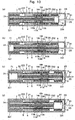
- the Stirling engine shown in Fig. 12 is the one of the type in which the displacer and the power piston are not arranged on the same axis, and to which the present invention is applied.
- a power cylinder 900A is arranged at right angles with a casing 200A, and a power piston 9A is arranged in the power cylinder 900A so as to slide therein.
- the casing 200A is made of a metallic material such as an aluminum alloy or the like and is formed with its both ends closed.
- heating fins 201A are formed on the outer peripheral surface at the upper end thereof, and cooling fins 202A are formed on the outer peripheral surface of the lower half portion thereof.
- the displacer 4 is arranged so as to move up and down in the drawing. Due to the displacer 4, therefore, the interior of the casing 200A is divided into an expansion chamber 203A of the upper side in the drawing and a cooling chamber 204A of the lower side in the drawing.
- the cooling chamber 204A is communicated, via a passage 205A, with an operation chamber 81A formed by the power cylinder 900A and the power piston 9A.
- the moving magnet 11A of the displacer operation means 10A which periodically operates the displacer 4 is arranged on the outer peripheral surface at the central portion of the displacer 4, and the fixed yoke 12A as well as the pair of coils 13A and 14A are arranged in the casing 200A.
- the displacer operation means 10A for periodically operating the displacer 4 is constituted by the moving magnet 11A disposed in the displacer 4, the fixed yoke 12A disposed in the casing 200A, and the pair of coils 13A and 14A. Therefore, the rod for driving the displacer 4 does not penetrate through the casing 200A with the consequence that the leakage of the operation gas can be prevented.
- the operation cycle of the displacer 4 can be easily changed by suitably controlling the timing for supplying an electric power to the pair of coils 13A and 14A, like in the above-mentioned embodiments. There is no limitation, besides, on the direction for installing the casing 200A.
- the displacer operation means for operating the displacer is constituted by the moving magnet disposed in the displacer, the fixed cylindrical yoke disposed in the casing to surround the moving magnet and the pair of coils arranged inside the fixed yoke. Therefore, the rod for driving the displacer does not penetrate through the casing and hence, a sealed container can be formed and the leakage of the operation gas can be prevented. Further, the displacer operation means is equipped with a starter function. Accordingly, there is no need of separately providing the starter mechanism. The operation cycle of the displacer can be easily changed by suitably controlling the timing for supplying the electric power to the pair of coils.
- the displacer is instantaneously switched over by switching over the electric currents supplied to the pair of coils of the displacer operation means and hence, has higher neat efficiency than that of the one of the crank shaft-coupled type.
Landscapes
- Engineering & Computer Science (AREA)
- Chemical & Material Sciences (AREA)
- Combustion & Propulsion (AREA)
- Mechanical Engineering (AREA)
- General Engineering & Computer Science (AREA)
- Reciprocating, Oscillating Or Vibrating Motors (AREA)
- Valve Device For Special Equipments (AREA)
Description
- The present invention relates to a Stirling engine of the displacer type capable of preventing leakage of an operation gas, according to the preamble of
claim 1. Such a stirling machine is disclosed in the US 4 215 548. - Such a Stirling engine of the displacer type usually comprises a casing, a displacer arranged in the casing so as to slide, an expansion chamber and an operation chamber into which, and from which, an operation gas flows with the operation of the displacer, a power piston operated by an electromagnetic means in response to a change in the pressure of the operation gas in the operation chamber, and an operation rod that is coupled to the displacer to operate the displacer at a predetermined timing. In the Stirling engine of the above displacer type, the power piston is operated in response to a change in the pressure in the operation chamber with the expansion and contraction as the operation gas is heated and cooled. Accordingly, the operation gas used for the Stirling engine is the one having a small specific heat, such as hydrogen or helium, for improving the heat efficiency.
- The gas having a small specific heat, such as hydrogen or helium, used as an operation gas for the Stirling engine is prone to leak through the sliding portions because molecules of the gas are small in size, and hence, the leakage of the operation gas cannot be prevented by the sealing that is usually used for the sliding portions. In particular, the operation rod coupled to the displacer is arranged penetrating through the casing. It is therefore important to prevent the operation gas from leaking through the sliding portion that penetrates through. To solve this problem, a system is contrivable in which the displacer is formed of a sealed container, and it is used as a free piston and is operated by utilizing a gas spring or gravity.
- With the free piston-type displacer utilizing the gas spring, however, it is difficult to set a spring constant of the gas spring and, besides, the operation cycle is virtually determined by the spring constant of the gas spring. It is, therefore, difficult to make the operation cycle variable and, further, a starter mechanism must be separately provided. With the free piston-type displacer by utilizing the gravity, the direction of the casing is limited to the vertical direction only, and cannot be disposed laterally. An example is disclosed in US-425548.
- It is an object of the present invention to provide a Stirling engine which permit the operation cycle of the displacer to be appropriately changed, which does not impose limitation on the installation direction of the casing, and which have a built-in starter function.
- In order to achieve the above object the stilling engine according to the present invention comprises the features of
claim - According to the present invention, there is further provided a Stirling engine comprising a casing, a displacer arranged in the casing so as to slide, an expansion chamber and an operation chamber into which, and from which, an operation gas flows with the operation of the displacer, and a power piston that is operated in response to a change in the pressure of the operation gas in the operation chamber, The Stirling engine further comprises a displacer operation means having a moving magnet disposed an the displacer, a fixed cylindrical yoke disposed in the casing and arranged to surround the moving magnet, and a pair of coils disposed on the inside of the fixed yoke, a power piston position detection means for detecting the operation position of the power piston, and a control means for controlling to switch over the direction of an electric current supplied to the pair of coils of the displacer operation means based on a detection signal from the power piston position detection means.
-
- Fig. 1 is a sectional view showing a first embodiment of the stirling engine constituted according to the present invention;
- Fig. 2 is a diagram illustrating output signals of a power piston position detection means constituting the Stirling engine shown in Fig. 1;
- Fig. 3 is a flowchart showing the procedure of operation of a control means constituting the Stirling engine shown in Fig. 1;
- Fig. 4 is a view illustrating the operation states of the Stirling engine shown in Fig. 1;
- Fig. 5 is a sectional view showing a second embodiment of the Stirling engine constituted according to the present invention;
- Fig. 6 is a sectional view showing a third embodiment of the Stirling engine constituted according to the present invention;
- Fig. 7 is a sectional view showing a fourth embodiment of the Stirling engine constituted according to the present invention;
- Fig. 8 is a view illustrating the operation of a displacer operation means which constitutes the Stirling engine shown in Fig. 7;
- Fig. 9 is a flowchart showing the procedure of operation of control means constituting the Stirling engine shown in Fig. 7;
- Fig. 10 is a view illustrating the operation states of the Stirling engine shown in Fig. 7;
- Fig. 11 is a sectional view showing a fifth embodiment of the Stirling engine constituted according to the present invention; and
- Fig. 12 is a sectional view showing a sixth embodiment of the Stirling engine constituted according to the present invention.
- Preferred embodiments of the Stirling engine constituted according to the present invention will now be described in further detail with reference to the accompanying drawings.
- The Stirling engine of the embodiment shown in Fig. 1 has a
cylindrical casing 2. Thecasing 2 is made of a nonmagnetic material such as an aluminum alloy or the like, and comprises acentral slide unit 21, aheating chamber 22 formed on the left side of thecentral slide unit 21 in the drawing, and acooling chamber 23 formed on the right side of thecentral slide unit 21 in the drawing. Thecasing 2 is provided with aheated fluid inlet 221 and aheated fluid outlet 222 opened to theheating chamber 22, and with a cooledfluid inlet 231 and a cooledfluid outlet 232 opened to thecooling chamber 23. Further, aslide cylinder 3 made of a nonmagnetic material is disposed on the inner peripheral surface of thecentral slide unit 21 of thecasing 2 so as to slide in the axial direction. Adisplacer 4 is arranged passing through theslide cylinder 3 so as to slide in the axial direction. Thedisplacer 4 is made of a nonmagnetic material in a cylindrical shape, and has, in its inside, aregenerator 5 constituted by alternately superposing a heat-insulating ring made of a heat-insulating material ana a wire gauze. - An
expansion bellows 7 is arranged in theheating chamber 22. Theexpansion bellows 7 is attached at its one end to a left end of theslide cylinder 3 in the drawing and is attached at its other end to aleft end wall 24 of thecasing 2. In theheating chamber 22, therefore, there is formed anexpansion chamber 71 that is defined by theexpansion bellows 7, theslide cylinder 3 and theleft end wall 24 and is communicated with theregenerator 5 disposed in thecylindrical displacer 4. On the other hand, acontraction bellows 8 is arranged in thecooling chamber 23. Thecontraction bellows 8 is attached at its one end to a right end of theslide cylinder 3 in the drawing and is attached at its other end to apower piston 9. In thecooling chamber 23, therefore, there is formed anoperation chamber 81 that is defined by thecontraction bellows 8 and by theslide cylinder 3, and is communicated with theregenerator 5 disposed in thecylindrical displacer 4. An operation gas having a small specific heat, such as hydrogen or helium, is sealed in theexpansion chamber 71, in theoperation chamber 81 and in thecylindrical displacer 4. To thepower piston 9 is attached a power take-offshaft 91 which is arranged penetrating through theright end wall 25 of thecasing 2. - The Stirling engine of the embodiment shown in Fig. 1 is provided with a displacer operation means 10 for periodically operating the
displacer 4. The displacer operation means 10 is constituted by a movingyoke 11 disposed on the outer peripheral surface at the central portion of thedisplacer 4, and a pair ofelectromagnetic solenoids moving yoke 11 and juxtaposed to each other in the axial direction on the inner peripheral side of thecasing 2. The movingyoke 11 is made of a magnetic material in a cylindrical shape, and is disposed in anannular fitting groove 41 formed in the outer peripheral surface of thedisplacer 4. The pair ofelectromagnetic solenoids exciting coils bobbins fixed yokes exciting coils electromagnetic solenoids annular fitting grooves casing 2. Theexciting coils power source 183 via switches 181 (SW1) and 182 (SW2) of adrive circuit 18. In the illustrated embodiment, thefixed yokes annular yoke pieces exciting coils cylindrical yoke pieces exciting coils moving yoke 11, when the switch 181 (SW1) is turned on, an electric current is supplied to theexciting coil 122 of oneelectromagnetic solenoid 12, whereby theelectromagnetic solenoid 12 is exited to move thedisplacer 4 toward the right in Fig. 1. When the switch 182 (SW2) is turned on, on the other hand, an electric current is supplied to theexciting coil 132 of theelectromagnetic solenoid 13, whereby theelectromagnetic solenoid 13 is excited to move thedisplacer 4 toward the left in Fig. 1. - The Stirling engine of the embodiment shown in Fig. 1 is provided with a power piston position detection means 16 for detecting the operation position of the
power piston 9. The power piston position detection means 16 is constituted by a stroke sensor disposed opposite to the power take-off shaft 91 coupled to thepower piston 9, and sends a detection signal to acontrol means 17 that will be described later. Description will be made of the output value of the stroke sensor that is the power piston position detection means 16, with reference to Fig. 2. In Fig. 2, the abscissa represents the stroke of thepower piston 9, that is, the power take-offshaft 91, and the ordinate represents the voltage. As shown in Fig. 2, the stroke sensor produces a voltage that varies in proportion to the stroke of thepower piston 9, that is, the power take-off shaft 91. On the abscissa of Fig. 2, L1 represents the full-stroke position (bottom dead center) on the return side and L10 represents the full-stroke position (top dead center) on the feed side. The control means 17 is constituted by a microcomputer, and has a central processing unit (CPU) for processing the operation according to a control program, a read-only memory (ROM) for storing the control program, and a random access memory (RAM) for storing the results of operation. Based on an operation position signal of thepower piston 9 detected by the power piston position detection means 16, the control means 17 sends a control signal to the switches 181 (SW1) and 182 (SW2) of thedrive circuit 18 for operating the pair ofelectromagnetic solenoids - The Stirling engine of the first embodiment shown in Fig. 1 is constituted as described above. The operation will now be described with reference to a flowchart of Fig. 3 and Fig. 4 which illustrates the states of operation.
- Fig. 4 (a) shows an end of contraction where the
power piston 9 is at the left end position in the drawing, i.e., at the full-stroke position (bottom dead center) on the return side, and thedisplacer 4 is also at the left end position, i.e., at the full-stroke position (bottom dead center) on the return side. To start the Stirling engine from the state of Fig. 4(a), the control means 17 controls to drive the displacer operation means 10 so as to move thedisplacer 4 toward the right in the drawing (step S1). That is, the control means 17 turns the switch 182 (SW2) of thedrive circuit 18 off, and turns the switch 181 (SW1) on, to supply an electric current to theexciting coil 122 of the oneelectromagnetic solenoid 12 constituting the.displacer operation means 10 to excite theelectromagnetic solenoid 12. As described above, consequently, thedisplacer 4 moves toward the right as shown in Fig. 4(b). As thedisplacer 4 moves toward the right, the operation gas in theoperation chamber 81 flows into theexpansion chamber 71 through theregenerator 5 disposed in thecylindrical displacer 4. At this moment, the operation gas cooled in theoperation chamber 81 is heated by heat exchange caused at the time when it passes through theregenerator 5. As shown in Fig. 9 (b), a state where thedisplacer 4 has moved toward the right by a predetermined amount is the time of starting expansion. From this moment, the operation gas that has flowed into theexpansion chamber 71 undergoes the expansion by being heated by the heated fluid introduced into theheating chamber 22. As a result, thedisplacer 4 has its expansion bellows 7 expanded as shown in Fig. 4(c), whereby theslide cylinder 3 and the contraction bellows 8 move toward the right as shown in Fig. 4(c), and thedisplacer 4 is moved toward the right. At the end of expansion shown in Fig 4 (c), thepower piston 9 is moved to the right end position, i.e., to the full-stroke position (top dead center) on the feed side, and thedisplacer 4, too, is moved to the right end position, i.e., to the full-stroke position (top dead center) on the feed side. - After the displacer operation means 10 is driven at step S1 to move the
displacer 4 toward the right in the drawing as described above, the control means 17 proceeds to step S2 to check, based on a detection signal from the power piston position detection means 16, whether the stroke position L of thepower piston 9, i.e., of the power take-offshaft 91 is larger than a stroke position L9 which is a threshold value smaller, by a predetermined amount, than the full-stroke position (top dead center) L10 on the feed side (L > L9). As the stroke position L is not larger than L9, the control means 17 proceeds to step S3 to check whether the stroke position L of thepower piston 9, i.e., of the power take-offshaft 91 is smaller than a stroke position L2 which is a threshold value larger, by a predetermined amount, than the full-stroke position (bottom dead center) L1 on the return side (L < L2). This time, thepower piston 9 is moved toward the feed side and hence, it does not happen that the stroke position L is smaller than L2. Accordingly, the control means 17 returns to step S2. - When the stroke position L is larger than L9 at step S2, the control means 17 judges that the
power piston 9 has exceeded the position which is smaller, by a predetermined amount, than the position at the end of expansion shown in Fig 4(c). The control means 17, then, proceeds to step S4 to drive the displacer operation means 10 so as to move thedisplacer 4 toward the left in the drawing. Namely, the control means 17 turns the switch 181 (SW1) of thedrive circuit 18 off, and turns the switch 182 (SW2) on, to supply an electric current to theexciting coil 132 of the otherelectromagnetic solenoid 13 constituting the displacer operation means 10 thereby to excite theelectromagnetic solenoid 13. As a result, thedisplacer 4 moves toward the left as shown in Fig. 4(d). As thedisplacer 4 moves toward the left, the operation gas in theexpansion chamber 71 flows into theoperation chamber 81 through theregenerator 5 disposed in thecylindrical displacer 4. At this moment, the operation gas heated in theexpansion chamber 71 is cooled by heat exchange caused at the time when it passes through theregenerator 5. The state shown in Fig. 4 (d) is the time of starting contraction where thedisplacer 4 reaches the left end position, i.e., reaches the full-stroke position (bottom dead center) on the return side. At the start of contraction which is the state shown in Fig. 4 (d), thepower piston 9 is located at the right end position in the drawing, i.e., located at the full-stroke position (top dead center) on the feed side. From the state shown in Fig. 4(d), the operation gas in theoperation chamber 81 contracts by being cooled by the cold gas introduced into the coolingchamber 23. As a result, the contraction bellows 8 forming theoperation chamber 81 contracts and at the end of contraction shown in Fig . 4 (a), thepower piston 9 is moved to the left end position in the drawing, i.e., to the full-stroke position (bottom dead center) on the return side. - After the displacer operation means 10 is driven at step S4 to move the
displacer 4 toward the left in the drawing as described above, the control means returns back to step S2 to check whether the stroke position L of thepower piston 9, i. e. , of the power take-offshaft 91 is larger than a stroke position L9 which is a threshold value smaller, by a predetermined amount, than the full-stroke position (top dead center) L10 on the feed side. This time, thepower piston 9 is moved toward the return side, and it does not happen that the stroke position L is larger than L9. Accordingly, the control means 17 proceeds to step S3 to check whether the stroke position L of thepower piston 9, i.e., of the power take-offshaft 91 is smaller than a stroke position L2 which is a threshold value larger, by a predetermined amount, than the full-stroke position (bottom dead center) L1 on the return side. When the stroke position L is not smaller than L2, the control means 17 judges that thepower piston 9 does not yet reach L2. The control means 17, therefore, returns back to step S2 to repeat steps S2 and S3. When the stroke position L of thepower piston 9 is smaller than L2 at step S3, the control means 17 judges that thepower piston 9 has exceeded L2. The control means 17, therefore, proceeds to step S5 to turn the switch 182 (SW2) of thedrive circuit 18 off and the switch.181 (SW1) on to move thedisplacer 4 toward the right in the drawing, and supplies an electric current to theexciting coil 122 of the oneelectromagnetic solenoid 12 to excite theelectromagnetic solenoid 12. - The above cycle is repeated to reciprocatingly move the
power piston 9, i.e., the power take-offshaft 91. Therefore, when the power take-offshaft 91 is coupled to a crank shaft via a suitable connection rod, the crank shaft can be rotated. - The above-mentioned mechanism of the Stirling engine can be used for actuating the to-be-operated member to the two positions by so controlling as to stop the
displacer 4 at the full-stroke position (top dead center) on the feed side and at the full-stroke position (bottom dead center) on the return side, and to stop thepower piston 9, i.e., the power take-offshaft 91 at the full-stroke position (top dead center) L1 on the feed side and at the full-stroke position (bottom dead center) L1 on the return side. When the mechanism of the Stirling engine is used as an actuator as described above, the switch 181 (SW1) and the switch 182 (SW2) of thedrive circuit 18 may be operated by hand, or a switching-over signal may be input to the control means 17. In this case, a means for inputting switching-over signals to the switch 181 (SW1) and the switch 182 (SW2) or to the control means 17 work as a switching-over means for switching over the excitation of the pair ofelectromagnetic solenoids - In the Stirling engine of the above-mentioned embodiment, the displacer operation means 10 for operating the
displacer 4 is constituted by the movingyoke 11 disposed in thedisplacer 4 and by the pair ofelectromagnetic solenoids yoke 11 and juxtaposed in the axial direction on the inside of thecasing 2. Therefore, the rod for driving thedisplacer 4 does not penetrate through thecasing 2 with the consequence that the leakage of the operation gas can be prevented. Further, the operation cycle of thedisplacer 4 can be easily changed by suitably controlling the timing for turning on/off the switch 181 (SW1) and the switch 182 (SW2) of thedrive circuit 18, namely, for suitably controlling the timing for exciting the pair ofelectromagnetic solenoids casing 2. - Next, a second embodiment of the Stirling engine constituted according to the present invention will be described with reference to Fig. 5. In the embodiment of Fig. 5, the same members as the constituent members of the Stirling engine shown in Fig. 1 are denoted by the same reference numerals, but their description is not repeated.
- In the Stirling engine shown in Fig. 5, the
slide cylinder 3 is formed in an extended manner instead of employing the contraction bellows 8 arranged in the coolingchamber 23 in the embodiment shown in Fig. 1, and thepower piston 9 is attached to the right end of theslide cylinder 3 in the drawing. Then, coolingfins 31 are mounted on the outer periphery at the right end of theslide cylinder 3 in the drawing. - Next, a third embodiment of the Stirling engine constituted according to the present invention will be described with reference to Fig. 6. In the embodiment of Fig. 6, the same members as the constituent members of the Stirling engine shown in Figs. 1 and 5 are denoted by the same reference numerals, but their description is not repeated.
- The Stirling engine shown in Fig. 6 is the one of the type in which the displacer and the power piston are not arranged on the same axis, and to which the present invention is applied. Namely, in the Stirling engine shown in Fig. 6, a
power cylinder 900a is arranged at right angles with acasing 200a, and apower piston 9a is arranged in thepower cylinder 900a so as to slide therein. Thecasing 200a is made of a metallic material such as an aluminum alloy or the like and is formed with its both ends closed. In the drawing,heating fins 201a are formed on the outer peripheral surface at the upper end thereof, andcooling fins 202a are formed on the outer peripheral surface of the lower half portion thereof. In the thus constitutedcasing 200a, thedisplacer 4 is arranged so as to move up and down in the drawing. Due to thedisplacer 4, therefore, the interior of thecasing 200a is divided into anexpansion chamber 203a of the upper side in the drawing and acooling chamber 204a of the lower side in the drawing. Thecooling chamber 204a is communicated, via apassage 205a, with anoperation chamber 81a formed by thepower cylinder 900a and thepower piston 9a. The movingyoke 11 of the displacer operation means 10 that periodically operates thedisplacer 4 is arranged on the outer peripheral surface at the central portion of thedisplacer 4, and the pair ofelectromagnetic solenoids casing 200a. As described above, the displacer operation means 10 for operating thedisplacer 4 is constituted by the movingyoke 11 disposed in thedisplacer 4 and the pair ofelectromagnetic solenoids casing 200a. Therefore, the rod for driving thedisplacer 4 does not penetrate through thecasing 200a with the consequence that the leakage of the operation gas can be prevented. The operation cycle of thedisplacer 4 can be easily changed by suitably controlling the timing for supplying an electric current to theexciting coils electromagnetic solenoids casing 200a. - In the Stirling engines and the actuators of the above-mentioned first to third embodiments, the displacer operation means for operating the displacer is constituted by the moving yoke disposed in the displacer and the pair of electromagnetic solenoids disposed to surround the moving yoke in the casing and juxtaposed to each other in the axial direction. Therefore, the rod for driving the displacer does not penetrate through the casing with the consequence that the leakage of the operation gas can be prevented. Further, the displacer operation means is equipped with a starter function. Accordingly, there is no need of separately providing the starter mechanism. The operation cycle of the displacer can be easily changed by suitably controlling the timing for exciting the pair of electromagnetic solenoids. Besides, there is no limitation on the direction for installing the casing. In the present invention, further, the displacer is instantaneously switched over by the electromagnetic force of the displacer operation means and hence, has higher heat efficiency than that of the one of the crank shaft-coupling type.
- Next, a fourth embodiment of the Stirling engine constituted according to the present invention will be described with reference to Fig. 7. The Stirling engine of the fourth embodiment shown in Fig. 7 is different in only the constitution of the displacer operation means 10 in the Stirling engine of the first embodiment shown in Fig 1. In other respects, however, the constitution is substantially the same as those of the first embodiment. Therefore, the same members as the constituent members of the of the first embodiment are denoted by the same reference numerals, but their description is not repeated.
- The displacer operation means 10A constituting the Stirling engine of the fourth embodiment shown in Fig. 7 comprises a moving
magnet 11A disposed on the outer peripheral surface at the central portion of thedisplacer 4, a fixedcylindrical yoke 12A disposed on the inside of thecasing 2 to surround the movingmagnet 11A, and a pair ofcoils yoke 12A. The movingmagnet 11A is constituted by an annularpermanent magnet 111A mounted on the outer peripheral surface of thedisplacer 4 and having magnetic poles on both end surfaces thereof in the axial direction, and a pair of movingyokes permanent magnet 111A in the axial direction. Thepermanent magnet 111A in the illustrated embodiment has its right end surface magnetized to the N-pole in Fig 7 and has its left end surface magnetized to the S-pole in Fig. 7. The pair of movingyokes magnet 11A is disposed in an annularfitting groove 41 formed in the outer peripheral surface of thedisplacer 4. - The fixed
yoke 12A is made of a magnetic material in a cylindrical shape, and is disposed in an annularfitting groove 26 formed in the inner peripheral surface of thecasing 2. A pair ofcoils yoke 12A. The pair ofcoils bobbin 15A made of a nonmagnetic material such as a synthetic resin or the like and mounted along the inner periphery of the fixedyoke 12A. The pair ofcoils - As described above, the displacer operation means 10A constituted by the moving
magnet 11A, fixedyoke 12A and pair ofcoils - In the displacer operation means 10A of the illustrated embodiment, a magnetic circuit is formed, as shown in Figs. 8(a) and 8(b) passing through the N-pole of the
permanent magnet 111A, one movingyoke 112A, onecoil 13A, fixedyoke 12A,other coil 14A, other movingyoke 113A and S-pole of thepermanent magnet 111A. In this state, when electric currents are supplied to the pair ofcoils magnet 11, i.e., thedisplacer 4 produces a thrust toward the right as indicated by an arrow in Fig. 8(a) according to Fleming's left-hand rule. On the other hand, when electric currents are supplied to the pair ofcoils magnet 11, i.e., thedisplacer 4 produces a thrust toward the left as indicated by an arrow in Fig. 8(b) according to Fleming's left-hand rule. - The Stirling engine of the embodiment shown in Fig. 7 is provided with a power piston position detection means 16A for detecting the operation position of the
power piston 9. The power piston position detection means 16A is constituted in the same manner as the power piston position detection means 16 of the above-mentioned first embodiment, and has output characteristics as shown in Fig. 2 above. The power piston position detection means 16A sends a detection signal to the control means 17A. The control means 17A is constituted by a microcomputer and has a central processing unit (CPU) for processing the operation according to a control program, a read-only memory (ROM) for storing the control program, and a random access memory (RAM) for storing the results of operation. Based on an operation position signal of thepower piston 9 detected by the power piston position detection means 16A, the control means 17A sends a control signal to the pair ofcoils - The Stirling engine of the fourth embodiment shown in Fig. 7 is constituted as described above. The operation will now be described with reference to a flowchart of Fig. 9 and Fig. 10 which illustrates the states of operation.
- Fig. 10 (a) shows an end of contraction where the
power piston 9 is at the left end position in the drawing, i.e., at the full-stroke position (bottom dead center) on the return side, and thedisplacer 4 is also at the left end position, i.e., at the full-stroke position (bottom dead center) on the return side. To start the Stirling engine from the state of Fig. 10 (a), the control means 17A controls to drive the displacer operation means 10A so as to move thedisplacer 4 toward the right in the drawing (step P1) . That is, the control means 17A controls to supply electric currents to the pair ofcoils magnet 11A, i.e., thedisplacer 4 moves toward the right as shown in Fig. 10 (b). As thedisplacer 4 moves toward the right, the operation gas in theoperation chamber 81 flows into theexpansion chamber 71 through theregenerator 5 disposed in thecylindrical displacer 4. At this moment, the operation gas cooled in theoperation chamber 81 is heated by heat exchange caused at the time where it passes through theregenerator 5. As shown in Fig. 10(b), a state where thedisplacer 4 has moved toward the right by a predetermined amount is the time of starting expansion. From this moment, the operation gas that has flowed into theexpansion chamber 71 undergoes the expansion by being heated by the heated fluid introduced into theheating chamber 22. As a result, thedisplacer 4 has its expansion bellows 7 expanded as shown in Fig 10(c), whereby theslide cylinder 3 and the contraction bellows 8 move toward the right in the drawing, and thedisplacer 4 moves toward the right. At the end of expansion shown in Fig 10(c), thepower piston 9 is moved to the right end position, i.e., to the full-stroke position (top dead center) on the feed side, and thedisplacer 4, too, is moved to the right end position, i.e., to the full-stroke position (top dead center) on the feed side. - After the displacer operation means 10A is driven at step P1 to move the
displacer 4 toward the right in the drawing as described above, the control means 17A proceeds to step P2 to check, based on a detection signal from the power piston position detection means 16A, whether the stroke position L of thepower piston 9, i.e., of the power take-offshaft 91 is larger than a stroke position L9 which is a threshold value smaller, by a predetermined amount, than the full-stroke position (top dead center) L10 on the feed side (L > L9). As the stroke position L is not larger than L9, the control means 17A proceeds to step P3 to check whether the stroke position L of thepower piston 9, i.e., of the power take-offshaft 91 is smaller than a stroke position L2 which is a threshold value larger, by a predetermined amount, than the full-stroke position (bottom dead center) L1 on the return side (L < L2). This time, thepower piston 9 is moved toward the feed side and hence, it does not happen that the stroke position L is smaller than L2. Accordingly, the control means 17A returns to the step P2. - When the stroke position L is larger than L9 at step P2, the control means 17A judges that the
power piston 9 has exceeded the position which is smaller, by a predetermined amount, than the position at the end of expansion shown in Fig 10(c). The control means 17A, then, proceeds to step P4 to drive the displacer operation means 10A so as to move thedisplacer 4 toward the left in the drawing. Namely, the control means 17A controls to supply electric currents to the pair ofcoils magnet 11A, i.e., thedisplacer 4 moves toward the left as shown in Fig. 10(d). As thedisplacer 4 moves toward the left, the operation gas in theexpansion chamber 71 flows into theoperation chamber 81 through theregenerator 5 disposed in thecylindrical displacer 4. At this moment, the operation gas heated in theexpansion chamber 71 is cooled by heat exchange caused at the time when it passes through theregenerator 5. The state shown in Fig. 10 (d) is the time of starting contraction where thedisplacer 4 reaches the left end position, i.e., reaches the full-stroke position (bottom dead center) on the return side. At the start of contraction which is the state shown in Fig. 10(d), thepower piston 9 is located at the right end position in the drawing, i.e., located at the full-stroke position (top dead center) on the feed side. From the state shown in Fig. 10 (d), the operation gas in theoperation chamber 81 contracts by being cooled by the cold gas introduced into the coolingchamber 23. As a result, the contraction bellows 8 forming theoperation chamber 81 contracts, and at the end of contraction shown in Fig. 10 (a), thepower piston 9 is moved to the left end position in the drawing, i.e., to the full-stroke position (bottom dead center) on the return side. - After the displacer operation means 10A is driven at step P4 to move the
displacer 4 toward the left in the drawing as described above, the control means returns back to step P2 to check whether the stroke position L of thepower piston 9, i . e. , of the power take-offshaft 91 is larger than a stroke position L9 which is a threshold value smaller, by a predetermined amount, than the full-stroke position (top dead center) L10 on the feed side. This time, thepower piston 9 is moved toward the return side, and it does not happen that the stroke position L is larger than L9. Accordingly, the control means 17A proceeds to step P3 to check whether the stroke position L of thepower piston 9, i.e. , of the power take-offshaft 91 is smaller than a stroke position L2 which is a threshold value larger, by a predetermined amount, than the full-stroke position (bottom dead center) L1 on the return side. When the stroke position L is not smaller than L2, the control means 17A judges that thepower piston 9 does not yet reach L2. The control means 17A, therefore, returns back to step P2 to repeat steps P2 and P3. when the stroke position L of thepower piston 9 is smaller than L2 at step P3, the control means 17A judges that thepower piston 9 has exceeded L2. The control means 17A, therefore, proceeds to step P5 to control to supply electric currents to the pair ofcoils displacer 4 toward the right in the drawing. - The above cycle is repeated to reciprocatingly move the
power piston 9, i.e., the power take-offshaft 91. Therefore, when the power take-offshaft 91 is coupled to a crank shaft through a suitable connection rod, the crank shaft can be rotated. - In the above-mentioned fourth embodiment, the mechanism of the Stirling engine can be used as the actuator for actuating the to-be-operated member to the two positions by so controlling as to stop the
displacer 4 at the full-stroke position (top dead center) on the feed side and at the full-stroke position (bottom dead center) on the return side and to stop thepower piston 9, i.e., the power take-offshaft 91 at the full-stroke position (top dead center) L1 on the feed side and at the full-stroke position (bottom dead center) L1 on the return side. In this case, a switching-over signal may be input to the control means 17A. In this case, a means for inputting the switching-over signal to the control means 17A works as a switching-over means for switching over the directions of electric currents supplied to the pair ofcoils - In the Stirling engine of the above-mentioned embodiment, the displacer operation means 10A for operating the
displacer 4 is constituted by the movingmagnet 11A disposed in thedisplacer 4, the fixedcylindrical yoke 12A disposed to surround the moving-magnet 11A on the inside of thecasing 2 and the pair ofcoils yoke 12A. Therefore, the rod for driving thedisplacer 4 does not penetrate through thecasing 2 and hence, a sealed container can be formed and the leakage of the operation gas can be prevented. Further, the operation cycle of thedisplacer 4 can be easily changed by suitably controlling the timing for supplying the electric power to the pair ofcoils casing 2. - Next, a fifth embodiment of the Stirling engine constituted according to the present invention will be described with reference to Fig. 11. In the embodiment of Fig. 11, the same members as the constituent members of the Stirling engine shown in Fig. 7 are denoted by the same reference numerals, but their description is not repeated.
- In the Stirling engine shown in Fig. 11, the
slide cylinder 3 is formed in an extended manner instead of employing the contraction bellows 8 arranged in the coolingchamber 23 in the embodiment shown in Fig. 7, and thepower piston 9 is attached to the right end of theslide cylinder 3 in the drawing. Then, coolingfins 31 are mounted on the outer periphery at the right end of theslide cylinder 3 in the drawing. - Next, a sixth embodiment of the Stirling engine constituted according to the present invention will be described with reference to Fig. 12. In the embodiment of Fig. 12, the same members as the constituent members of the Stirling engine shown in Figs. 7 and 11 are denoted by the same reference numerals, but their description is not repeated.
- The Stirling engine shown in Fig. 12 is the one of the type in which the displacer and the power piston are not arranged on the same axis, and to which the present invention is applied. Namely, in the Stirling engine shown in Fig. 12, a
power cylinder 900A is arranged at right angles with acasing 200A, and apower piston 9A is arranged in thepower cylinder 900A so as to slide therein. Thecasing 200A is made of a metallic material such as an aluminum alloy or the like and is formed with its both ends closed. In the drawing, heating fins 201A are formed on the outer peripheral surface at the upper end thereof, andcooling fins 202A are formed on the outer peripheral surface of the lower half portion thereof. In the thus constituted casing 200A, thedisplacer 4 is arranged so as to move up and down in the drawing. Due to thedisplacer 4, therefore, the interior of thecasing 200A is divided into anexpansion chamber 203A of the upper side in the drawing and acooling chamber 204A of the lower side in the drawing. The coolingchamber 204A is communicated, via apassage 205A, with anoperation chamber 81A formed by thepower cylinder 900A and thepower piston 9A. The movingmagnet 11A of the displacer operation means 10A which periodically operates thedisplacer 4 is arranged on the outer peripheral surface at the central portion of thedisplacer 4, and the fixedyoke 12A as well as the pair ofcoils casing 200A. As described above, the displacer operation means 10A for periodically operating thedisplacer 4 is constituted by the movingmagnet 11A disposed in thedisplacer 4, the fixedyoke 12A disposed in thecasing 200A, and the pair ofcoils displacer 4 does not penetrate through thecasing 200A with the consequence that the leakage of the operation gas can be prevented. The operation cycle of thedisplacer 4 can be easily changed by suitably controlling the timing for supplying an electric power to the pair ofcoils casing 200A. - In the Stirling engines of the above-mentioned fourth to sixth embodiments, the displacer operation means for operating the displacer is constituted by the moving magnet disposed in the displacer, the fixed cylindrical yoke disposed in the casing to surround the moving magnet and the pair of coils arranged inside the fixed yoke. Therefore, the rod for driving the displacer does not penetrate through the casing and hence, a sealed container can be formed and the leakage of the operation gas can be prevented. Further, the displacer operation means is equipped with a starter function. Accordingly, there is no need of separately providing the starter mechanism. The operation cycle of the displacer can be easily changed by suitably controlling the timing for supplying the electric power to the pair of coils. Besides, there is no limitation on the direction for installing the casing. In the present invention, further, the displacer is instantaneously switched over by switching over the electric currents supplied to the pair of coils of the displacer operation means and hence, has higher neat efficiency than that of the one of the crank shaft-coupled type.
Claims (9)
- Stirling engine comprising- a displacer (4) slidably arranged in a casing (2),- an expansion chamber (71) inside of the casing (2) on one side of the displacer (4) and an operation chamber (81) inside of the casing (2) on the other side of the displacer (4) into and from which operation gas flows with the movement of the displacer (4),- a power piston (9) that is operated in response to pressure changes of the operation gas, and- a displacer operating means (10) which provides an electromagnetic device to move the displacer (4),
characterized in that- the displacer operating means (10) has a moving yoke (11) of a magnetic material disposed on the displacer (4) and a pair of electromagnetic solenoids (12, 13) disposed to surround the moving yoke (11) and juxtaposed to each other in the axial direction in the casing (2),- a detection means (16) is provided for detecting the operation position of the power piston (9), and- a control means (17) is provided for switching over the excitation of the pair of electromagnetic solenoids (12, 13) based on detection signals form the detection means (16). - Stirling engine comprising- a displacer (4) slidably arranged in a casing (2),- an expansion chamber (71) inside of the casing (2) on one side of the displacer (4) and an operation chamber (81) inside of the casing (2) on the other side of the displacer (4) into and from which operation gas flows with the movement of the displacer (4),- a power piston (9) that is operated in response to pressure changes of the operation gas, and- a displacer operating means (10A) which provides an electromagnetic device to move the displacer (4),
characterized in that- the displacer operating means (10A) has a moving magnet (11A) disposed on the displacer (4), a fixed cylindrical yoke (12A) disposed to surround the moving magnet (11A) in the casing (2) and a pair of coils (13A, 14A) disposed on the inside of the fixed cylindrical yoke (12A),- a detection means (16A) is provided for detecting the operation position of the power piston (9), and- a control means (17A) for switching over the direction of the electric current supplied to the pair of coils (13A, 14A) based on the detection signal from the detection means (16). - Stirling engine according to claim 1 or 2,
characterized in that
the displacer (4) has a regenerator (5) connected to the expansion chamber (71) and the operation chamber (81) so that the operation gas flows through the regenerator (5) with the movement of the displacer (4). - Stirling engine according to one of the preceding claims,
characterized in that- in the cylindrical casing (2) an axially movable slide cylinder (3) is disposed, which surrounds the displacer (4) and is connected to one or two bellows (7, 8), and- a sealed container including the expansion chamber (71) on one end and the operation chamber (81) on the other end is formed by the slide cylinder (3), the bellows (7, 8) and the power piston (91). - Stirling engine according to claim 4,
characterized in that
the cylindrical casing (2) comprises a central slide unit (21), a heating chamber (22) on one side of said slide unit (21) and a cooling chamber (22) on the other side thereof, wherein the expansion chamber (71) is gas-tightly surrounded by the heating chamber (22), and the operation chamber (81) is gas-tightly surrounded by the cooling chamber (23). - Stirling engine according to one of the preceding claims,
characterized in that
an operation gas having a small specific heat is sealed in the expansion chamber (71), in the operation chamber (81) and in the cylindrical displacer (4). - Stirling engine according to one of the preceding claims,
characterized in that
the power piston (9) is attached to a shaft (91) which penetrates the end wall (25) of the casing (2). - Stirling engine according to claim 7,
characterized in that
the detection means (16, 16A) is constituted by a stroke sensor disposed opposite to the shaft (91) for producing a voltage signal in proportion to the stroke of the power piston (9) and the shaft (91). - Stirling engine according to one of the preceding claims,
characterized in that
the control means (17; 17A) is constituted by a micro-computer which sends control signals to switches (181, 182) of a drive circuit (18) for operating the pair of electromagnetic solenoids (12, 13; 12A, 13A).
Applications Claiming Priority (4)
| Application Number | Priority Date | Filing Date | Title |
|---|---|---|---|
| JP2002226961 | 2002-08-05 | ||
| JP2002226962 | 2002-08-05 | ||
| JP2002226961A JP3797293B2 (en) | 2002-08-05 | 2002-08-05 | Stirling engine and actuator |
| JP2002226962A JP3797294B2 (en) | 2002-08-05 | 2002-08-05 | Stirling engine and actuator |
Publications (2)
| Publication Number | Publication Date |
|---|---|
| EP1388663A1 EP1388663A1 (en) | 2004-02-11 |
| EP1388663B1 true EP1388663B1 (en) | 2006-01-25 |
Family
ID=30447668
Family Applications (1)
| Application Number | Title | Priority Date | Filing Date |
|---|---|---|---|
| EP03017521A Expired - Fee Related EP1388663B1 (en) | 2002-08-05 | 2003-08-05 | Stirling engine |
Country Status (3)
| Country | Link |
|---|---|
| US (1) | US6843057B2 (en) |
| EP (1) | EP1388663B1 (en) |
| DE (1) | DE60303334T2 (en) |
Families Citing this family (15)
| Publication number | Priority date | Publication date | Assignee | Title |
|---|---|---|---|---|
| WO2003056257A1 (en) * | 2001-12-26 | 2003-07-10 | Sharp Kabushiki Kaisha | Stirling engine |
| US20050097911A1 (en) * | 2003-11-06 | 2005-05-12 | Schlumberger Technology Corporation | [downhole tools with a stirling cooler system] |
| US7913498B2 (en) * | 2003-11-06 | 2011-03-29 | Schlumberger Technology Corporation | Electrical submersible pumping systems having stirling coolers |
| DE102004055628B4 (en) * | 2004-11-13 | 2013-12-05 | Stirling Technologie Institut Potsdam gemeinnützige GmbH | Hot gas engine with bellows |
| DE102006013468A1 (en) * | 2006-03-23 | 2007-09-27 | Josef Gail | Hot gas machine operating according to the Stirling method comprises a displacement piston having a drive arrangement formed as a controllable foreign drive |
| US7805934B1 (en) * | 2007-04-13 | 2010-10-05 | Cool Energy, Inc. | Displacer motion control within air engines |
| US8490414B2 (en) * | 2007-05-16 | 2013-07-23 | Raytheon Company | Cryocooler with moving piston and moving cylinder |
| US7694514B2 (en) * | 2007-08-08 | 2010-04-13 | Cool Energy, Inc. | Direct contact thermal exchange heat engine or heat pump |
| KR100971160B1 (en) * | 2008-08-27 | 2010-07-20 | 채수조 | Apparatus for linear-generating electric power by solar energy |
| US8096118B2 (en) * | 2009-01-30 | 2012-01-17 | Williams Jonathan H | Engine for utilizing thermal energy to generate electricity |
| US8793991B2 (en) * | 2009-12-03 | 2014-08-05 | General Electric Company | Displacer and superconducting magnet |
| NO20110194A1 (en) * | 2011-02-03 | 2012-08-06 | Latent As | Apparatus and method for adaptive control of the operating temperature of a cooling object and the use of a reverse beta-configured Stirling cycle to control the temperature of the cooling object |
| DE102014006362B4 (en) * | 2014-04-30 | 2021-01-07 | Reinhard Dumpich | Heat engine |
| US10422329B2 (en) | 2017-08-14 | 2019-09-24 | Raytheon Company | Push-pull compressor having ultra-high efficiency for cryocoolers or other systems |
| US11384746B2 (en) | 2017-09-25 | 2022-07-12 | Thermolift, Inc. | Centrally located linear actuators for driving displacers in a thermodynamic apparatus |
Family Cites Families (12)
| Publication number | Priority date | Publication date | Assignee | Title |
|---|---|---|---|---|
| US4044558A (en) * | 1974-08-09 | 1977-08-30 | New Process Industries, Inc. | Thermal oscillator |
| US3991586A (en) | 1975-10-03 | 1976-11-16 | The United States Of America As Represented By The Secretary Of The Army | Solenoid controlled cold head for a cryogenic cooler |
| US4215548A (en) | 1978-10-12 | 1980-08-05 | The United States Of America As Represented By The Administrator Of The National Aeronautics And Space Administration | Free-piston regenerative hot gas hydraulic engine |
| US4350012A (en) * | 1980-07-14 | 1982-09-21 | Mechanical Technology Incorporated | Diaphragm coupling between the displacer and power piston |
| JPH0788985B2 (en) * | 1990-01-17 | 1995-09-27 | 三菱電機株式会社 | refrigerator |
| US5095699A (en) | 1991-05-02 | 1992-03-17 | International Business Machines Corporation | Stirling type cylinder force amplifier |
| US6203292B1 (en) * | 1997-04-20 | 2001-03-20 | Matsushita Refrigeration Company | Oscillation-type compressor |
| US6274954B1 (en) | 1997-10-10 | 2001-08-14 | Daimlerchrysler Ag | Electromagnetic actuator for actuating a gas-exchanging valve |
| US6050092A (en) * | 1998-08-28 | 2000-04-18 | Stirling Technology Company | Stirling cycle generator control system and method for regulating displacement amplitude of moving members |
| JP4073584B2 (en) | 1998-11-04 | 2008-04-09 | 株式会社ミクニ | Valve drive device |
| US6094912A (en) * | 1999-02-12 | 2000-08-01 | Stirling Technology Company | Apparatus and method for adaptively controlling moving members within a closed cycle thermal regenerative machine |
| FR2809487B1 (en) | 2000-05-23 | 2002-08-16 | Sagem | AXIAL POSITION SENSOR FOR AN AXISALLY MOBILE ROD AND ELECTROMAGNETIC VALVE ACTUATOR PROVIDED WITH SAME |
-
2003
- 2003-08-05 US US10/633,674 patent/US6843057B2/en not_active Expired - Lifetime
- 2003-08-05 EP EP03017521A patent/EP1388663B1/en not_active Expired - Fee Related
- 2003-08-05 DE DE60303334T patent/DE60303334T2/en not_active Expired - Lifetime
Also Published As
| Publication number | Publication date |
|---|---|
| DE60303334D1 (en) | 2006-04-13 |
| DE60303334T2 (en) | 2006-09-28 |
| EP1388663A1 (en) | 2004-02-11 |
| US6843057B2 (en) | 2005-01-18 |
| US20040020199A1 (en) | 2004-02-05 |
Similar Documents
| Publication | Publication Date | Title |
|---|---|---|
| EP1388663B1 (en) | Stirling engine | |
| US6094912A (en) | Apparatus and method for adaptively controlling moving members within a closed cycle thermal regenerative machine | |
| US6501357B2 (en) | Permanent magnet actuator mechanism | |
| US5833440A (en) | Linear motor arrangement for a reciprocating pump system | |
| EP1348918A1 (en) | Stirling refrigerator and method of controlling operation of the refrigerator | |
| US10598126B2 (en) | Four-process cycle for a Vuilleumier heat pump | |
| WO2008100900A2 (en) | Method and system for a linear actuator with stationary vertical magnets and coils | |
| US6462439B1 (en) | Electromagnetic apparatus for producing linear motion | |
| US7247957B2 (en) | Electromechanical transducer linear compressor and radio transmission antenna | |
| JP3797294B2 (en) | Stirling engine and actuator | |
| US20050129540A1 (en) | Constructive arrangement for a resonant compressor | |
| JP2007089344A (en) | Linear electromagnetic device | |
| US6700233B2 (en) | Brushless electric motor | |
| JP3797293B2 (en) | Stirling engine and actuator | |
| CN111336092B (en) | Piston compressor and method of using the same | |
| JP4186256B2 (en) | Solenoid valve integrated solenoid pump | |
| JP2004092406A (en) | Stirling engine | |
| US6865887B2 (en) | Stirling engine | |
| US20210142937A1 (en) | Linear Actuation System Having Side Stators | |
| JP3566213B2 (en) | Stirling refrigerator and operation control method thereof | |
| JPS61261647A (en) | Free piston type stirling engine | |
| KR200339703Y1 (en) | Long Stroke Solenoid | |
| JP2004092405A (en) | Stirling engine | |
| JP2563275Y2 (en) | Small refrigerator | |
| US20190338989A1 (en) | Linear Actuation System Having Face Coils and Side Coils for Armature Travel Assist |
Legal Events
| Date | Code | Title | Description |
|---|---|---|---|
| PUAI | Public reference made under article 153(3) epc to a published international application that has entered the european phase |
Free format text: ORIGINAL CODE: 0009012 |
|
| AK | Designated contracting states |
Kind code of ref document: A1 Designated state(s): AT BE BG CH CY CZ DE DK EE ES FI FR GB GR HU IE IT LI LU MC NL PT RO SE SI SK TR |
|
| AX | Request for extension of the european patent |
Extension state: AL LT LV MK |
|
| 17P | Request for examination filed |
Effective date: 20040712 |
|
| 17Q | First examination report despatched |
Effective date: 20040823 |
|
| AKX | Designation fees paid |
Designated state(s): DE FR GB |
|
| GRAP | Despatch of communication of intention to grant a patent |
Free format text: ORIGINAL CODE: EPIDOSNIGR1 |
|
| GRAS | Grant fee paid |
Free format text: ORIGINAL CODE: EPIDOSNIGR3 |
|
| GRAA | (expected) grant |
Free format text: ORIGINAL CODE: 0009210 |
|
| RTI1 | Title (correction) |
Free format text: STIRLING ENGINE |
|
| AK | Designated contracting states |
Kind code of ref document: B1 Designated state(s): DE FR GB |
|
| REG | Reference to a national code |
Ref country code: GB Ref legal event code: FG4D |
|
| REF | Corresponds to: |
Ref document number: 60303334 Country of ref document: DE Date of ref document: 20060413 Kind code of ref document: P |
|
| ET | Fr: translation filed | ||
| PLBE | No opposition filed within time limit |
Free format text: ORIGINAL CODE: 0009261 |
|
| STAA | Information on the status of an ep patent application or granted ep patent |
Free format text: STATUS: NO OPPOSITION FILED WITHIN TIME LIMIT |
|
| 26N | No opposition filed |
Effective date: 20061026 |
|
| PGFP | Annual fee paid to national office [announced via postgrant information from national office to epo] |
Ref country code: DE Payment date: 20130731 Year of fee payment: 11 |
|
| PGFP | Annual fee paid to national office [announced via postgrant information from national office to epo] |
Ref country code: GB Payment date: 20130731 Year of fee payment: 11 Ref country code: FR Payment date: 20130808 Year of fee payment: 11 |
|
| REG | Reference to a national code |
Ref country code: DE Ref legal event code: R119 Ref document number: 60303334 Country of ref document: DE |
|
| GBPC | Gb: european patent ceased through non-payment of renewal fee |
Effective date: 20140805 |
|
| REG | Reference to a national code |
Ref country code: DE Ref legal event code: R119 Ref document number: 60303334 Country of ref document: DE Effective date: 20150303 |
|
| REG | Reference to a national code |
Ref country code: FR Ref legal event code: ST Effective date: 20150430 |
|
| PG25 | Lapsed in a contracting state [announced via postgrant information from national office to epo] |
Ref country code: DE Free format text: LAPSE BECAUSE OF NON-PAYMENT OF DUE FEES Effective date: 20150303 Ref country code: GB Free format text: LAPSE BECAUSE OF NON-PAYMENT OF DUE FEES Effective date: 20140805 |
|
| PG25 | Lapsed in a contracting state [announced via postgrant information from national office to epo] |
Ref country code: FR Free format text: LAPSE BECAUSE OF NON-PAYMENT OF DUE FEES Effective date: 20140901 |