EP1374732A1 - Auxiliary pushing mechanism - Google Patents
Auxiliary pushing mechanism Download PDFInfo
- Publication number
- EP1374732A1 EP1374732A1 EP03011678A EP03011678A EP1374732A1 EP 1374732 A1 EP1374732 A1 EP 1374732A1 EP 03011678 A EP03011678 A EP 03011678A EP 03011678 A EP03011678 A EP 03011678A EP 1374732 A1 EP1374732 A1 EP 1374732A1
- Authority
- EP
- European Patent Office
- Prior art keywords
- furniture part
- movable furniture
- drive unit
- arrangement according
- acceleration
- Prior art date
- Legal status (The legal status is an assumption and is not a legal conclusion. Google has not performed a legal analysis and makes no representation as to the accuracy of the status listed.)
- Granted
Links
- 230000001133 acceleration Effects 0.000 claims description 56
- 230000033001 locomotion Effects 0.000 claims description 26
- 230000001960 triggered effect Effects 0.000 claims description 12
- 230000005540 biological transmission Effects 0.000 claims description 10
- 238000000034 method Methods 0.000 claims description 9
- 230000003287 optical effect Effects 0.000 claims description 8
- 230000008859 change Effects 0.000 claims description 5
- 230000001939 inductive effect Effects 0.000 claims description 5
- 238000004891 communication Methods 0.000 claims description 4
- 238000005259 measurement Methods 0.000 claims description 3
- 238000004519 manufacturing process Methods 0.000 claims description 2
- 230000004044 response Effects 0.000 claims description 2
- 238000000605 extraction Methods 0.000 claims 1
- 238000010586 diagram Methods 0.000 description 4
- 238000004364 calculation method Methods 0.000 description 3
- 238000010276 construction Methods 0.000 description 3
- 239000004020 conductor Substances 0.000 description 2
- 238000013461 design Methods 0.000 description 2
- 230000008569 process Effects 0.000 description 2
- 238000003860 storage Methods 0.000 description 2
- 230000008093 supporting effect Effects 0.000 description 2
- 230000009885 systemic effect Effects 0.000 description 2
- 230000004913 activation Effects 0.000 description 1
- 238000011109 contamination Methods 0.000 description 1
- 238000001514 detection method Methods 0.000 description 1
- 238000006073 displacement reaction Methods 0.000 description 1
- 230000000694 effects Effects 0.000 description 1
- 238000005516 engineering process Methods 0.000 description 1
- 238000011156 evaluation Methods 0.000 description 1
- 238000003780 insertion Methods 0.000 description 1
- 230000037431 insertion Effects 0.000 description 1
- 238000009434 installation Methods 0.000 description 1
- 238000003825 pressing Methods 0.000 description 1
- 230000035945 sensitivity Effects 0.000 description 1
- 238000000926 separation method Methods 0.000 description 1
- 238000012546 transfer Methods 0.000 description 1
- 230000007704 transition Effects 0.000 description 1
- 238000013519 translation Methods 0.000 description 1
- 238000011144 upstream manufacturing Methods 0.000 description 1
Images


Classifications
-
- A—HUMAN NECESSITIES
- A47—FURNITURE; DOMESTIC ARTICLES OR APPLIANCES; COFFEE MILLS; SPICE MILLS; SUCTION CLEANERS IN GENERAL
- A47B—TABLES; DESKS; OFFICE FURNITURE; CABINETS; DRAWERS; GENERAL DETAILS OF FURNITURE
- A47B88/00—Drawers for tables, cabinets or like furniture; Guides for drawers
- A47B88/40—Sliding drawers; Slides or guides therefor
- A47B88/453—Actuated drawers
- A47B88/457—Actuated drawers operated by electrically-powered actuation means
-
- A—HUMAN NECESSITIES
- A47—FURNITURE; DOMESTIC ARTICLES OR APPLIANCES; COFFEE MILLS; SPICE MILLS; SUCTION CLEANERS IN GENERAL
- A47B—TABLES; DESKS; OFFICE FURNITURE; CABINETS; DRAWERS; GENERAL DETAILS OF FURNITURE
- A47B2210/00—General construction of drawers, guides and guide devices
- A47B2210/0002—Guide construction for drawers
- A47B2210/0064—Guide sequencing or synchronisation
- A47B2210/0078—Drawers with parallel guidance or synchronization by pinion-shaft linkages
-
- A—HUMAN NECESSITIES
- A47—FURNITURE; DOMESTIC ARTICLES OR APPLIANCES; COFFEE MILLS; SPICE MILLS; SUCTION CLEANERS IN GENERAL
- A47B—TABLES; DESKS; OFFICE FURNITURE; CABINETS; DRAWERS; GENERAL DETAILS OF FURNITURE
- A47B88/00—Drawers for tables, cabinets or like furniture; Guides for drawers
- A47B88/50—Safety devices or the like for drawers
- A47B88/53—Safety devices or the like for drawers preventing unintentional closing, e.g. anti-pinch devices
-
- E—FIXED CONSTRUCTIONS
- E05—LOCKS; KEYS; WINDOW OR DOOR FITTINGS; SAFES
- E05F—DEVICES FOR MOVING WINGS INTO OPEN OR CLOSED POSITION; CHECKS FOR WINGS; WING FITTINGS NOT OTHERWISE PROVIDED FOR, CONCERNED WITH THE FUNCTIONING OF THE WING
- E05F15/00—Power-operated mechanisms for wings
- E05F15/60—Power-operated mechanisms for wings using electrical actuators
- E05F15/603—Power-operated mechanisms for wings using electrical actuators using rotary electromotors
- E05F15/632—Power-operated mechanisms for wings using electrical actuators using rotary electromotors for horizontally-sliding wings
- E05F15/643—Power-operated mechanisms for wings using electrical actuators using rotary electromotors for horizontally-sliding wings operated by flexible elongated pulling elements, e.g. belts, chains or cables
-
- E—FIXED CONSTRUCTIONS
- E05—LOCKS; KEYS; WINDOW OR DOOR FITTINGS; SAFES
- E05Y—INDEXING SCHEME ASSOCIATED WITH SUBCLASSES E05D AND E05F, RELATING TO CONSTRUCTION ELEMENTS, ELECTRIC CONTROL, POWER SUPPLY, POWER SIGNAL OR TRANSMISSION, USER INTERFACES, MOUNTING OR COUPLING, DETAILS, ACCESSORIES, AUXILIARY OPERATIONS NOT OTHERWISE PROVIDED FOR, APPLICATION THEREOF
- E05Y2900/00—Application of doors, windows, wings or fittings thereof
- E05Y2900/20—Application of doors, windows, wings or fittings thereof for furniture, e.g. cabinets
Definitions
- the present invention relates to an arrangement with at least one movable Furniture part, in particular with a drawer, or the like, with at least one Drive unit and with at least one control device for controlling the at least a drive unit.
- US 5,158,347 describes For example, an office furniture in which the drawers after entering an identification code be moved by a motor over a first area of the entire opening path.
- EP 0 957 225 describes an opening device for a closure element, for example a drawer that has a condenser that contacts itself through the User discharges electrically, is triggered. Again, only a partial move out the drawer from the furniture body.
- the German patent DE 10 17 351 describes a device for removing or inserting drawers in pieces of furniture, which is arranged by body side pushbuttons can be triggered. It is with the help of Push buttons every possible positioning of the drawer along the entire opening path possible.
- the object of the present invention is to provide a generic arrangement, an intuitive operation of a driven by a drive unit movable Furniture part allows.
- the arrangement at least one, preferably has analog, acceleration measuring device, wherein the at least one Acceleration measuring device for a through from the outside to the at least one movable Furniture part applied forces caused accelerations characteristic acceleration signal generated, which is the at least one control device supplied.
- the acceleration is measured directly or from another measured quantities is calculated. In this sense, also constitutes an institution Positioning of the movable furniture part together with a clock one In this case, from the in a certain Time span traveled the speed and change of the distance Speed the acceleration can be determined.
- the at least a drive unit comprises an electric motor.
- Such electric motors are in Miniature construction commercially available and guarantee a low power consumption trouble-free operation.
- a particularly advantageous embodiment of the invention results from the fact that the Acceleration signal information about the amount and / or direction, preferably via the direction component parallel to the extension direction of the movable Furniture part caused by externally applied to the movable furniture part forces Acceleration includes.
- the acceleration measuring device of the Control device provide information on which direction the Operation of the drawer should take place.
- Receives the control device for example, from the Acceleration measuring device, the signal of a present Switzerlandbestructung can the drive unit immediately a control command to move the movable furniture part send in the direction of measured train acceleration. It plays in and of itself No matter in which opening state the drawer at the time of external Actuation is located.
- the Arrangement comprises at least one position measuring device, which is one for the Opening state of the movable furniture part characteristic and the control device generates deliverable position signal. So the controller can recognize at any time whether the movable furniture part is near one of the end positions.
- the acceleration signal included by the Acceleration measuring device goes to the control device, also information about the amount of user-applied acceleration of the movable furniture part.
- a large amount of acceleration can be inferred that a rapid opening or closing is desired, whereby the control unit the Drive unit of the situation can operate accordingly.
- An advantageous embodiment of the invention results from the fact that the Drive unit approximately the movable furniture part over a predetermined period of time evenly accelerated. Thereby, that the acceleration of the movable furniture part takes place only for a predetermined period of time, the illusion of one does not for the user maintained driven furniture part. After the expiration of the period of time becomes the movable Furniture part braked by the systemic friction, just as if no Drive unit would be available. However, it could also be provided that after the Acceleration period a lower acceleration to compensate for by the Friction caused braking is maintained. This will give the impression of a maintained non-powered furniture part, for example, particularly low friction is stored.
- the drive unit the movable furniture part only via a predetermined or predetermined partial path, the Length is less than the length of the total path between the closed and the opened end position of the movable furniture part, accelerated. Because of that Drive unit is not active over the entire opening path is the desired Retain invisibility of the technique.
- the movement of the movable furniture part through the Drive unit is independent of the amount of tensile or compressive acceleration. Thereby Only the user decides by the amount of his effort, how fast the Movement of the movable furniture part should be carried out, being always by the drive unit the same supporting acceleration occurs.
- a particularly advantageous embodiment of the invention results from the fact that the Control device has an actual value calculation device, which from the of Position measuring device generated position signal, the current actual position and / or the current actual speed of the movable furniture part calculated.
- the Control device has an actual value calculation device, which from the of Position measuring device generated position signal, the current actual position and / or the current actual speed of the movable furniture part calculated.
- the Arrangement comprises at least one initialization device, each one for certain predetermined positions of the movable furniture part characteristic, generated at least the position measuring device, signal generated.
- the inventive arrangement not with expensive permanent electronic storage elements equipped, for example, after the separation of the invention Arrangement of the voltage source, the position of the movable furniture part with respect to the arrangement according to the invention can be determined.
- the inventive arrangement can be available in various dimensions on the market, it is at least at the first commissioning necessary, the length of the total route between the closed and the open end position of the movable furniture part as well the positions of the movable furniture part in the closed and the open end position determine.
- the movable furniture would slowly move towards one of the two Driving end positions and when they reach the detected collision automatically Trigger the initialization device.
- the movable furniture part could through the drive unit is first moved in the direction of the closed end position and in collision the front panel with the front of the arrangement automatically zero position through the Initialization device are detected. After that, the movable furniture part could moved by the drive unit in the direction of the open end position and in collision automatically this position be determined by the initialization device.
- the collision itself could e.g. by a sudden increase in the drive unit supplied current, wherein the increase on the movable between Furniture part and arrangement occurring forces is due to the drive unit to tried to overcome.
- the one specified by the initialization device would be closed end position of course not the position of the movable furniture part in collision, but a location further out by a predetermined distance. This would be the required for the touch-latch release gap between the front of the arrangement and the front panel of the movable furniture part in the closed end position ensured become.
- the Initialization device via a disposed within the array, the movable Furniture part operable actuator is triggered.
- a special actuator saves.
- Such within the Arrangement arranged actuator can, for example, as a limit switch for Determining the closed end position of the movable furniture part to be formed.
- this limit switch is designed as a pressure switch is.
- the limit switch or the actuating element in generally designed as an inductive or capacitive sensor, so that the registration the respective end positions of the movable furniture part can be done without contact. Also Other types of sensors known to those skilled in the art may be provided.
- the initialization device by the production of a conductive Connection of the arrangement with a voltage source via a trigger element triggered is. This will automatically initialize the first time Commissioning or when restoring the power supply to one Power failure.
- the triggering of the initialization device can Of course, also done by hand extract.
- the movable furniture part is manually by a user, for example, from the closed end position in the fully open End position moves.
- the movable Furniture part movably mounted on laterally arranged within the arrangement of frames is.
- Such frames which are state of the art in their own right, allow the low friction and safe storage of the movable furniture part in the invention Arrangement.
- the Drive unit is attached to a frame. This can, for example, for each movable furniture part is provided its own drive unit. It can also be possible from the outset frames on which drive units are mounted in to install an arrangement according to the invention.
- the Drive unit on the rear wall of the movable furniture part opposite inner surface the arrangement preferably at approximately the same distance from the two side walls the arrangement is attached. This allows for central arrangement of the drive unit a largely tilt-free acceleration of the movable furniture part.
- the Drive unit is in constant communication with the movable furniture part.
- the drive unit via at least one rope or a belt, preferably a toothed belt, or one in one Rack-engaging gear in constant communication with the movable furniture part stands.
- the use of a toothed belt guarantees the slip-free connection between the movable furniture part and the drive unit.
- the exercise of power can For example, take place in that the belt over at least two rollers running on the a side frame are arranged.
- both side frames be carried out at least two roles, each having a belt for power transmission to be led.
- the use of a rope without slippage would be possible if are fixed on the driven roller both ends of the rope and thus at the same time the one Rope end unwound and the other end of the rope is wound up.
- a further advantageous embodiment of the invention results from the fact that at least one roller is drivable on at least one frame by the drive unit. This allows a lower-loss power transmission than in the interposition of Transmission devices between the drive unit and the movable furniture part would be achievable.
- the at least one roller on at least a frame via a transmission by the drive unit is driven.
- the connecting shaft Provide gear can be provided.
- very wide movable furniture parts can also be provided To arrange on both sides of the movable furniture part drive units, either have their own control devices and a synchronization device or be driven by a common control device.
- the arrangement comprises a resolver for measuring the position and / or the speed and / or the acceleration of the movable furniture part comprises, the signals of the control device can be fed.
- resolvers are commercially available and mechanical as well as extremely thermally robust.
- Such a resolver is based on the rotary transformer principle built up.
- Commercially available resolvers are often with integrated evaluation circuit available, so that their signal can be fed directly to the control device.
- the arrangement has an optical encoder for measuring the position and / or the speed and / or the acceleration of the movable furniture part comprises, whose signals can be supplied to the control device.
- optical or also Magnetic encoders provide a low-cost and often space-saving alternative to the resolvers dar. They still guarantee one for an inventive Arrangement satisfactory angular resolution range, for example, from 64 to 1024 Pulses / revolution. Certain disadvantages with optical and magnetic encoders arise from their sensitivity to mechanical vibration, contamination and the absence of absolute angle information at the time of turn-on, so that such encoders can only make incremental position determinations.
- the Drive unit includes a brushless DC motor and measuring the position and / or the speed and / or the speed and / or the acceleration of the movable furniture part is done directly via the commutator signal, the like obtained signals can be fed to the control device.
- a brushless DC motor and measuring the position and / or the speed and / or the speed and / or the acceleration of the movable furniture part is done directly via the commutator signal, the like obtained signals can be fed to the control device.
- brushless Motors with Hall sensors running commercially available.
- the present invention further relates to a method for moving a in or on a Arrangement mounted movable furniture part, in particular drawer, by a Drive unit, in particular electric motor, wherein the arrangement has a Drive unit controller and a position measuring device, characterized the position measuring device sends signals to the drive unit controller and the Drive unit controller in response to these signals of the drive unit command to Acceleration of the movable furniture part there.
- the position measuring device is a particularly simple one Realization of the acceleration measuring device.
- the position measuring device in an external caused change in the state of movement of the movable furniture part to a signal sends the drive unit controller and this the drive unit command to Acceleration of the movable furniture part there.
- change of the movement state is of course - as usual in physics - both the start of the movable furniture part as also changing the speed of a uniform motion exporting to understand movable furniture part.
- the position measuring device after the movement the movable furniture part via a predetermined or predetermined distance to a signal sends the drive unit controller and this the drive unit command to Acceleration of the movable furniture part there.
- This is a pure one Displacement measurement.
- the drive unit is activated as soon as the movable furniture part the has traveled the specified distance. The time it takes for this does not matter.
- the From the movable furniture part disguises a way of 1 millimeter, while triggering one towards the furniture body directed movement takes place after a distance of 10 millimeters.
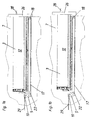
- Fig. 1a can be seen a designed as a drawer movable furniture part 3 in plan view on one of its side surfaces 12. It can be seen that the drawer with a handle 28 is executed.
- the movable furniture part 3 is linearly movable in an inventive Mounted arrangement 7, wherein the power transmission from the drive unit 5 via a Transmission 22 on a toothed belt 17, which runs over rollers 18, takes place. Also visible the drive unit controller 10.
- the power supply of the electrical components takes place via a conductive connection 29.
- the movable furniture part 3 in the to recognize closed end position, in which the front panel 26 of the movable furniture part 3 rests directly on the front of the arrangement 7 according to the invention. Not shown the Switzerlandübung the handle member 28 by a user, not shown, whereby the movable furniture part 3 merges into the tripped state shown in FIG. 1b.
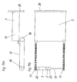
- Fig. 2a again shows the arrangement shown in Figs. 1a and 1b, wherein the movable furniture part 3 has now been transferred to the open end position.
- Fig. 2a again shows the arrangement shown in Figs. 1a and 1b, wherein the movable furniture part 3 has now been transferred to the open end position.
- Fig. 2a again shows the arrangement shown in Figs. 1a and 1b, wherein the movable furniture part 3 has now been transferred to the open end position.
- the two side frames 14, on which the movable furniture part 3 is mounted To recognize is one of the two side frames 14, on which the movable furniture part 3 is mounted.
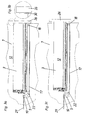
- Figs. 3a, 3b and 3c is an inventive arrangement in touch-latch design shown. It can be seen in Fig. 3a and in detail in Fig. 3b, that in such a Variant also in the closed end position of the movable furniture part 3, a gap 30th between the front of the inventive arrangement and the front panel 26 of the movable furniture part 3 is provided. This allows the opening of the movable Furniture part 3 on a known in such embodiments prior art analogous way, so it will not be discussed further here.
- a support by the drive unit 5 only after release of the movable furniture part 3, i. for example, in the in Fig. 3c shown state. This corresponds to the basic idea that the user to notice as little as possible of the support provided by the drive unit. It But also an immediate support, at least in the pressing on the Be provided front panel subsequent pull-out.
- FIG. 4 a shows a further exemplary embodiment of an arrangement according to the invention, wherein the actuator 11 of an initialization device included in the drive unit 6 can be seen.
- Fig. 4b can be seen in detail that in the closed end position the movable furniture part 3, a distance between the back of the movable furniture part 3 and the actuating element 11 is provided, so that the actuation of the actuating element 11 is carried out without contact by the movable furniture part 3. This is for example in an executed as an inductive sensor actuator 11 possible.
- Fig. 4c shows the movable furniture part 3 of FIGS. 4a and 4b in the tripped state.
- Fig. 5a shows a perspective view of one of the two for lateral mounting on the Inside a device according to the invention provided frame 14, wherein the two arranged on the frame rollers 18, the corresponding teeth for the over the rollers 18 have running toothed belt 17, can be seen.
- Fig. 5b shows in detail the Drive unit 5 with the drive unit controller 10, which in this embodiment via the partially integrated into the drive unit 5 gear 22 one of the rollers 18 and thus the toothed belt 17 drives.
- the movable was Furniture part 3 is not shown.
- Fig. 6 shows a further embodiment in which both side frames 14, 15 can be seen, wherein the drive unit 5 and that of this included gear 22 in the area between the frames on the rear wall, not shown the inventive arrangement is attached. For reasons of clarity was the attached to the frames 14, 15 movable furniture part 3 is not shown.
- FIGS. 7a and 7b now show an exemplary embodiment in which the connecting shaft 19 closes can be seen about the drive unit 5 with the rollers 18 of the two frames 15 in Connection stands.
- Fig. 7b can be seen in detail that the exercise of force in this Embodiment via an intermediate gear 22 takes place.
- Fig. 8a shows the arrangement of Figs. 7a and 7b in a different angle, so that the connection for power application of the drive unit 5 via the connecting shaft 19 a roller 18 of the drive unit 5 further away from the frame 15 can be seen.
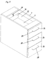
- Fig. 9 shows the perspective view of an embodiment of the invention Arrangement 7, the three movable furniture parts 3 with front panels 26 and handle elements 28th having. To recognize is partially the uppermost mounted movable furniture part 3, of which in particular, a side wall 12 and the rear wall 16. Sectionally recognizes one a part of the conductive connection 29.
- FIG. 10 shows analogous to FIG. 9 shows a variant of the arrangement according to the invention, in which a Touch-latch release is provided. Accordingly, no handle elements to the Front panels 26 are provided.
- Fig. 11a shows again the inventive arrangement of Fig. 10, wherein the uppermost stored movable furniture part 3 was brought into the open end position. It can be seen on the inside of the arrangement 7 according to the invention mounted on the side wall Frame 14, which consists of two parts and whose upper part is designed to be movable, while the lower part is attached to a side wall of the arrangement 7 according to the invention is.
- the detailed view 11b shows the drive unit 5 with the drive unit controller 10 as well the gear 22, the roller 18, the toothed belt 17 and a part of the power supply 29th
- Fig. 12a shows a prior art rotatably mounted disc 23 from Conductive material that is part of a magnetic encoder, not shown, wherein the disc 23 rotatable about a shaft, not shown, with the drive unit. 5 connected is.
- Inductive sensors 27 which can be seen directly above one of the two surfaces of the disc 23 are arranged.
- Two-channel decoder can span the width of each pulse between the two channels the rotational speed and the phase of the individual pulses, the direction of rotation of the Disk 23 and thus the associated with her drive unit 5 are determined and so be deduced to the linear movement of the movable furniture part 3.
- this registers the control device 1 by the of the position measuring device 4, of the the disk 23 and the sensors 27 in this embodiment represent a part, outgoing electrical signals and gives the drive unit 5 via a intermediate drive unit controller 10 command to accelerate the movable furniture part 3 in the direction intended by the user.
- Fig. 12b shows a perspective view of the two components 23 and 27 of FIG. 12a.
- FIG. 12d shows Elements of a position measuring device 4 of a further embodiment, which in present case is designed as an optical encoder and here, of course, at the same time Acceleration measuring device 2 represents.
- a position measuring device 4 of a further embodiment which in present case is designed as an optical encoder and here, of course, at the same time Acceleration measuring device 2 represents.
- Evident are light-emitting elements 25, whose light falls over a shutter 31 on light detecting elements 24, if not is interrupted by the intermediate rotating disk 23.
- the details can be found in the relevant specialist literature.
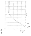
- FIGS. 13a, 13b and 13c show, with the aid of travel-time diagrams, a typical actuation process in the course of which the movable furniture part 3 moves from its closed end position into an intermediate position in which it temporarily comes to rest and after renewed actuation the user is moved to the open end position or, alternatively, back to the closed end position.
- a total path S of approximately 0.43 m between the closed and the open end position.
- the closed end position corresponds to the ordinate origin zero in the path-time diagrams.
- the closed end position corresponds to a position of the movable furniture part 3, in which a gap 30 remains between its front panel 31 and the front side of the arrangement according to the invention.
- FIG. 13b shows a possible course in which the user after a certain time again train on the located in the intermediate position movable furniture part 3 exerts, whereby the control unit 1 via the drive unit controller 10 of the drive unit 5 the command for uniform acceleration of the movable furniture part 3 in Direction of the train acceleration granted. It can therefore be seen in Fig.
- the partial path S 3 is a factory-set braking distance, which ensures a safe deceleration of the movable furniture part 3 during the transition to the open end position.
- this presents itself as a friction effect which is amplified in the area S 3.
- FIG. 13 c shows a likewise possible progression shape in which the user accelerates the movable furniture part 3 located in an intermediate position in the direction of the closed end position by pressure.
- the immediate onset supporting effect of the drive unit 5 which is reflected in the uniformly accelerated movement of the movable furniture part 3 over the section S 2 in the path-time diagram.
- a closed end position upstream protection path S 3 in which the drive unit 5 causes a uniformly accelerated deceleration movement of the movable furniture part 3, in order to transfer them safely and without unnecessary noise in the closed end position.
- the partial paths S 1 , S 2 , S 3 of the entire path S between the closed and the open end positions shown in FIGS. 13 a, 13 b, 13 c are usually preset at the factory. This corresponds to the idea that the user does not want to be burdened with technical details.
- a technically more dedicated user sets the partial routes S 1 , S 2 , S 3 or the time interval t o , via which an acceleration takes place, within certain limits (ie taking into account safety aspects).
- Fig. 14 was shown schematically, in which way the individual components of inventive arrangement exchange information with each other.
- the control device 1, a drive unit controller 10 and a Istwertbeticss worn 8 includes.
- the position measuring device 4 can signals the actual value calculation device 8 pass and has even the possibility of signals from receive the initialization device 6, which in turn via actuators 20, 11, 9 is triggered.
- the drive unit controller 10 receives signals from the Acceleration measuring device 2 and the actual value calculating device 8.
- the schematic logical representation of the information flow between the system elements does not necessarily correspond to the physical arrangement of the same. For example All system elements can save space in an integrated design physically arranged in the arrangement 7 according to the invention.
- FIGS. 15a and 15b show a schematic side view and top view, respectively the bottom surface of the movable furniture part 3 a conceivable arrangement of the system units shown.
- a side surface 13 of the movable Furniture part 3 with a front panel 26, in this embodiment, the inventive Arrangement 7 is designed as a touch-latch construction.
- the movable furniture part 3 is in connection with a belt 17, the two rollers 18 in turn in Connection with a drive unit 5 is.
- the power transmission takes place in this Embodiment on both sides by means of a connecting shaft 19.
- the power transmission of the drive unit 5 takes place in this embodiment via two gear 22, which are arranged on the left and right of the drive unit, and in conjunction with the Connecting shaft 19 are.
- Acceleration measuring device 2 between a transmission 22 and the drive unit 5 is arranged.
- the remaining system components such as the position measuring device 4, the actual value calculation device 8, the drive unit controller 10 and the Initialization device 6 and its possible actuators were in Figs. 15a and 15b are not shown. They can be explained as above in a the average Professional familiar manner be integrated in the illustrated system components and so on perform their functions.
Landscapes
- Power-Operated Mechanisms For Wings (AREA)
- Drawers Of Furniture (AREA)
Abstract
Description
Die vorliegende Erfindung betrifft eine Anordnung mit wenigstens einem bewegbaren Möbelteil, insbesondere mit einer Schublade, oder dergleichen, mit wenigstens einer Antriebseinheit und mit wenigstens einer Regeleinrichtung zur Regelung der wenigstens einen Antriebseinheit.The present invention relates to an arrangement with at least one movable Furniture part, in particular with a drawer, or the like, with at least one Drive unit and with at least one control device for controlling the at least a drive unit.
Derartige Anordnungen sind grundsätzlich bereits bekannt. Die US 5,158,347 beschreibt
beispielsweise ein Büromöbel, bei dem die Schubladen nach Eingabe eines Identifizierungscodes
motorisch über einen ersten Bereich des gesamten Öffnungsweges bewegt werden.
Die EP 0 957 225 beschreibt eine Öffnungsvorrichtung für ein Verschlußelement, beispielsweise
eine Schublade, die über einen Kondensator, der sich bei Berührung durch den
Benutzer elektrisch entlädt, ausgelöst wird. Auch hier erfolgt nur eine teilweise Herausbewegung
der Schublade aus dem Möbelkorpus. Die deutsche Patentschrift DE 10 17 351
beschreibt eine Einrichtung zum Ausziehen oder Einschieben von Schubladen in Möbelstücken,
die durch korpusseitig angeordnete Drucktasten auslösbar ist. Dabei ist mit Hilfe der
Drucktasten jede mögliche Positionierung der Schublade entlang des gesamten Öffnungsweges
möglich. Problematisch ist in diesem Zusammenhang, dass derartige Öffnungshilfen
stets über eigens dafür vorgesehene Betätigungselemente auszulösen sind, was von vielen
Benutzern als unangenehm empfunden wird. Besonders für Menschen, die der Technik im
allgemeinen skeptisch gegenüberstehen, wäre es vorteilhaft, angetriebene bewegbare
Möbelteile auf alt hergebrachte Art durch Zug- oder Druckausübung auf die Schublade
bedienen zu können.Such arrangements are already known in principle. US 5,158,347 describes
For example, an office furniture in which the drawers after entering an identification code
be moved by a motor over a first area of the entire opening path.
Aufgabe der vorliegenden Erfindung ist es, eine gattungsgemäße Anordnung zu schaffen, die ein intuitives Bedienen eines durch eine Antriebseinheit angetriebenen bewegbaren Möbelteiles ermöglicht.The object of the present invention is to provide a generic arrangement, an intuitive operation of a driven by a drive unit movable Furniture part allows.
Dies wird erfindungsgemäß dadurch erreicht, dass die Anordnung wenigstens eine, vorzugsweise analoge, Beschleunigungsmesseinrichtung aufweist, wobei die wenigstens eine Beschleunigungsmesseinrichtung ein für durch von außen an das wenigstens eine bewegbare Möbelteil angelegte Kräfte verursachte Beschleunigungen charakteristisches Beschleunigungssignal erzeugt, welches der wenigstens einen Regeleinrichtung zuführbar ist.This is inventively achieved in that the arrangement at least one, preferably has analog, acceleration measuring device, wherein the at least one Acceleration measuring device for a through from the outside to the at least one movable Furniture part applied forces caused accelerations characteristic acceleration signal generated, which is the at least one control device supplied.
Technisch vorteilhaft ist daran, dass bei der erfindungsgemäßen Anordnung keinerlei Betätigungselemente zur Auslösung der Antriebseinheit für die bewegbaren Möbelteile mehr vorgesehen sind. Wirtschaftlich vorteilhaft ist daran, dass eine größere Akzeptanz der erfindungsgemäßen Anordnung am Markt zu erwarten ist.Technically advantageous is that in the inventive arrangement no Actuators for triggering the drive unit for the movable furniture parts more are provided. Economically advantageous is that a greater acceptance of the inventive arrangement is expected on the market.
Es ist nicht von Bedeutung ob die Beschleunigung direkt gemessen oder aus anderen gemessenen Größen errechnet wird. In diesem Sinne stellt auch eine Einrichtung zur Positionsbestimmung des bewegbaren Möbelteils zusammen mit einer Uhr eine Beschleunigungsmesseinrichtung dar. In diesem Fall kann aus der in einer gewissen Zeitspanne zurückgelegten Strecke die Geschwindigkeit und aus der Änderung der Geschwindigkeit die Beschleunigung bestimmt werden.It does not matter if the acceleration is measured directly or from another measured quantities is calculated. In this sense, also constitutes an institution Positioning of the movable furniture part together with a clock one In this case, from the in a certain Time span traveled the speed and change of the distance Speed the acceleration can be determined.
Erfindungsgemäß genügt aber bereits das Erkennen der Tatsache, dass eine Beschleunigung des bewegbaren Möbelteils erfolgt ist, unabhängig vom Betrag oder der Richtung der Beschleunigung.However, according to the invention, it is sufficient to recognize the fact that a Acceleration of the movable furniture part is done, regardless of the amount or the Direction of acceleration.
Günstigerweise ist in einer Ausführungsform der Erfindung vorgesehen, dass die wenigstens eine Antriebseinheit einen elektrischen Motor umfaßt. Derartige elektrische Motoren sind in Kleinstbauweise kommerziell erhältlich und garantieren bei geringem Strombedarf einen problemlosen Betrieb.Conveniently, in one embodiment of the invention, it is provided that the at least a drive unit comprises an electric motor. Such electric motors are in Miniature construction commercially available and guarantee a low power consumption trouble-free operation.
Eine besonders vorteilhafte Ausführungsform der Erfindung ergibt sich dadurch, dass das Beschleunigungssignal Informationen über den Betrag und/oder über die Richtung, vorzugsweise über die Richtungskomponente parallel zur Auszugsrichtung des bewegbaren Möbelteils der durch von außen an das bewegbare Möbelteil angelegten Kräfte verursachten Beschleunigung beinhaltet. Damit kann die Beschleunigungsmesseinrichtung der Regeleinrichtung Informationen darüber zur Verfügung stellen, in welche Richtung die Betätigung der Schublade erfolgen soll. Erhält die Regeleinrichtung beispielsweise von der Beschleunigungsmesseinrichtung das Signal einer vorliegenden Zugbeschleunigung, kann sie der Antriebseinheit sofort einen Steuerbefehl zum Bewegen des bewegbaren Möbelteils in Richtung der gemessenen Zugbeschleunigung zusenden. Dabei spielt es an und für sich keine Rolle, in welchem Öffnungszustand sich die Schublade zum Zeitpunkt der externen Betätigung befindet. Günstigerweise ist aber vorgesehen, dass in einem gewissen Bereich vor der geöffneten sowie der geschlossenen Endlage des bewegbaren Möbelteils keine angetriebene Bewegung des Möbelteils mehr erfolgt, um eine Beschädigung des Möbelteils bzw. der erfindungsgemäßen Anordnung zu verhindern. Dazu ist es vorteilhaft, dass die Anordnung mindestens eine Positionsmesseinrichtung aufweist, welche ein für den Öffnungszustand des bewegbaren Möbelteils charakteristisches und der Regeleinrichtung zuführbares Positionssignal erzeugt. So kann die Regeleinrichtung zu jeder Zeit erkennen, ob sich das bewegbare Möbelteil in der Nähe einer der Endlagen befindet.A particularly advantageous embodiment of the invention results from the fact that the Acceleration signal information about the amount and / or direction, preferably via the direction component parallel to the extension direction of the movable Furniture part caused by externally applied to the movable furniture part forces Acceleration includes. Thus, the acceleration measuring device of the Control device provide information on which direction the Operation of the drawer should take place. Receives the control device, for example, from the Acceleration measuring device, the signal of a present Zugbeschleunigung can the drive unit immediately a control command to move the movable furniture part send in the direction of measured train acceleration. It plays in and of itself No matter in which opening state the drawer at the time of external Actuation is located. Conveniently, it is provided that in a certain range in front of the open as well as the closed end position of the movable furniture part no driven movement of the furniture part is done more to damage the furniture part or to prevent the inventive arrangement. For this it is advantageous that the Arrangement comprises at least one position measuring device, which is one for the Opening state of the movable furniture part characteristic and the control device generates deliverable position signal. So the controller can recognize at any time whether the movable furniture part is near one of the end positions.
Vorteilhafterweise beinhaltet das Beschleunigungssignal, das von der Beschleunigungsmesseinrichtung an die Regeleinrichtung ergeht, auch Informationen über den Betrag der vom Benutzer ausgeübten Beschleunigung des bewegbaren Möbelteils. Aus einem großen Betrag der Beschleunigung kann beispielsweise geschlossen werden, dass ein rasches Öffnen bzw. Schließen gewünscht wird, wodurch die Regeleinheit die Antriebseinheit der Situation entsprechend betätigen kann.Advantageously, the acceleration signal included by the Acceleration measuring device goes to the control device, also information about the amount of user-applied acceleration of the movable furniture part. Out For example, a large amount of acceleration can be inferred that a rapid opening or closing is desired, whereby the control unit the Drive unit of the situation can operate accordingly.
Eine vorteilhafte Ausführungsform der Erfindung ergibt sich dadurch, dass die Antriebseinheit das bewegbare Möbelteil über eine vorgegebene Zeitspanne annähernd gleichmäßig beschleunigt. Dadurch, dass die Beschleunigung des bewegbaren Möbelteils nur über eine vorgegebene Zeitspanne erfolgt, wird für den Benutzer die Illusion eines nicht angetriebenen Möbelteils aufrecht erhalten. Nach Ablauf der Zeitspanne wird das bewegbare Möbelteil durch die systembedingte Reibung abgebremst, ganz so, als ob keine Antriebseinheit vorhanden wäre. Es könnte allerdings auch vorgesehen sein, dass nach der Beschleunigungszeitspanne eine geringere Beschleunigung zum Ausgleich der durch die Reibung verursachten Bremsung aufrecht erhalten wird. Dadurch wird der Eindruck eines nicht angetriebenen Möbelteils aufrecht erhalten, das beispielsweise besonders reibungsarm gelagert ist. Alternativ oder ergänzend kann auch vorgesehen sein, dass die Antriebseinheit das bewegbare Möbelteil nur über einen vorgebbaren bzw. vorgegebenen Teilweg, dessen Länge kleiner ist als die Länge des Gesamtweges zwischen der geschlossenen und der geöffneten Endlage des bewegbaren Möbelteils, beschleunigt. Dadurch, dass die Antriebseinheit nicht über den gesamten Öffnungsweg aktiv ist, wird die angestrebte Unsichtbarkeit der Technik beibehalten.An advantageous embodiment of the invention results from the fact that the Drive unit approximately the movable furniture part over a predetermined period of time evenly accelerated. Thereby, that the acceleration of the movable furniture part takes place only for a predetermined period of time, the illusion of one does not for the user maintained driven furniture part. After the expiration of the period of time becomes the movable Furniture part braked by the systemic friction, just as if no Drive unit would be available. However, it could also be provided that after the Acceleration period a lower acceleration to compensate for by the Friction caused braking is maintained. This will give the impression of a maintained non-powered furniture part, for example, particularly low friction is stored. Alternatively or additionally, it can also be provided that the drive unit the movable furniture part only via a predetermined or predetermined partial path, the Length is less than the length of the total path between the closed and the opened end position of the movable furniture part, accelerated. Because of that Drive unit is not active over the entire opening path is the desired Retain invisibility of the technique.
Es kann auch vorgesehen sein, dass die Bewegung des bewegbaren Möbelteils durch die Antriebseinheit unabhängig vom Betrag der Zug- oder Druckbeschleunigung ist. Dadurch entscheidet allein der Benutzer durch den Betrag seiner Kraftaufwendung, wie schnell die Bewegung des bewegbaren Möbelteils erfolgen soll, wobei von der Antriebseinheit immer dieselbe unterstützende Beschleunigung erfolgt.It can also be provided that the movement of the movable furniture part through the Drive unit is independent of the amount of tensile or compressive acceleration. Thereby Only the user decides by the amount of his effort, how fast the Movement of the movable furniture part should be carried out, being always by the drive unit the same supporting acceleration occurs.
Eine besonders vorteilhafte Ausführungsform der Erfindung ergibt sich dadurch, dass die Regeleinrichtung eine Istwertberechnungseinrichtung aufweist, welche aus dem von der Positionsmesseinrichtung erzeugten Positionssignal, die momentane Istposition und/oder die momentane Istgeschwindigkeit des bewegbaren Möbelteils berechnet. Durch die Kenntnis der momentanen Position und Geschwindigkeit des bewegbaren Möbelteils ist es möglich, auf definierten Teilstrecken, beispielsweise in der Nähe der Endlagen des bewegbaren Möbelteils, durch die Antriebseinheit eine Beschleunigung derart vorzunehmen, dass das bewegbare Möbelteil in der jeweiligen Endlage zum Stillstand kommt.A particularly advantageous embodiment of the invention results from the fact that the Control device has an actual value calculation device, which from the of Position measuring device generated position signal, the current actual position and / or the current actual speed of the movable furniture part calculated. By the It is aware of the current position and speed of the movable furniture part possible, on defined sections, for example in the vicinity of the end positions of movable furniture part to make by the drive unit acceleration such that the movable furniture part comes to a standstill in the respective end position.
Bei einer weiteren vorteilhaften Ausführungsform der Erfindung ist vorgesehen, dass die Anordnung wenigstens eine Initialisierungsvorrichtung umfaßt, welche ein jeweils für bestimmte vorgegebene Positionen des bewegbaren Möbelteils charakteristisches, wenigstens der Positionsmesseinrichtung zuführbares, Signal erzeugt. Ist die erfindungsgemäße Anordnung nicht mit teuren dauerhaften elektronischen Speicherelementen ausgerüstet, muß beispielsweise nach der Trennung der erfindungsgemäßen Anordnung von der Spannungsquelle die Position des bewegbaren Möbelteils in bezug auf die erfindungsgemäße Anordnung festgestellt werden. Da die erfindungsgemäße Anordnung außerdem in verschieden dimensionierter Form auf dem Markt erhältlich sein kann, ist es wenigstens bei der erstmaligen Inbetriebnahme notwendig, die Länge des Gesamtweges zwischen der geschlossenen und der geöffneten Endlage des bewegbaren Möbelteils sowie die Positionen des bewegbaren Möbelteils in der geschlossenen und der geöffneten Endlage festzustellen. Dies kann beispielsweise dadurch erfolgen, dass der Benutzer die Initialisierungsvorrichtung über ein von außerhalb der Anordnung leicht zugängliches Betätigungselement, beispielsweise einen Taster, auslöst. Bei einem derartigen Initialisierungsvorgang kann beispielsweise vorgesehen sein, dass der Benutzer das bewegbare Möbelteil in die geschlossene Endlage bewegt, dort das Betätigungselement betätigt und sodann das bewegbare Möbelteil in die geöffnete Endlage bewegt und wiederum das Betätigungselement betätigt. Dadurch stehen der Regeleinrichtung die benötigten Informationen über die Gesamtlänge der Bewegung des bewegbaren Möbelteils sowie über die Position des bewegbaren Möbelteils in den speziellen Lagen zur Verfügung.In a further advantageous embodiment of the invention it is provided that the Arrangement comprises at least one initialization device, each one for certain predetermined positions of the movable furniture part characteristic, generated at least the position measuring device, signal generated. Is the inventive arrangement not with expensive permanent electronic storage elements equipped, for example, after the separation of the invention Arrangement of the voltage source, the position of the movable furniture part with respect to the arrangement according to the invention can be determined. As the inventive arrangement Moreover, it can be available in various dimensions on the market, it is at least at the first commissioning necessary, the length of the total route between the closed and the open end position of the movable furniture part as well the positions of the movable furniture part in the closed and the open end position determine. This can be done, for example, that the user the Initialization device via an easily accessible from outside the arrangement Actuating element, such as a button, triggers. In such a Initialization process can be provided, for example, that the user moved movable furniture part in the closed end position, there the actuator actuated and then moves the movable furniture part in the open end position and in turn actuates the actuator. As a result, the control device are the required information about the total length of movement of the movable furniture part as well as the position of the movable furniture part in the special layers available.
Alternativ dazu oder ergänzend wäre auch eine Initialisierung durch Kollisionserkennung möglich. Dabei würde das bewegbare Möbelteil langsam in Richtung einer der beiden Endlagen fahren und bei deren Erreichung durch die detektierte Kollision automatisch die Initialisierungsvorrichtung auslösen. Beispielsweise könnte das bewegbare Möbelteil durch die Antriebseinheit zuerst in Richtung der geschlossenen Endlage bewegt und bei Kollision der Frontblende mit der Vorderseite der Anordnung automatisch die Position Null durch die Initialisierungsvorrichtung festgestellt werden. Danach könnte das bewegbare Möbelteil durch die Antriebseinheit in Richtung der geöffneten Endlage bewegt und bei Kollision automatisch diese Position durch die Initialisierungsvorrichtung festgelegt werden. Die Kollision selbst könnte z.B. durch einen plötzlichen Anstieg des der Antriebseinheit zugeführten Stromes detektiert werden, wobei der Anstieg auf die zwischen bewegbarem Möbelteil und Anordnung auftretenden Kräfte zurückzuführen ist, die die Antriebseinheit zu überwinden versucht. Bei Überschreitung einer bestimmten Stromstärke würde es natürlich zur Abschaltung der Antriebseinheit kommen um eine Beschädigung zu verhindern. Es wäre auch möglich, die Initialisierungsvorrichtung auszulösen, wenn der Betrag der Geschwindigkeit des bewegbaren Möbelteils über einen vorgegebenen Zeitraum kleiner gleich einem vorgegebenen Grenzwert, vorzugsweise Null, ist.Alternatively or in addition to an initialization by collision detection would be possible. The movable furniture would slowly move towards one of the two Driving end positions and when they reach the detected collision automatically Trigger the initialization device. For example, the movable furniture part could through the drive unit is first moved in the direction of the closed end position and in collision the front panel with the front of the arrangement automatically zero position through the Initialization device are detected. After that, the movable furniture part could moved by the drive unit in the direction of the open end position and in collision automatically this position be determined by the initialization device. The collision itself could e.g. by a sudden increase in the drive unit supplied current, wherein the increase on the movable between Furniture part and arrangement occurring forces is due to the drive unit to tried to overcome. When exceeding a certain amperage it would be natural to shut down the drive unit to prevent damage. It would be also possible to trigger the initialization device when the amount of Speed of the movable furniture part smaller over a given period of time is equal to a predetermined limit, preferably zero.
Bei einer Touch-Latch-Ausführung wäre die von der Initialisierungsvorrichtung festgelegte geschlossene Endlage natürlich nicht die Lage des bewegbaren Möbelteils bei Kollision, sondern eine um ein vorgegebene Strecke weiter außen liegende Lage. Dadurch würde der für die Touch-Latch-Auslösung benötigte Spalt zwischen der Vorderseite der Anordnung und der Frontblende des bewegbaren Möbelteils in der geschlossenen Endlage sichergestellt werden.In a touch-latch embodiment, the one specified by the initialization device would be closed end position of course not the position of the movable furniture part in collision, but a location further out by a predetermined distance. This would be the required for the touch-latch release gap between the front of the arrangement and the front panel of the movable furniture part in the closed end position ensured become.
Bei einer weiteren vorteilhaften Ausführungsform der Erfindung ist vorgesehen, dass die Initialisierungsvorrichtung über ein innerhalb der Anordnung angeordnetes, vom bewegbaren Möbelteil betätigbares Betätigungselement auslösbar ist. Dadurch wird dem Benutzer das Betätigen eines speziellen Betätigungselementes erspart. Ein derartiges innerhalb der Anordnung angeordnetes Betätigungselement kann beispielsweise als Endschalter zur Bestimmung der geschlossenen Endlage des bewegbaren Möbelteils ausgebildet sein. Beispielhaft kann vorgesehen sein, dass dieser Endschalter als Druckschalter ausgebildet ist. Durch das Einschieben des bewegbaren Möbelteils entweder über die Antriebseinheit oder durch den Benutzer wird der Endschalter auf den letzten Millimetern des Einschubweges durch das bewegbare Möbelteil betätigt. Dadurch wird die geschlossene Endlage des bewegbaren Möbelteils in der erfindungsgemäßen Anordnung festgelegt. Es kann auch vorgesehen sein, dass der Endschalter bzw. das Betätigungselement im allgemeinen als induktiver oder kapazitiver Sensor ausgebildet ist, sodass die Registrierung der jeweiligen Endlagen des bewegbaren Möbelteils berührungsfrei erfolgen kann. Auch andere dem Fachmann geläufige Arten von Sensoren können vorgesehen sein.In a further advantageous embodiment of the invention it is provided that the Initialization device via a disposed within the array, the movable Furniture part operable actuator is triggered. This will give the user the Actuation of a special actuator saves. Such within the Arrangement arranged actuator can, for example, as a limit switch for Determining the closed end position of the movable furniture part to be formed. By way of example, it can be provided that this limit switch is designed as a pressure switch is. By inserting the movable furniture part either via the drive unit or by the user, the limit switch on the last millimeters of the Insertion path operated by the movable furniture part. This will make the closed End position of the movable furniture part set in the inventive arrangement. It can also be provided that the limit switch or the actuating element in generally designed as an inductive or capacitive sensor, so that the registration the respective end positions of the movable furniture part can be done without contact. Also Other types of sensors known to those skilled in the art may be provided.
Denkbar ist auch, dass die Initialisierungsvorrichtung durch die Herstellung einer leitenden Verbindung der Anordnung mit einer Spannungsquelle über ein Auslöseelement auslösbar ist. Dadurch erfolgt eine Initialisierung automatisch bei der erstmaligen Inbetriebnahme bzw. bei der Wiederherstellung der Spannungsversorgung nach einem Stromausfall.It is also conceivable that the initialization device by the production of a conductive Connection of the arrangement with a voltage source via a trigger element triggered is. This will automatically initialize the first time Commissioning or when restoring the power supply to one Power failure.
Selbstverständlich kann auch vorgesehen sein, zwei oder mehrere Ausführungen der obengenannten Betätigungsweisen der Initialisierungsvorrichtung in einer erfindungsgemäßen Anordnung zu kombinieren. Die Auslösung der Initialisierungsvorrichtung kann natürlich auch durch Handauszug erfolgen. Dabei wird das bewegbare Möbelteil manuell durch einen Benutzer beispielsweise aus der geschlossenen Endlage in die voll geöffnete Endlage bewegt.Of course, can also be provided, two or more versions of above-mentioned operations of the initialization device in an inventive Combine arrangement. The triggering of the initialization device can Of course, also done by hand extract. In this case, the movable furniture part is manually by a user, for example, from the closed end position in the fully open End position moves.
Bei einer weiteren vorteilhaften Ausführungsform der Erfindung ist vorgesehen, dass das bewegbare Möbelteil bewegbar an seitlich innerhalb der Anordnung angeordneten Zargen gelagert ist. Derartige Zargen, die für sich genommen Stand der Technik sind, erlauben die reibungsarme und sichere Lagerung des bewegbaren Möbelteils in der erfindungsgemäßen Anordnung.In a further advantageous embodiment of the invention it is provided that the movable Furniture part movably mounted on laterally arranged within the arrangement of frames is. Such frames, which are state of the art in their own right, allow the low friction and safe storage of the movable furniture part in the invention Arrangement.
Bei einer weiteren vorteilhaften Ausführungsform der Erfindung ist vorgesehen, dass die Antriebseinheit an einer Zarge angebracht ist. Dadurch kann beispielsweise für jedes bewegbare Möbelteil eine eigene Antriebseinheit zur Verfügung gestellt werden. Es kann auch möglich sein, von vornherein Zargen, an denen Antriebseinheiten befestigt sind, in einer erfindungsgemäßen Anordnung anzubringen.In a further advantageous embodiment of the invention it is provided that the Drive unit is attached to a frame. This can, for example, for each movable furniture part is provided its own drive unit. It can also be possible from the outset frames on which drive units are mounted in to install an arrangement according to the invention.
Bei einer weiteren vorteilhaften Ausführungsform der Erfindung ist vorgesehen, dass die Antriebseinheit an der Rückwand des bewegbaren Möbelteils gegenüberliegenden Innenfläche der Anordnung, vorzugsweise in annähernd gleichem Abstand zu den beiden Seitenwänden der Anordnung, angebracht ist. Dies gestattet bei mittiger Anordnung der Antriebseinheit eine weitgehend verkantungsfreie Beschleunigung des bewegbaren Möbelteils.In a further advantageous embodiment of the invention it is provided that the Drive unit on the rear wall of the movable furniture part opposite inner surface the arrangement, preferably at approximately the same distance from the two side walls the arrangement is attached. This allows for central arrangement of the drive unit a largely tilt-free acceleration of the movable furniture part.
Bei einer weiteren vorteilhaften Ausführungsform der Erfindung ist vorgesehen, dass die Antriebseinheit in ständiger Verbindung mit dem bewegbaren Möbelteil steht. Dadurch ist die Beschleunigung des bewegbaren Möbelteils durch die Antriebseinheit unabhängig von der momentanen Lage des bewegbaren Möbelteils in bezug auf die erfindungsgemäße Anordnung möglich. Dafür bietet sich beispielsweise an, dass die Antriebseinheit über wenigstens ein Seil oder einen Riemen, vorzugsweise Zahnriemen, oder über ein in eine Zahnstange eingreifendes Zahnrad in ständiger Verbindung mit dem bewegbaren Möbelteil steht. Die Verwendung eines Zahnriemens garantiert dabei die schlupffreie Verbindung zwischen dem bewegbaren Möbelteil und der Antriebseinheit. Die Kraftausübung kann beispielsweise dadurch erfolgen, dass der Riemen über wenigstens zwei Rollen läuft, die an einer seitlichen Zarge angeordnet sind. Natürlich können auch beide seitlichen Zargen mit wenigstens zwei Rollen ausgeführt sein, über die jeweils ein Riemen zur Kraftübertragung geführt wird. Natürlich wäre auch die Verwendung eines Seils ohne Schlupf möglich, wenn auf der angetriebenen Rolle beide Seilenden fixiert sind und somit gleichzeitig das eine Seilende abgewickelt und das andere Seilende aufgewickelt wird.In a further advantageous embodiment of the invention it is provided that the Drive unit is in constant communication with the movable furniture part. This is the result Acceleration of the movable furniture part by the drive unit regardless of the current position of the movable furniture part with respect to the inventive Arrangement possible. For example, suggests that the drive unit via at least one rope or a belt, preferably a toothed belt, or one in one Rack-engaging gear in constant communication with the movable furniture part stands. The use of a toothed belt guarantees the slip-free connection between the movable furniture part and the drive unit. The exercise of power can For example, take place in that the belt over at least two rollers running on the a side frame are arranged. Of course you can also use both side frames be carried out at least two roles, each having a belt for power transmission to be led. Of course, the use of a rope without slippage would be possible if are fixed on the driven roller both ends of the rope and thus at the same time the one Rope end unwound and the other end of the rope is wound up.
Ab einer gewissen Breite des bewegbaren Möbelteils ist es vorteilhaft, dass wenigstens zwei an unterschiedlichen Zargen angeordnete Rollen über eine Verbindungswelle miteinander in - vorzugsweise starrer - Verbindung stehen und so durch die Antriebseinheit bewegbar sind.From a certain width of the movable furniture part, it is advantageous that at least two arranged on different frames rollers over a connecting shaft with each other in - Preferably rigid - connection and are so moved by the drive unit.
Eine weitere vorteilhafte Ausführungsform der Erfindung ergibt sich dadurch, dass wenigstens eine Rolle an wenigstens einer Zarge durch die Antriebseinheit antreibbar ist. Dies gestattet eine verlustärmere Kraftübertragung als bei der Zwischenschaltung von Übertragungseinrichtungen zwischen der Antriebseinheit und dem bewegbaren Möbelteil erzielbar wäre.A further advantageous embodiment of the invention results from the fact that at least one roller is drivable on at least one frame by the drive unit. This allows a lower-loss power transmission than in the interposition of Transmission devices between the drive unit and the movable furniture part would be achievable.
Um eine günstigere Übersetzung der Bewegung der Antriebseinheit auf das bewegbare Möbelteil zu erzielen, kann vorgesehen sein, dass die wenigstens eine Rolle an wenigstens einer Zarge über ein Getriebe durch die Antriebseinheit antreibbar ist. Bei einem breiten bewegbaren Möbelteil bietet es sich wieder an, an beiden Enden der Verbindungswelle Getriebe vorzusehen. Bei sehr breiten bewegbaren Möbelteilen kann auch vorgesehen sein, an beiden Seiten des bewegbaren Möbelteils Antriebseinheiten anzuordnen, die entweder über eigene Regelungseinrichtungen sowie eine Synchronisierungsvorrichtung verfügen oder von einer gemeinsamen Regelungsvorrichtung angesteuert werden.To a cheaper translation of the movement of the drive unit to the movable To achieve furniture part, it can be provided that the at least one roller on at least a frame via a transmission by the drive unit is driven. At a wide movable furniture part, it offers itself again, at both ends of the connecting shaft Provide gear. For very wide movable furniture parts can also be provided To arrange on both sides of the movable furniture part drive units, either have their own control devices and a synchronization device or be driven by a common control device.
Bei einer weiteren vorteilhaften Ausführungsform der Erfindung kann vorgesehen sein, dass die Anordnung einen Resolver zur Messung der Position und/oder der Geschwindigkeit und/oder der Beschleunigung des bewegbaren Möbelteils umfaßt, dessen Signale der Regeleinrichtung zuführbar sind. Derartige Resolver sind kommerziell erhältlich und mechanisch sowie thermisch äußerst robust. Ein derartiger Resolver ist nach dem Drehtransformatorprinzip aufgebaut. Handelsübliche Resolver sind häufig mit integrierter Auswerteschaltung erhältlich, sodass deren Signal direkt der Regeleinrichtung zugeführt werden kann. In a further advantageous embodiment of the invention can be provided that the arrangement comprises a resolver for measuring the position and / or the speed and / or the acceleration of the movable furniture part comprises, the signals of the control device can be fed. Such resolvers are commercially available and mechanical as well as extremely thermally robust. Such a resolver is based on the rotary transformer principle built up. Commercially available resolvers are often with integrated evaluation circuit available, so that their signal can be fed directly to the control device.
Bei einer weiteren vorteilhaften Ausführungsform der Erfindung kann vorgesehen sein, dass die Anordnung einen optischen Encoder zur Messung der Position und/oder der Geschwindigkeit und/oder der Beschleunigung des bewegbaren Möbelteils umfaßt, dessen Signale der Regeleinrichtung zuführbar sind. Derartige optische oder auch magnetische Encoder stellen eine preisgünstige und häufig auch raumsparende Alternative zu den Resolvern dar. Dabei garantieren sie immer noch einen für eine erfindungsgemäße Anordnung zufriedenstellenden Winkelauflösungsbereich, beispielsweise von 64 bis 1024 Impulsen/Umdrehung. Gewisse Nachteile bei optischen und magnetischen Encodern ergeben sich aus deren Empfindlichkeit gegenüber mechanischen Vibrationen, Verschmutzungen und dem Fehlen einer absoluten Winkelinformation zum Einschaltzeitpunkt, sodass derartige Encoder nur inkrementale Positionsbestimmungen vornehmen können.In a further advantageous embodiment of the invention can be provided that the arrangement has an optical encoder for measuring the position and / or the speed and / or the acceleration of the movable furniture part comprises, whose signals can be supplied to the control device. Such optical or also Magnetic encoders provide a low-cost and often space-saving alternative to the resolvers dar. They still guarantee one for an inventive Arrangement satisfactory angular resolution range, for example, from 64 to 1024 Pulses / revolution. Certain disadvantages with optical and magnetic encoders arise from their sensitivity to mechanical vibration, contamination and the absence of absolute angle information at the time of turn-on, so that such encoders can only make incremental position determinations.
Bei einer weiteren vorteilhaften Ausführungsform der Erfindung ist vorgesehen, dass die Antriebseinheit einen bürstenlosen Gleichstrommotor umfaßt und die Messung der Position und/oder der Geschwindigkeit und/oder der Geschwindigkeit und/oder der Beschleunigung des bewegbaren Möbelteils direkt über das Kommutatorsignal erfolgt, wobei die derart gewonnenen Signale der Regeleinrichtung zuführbar sind. Häufig sind derartige bürstenlose Motoren mit Hallsensoren ausgeführt kommerziell erhältlich.In a further advantageous embodiment of the invention it is provided that the Drive unit includes a brushless DC motor and measuring the position and / or the speed and / or the speed and / or the acceleration of the movable furniture part is done directly via the commutator signal, the like obtained signals can be fed to the control device. Frequently, such brushless Motors with Hall sensors running commercially available.
Heutzutage sind bereits elektrische Motoren in Kleinstbauweise erhältlich, bei denen eine elektronische, optische oder magnetische Positionsmesseinrichtung bereits im elektrischen Motor integriert ist, was sowohl Platz als auch Zeit beim Einbau spart.Nowadays electric motors are already available in miniature construction, in which a electronic, optical or magnetic position measuring device already in the electrical Engine is integrated, which saves both space and time during installation.
Die vorliegende Erfindung betrifft weiters ein Verfahren zum Bewegen eines in oder an einer Anordnung gelagerten bewegbaren Möbelteils, insbesondere Schublade, durch eine Antriebseinheit, insbesondere elektrischer Motor, wobei die Anordnung einen Antriebeinheitsregler und eine Positionsmesseinrichtung aufweist, dadurch gekennzeichnet, dass die Positionsmesseinrichtung dem Antriebeinheitsregler Signale zusendet und der Antriebeinheitsregler in Abhängigkeit von diesen Signalen der Antriebseinheit den Befehl zur Beschleunigung des bewegbaren Möbelteils gibt.The present invention further relates to a method for moving a in or on a Arrangement mounted movable furniture part, in particular drawer, by a Drive unit, in particular electric motor, wherein the arrangement has a Drive unit controller and a position measuring device, characterized the position measuring device sends signals to the drive unit controller and the Drive unit controller in response to these signals of the drive unit command to Acceleration of the movable furniture part there.
Die Positionsmesseinrichtung stellt dabei, wie bereits ausgeführt, eine besonders einfache Realisierung der Beschleunigungsmesseinrichtung dar.The position measuring device, as already stated, is a particularly simple one Realization of the acceleration measuring device.
Beispielsweise kann vorgesehen sein, dass die Positionsmesseinrichtung bei einer extern verursachten Änderung des Bewegungszustandes des bewegbaren Möbelteils ein Signal an den Antriebeinheitsregler sendet und dieser der Antriebseinheit den Befehl zur Beschleunigung des bewegbaren Möbelteils gibt. Unter Änderung des Bewegungszustandes ist natürlich - wie in der Physik üblich - sowohl das Anfahren des bewegbaren Möbelteils als auch eine Änderung der Geschwindigkeit eines eine gleichförmige Bewegung ausführenden bewegbaren Möbelteils zu verstehen.For example, it can be provided that the position measuring device in an external caused change in the state of movement of the movable furniture part to a signal sends the drive unit controller and this the drive unit command to Acceleration of the movable furniture part there. Under change of the movement state is of course - as usual in physics - both the start of the movable furniture part as also changing the speed of a uniform motion exporting to understand movable furniture part.
Es kann aber auch vorgesehen sein, dass die Positionsmesseinrichtung nach der Bewegung des bewegbaren Möbelteils über eine vorgebbare bzw. vorgegebene Strecke ein Signal an den Antriebeinheitsregler sendet und dieser der Antriebseinheit den Befehl zur Beschleunigung des bewegbaren Möbelteils gibt. Hierbei handelt es sich also um eine reine Wegmessung. Die Antriebseinheit wird aktiviert, sobald das bewegbare Möbelteil die vorgegebene Strecke zurückgelegt hat. Die Zeit, die es dafür benötigt, spielt keine Rolle.But it can also be provided that the position measuring device after the movement the movable furniture part via a predetermined or predetermined distance to a signal sends the drive unit controller and this the drive unit command to Acceleration of the movable furniture part there. This is a pure one Displacement measurement. The drive unit is activated as soon as the movable furniture part the has traveled the specified distance. The time it takes for this does not matter.
Bei diesem Auslösungsverfahren kann vorteilhafterweise weiters vorgesehen sein, dass die vom bewegbaren Möbelteil zurückzulegende Strecke, nach der die Positionsmesseinrichtung ein Signal an den Antriebeinheitsregler abgibt, je nach Bewegungsrichtung des bewegbaren Möbelteils unterschiedlich einstellbar bzw. eingestellt ist. Beispielsweise könnte als Aktivierungsweg zur Auslösung einer vom Möbelkorpus weg gerichteten Bewegung ein Weg von 1 Millimeter gewählt werden, während die Auslösung einer zum Möbelkorpus hin gerichteten Bewegung nach einem Weg von 10 Millimetern erfolgt.In this triggering method can advantageously be further provided that the From the movable furniture part zurückzulegende route, after the position measuring device sends a signal to the drive unit controller, depending on the direction of movement of the movable Furniture part is different adjustable or set. For example, as Activation way to trigger a movement away from the furniture body a way of 1 millimeter, while triggering one towards the furniture body directed movement takes place after a distance of 10 millimeters.
Weitere Vorteile und Einzelheiten der erfindungsgemäßen Anordnung ergeben sich aus den
nachfolgenden Figuren sowie den dazugehörigen Figurenbeschreibungen. Dabei zeigen:
In Fig. 1a erkennt man ein als Schublade ausgeführtes bewegbares Möbelteil 3 in Draufsicht
auf eine seiner Seitenflächen 12. Zu erkennen ist, dass die Schublade mit einem Griff 28
ausgeführt ist. Das bewegbare Möbelteil 3 ist linear beweglich in einer erfindungsgemäßen
Anordnung 7 gelagert, wobei die Kraftübertragung von der Antriebseinheit 5 über ein
Getriebe 22 auf einen Zahnriemen 17, der über Rollen 18 läuft, erfolgt. Ebenfalls zu sehen ist
der Antriebseinheitregler 10. Die Stromversorgung der elektrischen Komponenten erfolgt
über eine leitende Verbindung 29. In Fig. 1a ist das bewegbare Möbelteil 3 in der
geschlossenen Endlage zu erkennen, bei der die Frontblende 26 des bewegbaren Möbelteils
3 direkt auf der Vorderseite der erfindungsgemäßen Anordnung 7 aufliegt. Nicht gezeigt ist
die Zugausübung auf das Griffelement 28 durch einen nicht dargestellten Benutzer, wodurch
das bewegbare Möbelteil 3 in den in Fig. 1b dargestellten ausgelösten Zustand übergeht.In Fig. 1a can be seen a designed as a drawer
Fig. 2a zeigt wiederum die in den Fig. 1a und 1b dargestellte Anordnung, wobei das
bewegbare Möbelteil 3 inzwischen in die geöffnete Endlage übergegangen ist. Zu erkennen
ist eine der beiden seitlichen Zargen 14, an denen das bewegbare Möbelteil 3 gelagert ist. Fig. 2a again shows the arrangement shown in Figs. 1a and 1b, wherein the
Nach erneuter nicht dargestellter Betätigung durch einen nicht dargestellten Benutzer
befindet sich das bewegbare Möbelstück 3 in Fig. 2b in einer Stellung zwischen der
geöffneten Endlage und der geschlossenen Endlage.After another unillustrated operation by a user, not shown
is the movable piece of
In den Fig. 3a, 3b und 3c ist eine erfindungsgemäße Anordnung in Touch-Latch-Ausführung
dargestellt. Zu erkennen ist in Fig. 3a sowie im Detail in Fig. 3b, dass bei einer derartigen
Variante auch in der geschlossenen Endlage des bewegbaren Möbelteils 3 ein Spalt 30
zwischen der Vorderseite der erfindungsgemäßen Anordnung und der Frontblende 26 des
bewegbaren Möbelteils 3 vorgesehen ist. Dies gestattet das Öffnen des bewegbaren
Möbelteils 3 auf eine zum bei derartigen Ausführungen bekannten Stand der Technik
analoge Weise, sodass hier nicht näher darauf eingegangen wird. Natürlich wäre es möglich,
dass bei einer derartigen Ausführung eine Unterstützung durch die Antriebseinheit 5 erst
nach Auslösung des bewegbaren Möbelteils 3, d.h. beispielsweise im in der Fig. 3c
dargestellten Zustand erfolgt. Dies entspricht dem Grundgedanken, dass der Benutzer
möglichst wenig von der durch die Antriebseinheit geleisteten Unterstützung merken soll. Es
kann aber auch eine sofortige Unterstützung, zumindest bei der sich an das Andrücken der
Frontblende anschließenden Ausziehbewegung vorgesehen sein.In Figs. 3a, 3b and 3c is an inventive arrangement in touch-latch design
shown. It can be seen in Fig. 3a and in detail in Fig. 3b, that in such a
Variant also in the closed end position of the
In Fig. 4a ist ein weiteres Ausführungsbeispiel einer erfindungsgemäßen Anordnung gezeigt,
wobei das Betätigungselement 11 einer von der Antriebseinheit umfaßten Initialisierungsvorrichtung
6 zu erkennen ist. In Fig. 4b erkennt man im Detail, dass in der geschlossenen Endlage
des bewegbaren Möbelteils 3 ein Abstand zwischen der Rückseite des bewegbaren Möbelteils
3 und dem Betätigungselement 11 vorgesehen ist, sodass die Betätigung des Betätigungselements
11 durch das bewegbare Möbelteil 3 berührungslos erfolgt. Dies ist beispielsweise
bei einem als induktiver Sensor ausgeführten Betätigungselement 11 möglich. Fig. 4c
zeigt das bewegbare Möbelteil 3 aus den Fig. 4a und 4b im ausgelösten Zustand.FIG. 4 a shows a further exemplary embodiment of an arrangement according to the invention,
wherein the
Fig. 5a zeigt in perspektivischer Ansicht eine der beiden zur seitlichen Montage an der
Innenseite einer erfindungsgemäßen Anordnung vorgesehene Zarge 14, wobei die beiden
an der Zarge angeordneten Rollen 18, die korrespondierende Zähne für den über die Rollen
18 laufenden Zahnriemen 17 aufweisen, zu erkennen sind. Fig. 5b zeigt im Detail die
Antriebseinheit 5 mit dem Antriebseinheitregler 10, die in diesem Ausführungsbeispiel über
das in die Antriebseinheit 5 teilweise integrierte Getriebe 22 eine der Rollen 18 und damit
den Zahnriemen 17 antreibt. Aus Gründen der Übersichtlichkeit wurde das bewegbare
Möbelteil 3 nicht dargestellt. Fig. 5a shows a perspective view of one of the two for lateral mounting on the
Inside a device according to the invention provided
Fig. 6 zeigt ein weiteres Ausführungsbeispiel, bei dem beide
seitlichen Zargen 14, 15 zu erkennen sind, wobei die Antriebseinheit 5 sowie das von dieser
umfaßte Getriebe 22 im Bereich zwischen den Zargen an der nicht dargestellten Rückwand
der erfindungsgemäßen Anordnung befestigt ist. Aus Gründen der Übersichtlichkeit wurde
das an den Zargen 14, 15 befestigte bewegbare Möbelteil 3 nicht dargestellt.Fig. 6 shows a further embodiment in which both
side frames 14, 15 can be seen, wherein the
Die Fig. 7a und 7b zeigen nun ein Ausführungsbeispiel, bei dem die Verbindungswelle 19 zu
sehen ist, über die die Antriebseinheit 5 mit den Rollen 18 der beiden Zargen 15 in
Verbindung steht. In Fig. 7b ist im Detail zu erkennen, dass die Kraftausübung in diesem
Ausführungsbeispiel über ein zwischengeschaltetes Getriebe 22 erfolgt.FIGS. 7a and 7b now show an exemplary embodiment in which the connecting
Fig. 8a zeigt die Anordnung aus den Fig. 7a und 7b in einem anderen Blickwinkel, sodass
die Verbindung zur Kraftausübung der Antriebseinheit 5 über die Verbindungswelle 19 auf
eine Rolle 18 der von der Antriebseinheit 5 weiter entfernten Zarge 15 zu erkennen ist.Fig. 8a shows the arrangement of Figs. 7a and 7b in a different angle, so that
the connection for power application of the
Fig. 9 zeigt die perspektivische Ansicht eines Ausführungsbeispiels der erfindungsgemäßen
Anordnung 7, die drei bewegbare Möbelteile 3 mit Frontblenden 26 und Griffelementen 28
aufweist. Zu erkennen ist teilweise das zuoberst gelagerte bewegbare Möbelteil 3, davon
insbesondere eine Seitenwand 12 sowie die Rückwand 16. Ausschnittsweise erkennt man
einen Teil der leitenden Verbindung 29.Fig. 9 shows the perspective view of an embodiment of the
Fig. 10 zeigt analog zu Fig. 9 eine Variante der erfindungsgemäßen Anordnung, bei der eine
Touch-Latch-Auslösung vorgesehen ist. Dementsprechend sind keine Griffelemente an den
Frontblenden 26 vorgesehen.Fig. 10 shows analogous to FIG. 9 shows a variant of the arrangement according to the invention, in which a
Touch-latch release is provided. Accordingly, no handle elements to the
Fig. 11a zeigt wieder die erfindungsgemäße Anordnung aus Fig. 10, wobei das zuoberst
gelagerte bewegbare Möbelteil 3 in die geöffnete Endlage gebracht wurde. Zu erkennen ist
an der Innenseite der erfindungsgemäßen Anordnung 7 die an der Seitenwand montierte
Zarge 14, welche aus zwei Teilen besteht und deren Oberteil beweglich ausgebildet ist,
während das Unterteil an einer Seitenwand der erfindungsgemäßen Anordnung 7 befestigt
ist. Die Detailansicht 11b zeigt die Antriebseinheit 5 mit dem Antriebseinheitregler 10 sowie
das Getriebe 22, die Rolle 18, den Zahnriemen 17 sowie einen Teil der Stromversorgung 29.Fig. 11a shows again the inventive arrangement of Fig. 10, wherein the uppermost
stored
Fig. 12a zeigt eine dem Stand der Technik entsprechende drehbar gelagerte Scheibe 23 aus
leitfähigem Material, die Teil eines nicht näher dargestellten magnetischen Encoders ist,
wobei die Scheibe 23 über eine nicht dargestellte Welle drehbar mit der Antriebseinheit 5
verbunden ist. Zu erkennen sind weiters induktive Sensoren 27, die unmittelbar über
einer der beiden Oberflächen der Scheibe 23 angeordnet sind. Sobald der Benutzer eine
Kraft auf das hier nicht dargestellte bewegbare Möbelteil 3 ausübt, gerät die mit der
Antriebseinheit 5 in Verbindung stehende Scheibe 23 in Drehbewegung, sodass die
induktiven Sensoren 27, in Abhängigkeit davon, ob sie sich über leitfähigem Material der
Scheibe 23 oder über einem Luftspalt befinden, Signale der in Fig. 12c dargestellten Form
an die Regeleinheit 1 weiterleiten. Durch die in diesen Figuren dargestellte Ausführung als
Zwei-Kanal-Decoder kann über die Breite der einzelnen Pulse zwischen den beiden Kanälen
die Drehgeschwindigkeit und über die Phasenlage der einzelnen Pulse die Drehrichtung der
Scheibe 23 und damit der mit ihr verbundenen Antriebseinheit 5 festgestellt werden und so
auf die lineare Bewegung des bewegbaren Möbelteils 3 zurückgeschlossen werden. Sobald
also der Benutzer das bewegbare Möbelteil 3 in irgendeine Richtung in Bewegung setzt,
registriert dies die Regeleinrichtung 1 durch die von der Positionsmesseinrichtung 4, von der
die Scheibe 23 und die Sensoren 27 in diesem Ausführungsbeispiel einen Teil darstellen,
ausgehenden elektrischen Signale und gibt der Antriebseinheit 5 über einen
zwischengeschalteten Antriebseinheitregler 10 den Befehl zur Beschleunigung des
bewegbaren Möbelteils 3 in die vom Benutzer beabsichtigte Richtung. Fig. 12b zeigt eine
perspektivische Ansicht der beiden Komponenten 23 und 27 aus Fig. 12a. Fig. 12d zeigt
Elemente einer Positionsmesseinrichtung 4 eines weiteren Ausführungsbeispiels, die im
vorliegenden Fall als optischer Encoder ausgebildet ist und hier natürlich gleichzeitig eine
Beschleunigungsmesseinrichtung 2 darstellt. Zu erkennen sind lichtemittierende Elemente
25, deren Licht über eine Blende 31 auf lichtdetektierende Elemente 24 fällt, sofern es nicht
von der dazwischenliegenden rotierenden Scheibe 23 unterbrochen wird. Die Details
derartiger Meßvorrichtungen können der einschlägigen Fachliteratur entnommen werden.Fig. 12a shows a prior art rotatably mounted
Die Fig. 13a, 13b und 13c zeigen mit Hilfe von Weg-Zeit-Diagrammen beispielhaft einen
typischen Betätigungsvorgang, im Zuge dessen sich das bewegbare Möbelteil 3 aus seiner
geschlossenen Endlage in einer Zwischenposition bewegt, in der es zeitweise zur Ruhe
kommt und nach erneuter Betätigung des Benutzers in die geöffnete Endlage oder alternativ
dazu wieder in die geschlossene Endlage bewegt wird. In diesem Ausführungsbeispiel ist
beispielhaft von einem Gesamtweg S von annähernd 0,43 m zwischen der geschlossenen
und der geöffneten Endlage ausgegangen worden. Die geschlossene Endlage entspricht in
den Weg-Zeit-Diagrammen dem Ordinatenursprung Null. Bei der Ausführung als Touch-Latch-Möbel
entspricht die geschlossene Endlage natürlich einer Position des bewegbaren
Möbelteils 3, bei dem ein Spalt 30 zwischen seiner Frontblende 31 und der Vorderseite der
erfindungsgemäßen Anordnung verbleibt. Zu erkennen ist nun in Fig. 13a, dass innerhalb
einer ersten Zeitspanne to nach Betätigung durch den Benutzer eine gleichmäßige
Beschleunigung des bewegbaren Möbelteils 3 durch die Antriebseinheit 5 über einen
Teilweig S1 zur Unterstützung der Öffnungsbewegung erfolgt. Die darauffolgende Bewegung
des bewegbaren Möbelteils 3 erfolgt nur unter dem Einfluß der systembedingten Reibung,
sodass das bewegbare Möbelteil 3 schließlich in einer Zwischenposition (hier etwa bei 0,22
m) zur Ruhe kommt. Fig. 13b zeigt einen möglichen Verlauf, bei dem der Benutzer nach
einer gewissen Zeit erneut Zug auf das in der Zwischenposition befindliche bewegbare
Möbelteil 3 ausübt, wodurch die Regeleinheit 1 über den Antriebseinheitregler 10 der
Antriebseinheit 5 den Befehl zur gleichmäßigen Beschleunigung des bewegbaren Möbelteils
3 in Richtung der erfolgten Zugbeschleunigung erteilt. Zu erkennen ist daher in Fig. 13b eine
erneute gleichmäßig beschleunigte Bewegung des bewegbaren Möbelteils 3 durch die
Antriebseinheit 5 über eine Teilstrecke S2, eine dazwischenliegende Bewegung allein unter
dem Einfluß der systembedingten Reibungskraft, die zu einer gewissen Abbremsung des
bewegbaren Möbelteils 3 führt, sowie über einen Teilweg S3 eine erneute gleichmäßig
beschleunigte Bewegung, wobei diesmal die Beschleunigung durch die Antriebseinheit 5 der
momentanen Geschwindigkeit des bewegbaren Möbelteils 3 entgegengesetzt ist und so zu
einer Abbremsung führt. Als Folge dessen kommt das bewegbare Möbelteil 3 mit
vernachlässigbarer Endgeschwindigkeit bzw. Geschwindigkeit Null in der geöffneten Endlage
zur Ruhe. Mit anderen Worten stellt der Teilweg S3 eine werkseitig vorgegebene
Abbremsstrecke dar, die für eine sichere Abbremsung des bewegbaren Möbelteils 3 beim
Übergang in die geöffnete Endlage sorgt. Für den Benutzer stellt sich dies als eine im
Bereich S3 verstärkt vorliegende Reibwirkung dar. Fig. 13c zeigt eine ebenfalls mögliche
Verlaufsform, bei der der Benutzer das sich in einer Zwischenposition befindliche bewegbare
Möbelteil 3 in Richtung der geschlossenen Endlage durch Druckauswirkung beschleunigt. Zu
erkennen ist wiederum die sofort einsetzende unterstützende Wirkung der Antriebseinheit 5,
die sich in der gleichmäßig beschleunigten Bewegung des bewegbaren Möbelteils 3 über die
Teilstrecke S2 im Weg-Zeit-Diagramm wiederspiegelt. Ebenfalls zu erkennen ist eine der
geschlossenen Endlage vorgelagerte Schutzstrecke S3, bei der die Antriebseinheit 5 eine
gleichmäßig beschleunigte Abbremsbewegung des bewegbaren Möbelteils 3 verursacht, um
diese somit sicher und ohne unnötige Lärmentwicklung in die geschlossene Endlage
überzuführen. Zu erkennen ist, dass der Teilweg zwischen den Teilwegen S2 und S3 nur
unter dem Einfluß der systembedingten Reibung zurückgelegt wurde, was dem
erfindungsgemäßen Grundgedanken entspricht. Die in den Fig. 13a, 13b, 13c dargestellten
Teilwege S1, S2, S3 des gesamten Weges S zwischen der geschlossenen und der geöffneten
Endlage werden üblicherweise werkseitig voreingestellt. Dies entspricht dem Gedanken,
dass der Benutzer nicht mit technischen Details belastet werden will. Natürlich könnte
vorgesehen sein, dass ein technisch etwas engagierterer Benutzer die Teilwege S1, S2,
S3 bzw. die Zeitspanne to, über die eine Beschleunigung erfolgt, in gewissen Grenzen (d.h.
unter Berücksichtigung von Sicherheitsaspekten) selbst einstellt.By way of example, FIGS. 13a, 13b and 13c show, with the aid of travel-time diagrams, a typical actuation process in the course of which the
In Fig. 14 wurde schematisch dargestellt, auf welche Art die einzelnen Komponenten der
erfindungsgemäßen Anordnung Informationen miteinander austauschen. Zu erkennen ist
schematisch die Regeleinrichtung 1, die einen Antriebseinheitregler 10 sowie eine
Istwertberechnungseinrichtung 8 umfaßt. Die Positionsmesseinrichtung 4 kann Signale an
die Istwertberechnungseinrichtung 8 weitergeben und hat selbst die Möglichkeit, Signale von
der Initialisierungsvorrichtung 6 zu empfangen, die wiederum über Betätigungselemente 20,
11, 9 auslösbar ist. Der Antriebseinheitregler 10 empfängt Signale von der
Beschleunigungsmesseinrichtung 2 und der Istwertberechnungseinrichtung 8. Die
schematische logische Darstellung des Informationsflusses zwischen den Systemelementen
entspricht nicht notwendigerweise der physikalischen Anordnung derselben. Beispielsweise
können alle Systemelemente gemeinsam platzsparend in einer integrierten Bauweise
physikalisch in der erfindungsgemäßen Anordnung 7 angeordnet sein. Häufig kann auch ein
in physikalischer Form einzeln vorliegendes Bauelement mehrere logische Funktionen
übernehmen, wie dies beispielsweise bei Resolvern sowie optischen bzw. magnetischen
Encodern der Fall ist. Diese können gleichzeitig als Positionsmesseinrichtung 4 und als
Beschleunigungsmesseinrichtung 2 dienen. Aus dem Drehwinkel der Scheibe eines
optischen oder magnetischen Encoders ergibt sich beispielsweise einerseits die Möglichkeit
einer inkrementalen Positionsbestimmung und andererseits allein aus der Tatsache, dass
sich die Scheibe in Drehbewegung setzt, sowie aus der detektierten
Geschwindigkeitsveränderung die Möglichkeit der Messung der Beschleunigung. Natürlich
kann auch eine Absolut-Positionsmessung vorgesehen sein. Weiters bietet sich die
Möglichkeit an, als kombinierte Positions- und Geschwindigkeitsmesseinrichtung ein
Tachometer zu verwenden.In Fig. 14 was shown schematically, in which way the individual components of
inventive arrangement exchange information with each other. It can be seen
schematically the
In den Fig. 15a und 15b ist in schematischer Weise in Seitenansicht bzw. in Draufsicht auf
die Bodenfläche des bewegbaren Möbelteils 3 eine denkbare Anordnung der Systemeinheiten
gezeigt. Zu erkennen sind in Fig. 15a eine Seitenfläche 13 des bewegbaren
Möbelteils 3 mit einer Frontblende 26, wobei in diesem Ausführungsbeispiel die erfindungsgemäße
Anordnung 7 als Touch-Latch-Konstruktion ausgeführt ist. Das bewegbare Möbelteil
3 steht in Verbindung mit einem Riemen 17, der über zwei Rollen 18 seinerseits in
Verbindung mit einer Antriebseinheit 5 steht. Die Kraftübertragung erfolgt in diesem
Ausführungsbeispiel beidseitig mit Hilfe einer Verbindungswelle 19. Die Kraftübertragung von
der Antriebseinheit 5 erfolgt in diesem Ausführungsbeispiel über zwei Getriebe 22,
die links und rechts von der Antriebseinheit angeordnet sind, und in Verbindung mit der
Verbindungswelle 19 stehen. Zu erkennen ist ebenfalls eine
Beschleunigungsmesseinrichtung 2, die zwischen einem Getriebe 22 und der Antriebseinheit
5 angeordnet ist. Die übrigen Systemkomponenten, wie beispielsweise die Positionsmesseinrichtung
4, die Istwertberechnungseinrichtung 8, der Antriebseinheitregler 10 sowie die
Initialisierungsvorrichtung 6 sowie deren etwaigen Betätigungselemente wurden in den Fig.
15a und 15 b nicht dargestellt. Sie können wie oben erläutert in einer dem durchschnittlichen
Fachmann geläufigen Weise in den dargestellten Systemkomponenten integriert sein und so
ihre Funktionen verrichten.FIGS. 15a and 15b show a schematic side view and top view, respectively
the bottom surface of the movable furniture part 3 a conceivable arrangement of the system units
shown. To be seen in Fig. 15a, a
In allen Figuren wurde auf die Darstellung und Beschreibung von dem Stand der Technik entsprechenden Details sowie Funktionsweisen, die dem Durchschnittsfachmann geläufig sind, verzichtet.In all figures, attention has been paid to the illustration and description of the prior art corresponding details and modes of operation familiar to the average person skilled in the art are, waived.
Claims (43)
Priority Applications (2)
| Application Number | Priority Date | Filing Date | Title |
|---|---|---|---|
| EP07015936.3A EP1849377B1 (en) | 2002-06-27 | 2003-05-23 | Auxiliary pushing mechanism |
| EP08011767.4A EP1992253B1 (en) | 2002-06-27 | 2003-05-23 | Auxiliary pushing mechanism |
Applications Claiming Priority (2)
| Application Number | Priority Date | Filing Date | Title |
|---|---|---|---|
| AT9622002 | 2002-06-27 | ||
| AT0096202A AT500362B1 (en) | 2002-06-27 | 2002-06-27 | ARRANGEMENT WITH A MOVABLE FURNITURE AND WITH A DRIVE UNIT |
Related Child Applications (4)
| Application Number | Title | Priority Date | Filing Date |
|---|---|---|---|
| EP07015936.3A Division EP1849377B1 (en) | 2002-06-27 | 2003-05-23 | Auxiliary pushing mechanism |
| EP08011767.4A Division EP1992253B1 (en) | 2002-06-27 | 2003-05-23 | Auxiliary pushing mechanism |
| EP07015936.3 Division-Into | 2007-08-14 | ||
| EP08011767.4 Division-Into | 2008-06-30 |
Publications (2)
| Publication Number | Publication Date |
|---|---|
| EP1374732A1 true EP1374732A1 (en) | 2004-01-02 |
| EP1374732B1 EP1374732B1 (en) | 2013-04-03 |
Family
ID=29716474
Family Applications (3)
| Application Number | Title | Priority Date | Filing Date |
|---|---|---|---|
| EP03011678A Expired - Lifetime EP1374732B1 (en) | 2002-06-27 | 2003-05-23 | Auxiliary pushing mechanism |
| EP07015936.3A Expired - Lifetime EP1849377B1 (en) | 2002-06-27 | 2003-05-23 | Auxiliary pushing mechanism |
| EP08011767.4A Expired - Lifetime EP1992253B1 (en) | 2002-06-27 | 2003-05-23 | Auxiliary pushing mechanism |
Family Applications After (2)
| Application Number | Title | Priority Date | Filing Date |
|---|---|---|---|
| EP07015936.3A Expired - Lifetime EP1849377B1 (en) | 2002-06-27 | 2003-05-23 | Auxiliary pushing mechanism |
| EP08011767.4A Expired - Lifetime EP1992253B1 (en) | 2002-06-27 | 2003-05-23 | Auxiliary pushing mechanism |
Country Status (5)
| Country | Link |
|---|---|
| US (1) | US7602135B2 (en) |
| EP (3) | EP1374732B1 (en) |
| JP (1) | JP5009485B2 (en) |
| CN (1) | CN1265749C (en) |
| AT (1) | AT500362B1 (en) |
Cited By (39)
| Publication number | Priority date | Publication date | Assignee | Title |
|---|---|---|---|---|
| AT413472B (en) * | 2004-08-16 | 2006-03-15 | Blum Gmbh Julius | EJECTION DEVICE FOR A MOVABLE FURNITURE PART |
| DE102004045568A1 (en) * | 2004-09-17 | 2006-03-30 | Küster Automotive Door Systems GmbH | Control and / or regulating device for an electric motor-operated adjusting device for adjusting, preferably for translational displacement, at least one furniture part |
| EP1710380A1 (en) * | 2004-01-30 | 2006-10-11 | THK Co., Ltd. | Movable body driving device and automatic drawing device |
| DE102005049488B3 (en) * | 2005-10-13 | 2006-11-09 | Küster Automotive Door Systems GmbH | Mechanism to open/close a sliding drawer, door or flap, has a sensor to register a manual movement and a timer to activate a drive after a given time span |
| WO2007006061A1 (en) * | 2005-07-12 | 2007-01-18 | Julius Blum Gmbh | Piece of furniture |
| WO2007009133A1 (en) * | 2005-07-20 | 2007-01-25 | Julius Blum Gmbh | Drive for a mobile furniture part |
| EP1790252A2 (en) * | 2005-11-24 | 2007-05-30 | Küster Automotive Door Systems GmbH | An operating concept to open drawers without handles, by pressing on the front plate, without a larger actuation stroke must be exercised |
| AT503032B1 (en) * | 2006-02-09 | 2007-07-15 | Blum Gmbh Julius | DRAWER DRIVE |
| AT503034B1 (en) * | 2006-02-15 | 2007-07-15 | Blum Gmbh Julius | ARRANGEMENT WITH AT LEAST TWO DRIVEN FURNITURE PARTS |
| DE202006004718U1 (en) * | 2006-03-22 | 2007-08-02 | Grass Gmbh | Device for influencing the movement of furniture parts and furniture that are movable relative to one another |
| DE202006005579U1 (en) * | 2006-04-04 | 2007-08-16 | Grass Gmbh | Device for influencing the movement of furniture parts and furniture that are movable relative to one another |
| DE202006005578U1 (en) * | 2006-04-04 | 2007-08-16 | Grass Gmbh | Device for moving a first furniture part relative to a second furniture part and furniture |
| DE202006006187U1 (en) * | 2006-04-18 | 2007-08-30 | Paul Hettich Gmbh & Co. Kg | Furniture has drawer which is displaceably supported in cabinet body and gap between driving equipment and rear wall of drawer or contact surface connected with cabinet body for driving equipment is adjustable |
| WO2007115753A2 (en) * | 2006-04-04 | 2007-10-18 | Grass Gmbh | Device for influencing the displacement of several displaceable furniture parts, method for configuring said type of device and associated furniture |
| WO2007115755A2 (en) * | 2006-04-04 | 2007-10-18 | Grass Gmbh | Method for adjusting a closing gap in a piece of furniture, device for moving a movable furniture part relative to a stationary furniture part, and piece of furniture |
| WO2007115758A2 (en) * | 2006-04-04 | 2007-10-18 | Grass Gmbh | Device for displacing a first furniture part in relation to a second furniture part |
| WO2007115773A1 (en) * | 2006-04-04 | 2007-10-18 | Küster Automotive Door Systems GmbH | Furniture comprising at least one second furniture part which can be motor-driven in relation to a first furniture part |
| WO2007147180A2 (en) * | 2006-06-22 | 2007-12-27 | Julius Blum Gmbh | Retracting device for a drawer |
| WO2008031748A2 (en) * | 2006-09-15 | 2008-03-20 | Paul Hettich Gmbh & Co. Kg | Sensor device of a deployment mechanism for furniture parts |
| DE102006038558A1 (en) * | 2006-08-17 | 2008-04-30 | Vibradorm Gmbh | Electrically adjustable furniture's e.g. office furniture, drive control arrangement, has motor that is controlled with acceleration measured from acceleration sensor, such that movement of furniture can be stopped |
| DE202007001646U1 (en) | 2007-01-31 | 2008-06-12 | Deon Ag | Electromotive furniture drive |
| DE202007001647U1 (en) | 2007-01-31 | 2008-07-03 | Linrot Holding Ag | Furniture |
| DE202007004338U1 (en) | 2007-03-21 | 2008-08-07 | Linrot Holding Ag | Furniture |
| WO2008098266A2 (en) * | 2007-02-15 | 2008-08-21 | Julius Blum Gmbh | Ejector for a mobile furniture part |
| DE212007000021U1 (en) | 2006-02-15 | 2008-08-21 | Julius Blum Gmbh | Furniture with a powered furniture part |
| DE202007001582U1 (en) | 2007-01-30 | 2008-09-11 | Deon Ag | Furniture |
| DE202007001580U1 (en) | 2007-01-30 | 2008-09-11 | Deon Ag | Furniture |
| WO2009108970A1 (en) * | 2008-03-07 | 2009-09-11 | Julius Blum Gmbh | Furniture drive with a drive unit |
| WO2009114885A1 (en) * | 2008-03-17 | 2009-09-24 | Julius Blum Gmbh | Actuating arrangement having two actuating devices |
| DE102009012017A1 (en) * | 2009-03-06 | 2010-09-09 | Paul Hettich Gmbh & Co. Kg | Method for aligning the front panel of a drawer on a furniture, alignment system and adjusting device |
| US8005577B2 (en) | 2006-04-04 | 2011-08-23 | Grass Gmbh | Apparatus for controlling the movement of furniture parts which can be moved with respect to one another, and piece of furniture |
| US8026686B2 (en) | 2006-04-04 | 2011-09-27 | Grass Gmbh | Device for controlling the movement of a plurality of movable furniture parts and method for configuration of a device such as this, and piece of furniture |
| DE102010012660A1 (en) | 2010-03-24 | 2011-09-29 | Linrot Holding Ag | Furniture i.e. pharmacist cabinet, has wireless transmitter and wireless receiver assigned to sensor and drive unit, respectively such that bidirectional signal transmission connection is formed between sensor and drive unit |
| US20110241509A1 (en) * | 2008-12-15 | 2011-10-06 | Grass Gmbh | Apparatus for driving an actuating mechanism, opening apparatus, and piece of furniture |
| US8246128B2 (en) | 2009-01-16 | 2012-08-21 | Julius Blum Gmbh | Trigger sensor for a furniture drive |
| AT505562B1 (en) * | 2007-07-24 | 2013-04-15 | Blum Gmbh Julius | FURNITURE DRIVE |
| CN103228180A (en) * | 2010-11-23 | 2013-07-31 | 尤利乌斯·布卢姆有限公司 | Device for attaching functional part to guide rail of drawer pulling-out guider |
| RU2539344C2 (en) * | 2009-05-09 | 2015-01-20 | Хеттих Холдинг Гмбх Унд Ко. Охг | Furniture item with flexible screen |
| EP2283294A4 (en) * | 2008-03-26 | 2015-06-03 | Lg Electronics Inc | Refrigerator, system and method for driving a drawer of the refrigerator |
Families Citing this family (45)
| Publication number | Priority date | Publication date | Assignee | Title |
|---|---|---|---|---|
| AT502574B1 (en) * | 2003-05-19 | 2007-08-15 | Blum Gmbh Julius | FURNITURE WITH A MOVABLE FURNITURE |
| AT500722B1 (en) * | 2004-08-16 | 2009-06-15 | Blum Gmbh Julius | BEARING ELEMENT FOR FASTENING IN A FURNITURE BASKET |
| WO2006112189A1 (en) * | 2005-03-31 | 2006-10-26 | Cleanup Corporation | Movable body drive unit and automatic drawer device using the same |
| AT502204B1 (en) * | 2005-07-20 | 2012-10-15 | Blum Gmbh Julius | DRIVE FOR A MOVABLE FURNITURE PART |
| ATE548940T1 (en) * | 2005-11-10 | 2012-03-15 | Grass Gmbh | DEVICE FOR OPENING AND CLOSING A MOVABLE FURNITURE PART AND FURNITURE PART |
| AT503248B1 (en) * | 2006-03-03 | 2011-07-15 | Blum Gmbh Julius | ARRANGEMENT WITH ELECTRIC DRIVE UNITS FOR DRAWERS |
| AT503497B1 (en) * | 2006-04-05 | 2012-05-15 | Blum Gmbh Julius | DRIVE MECHANISM FOR A FURNITURE STORED IN OR ON A FURNITURE |
| AT504375B1 (en) * | 2006-10-23 | 2010-01-15 | Blum Gmbh Julius | FURNITURE WITH A DRIVE DEVICE FOR MOVABLE FURNITURE PARTS |
| DE202007004337U1 (en) * | 2007-03-21 | 2008-09-04 | Linrot Holding Ag | Electromotive furniture drive |
| AT505207B1 (en) * | 2007-04-23 | 2011-08-15 | Blum Gmbh Julius | FEEDING DEVICE FOR A MOVABLE FURNITURE PART |
| DE202007006301U1 (en) * | 2007-04-30 | 2008-03-20 | Grass Gmbh | Furniture and device for ejecting a furniture part, which is movably received on a fixed furniture part |
| DE202007006298U1 (en) * | 2007-04-30 | 2008-06-05 | Grass Gmbh | Furniture and device for ejecting a furniture part, which is movably received on a fixed furniture part |
| AT10097U1 (en) * | 2007-04-30 | 2008-09-15 | Blum Gmbh Julius | SPRING BUFFER FOR A FURNITURE |
| AT505209B1 (en) * | 2007-05-07 | 2012-04-15 | Blum Gmbh Julius | DRIVE FOR A MOVABLE FURNITURE PART |
| AT506251B1 (en) | 2007-12-20 | 2012-12-15 | Blum Gmbh Julius | FURNITURE DRIVE |
| DE102008007377A1 (en) * | 2008-02-01 | 2009-08-06 | Paul Hettich Gmbh & Co. Kg | An ejection device and method for actuating an ejection lever |
| EP2283293B1 (en) * | 2008-03-26 | 2019-06-12 | LG Electronics Inc. | Method for driving a drawer in a refrigerator |
| CN101981394A (en) | 2008-03-26 | 2011-02-23 | Lg电子株式会社 | Refrigerator |
| US8217613B2 (en) * | 2008-03-26 | 2012-07-10 | Lg Electronics Inc. | System and method for driving a drawer of a refrigerator and refrigerator employing same |
| KR101505691B1 (en) * | 2008-03-26 | 2015-03-24 | 엘지전자 주식회사 | System and method for driving a drawer in a refrigerator |
| KR101441133B1 (en) * | 2008-03-26 | 2014-09-17 | 엘지전자 주식회사 | Controlling method for driving drawer of refrigerator |
| KR101380557B1 (en) * | 2008-03-26 | 2014-04-01 | 엘지전자 주식회사 | System and method for driving a drawer in a refrigerator |
| AT10668U1 (en) * | 2008-08-29 | 2009-08-15 | Blum Gmbh Julius | HOUSING FOR AT LEAST PARTIAL RECORDING OF A FURNITURE FITTING |
| KR101592574B1 (en) | 2009-03-20 | 2016-02-05 | 엘지전자 주식회사 | A refrigerator for controlling refrigerator |
| KR101592573B1 (en) * | 2009-03-20 | 2016-02-05 | 엘지전자 주식회사 | A refrigerator |
| KR101592571B1 (en) * | 2009-03-20 | 2016-02-05 | 엘지전자 주식회사 | A refrigerator for controlling refrigerator |
| KR101592575B1 (en) * | 2009-03-20 | 2016-02-05 | 엘지전자 주식회사 | Refrigerator |
| KR101592572B1 (en) * | 2009-03-20 | 2016-02-05 | 엘지전자 주식회사 | A refrigerator for controlling refrigerator |
| DE102009015690A1 (en) * | 2009-03-31 | 2010-10-07 | Logicdata Electronic & Software Entwicklungs Gmbh | Linear drive and table with linear drive |
| US9217601B2 (en) * | 2009-12-22 | 2015-12-22 | Lg Electronics Inc. | Refrigerator with a convertible compartment |
| DE202010009274U1 (en) * | 2010-06-18 | 2011-11-02 | Grass Gmbh | Device for opening a piece of furniture and furniture with a device |
| US8851300B2 (en) * | 2010-12-13 | 2014-10-07 | Proper Storage Systems, LLC | Roll-out shelving storage rack system |
| KR101057431B1 (en) | 2011-04-06 | 2011-08-19 | 김형운 | Robber eradication device |
| DE102011007540A1 (en) * | 2011-04-15 | 2012-10-18 | Kesseböhmer Produktions GmbH & Co. KG | Calibratable telescope column, furniture with calibratable telescope column, and method for calibration of a telescope column |
| US8983653B2 (en) | 2011-07-15 | 2015-03-17 | Advantage Pharmacy Services Llc | Electromechanical latch and ejector |
| DE102012110959A1 (en) * | 2012-11-14 | 2014-05-28 | Logicdata Electronic & Software Entwicklungs Gmbh | Control panel for a furniture control system, furniture control system and electrically adjustable furniture |
| US9504323B1 (en) * | 2012-12-20 | 2016-11-29 | Fedele Anthony PORRECA | Drawer slide structure |
| US20160047160A1 (en) * | 2013-02-27 | 2016-02-18 | Nam Duc HUYNH | Enclosure access apparatus and method |
| US9089047B2 (en) * | 2013-09-20 | 2015-07-21 | International Business Machines Corporation | Grounded belt and movable drawer apparatus |
| CN104003048B (en) * | 2014-05-20 | 2016-08-24 | 无锡瑞巴斯医疗器械有限公司 | A kind of mobile medicine-chest |
| CN105395334A (en) * | 2015-12-12 | 2016-03-16 | 南阳医学高等专科学校 | Portable surgical nursing supporting plate |
| US10392854B2 (en) * | 2016-02-11 | 2019-08-27 | Technology Construction, Inc. | Systems and methods for an automatic sliding door having a slide and rail assembly |
| CN105919309A (en) * | 2016-05-16 | 2016-09-07 | 苏州通快净化科技有限公司 | Intelligent drawer cabinet |
| CN111684222B (en) * | 2018-02-05 | 2022-03-08 | 三星电子株式会社 | Refrigerator with a door |
| JP7157564B2 (en) * | 2018-06-11 | 2022-10-20 | 株式会社Fuji | Work machine for board |
Citations (6)
| Publication number | Priority date | Publication date | Assignee | Title |
|---|---|---|---|---|
| DE1017351B (en) | 1956-03-16 | 1957-10-10 | Dr Otto A Becker | Device for pulling out and pushing in or in a desk. The like. Arranged drawers, drawers, pulls or the like. |
| US5158347A (en) | 1990-02-21 | 1992-10-27 | Meridian Incorporated | Subcabinet movement initiator |
| EP0957225A1 (en) | 1998-05-11 | 1999-11-17 | bulthaup GmbH & Co. Küchensysteme | Device for the opening of a closure element |
| DE10105756A1 (en) * | 2000-02-14 | 2001-08-16 | Fulterer Gmbh Lustenau | Control method for motorized extending device involves calibration run at reduced speed compared to normal to determine starting point for braking ramp for deployment and retraction |
| EP1323363A1 (en) * | 2001-12-27 | 2003-07-02 | Julius Blum Gesellschaft m.b.H. | Device with a movable furniture part, including drive unit and control device |
| EP1323364A1 (en) * | 2001-12-27 | 2003-07-02 | Julius Blum Gesellschaft m.b.H. | Movable furniture piece |
Family Cites Families (20)
| Publication number | Priority date | Publication date | Assignee | Title |
|---|---|---|---|---|
| US3298765A (en) * | 1965-08-18 | 1967-01-17 | Rakich George | Cash drawers and method for operating same |
| US3794401A (en) * | 1971-10-20 | 1974-02-26 | Wright Barry Corp | Door guide |
| US4159658A (en) * | 1977-04-04 | 1979-07-03 | Bridgeport Machines Division Of Textron Inc. | Rotary index tables |
| JPS55166763A (en) * | 1979-06-12 | 1980-12-26 | Tokyo Electric Co Ltd | Electronic cash register |
| DE3504013A1 (en) * | 1985-02-06 | 1986-08-07 | Jagenberg AG, 4000 Düsseldorf | POSITIONING DEVICE FOR MULTIPLE, ADJUSTABLE AND UNIT-MOVABLE UNITS |
| JPH07120216B2 (en) * | 1988-10-21 | 1995-12-20 | 新技術事業団 | Position control method |
| ATE114846T1 (en) * | 1989-01-19 | 1994-12-15 | Mib Elettronica | DEVICE FOR PROTECTING AND PROCESSING BANKNOTES AND VALUABLES. |
| JP2814100B2 (en) | 1989-04-06 | 1998-10-22 | 新関西ベアリング株式会社 | lift device |
| JP2813909B2 (en) * | 1989-12-28 | 1998-10-22 | 東芝機械株式会社 | Backlash compensation method for numerical controller |
| JPH03287344A (en) * | 1990-04-02 | 1991-12-18 | Howa Mach Ltd | Indexing device |
| US5392951A (en) * | 1993-05-20 | 1995-02-28 | Lionville Systems, Inc. | Drawer operating system |
| DE4402899C1 (en) * | 1994-02-02 | 1995-08-17 | Dorma Gmbh & Co Kg | Operating procedure for operating a revolving door |
| US5716114A (en) * | 1996-06-07 | 1998-02-10 | Pyxis Corporation | Jerk-resistant drawer operating system |
| US5635808A (en) * | 1995-08-30 | 1997-06-03 | Utica Enterprises, Inc. | Method and system for controlling the motion of a rotary drive of a rotary index table assembly |
| JPH0995140A (en) * | 1995-10-02 | 1997-04-08 | Oi Seisakusho Co Ltd | Driving control device of motor-driven object for vehicle |
| JP3340622B2 (en) * | 1996-06-07 | 2002-11-05 | 本田技研工業株式会社 | Electric power sliding door device |
| JP3241268B2 (en) * | 1996-06-12 | 2001-12-25 | 本田技研工業株式会社 | Electric power sliding door device |
| JPH1189642A (en) | 1997-09-18 | 1999-04-06 | Matsushita Electric Ind Co Ltd | Operation force reducing device |
| EP0994560A1 (en) | 1998-10-16 | 2000-04-19 | Klaus Appel | Method and device for the synchronous adjustment of movable members, particularly table legs |
| US6137255A (en) * | 1999-07-30 | 2000-10-24 | Otis Elevator Company | Apparatus and method of controlling a linear motor door operator |
-
2002
- 2002-06-27 AT AT0096202A patent/AT500362B1/en not_active IP Right Cessation
-
2003
- 2003-05-23 EP EP03011678A patent/EP1374732B1/en not_active Expired - Lifetime
- 2003-05-23 EP EP07015936.3A patent/EP1849377B1/en not_active Expired - Lifetime
- 2003-05-23 EP EP08011767.4A patent/EP1992253B1/en not_active Expired - Lifetime
- 2003-05-29 US US10/447,142 patent/US7602135B2/en not_active Expired - Fee Related
- 2003-06-19 JP JP2003174804A patent/JP5009485B2/en not_active Expired - Fee Related
- 2003-06-26 CN CNB031493122A patent/CN1265749C/en not_active Expired - Fee Related
Patent Citations (6)
| Publication number | Priority date | Publication date | Assignee | Title |
|---|---|---|---|---|
| DE1017351B (en) | 1956-03-16 | 1957-10-10 | Dr Otto A Becker | Device for pulling out and pushing in or in a desk. The like. Arranged drawers, drawers, pulls or the like. |
| US5158347A (en) | 1990-02-21 | 1992-10-27 | Meridian Incorporated | Subcabinet movement initiator |
| EP0957225A1 (en) | 1998-05-11 | 1999-11-17 | bulthaup GmbH & Co. Küchensysteme | Device for the opening of a closure element |
| DE10105756A1 (en) * | 2000-02-14 | 2001-08-16 | Fulterer Gmbh Lustenau | Control method for motorized extending device involves calibration run at reduced speed compared to normal to determine starting point for braking ramp for deployment and retraction |
| EP1323363A1 (en) * | 2001-12-27 | 2003-07-02 | Julius Blum Gesellschaft m.b.H. | Device with a movable furniture part, including drive unit and control device |
| EP1323364A1 (en) * | 2001-12-27 | 2003-07-02 | Julius Blum Gesellschaft m.b.H. | Movable furniture piece |
Cited By (90)
| Publication number | Priority date | Publication date | Assignee | Title |
|---|---|---|---|---|
| EP1710380A1 (en) * | 2004-01-30 | 2006-10-11 | THK Co., Ltd. | Movable body driving device and automatic drawing device |
| EP1710380A4 (en) * | 2004-01-30 | 2008-03-26 | Thk Co Ltd | Movable body driving device and automatic drawing device |
| AT413472B (en) * | 2004-08-16 | 2006-03-15 | Blum Gmbh Julius | EJECTION DEVICE FOR A MOVABLE FURNITURE PART |
| EP2298130A1 (en) | 2004-08-16 | 2011-03-23 | Julius Blum Gmbh | Opening device for a mobile furniture item |
| US8360537B2 (en) | 2004-08-16 | 2013-01-29 | Julius Blum Gmbh | Ejection device for a displaceable furniture component |
| US8029078B2 (en) | 2004-08-16 | 2011-10-04 | Julium Blum GmbH | Ejection device for a movable furniture component |
| US8894163B2 (en) | 2004-08-16 | 2014-11-25 | Julius Blum Gmbh | Ejection device for a displaceable furniture component |
| EP2308347A1 (en) | 2004-08-16 | 2011-04-13 | Julius Blum Gmbh | Opening device for a mobile furniture item |
| EP2305068A1 (en) | 2004-08-16 | 2011-04-06 | Julius Blum Gmbh | Opening device for a mobile furniture item |
| EP1637943B2 (en) † | 2004-09-17 | 2012-03-07 | Küster Automotive Door Systems GmbH | Control and/or regulation device for an electrical actuator, especially, for translating a furniture component |
| DE102004045568A1 (en) * | 2004-09-17 | 2006-03-30 | Küster Automotive Door Systems GmbH | Control and / or regulating device for an electric motor-operated adjusting device for adjusting, preferably for translational displacement, at least one furniture part |
| DE102004045568B4 (en) * | 2004-09-17 | 2016-11-03 | Grass Gmbh | Control and / or regulating device for an electric motor-operated adjusting device for adjusting, preferably for translational displacement, at least one furniture part |
| US7645002B2 (en) | 2005-07-12 | 2010-01-12 | Julius Blum Gmbh | Article of furniture |
| CN101208027B (en) * | 2005-07-12 | 2010-08-18 | 尤利乌斯·布卢姆有限公司 | Furniture |
| WO2007006061A1 (en) * | 2005-07-12 | 2007-01-18 | Julius Blum Gmbh | Piece of furniture |
| US7825617B2 (en) | 2005-07-20 | 2010-11-02 | Julius Blum Gmbh | Drive for a movable furniture part |
| WO2007009133A1 (en) * | 2005-07-20 | 2007-01-25 | Julius Blum Gmbh | Drive for a mobile furniture part |
| CN101331292B (en) * | 2005-10-13 | 2013-01-02 | 屈斯特自动门系统有限公司 | Device and method for closing or opening and closing at least one drawer, flap, door, or similar |
| US8134313B2 (en) | 2005-10-13 | 2012-03-13 | Kuester Automotive Door Systems Gmbh | Device and method for closing, or opening and closing, at least one drawer, flap, door, or the like |
| DE102005049488B3 (en) * | 2005-10-13 | 2006-11-09 | Küster Automotive Door Systems GmbH | Mechanism to open/close a sliding drawer, door or flap, has a sensor to register a manual movement and a timer to activate a drive after a given time span |
| DE102005049488B8 (en) * | 2005-10-13 | 2007-02-15 | Grass Gmbh | Device and method for closing or opening and closing at least one drawer, flap, door or the like |
| WO2007042266A1 (en) * | 2005-10-13 | 2007-04-19 | Küster Automotive Door Systems GmbH | Device and method for closing or opening and closing at least one drawer, flap, door, or similar |
| EP1790252A2 (en) * | 2005-11-24 | 2007-05-30 | Küster Automotive Door Systems GmbH | An operating concept to open drawers without handles, by pressing on the front plate, without a larger actuation stroke must be exercised |
| EP1790252A3 (en) * | 2005-11-24 | 2008-05-28 | Küster Automotive Door Systems GmbH | An operating concept to open drawers without handles, by pressing on the front plate, without a larger actuation stroke must be exercised |
| CN101365364B (en) * | 2006-02-09 | 2010-09-08 | 尤利乌斯·布卢姆有限公司 | Drawer drive |
| AT503032B1 (en) * | 2006-02-09 | 2007-07-15 | Blum Gmbh Julius | DRAWER DRIVE |
| WO2007090211A1 (en) * | 2006-02-09 | 2007-08-16 | Julius Blum Gmbh | Drawer drive |
| AT503034B1 (en) * | 2006-02-15 | 2007-07-15 | Blum Gmbh Julius | ARRANGEMENT WITH AT LEAST TWO DRIVEN FURNITURE PARTS |
| DE212007000021U1 (en) | 2006-02-15 | 2008-08-21 | Julius Blum Gmbh | Furniture with a powered furniture part |
| WO2007092969A1 (en) * | 2006-02-15 | 2007-08-23 | Julius Blum Gmbh | Arrangement with at least two driven furniture pieces |
| AT503192B1 (en) * | 2006-02-15 | 2012-01-15 | Blum Gmbh Julius | FURNITURE WITH A GEARED FURNITURE |
| DE212006000083U1 (en) | 2006-02-15 | 2008-08-21 | Julius Blum Gmbh | Arrangement with at least two driven furniture parts |
| DE202006004718U1 (en) * | 2006-03-22 | 2007-08-02 | Grass Gmbh | Device for influencing the movement of furniture parts and furniture that are movable relative to one another |
| US7883162B2 (en) | 2006-03-22 | 2011-02-08 | Grass Gmbh | Device for influencing the movement of furniture parts which can be moved with respect to one another, and piece of furniture |
| WO2007107355A2 (en) * | 2006-03-22 | 2007-09-27 | Grass Gmbh | Device for influencing the movement of furniture pieces which can be displaced in relation to each other and furniture |
| WO2007107355A3 (en) * | 2006-03-22 | 2008-07-31 | Grass Gmbh | Device for influencing the movement of furniture pieces which can be displaced in relation to each other and furniture |
| US8026686B2 (en) | 2006-04-04 | 2011-09-27 | Grass Gmbh | Device for controlling the movement of a plurality of movable furniture parts and method for configuration of a device such as this, and piece of furniture |
| WO2007115757A3 (en) * | 2006-04-04 | 2008-05-29 | Grass Gmbh | Device for influencing the displacement of several displaceable furniture parts and method for configuring said type of device and associated furniture |
| DE202006005579U1 (en) * | 2006-04-04 | 2007-08-16 | Grass Gmbh | Device for influencing the movement of furniture parts and furniture that are movable relative to one another |
| DE202006005578U1 (en) * | 2006-04-04 | 2007-08-16 | Grass Gmbh | Device for moving a first furniture part relative to a second furniture part and furniture |
| WO2007115755A3 (en) * | 2006-04-04 | 2008-08-21 | Grass Gmbh | Method for adjusting a closing gap in a piece of furniture, device for moving a movable furniture part relative to a stationary furniture part, and piece of furniture |
| US7994743B2 (en) | 2006-04-04 | 2011-08-09 | Grass Gmbh | Device for moving a first furniture part relative to a second furniture part, and a piece of furniture |
| WO2007115753A2 (en) * | 2006-04-04 | 2007-10-18 | Grass Gmbh | Device for influencing the displacement of several displaceable furniture parts, method for configuring said type of device and associated furniture |
| CN101448431B (en) * | 2006-04-04 | 2012-07-04 | 格拉斯有限公司 | Device for influencing the displacement of several displaceable furniture parts and method for configuring said type of device and associated furniture |
| CN101448433B (en) * | 2006-04-04 | 2012-07-04 | 格拉斯有限公司 | Device for influencing the displacement of several displaceable furniture parts, method for configuring said type of device and associated furniture |
| WO2007115755A2 (en) * | 2006-04-04 | 2007-10-18 | Grass Gmbh | Method for adjusting a closing gap in a piece of furniture, device for moving a movable furniture part relative to a stationary furniture part, and piece of furniture |
| WO2007115757A2 (en) * | 2006-04-04 | 2007-10-18 | Grass Gmbh | Device for influencing the displacement of several displaceable furniture parts and method for configuring said type of device and associated furniture |
| EP2407057A1 (en) | 2006-04-04 | 2012-01-18 | Küster Automotive Door Systems GmbH | Furniture with at least two furniture sections which can be moved relative to at least one furniture section using a motor |
| US7688015B2 (en) | 2006-04-04 | 2010-03-30 | Grass Gmbh | Device for moving a first furniture part relative to a second furniture part |
| US8005577B2 (en) | 2006-04-04 | 2011-08-23 | Grass Gmbh | Apparatus for controlling the movement of furniture parts which can be moved with respect to one another, and piece of furniture |
| WO2007115758A2 (en) * | 2006-04-04 | 2007-10-18 | Grass Gmbh | Device for displacing a first furniture part in relation to a second furniture part |
| US8044627B2 (en) | 2006-04-04 | 2011-10-25 | Grass Gmbh | Device for controlling the movement of furniture parts which can be moved with respect to one another, and a piece of furniture |
| WO2007115773A1 (en) * | 2006-04-04 | 2007-10-18 | Küster Automotive Door Systems GmbH | Furniture comprising at least one second furniture part which can be motor-driven in relation to a first furniture part |
| US7812561B2 (en) | 2006-04-04 | 2010-10-12 | Grass Gmbh | Device for controlling a movement of furniture parts which can be moved with respect to one another, and piece of furniture |
| US7816880B2 (en) | 2006-04-04 | 2010-10-19 | Grass Gmbh | Device for controlling the movement of a moveable furniture part, and a piece of furniture having a device such as this |
| WO2007115753A3 (en) * | 2006-04-04 | 2008-04-24 | Grass Gmbh | Device for influencing the displacement of several displaceable furniture parts, method for configuring said type of device and associated furniture |
| WO2007115758A3 (en) * | 2006-04-04 | 2008-04-17 | Grass Gmbh | Device for displacing a first furniture part in relation to a second furniture part |
| CN101448432B (en) * | 2006-04-04 | 2011-03-02 | 格拉斯有限公司 | Method for adjusting a closing gap in a piece of furniture, device for moving a movable furniture part relative to a stationary furniture part, and piece of furniture |
| WO2007115761A1 (en) * | 2006-04-04 | 2007-10-18 | Grass Gmbh | Device for influencing the displacement of furniture parts which can be displaced in relation to each other and associated furniture |
| US8026685B2 (en) | 2006-04-04 | 2011-09-27 | Grass Gmbh | Device for controlling the movement of a plurality of moveable furniture parts, and a method for configuration of a device such as this, and piece of furniture |
| US8013558B2 (en) | 2006-04-04 | 2011-09-06 | Grass Gmbh | Method for adjusting a closing gap in a piece of furniture, device for moving a movable furniture part relative to a stationary furniture part, and piece of furniture |
| DE202006006187U1 (en) * | 2006-04-18 | 2007-08-30 | Paul Hettich Gmbh & Co. Kg | Furniture has drawer which is displaceably supported in cabinet body and gap between driving equipment and rear wall of drawer or contact surface connected with cabinet body for driving equipment is adjustable |
| US7780251B2 (en) | 2006-06-22 | 2010-08-24 | Julius Blum Gmbh | Retracting device for a drawer |
| WO2007147180A3 (en) * | 2006-06-22 | 2008-02-14 | Blum Gmbh Julius | Retracting device for a drawer |
| WO2007147180A2 (en) * | 2006-06-22 | 2007-12-27 | Julius Blum Gmbh | Retracting device for a drawer |
| DE102006038558A1 (en) * | 2006-08-17 | 2008-04-30 | Vibradorm Gmbh | Electrically adjustable furniture's e.g. office furniture, drive control arrangement, has motor that is controlled with acceleration measured from acceleration sensor, such that movement of furniture can be stopped |
| WO2008031748A3 (en) * | 2006-09-15 | 2009-01-29 | Hettich Paul Gmbh & Co Kg | Sensor device of a deployment mechanism for furniture parts |
| WO2008031748A2 (en) * | 2006-09-15 | 2008-03-20 | Paul Hettich Gmbh & Co. Kg | Sensor device of a deployment mechanism for furniture parts |
| DE202007001580U1 (en) | 2007-01-30 | 2008-09-11 | Deon Ag | Furniture |
| DE202007001582U1 (en) | 2007-01-30 | 2008-09-11 | Deon Ag | Furniture |
| DE202007001647U1 (en) | 2007-01-31 | 2008-07-03 | Linrot Holding Ag | Furniture |
| DE202007001646U1 (en) | 2007-01-31 | 2008-06-12 | Deon Ag | Electromotive furniture drive |
| WO2008098266A2 (en) * | 2007-02-15 | 2008-08-21 | Julius Blum Gmbh | Ejector for a mobile furniture part |
| WO2008098266A3 (en) * | 2007-02-15 | 2009-05-07 | Blum Gmbh Julius | Ejector for a mobile furniture part |
| DE202007004338U1 (en) | 2007-03-21 | 2008-08-07 | Linrot Holding Ag | Furniture |
| AT505562B1 (en) * | 2007-07-24 | 2013-04-15 | Blum Gmbh Julius | FURNITURE DRIVE |
| WO2009108970A1 (en) * | 2008-03-07 | 2009-09-11 | Julius Blum Gmbh | Furniture drive with a drive unit |
| US8324842B2 (en) | 2008-03-07 | 2012-12-04 | Julius Blum Gmbh | Furniture drive with a drive unit |
| WO2009114885A1 (en) * | 2008-03-17 | 2009-09-24 | Julius Blum Gmbh | Actuating arrangement having two actuating devices |
| DE112009000548B4 (en) * | 2008-03-17 | 2017-03-16 | Julius Blum Gmbh | Stellanordnung with two adjusting devices |
| EP2283294A4 (en) * | 2008-03-26 | 2015-06-03 | Lg Electronics Inc | Refrigerator, system and method for driving a drawer of the refrigerator |
| US20110241509A1 (en) * | 2008-12-15 | 2011-10-06 | Grass Gmbh | Apparatus for driving an actuating mechanism, opening apparatus, and piece of furniture |
| US8246128B2 (en) | 2009-01-16 | 2012-08-21 | Julius Blum Gmbh | Trigger sensor for a furniture drive |
| AT507805B1 (en) * | 2009-01-16 | 2013-09-15 | Blum Gmbh Julius | TRIP DETECTION SENSOR FOR A FURNITURE DRIVE |
| DE102009012017A1 (en) * | 2009-03-06 | 2010-09-09 | Paul Hettich Gmbh & Co. Kg | Method for aligning the front panel of a drawer on a furniture, alignment system and adjusting device |
| DE102009012017B4 (en) * | 2009-03-06 | 2020-02-13 | Paul Hettich Gmbh & Co. Kg | Method of aligning the front panel of a drawer on a furniture and alignment system |
| RU2539344C2 (en) * | 2009-05-09 | 2015-01-20 | Хеттих Холдинг Гмбх Унд Ко. Охг | Furniture item with flexible screen |
| DE102010012660A1 (en) | 2010-03-24 | 2011-09-29 | Linrot Holding Ag | Furniture i.e. pharmacist cabinet, has wireless transmitter and wireless receiver assigned to sensor and drive unit, respectively such that bidirectional signal transmission connection is formed between sensor and drive unit |
| CN103228180A (en) * | 2010-11-23 | 2013-07-31 | 尤利乌斯·布卢姆有限公司 | Device for attaching functional part to guide rail of drawer pulling-out guider |
| US8911038B2 (en) | 2010-11-23 | 2014-12-16 | Julius Blum Gmbh | Device for attaching a functional part to a rail of a drawer pull-out guide |
Also Published As
| Publication number | Publication date |
|---|---|
| EP1849377A2 (en) | 2007-10-31 |
| AT500362B1 (en) | 2007-01-15 |
| JP2004024873A (en) | 2004-01-29 |
| EP1992253B1 (en) | 2016-07-27 |
| EP1849377A3 (en) | 2012-11-14 |
| US20040100169A1 (en) | 2004-05-27 |
| AT500362A1 (en) | 2005-12-15 |
| CN1468569A (en) | 2004-01-21 |
| EP1374732B1 (en) | 2013-04-03 |
| CN1265749C (en) | 2006-07-26 |
| EP1849377B1 (en) | 2013-04-17 |
| EP1992253A1 (en) | 2008-11-19 |
| US7602135B2 (en) | 2009-10-13 |
| JP5009485B2 (en) | 2012-08-22 |
Similar Documents
| Publication | Publication Date | Title |
|---|---|---|
| EP1992253B1 (en) | Auxiliary pushing mechanism | |
| AT413631B (en) | ARRANGEMENT WITH A MOVABLE FURNITURE, WITH A DRIVE UNIT AND WITH A CONTROL DEVICE | |
| EP1624772B1 (en) | Method for driving a movable part of a piece of furniture | |
| EP1624773A1 (en) | Piece of furniture comprising a movable part | |
| EP2347077B1 (en) | Driving arrangement for the motorized displacement of a closure element in a motor vehicle | |
| AT414004B (en) | FURNITURE | |
| EP0902157A2 (en) | Safety device for power driven doors | |
| EP1790252B1 (en) | An operating concept to open drawers without handles, by pressing on the front plate, without a larger actuation stroke must be exercised | |
| DE19825353C2 (en) | Load compartment cover for motor vehicles, in particular for combination passenger vehicles or the like. | |
| WO2007035971A1 (en) | Furniture hinge | |
| DE2640045C3 (en) | Device for the automatic control of a door between its closed and its open position | |
| EP2531685B1 (en) | Motor-driven fitting for a sliding door cabinet | |
| AT503192B1 (en) | FURNITURE WITH A GEARED FURNITURE | |
| DE102008020285A1 (en) | Linear drive for drawer, has linear motor consisting of rotor and stator, where stator of linear motor is formed along part of traverse path of drawer in extending manner | |
| EP0692059B1 (en) | Process for operating a revolving door | |
| EP2007249A2 (en) | Piece of furniture | |
| EP1989957B1 (en) | Electro motor-actuated extendable fitting for an extendable cupboard | |
| DE102011078832A1 (en) | Building door i.e. low-energy door, for use as e.g. inner door that is utilized between two rooms of building, has control device actuating driving apparatus when recognizing locking request for locking door leaf in holding position | |
| EP2952659B1 (en) | Locking mechanism | |
| DE4026819C1 (en) | Web feed for paper drier - has on-off switch actuated by alignment wheel coupled to chain drive wheel | |
| AT526352B1 (en) | Arrangement comprising a fixed furniture part, a movable furniture part, a guide device and an electric drive device | |
| DE202011100584U1 (en) | Device for moving a movable furniture part and furniture | |
| DE102007050238A1 (en) | Switch unit for use in sunscreen drive, has rolling body widely rolled in spiral shaped rolling path until beginning of spiral groove, and switching device switching sunscreen drive in free adjustable switching positions | |
| AT526351A4 (en) | Arrangement comprising a fixed furniture part, a movable furniture part, a guide device and an electric drive device | |
| DE102004001144A1 (en) | Door opener has absolute position sensor, a control system drive with absolute position potentiometer, optical or magnetic field sensor between drive and linkage |
Legal Events
| Date | Code | Title | Description |
|---|---|---|---|
| PUAI | Public reference made under article 153(3) epc to a published international application that has entered the european phase |
Free format text: ORIGINAL CODE: 0009012 |
|
| AK | Designated contracting states |
Kind code of ref document: A1 Designated state(s): AT BE BG CH CY CZ DE DK EE ES FI FR GB GR HU IE IT LI LU MC NL PT RO SE SI SK TR |
|
| AX | Request for extension of the european patent |
Extension state: AL LT LV MK |
|
| 17P | Request for examination filed |
Effective date: 20040407 |
|
| AKX | Designation fees paid |
Designated state(s): AT DE ES IT |
|
| 17Q | First examination report despatched |
Effective date: 20041029 |
|
| RAP1 | Party data changed (applicant data changed or rights of an application transferred) |
Owner name: JULIUS BLUM GMBH |
|
| TPAC | Observations filed by third parties |
Free format text: ORIGINAL CODE: EPIDOSNTIPA |
|
| GRAP | Despatch of communication of intention to grant a patent |
Free format text: ORIGINAL CODE: EPIDOSNIGR1 |
|
| GRAS | Grant fee paid |
Free format text: ORIGINAL CODE: EPIDOSNIGR3 |
|
| GRAA | (expected) grant |
Free format text: ORIGINAL CODE: 0009210 |
|
| AK | Designated contracting states |
Kind code of ref document: B1 Designated state(s): AT DE ES IT |
|
| REG | Reference to a national code |
Ref country code: AT Ref legal event code: REF Ref document number: 604137 Country of ref document: AT Kind code of ref document: T Effective date: 20130415 |
|
| REG | Reference to a national code |
Ref country code: DE Ref legal event code: R096 Ref document number: 50314743 Country of ref document: DE Effective date: 20130529 |
|
| PG25 | Lapsed in a contracting state [announced via postgrant information from national office to epo] |
Ref country code: ES Free format text: LAPSE BECAUSE OF FAILURE TO SUBMIT A TRANSLATION OF THE DESCRIPTION OR TO PAY THE FEE WITHIN THE PRESCRIBED TIME-LIMIT Effective date: 20130714 |
|
| PLBE | No opposition filed within time limit |
Free format text: ORIGINAL CODE: 0009261 |
|
| STAA | Information on the status of an ep patent application or granted ep patent |
Free format text: STATUS: NO OPPOSITION FILED WITHIN TIME LIMIT |
|
| PG25 | Lapsed in a contracting state [announced via postgrant information from national office to epo] |
Ref country code: IT Free format text: LAPSE BECAUSE OF FAILURE TO SUBMIT A TRANSLATION OF THE DESCRIPTION OR TO PAY THE FEE WITHIN THE PRESCRIBED TIME-LIMIT Effective date: 20130403 |
|
| 26N | No opposition filed |
Effective date: 20140106 |
|
| REG | Reference to a national code |
Ref country code: DE Ref legal event code: R097 Ref document number: 50314743 Country of ref document: DE Effective date: 20140106 |
|
| REG | Reference to a national code |
Ref country code: DE Ref legal event code: R079 Ref document number: 50314743 Country of ref document: DE Free format text: PREVIOUS MAIN CLASS: A47B0088040000 Ipc: A47B0088400000 |
|
| PGFP | Annual fee paid to national office [announced via postgrant information from national office to epo] |
Ref country code: DE Payment date: 20220530 Year of fee payment: 20 |
|
| PGFP | Annual fee paid to national office [announced via postgrant information from national office to epo] |
Ref country code: AT Payment date: 20220531 Year of fee payment: 20 |
|
| REG | Reference to a national code |
Ref country code: DE Ref legal event code: R071 Ref document number: 50314743 Country of ref document: DE |
|
| P01 | Opt-out of the competence of the unified patent court (upc) registered |
Effective date: 20230523 |
|
| REG | Reference to a national code |
Ref country code: AT Ref legal event code: MK07 Ref document number: 604137 Country of ref document: AT Kind code of ref document: T Effective date: 20230523 |