EP1369994B1 - Method for boosting low frequencies adapted to an auditory system and corresponding reproduction system - Google Patents
Method for boosting low frequencies adapted to an auditory system and corresponding reproduction system Download PDFInfo
- Publication number
- EP1369994B1 EP1369994B1 EP03006909.0A EP03006909A EP1369994B1 EP 1369994 B1 EP1369994 B1 EP 1369994B1 EP 03006909 A EP03006909 A EP 03006909A EP 1369994 B1 EP1369994 B1 EP 1369994B1
- Authority
- EP
- European Patent Office
- Prior art keywords
- frequency
- bass
- filter
- filter unit
- equalizer
- Prior art date
- Legal status (The legal status is an assumption and is not a legal conclusion. Google has not performed a legal analysis and makes no representation as to the accuracy of the status listed.)
- Expired - Lifetime
Links
- 238000000034 method Methods 0.000 title claims description 21
- 230000005236 sound signal Effects 0.000 claims description 8
- 238000001228 spectrum Methods 0.000 claims description 8
- 238000011156 evaluation Methods 0.000 claims description 4
- 238000005259 measurement Methods 0.000 claims description 4
- 230000006870 function Effects 0.000 description 11
- 238000005457 optimization Methods 0.000 description 7
- 238000012937 correction Methods 0.000 description 6
- 238000010586 diagram Methods 0.000 description 5
- 230000000694 effects Effects 0.000 description 3
- 230000003321 amplification Effects 0.000 description 2
- 230000007423 decrease Effects 0.000 description 2
- 238000003199 nucleic acid amplification method Methods 0.000 description 2
- 238000013459 approach Methods 0.000 description 1
- 230000003247 decreasing effect Effects 0.000 description 1
- 238000013461 design Methods 0.000 description 1
- 238000011161 development Methods 0.000 description 1
- 230000018109 developmental process Effects 0.000 description 1
- 230000033001 locomotion Effects 0.000 description 1
- 238000012423 maintenance Methods 0.000 description 1
- 238000007620 mathematical function Methods 0.000 description 1
- 230000008447 perception Effects 0.000 description 1
- 230000035807 sensation Effects 0.000 description 1
- 230000035945 sensitivity Effects 0.000 description 1
- 230000002195 synergetic effect Effects 0.000 description 1
Images


Classifications
-
- H—ELECTRICITY
- H03—ELECTRONIC CIRCUITRY
- H03G—CONTROL OF AMPLIFICATION
- H03G5/00—Tone control or bandwidth control in amplifiers
- H03G5/005—Tone control or bandwidth control in amplifiers of digital signals
-
- H—ELECTRICITY
- H03—ELECTRONIC CIRCUITRY
- H03G—CONTROL OF AMPLIFICATION
- H03G5/00—Tone control or bandwidth control in amplifiers
- H03G5/16—Automatic control
- H03G5/18—Automatic control in untuned amplifiers
- H03G5/22—Automatic control in untuned amplifiers having semiconductor devices
Definitions
- the present invention relates to a method according to the preamble of claim 1 (cf. DE 100 17 277 A1 ).
- the present invention further relates to a reproduction system according to the preamble of claim 5.
- the invention is based on known from practice car radio equipment based on the so-called “2IC technology”, in which the audio playback device and in particular its tuner with a particular digital receiver unit, for example with a “digital receiver” (so-called “digiceiver” ) is provided.
- the high-frequency signal of the Z [wischen] F [requency] stage is converted into bits and bytes at 10.7 megahertz, for example, and then further processed consistently to the final stages on a digital level becomes.
- DPE digital parametric equalizers
- audio signal reproduction systems often have a device for selectively raising the level of low-volume bass; Some systems also raise the altitudes a bit.
- This device referred to as “aurally correct volume correction” or “loudness control”, is intended to keep the loudness of the audio signal perceived by the listener constant independently of the playback volume over the entire hearing frequency spectrum, ie to ensure a spectrally balanced sound image.
- recursive filters of first order or second order are used, which are configured either as resonant filters or as shelving filters. While resonant filter by raising the parameters G, quality Q and center frequency f 0 are characterized and are suitable for raising any narrow frequency band, shelving filters are characterized by the fact that with their help, the entire frequency range is raised below or above a certain limit frequency f c , the filter slope alone is determined by the filter order.
- a problem in the realization of aurally correct volume is often that the speaker systems used are very inadequate to reproduce the necessarily low frequencies to be lifted.
- the level increase, which increases sharply to very low frequencies, on the one hand remains acoustically ineffective under these circumstances and on the other hand leads to unnecessary overdriving of the power amplifier stages and the loudspeakers, which manifests itself in at least an increased harmonic distortion.
- the present invention has the object, a method of the type mentioned and a reproduction system of the type mentioned so that an excessive increase in the bass level is avoided.
- the core of the present invention is to be seen in a method for auricular frequency response correction in the bass frequency range, in which due to additional appropriate consideration of the set filter cutoff frequency f c or the set filter center frequency f 0 a psychoacoustically meaningful increase in the bass level P is achieved while minimizing system overrides ; Consequently, there is an auricular bass level increase as a function of the filter insert frequency.
- a method for preferably automatically optimizing the aurally correcting of the bass level P to the audio reproduction system in which the or the filter parameters of the bass boost filter unit is set so that the increase of the bass level P with increasing cutoff frequency f c or is reduced as the center frequency f 0 of the bass boost filter unit increases is that the isophones are not exceeded in the remaining reproducible bass frequency range.
- the user is faced with the difficult task of adapting the bass boost filter unit (s) to the particular acoustics of its vehicle interior.
- the frequency response of the present audio playback system is determined using appropriate precautions. Subsequently, the measured frequency response is evaluated in terms of the efficiency of the playback system in the low-frequency range.
- the average sound pressure can first be determined. Following this, the frequency point in the low-frequency range is determined, below which the sound pressure falls below a certain limit value related to the mean sound pressure, for example about three decibels.
- a bass boost filter is now set exactly so that the isophones are not exceeded in the remaining reproducible bass frequency range; This is achieved by the increase of the bass level P is reduced with increasing cutoff frequency f c and with increasing center frequency f 0 of the bass boost filter unit, so that a level characteristic set in dependence on the filter cutoff frequency f c (-> shelving filter) and the filter center frequency f 0 (-> resonance filter) is created.
- a playback system of the type mentioned above is proposed, which for aurally correcting the bass level P, that is for preferably automatically adjusting the at least one bass boost filter unit according to the invention comprises a noise generator, via which the Bcluaufhebungsfilteriser associated equalizer can supply a noise signal.
- control processor includes means by which the filter parameters are adjustable such that the equalizer has a narrow bandwidth bandpass characteristic, the center frequency being variable over the audio spectrum.
- At least one microphone with evaluation means is provided.
- control processor also has means via which the filter parameters take into account the measured frequency response are adjustable.
- the equalizers to be measured can firstly be used to determine the acoustic frequency response of the vehicle interior, before a cutoff frequency can be determined, below which the sound pressure falls below a sound pressure threshold related to the mean sound pressure.
- the filter boundary frequency f c or f 0 of the bass boosting or loudness filter must also be taken into account in a suitable manner for the determination of the aurally correcting of the bass level P.
- the slope of the gain characteristic of the bass boost filter with increasing Filtergrenz-- center frequency f c or f 0 is reduced so that the isophones are not exceeded in the remaining reproducible Bußfrequenz Scheme and thus an excessive bass boost is avoided.
- the feature that the increase of the bass level P with increasing cutoff frequency f c or with increasing center frequency f 0 of the bass boost filter unit is reduced such that the isophones are not exceeded in the remaining reproducible bass frequency range be linked in essential to the invention with the feature in that the filter parameter (s) of the bass boost filter unit is / are automatically adjusted so that the center frequency of the bass boost filter unit is just above the determined cutoff frequency.
- the loudspeaker device of the playback system is controlled successively by bandpass noise signals having different center frequencies.
- Each set in the form of a bandpass noise signal frequency bands cover the entire audio spectrum.
- the frequency response to be determined is now determined in the form of frequency measuring points for the individual frequency bands.
- Frequenzmeßtician for a particular frequency band the sound level of the signal can be easily determined, which is emitted in this case from the speaker device in the vehicle interior.
- the filter parameters can be set so that there is a bandpass characteristic for the equalizer with narrow bandwidth at a given center frequency.
- the equalizer then generates from a noise signal supplied thereto the desired bandpass noise signal or a sequence of bandpass noise signals covering the entire audio spectrum.
- filter parameters of several digital equalizers are set automatically, it is advantageous to determine the filter parameters of the individual equalizers in succession, in each case before determining the filter parameter of an equalizer or the previously set equalizers are applied to the measured frequency response.
- the present invention relates to the use of the method according to the type and / or the reproduction system set forth above for audio signals in at least one means of locomotion, in particular in the interior of at least one motor vehicle.
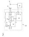
- FIG. 3 is the working principle of a FIG. 4 illustrated playback system 100 according to the present invention.
- This in FIG. 4 illustrated audio playback system 100 is used to reproduce audio signals in a vehicle interior, wherein the audio signals from different audio sources 10, 12, such as a C [ompact] D [isc], a radio or the like, can be generated.
- the playback system 100 has a loudspeaker device 50 and an audio processor 20 arranged in the signal path between the audio sources 10, 12 and the loudspeaker device 50 with two freely adjustable digital equalizers 22, 24, via which the signals of the different audio sources 10, 12 are supplied to the loudspeaker device 50 ;
- two freely adjustable digital equalizers 22, 24 may be provided.
- a control processor 30 sends suitable filter parameters to the audio processor 20 via a control bus 34.
- the playback system 100 further comprises a noise generator 40, via which the equalizers 22, 24, a noise signal can be supplied.
- the noise generator 40 is implemented here as additional software in the audio processor 20 and can be started if necessary via the control processor 30.
- the noise signal may also be generated by an external noise source as an additional audio source, for example, by using a corresponding C [ompact] D [isc] or by using an appropriately tuned tuner.
- control processor 30 has means by which the filter parameters can be adjusted so that the equalizers 22, 24 have a bandpass characteristic of narrow bandwidth, that is of order 8, with the center frequency f 0 being variable across the audio spectrum is.
- the speaker device 50 can be controlled by means of the noise generator 40 and the equalizers 22, 24 with a bandpass noise signal.
- the control processor 30 varies the filter parameters in a defined time sequence so that the center frequency f 0 of the bandpass filter decreases, for example, in the third of the frequency to be set to the lowest frequency to be set.
- the signals which are then emitted in each case via the speaker device 50 in the vehicle interior, are detected by means of a microphone 60 and evaluated with suitable evaluation means 70 for determining the frequency response of the vehicle interior.
- the detected by the microphone 60 signals are amplified in an operational amplifier circuit, logarithmized and rectified, so that at the output of this circuit is applied a DC voltage.
- the magnitude of this DC voltage is proportional to the sound level or the sound pressure in the vehicle interior for the frequency band that is set by the respective bandpass noise signal.
- the DC voltage representative DC voltage is sampled by an analogue / digital converter 32 of the control processor 30, so that the control processor 30, after tuning all the frequencies or frequency bands to be measured with the corresponding voltage values, obtains an accurate image of the acoustic frequency response of the vehicle interior is present.
- a frequency response here only the magnitude frequency response or the amplitude response is called and not the phase response.
- control processor 30 in a second method step [b] (cf. FIG. 3 ) determines a lower limit frequency below which the sound pressure falls below a sound pressure threshold value related to the mean sound pressure.
- a final process step [c] (cf. FIG. 3 )
- the filter parameters, in particular the boost G, the Q and the center frequency f 0 of the bass boost filter unit 26 are then automatically set, the increase of the bass level P is thus reduced in such a way as the limit frequency fc increases or the center frequency f 0 of the bass boosting filter unit 26 increases (cf. FIG. 2B ), that the isophones (cf. FIG. 1 ) are not exceeded in the remaining reproducible bass frequency range.
- Compliance with this relationship may or may not be associated with automatically determining the limit / center frequencies f c and f 0 , respectively; in other words, this means that the above-described functional relationship should be observed both when manually adjusting the limit / center frequency fc or f 0 of the bass boost filter unit 26 and when automatically setting the limit / center frequency f c or f 0 of the bass boost filter unit 26.
- the feature that the increase of the bass level P with increasing cutoff frequency f c (-> shelving filter) or with increasing center frequency f 0 (-> resonance filter) is reduced such that the isophones in the remaining reproducible bass frequency range not exceeded be associated with the feature that the filter parameters of the bass boost filter unit 26 are automatically adjusted so that the center frequency f 0 of the bass boost filter unit 26 is just above the determined cutoff frequency; This synergistically results in an excessive increase
- there is an automatic optimization of the auricular bass level boost is an automatic optimization of the auricular bass level boost.
- normalized equalizer pattern curves with different quality can also be stored in the audio processor 20.
- the above-described automatic auditory bass level increase as a function of the center frequency f 0 and the cutoff frequency f c of the loudness filter 26 at a product 100 with adjustable loudness filter limit or center frequency by measuring the loudness function easily detect allows ( ⁇ -> Loudness optimization on audio playback system 100), because on the one hand a frequency response measurement must be activated by the user (-> manual), and on the other hand, the optimization can be detected by measuring the loudness curves for frequency response measurements in various audio systems ,
Landscapes
- Tone Control, Compression And Expansion, Limiting Amplitude (AREA)
- Circuit For Audible Band Transducer (AREA)
Description
Die vorliegende Erfindung betrifft ein Verfahren gemäß dem Oberbegriff des Anspruchs 1 (vgl. Druckschrift
Die vorliegende Erfindung betrifft des weiteren ein Wiedergabesystem gemäß dem Oberbegriff des Anspruchs 5.The present invention further relates to a reproduction system according to the preamble of claim 5.
Die Erfindung geht von aus der Praxis bekannten Autoradiogeräten aus, die auf der sogenannten "2IC-Technologie" basieren, bei der das Audio-Wiedergabegerät und insbesondere dessen Tuner mit einer insbesondere digitalen Empfängereinheit, beispielsweise mit einem "digital receiver" (sogenannter "digiceiver"), versehen ist. Dies bedeutet mit anderen Worten, dass bereits im Empfangsteil des Tuners das hochfrequente Signal der Z[wischen]F[requenz]-Stufe bei beispielsweise 10,7 Megahertz in Bits und Bytes umgesetzt wird und daran anschließend bis zu den Endstufen konsequent auf digitaler Ebene weiterverarbeitet wird.The invention is based on known from practice car radio equipment based on the so-called "2IC technology", in which the audio playback device and in particular its tuner with a particular digital receiver unit, for example with a "digital receiver" (so-called "digiceiver" ) is provided. In other words, this means that already in the receiving part of the tuner, the high-frequency signal of the Z [wischen] F [requency] stage is converted into bits and bytes at 10.7 megahertz, for example, and then further processed consistently to the final stages on a digital level becomes.
Bei derartigen Autoradiogeräten sind beispielsweise zwei oder drei frei programmierbare Audiofilter in den Signalpfad integriert. Diese digitalen parametrischen Equalizer (= DPE) stehen dem Benutzer zur Verfügung, um Unzulänglichkeiten der Akustik im Fahrzeuginnenraum zu kompensieren. Der Benutzer kann jedes Filter in bezug auf bestimmte Filterparameter, wie etwa in bezug auf die Dämpfung, in bezug auf die Güte, das heißt die Filterbreite, in bezug auf die Mittenfrequenz und/oder in bezug auf die Verstärkung variieren, um Überhöhungen und sogenannte Löcher im akustischen Frequenzgang des Fahrzeuginnenraums auszugleichen.In such car radio devices, for example, two or three freely programmable audio filters are integrated into the signal path. These digital parametric equalizers (= DPE) are available to the user to compensate for inadequacies of the acoustics in the vehicle interior. The user may vary each filter with respect to certain filter parameters, such as attenuation, quality, that is, filter width, center frequency, and / or gain, overshoots and so-called holes compensate in the acoustic frequency response of the vehicle interior.
Im Zusammenhang mit dem akustischen Frequenzgang oder allgemeiner mit dem Lautstärkeempfinden des menschlichen Gehörs ist zu bedenken, dass dieses Lautstärkeempfinden über den hörbaren Frequenzbereich unterschiedlich ausgeprägt ist. Dies bedeutet mit anderen Worten, daß die Empfindlichkeit des menschlichen Gehörs nicht konstant über der Frequenz ist, sondern zu hohen Frequenzen und in noch stärkerem Maße zu niedrigen Frequenzen hin abnimmt. Dieser Effekt tritt mit sinkendem Schalldruckpegel verstärkt auf und wird, wie in
Um zum Beispiel bei einer Audiofrequenz von einhundert Hertz den gleichen Lautstärkeeindruck wie bei einer Frequenz von einem Kilohertz zu erzielen, ist ein wesentlich höherer Schalldruck erforderlich. Dieser Zusammenhang wird durch die Darstellung der vorerwähnten Linien gleicher Lautheit in einem Schalldruck/Frequenz-Diagramm dargestellt (vgl.
Zum Kompensieren dieses Effekts verfügen Systeme zum Wiedergeben von Audiosignalen häufig über eine Vorrichtung zum selektiven Anheben des Pegels der Bässe bei niedriger Wiedergabelautstärke; bei manchen Systemen werden die Höhen ebenfalls ein wenig angehoben. Diese als "gehörrichtige Lautstärkekorrektur" oder "Loudness Control" bezeichnete Vorrichtung soll die vom Zuhörer wahrgenommene Lautheit des Audiosignals unabhängig von der Wiedergabelautstärke über das ganze Hörfrequenzspektrum konstant halten, das heißt ein spektral ausgewogenes Klangbild gewährleisten.To compensate for this effect, audio signal reproduction systems often have a device for selectively raising the level of low-volume bass; Some systems also raise the altitudes a bit. This device, referred to as "aurally correct volume correction" or "loudness control", is intended to keep the loudness of the audio signal perceived by the listener constant independently of the playback volume over the entire hearing frequency spectrum, ie to ensure a spectrally balanced sound image.
Zum Einsatz kommen hierbei in der Regel Rekursivfilter erster Ordnung oder zweiter Ordnung, die entweder als Resonanzfilter oder als Shelvingfilter konfiguriert sind. Während Resonanzfilter durch die Parameter Anhebung G, Güte Q und Mittenfrequenz f0 charakterisiert werden und dazu geeignet sind, ein beliebiges schmales Frequenzband anzuheben, zeichnen sich Shelvingfilter dadurch aus, daß mit ihrer Hilfe der gesamte Frequenzbereich unterhalb bzw. oberhalb einer gewissen Grenzfrequenz fc angehoben wird, wobei die Filtersteilheit allein durch die Filterordnung festgelegt ist.As a rule, recursive filters of first order or second order are used, which are configured either as resonant filters or as shelving filters. While resonant filter by raising the parameters G, quality Q and center frequency f 0 are characterized and are suitable for raising any narrow frequency band, shelving filters are characterized by the fact that with their help, the entire frequency range is raised below or above a certain limit frequency f c , the filter slope alone is determined by the filter order.
Ein Problem bei der Realisierung einer gehörrichtigen Lautstärkekorrektur besteht oftmals darin, daß die eingesetzten Lautsprechersysteme nur sehr unzureichend in der Lage sind, die notwendigerweise anzuhebenden tiefen Frequenzen wiederzugeben. Die zu sehr tiefen Frequenzen stark zunehmende Pegelanhebung bleibt unter diesen Umständen einerseits akustisch wirkungslos und führt andererseits zu unnötiger Übersteuerung der Leistungsverstärkerstufen und der Lautsprecher, die sich zumindest in einem erhöhten Klirrfaktor äußert.A problem in the realization of aurally correct volume is often that the speaker systems used are very inadequate to reproduce the necessarily low frequencies to be lifted. The level increase, which increases sharply to very low frequencies, on the one hand remains acoustically ineffective under these circumstances and on the other hand leads to unnecessary overdriving of the power amplifier stages and the loudspeakers, which manifests itself in at least an increased harmonic distortion.
Aus diesem Grunde bieten einige Audiowiedergabesysteme bereits die Möglichkeit, die Filtergrenzfrequenz fc bzw. die Filtermittenfrequenz f0 so weit nach oben zu verschieben, bis sich ein hörbarer Effekt einstellt. Allerdings wird bei allen bislang bekannten Wiedergabesystemen die vorbeschriebene selektive Pegelanhebung gemäß
Eine derartige herkömmliche Vorgehensweise wird jedoch für den Fall einer angehobenen Grenzfrequenz fc bzw. Mittenfrequenz f0 des Baßanhebungsfilters den psychoakustischen Erkenntnissen nicht gerecht, denn in diesem Falle werden die tiefen Frequenzen übermäßig stark angehoben.However, such a conventional approach does not do justice to the psychoacoustic findings in the case of a raised cutoff frequency f c or center frequency f 0 of the bass boost filter, because in this case the low frequencies are raised excessively.
Ausgehend von den vorstehend dargelegten Nachteilen und Unzulänglichkeiten sowie unter Würdigung des umrissenen Standes der Technik liegt der vorliegenden Erfindung die Aufgabe zugrunde, ein Verfahren der eingangs genannten Art sowie ein Wiedergabesystem der eingangs genannten Art so weiterzuentwickeln, daß eine übermäßige Anhebung des Baßpegels vermieden wird.Based on the disadvantages and inadequacies set out above and in appreciation of the state of the art outlined, the present invention has the object, a method of the type mentioned and a reproduction system of the type mentioned so that an excessive increase in the bass level is avoided.
Diese Aufgabe wird gemäß der Lehre der vorliegenden Erfindung durch ein Verfahren mit den im Anspruch 1 genannten Merkmalen sowie durch ein Wiedergabesystem mit den im Anspruch 5 genannten Merkmalen gelöst. Vorteilhafte Ausgestaltungen und zweckmäßige Weiterbildungen der vorliegenden Erfindung sind in den jeweiligen Unteränsprüchen gekennzeichnet.This object is achieved according to the teaching of the present invention by a method having the features mentioned in claim 1 and by a display system having the features mentioned in claim 5. Advantageous embodiments and expedient developments of the present invention are characterized in the respective subclaims.
Mithin ist der Kern der vorliegenden Erfindung in einem Verfahren zur gehörrichtigen Frequenzgangkorrektur im Baßfrequenzbereich zu sehen, bei der infolge zusätzlicher geeigneter Berücksichtigung der eingestellten Filtergrenzfrequenz fc bzw. der eingestellten Filtermittenfrequenz f0 eine psychoakustisch sinnvolle Anhebung des Baßpegels P bei gleichzeitiger Minimierung von Systemübersteuerungen erzielt wird; mithin liegt eine gehörrichtige Baßpegelanhebung als Funktion der Filtereinsatzfrequenz vor.Thus, the core of the present invention is to be seen in a method for auricular frequency response correction in the bass frequency range, in which due to additional appropriate consideration of the set filter cutoff frequency f c or the set filter center frequency f 0 a psychoacoustically meaningful increase in the bass level P is achieved while minimizing system overrides ; Consequently, there is an auricular bass level increase as a function of the filter insert frequency.
Dies wird erfindungsgemäß erreicht durch ein Verfahren zum vorzugsweise automatischen Optimieren der gehörrichtigen Anhebung des Baßpegels P auf das Audiowiedergabesystem, bei dem der bzw. die Filterparameter der Baßanhebungsfiltereinheit so eingestellt wird bzw. werden, daß die Anhebung des Baßpegels P mit steigender Grenzfrequenz fc bzw. mit steigender Mittenfrequenz f0 der Baßanhebungsfiltereinheit derart reduziert wird, daß die Isophonen im verbleibenden wiedergebbaren Baßfrequenzbereich nicht überschritten werden.This is achieved according to the invention by a method for preferably automatically optimizing the aurally correcting of the bass level P to the audio reproduction system, in which the or the filter parameters of the bass boost filter unit is set so that the increase of the bass level P with increasing cutoff frequency f c or is reduced as the center frequency f 0 of the bass boost filter unit increases is that the isophones are not exceeded in the remaining reproducible bass frequency range.
Mit der vorliegenden Erfindung wird dem Benutzer also die schwierige Aufgabe der Anpassung der Baßanhebungsfiltereinheit(en) an die spezielle Akustik seines Fahrzeuginnenraums abgenommen.Thus, with the present invention, the user is faced with the difficult task of adapting the bass boost filter unit (s) to the particular acoustics of its vehicle interior.
Wenn das Einhalten eines funktionellen Zusammenhangs zwischen der Mittenfrequenz f0 der Baßanhebungsfiltereinheit und dem gehörrichtigen Anheben des Baßpegels P nicht mit einem manuellen Einstellen, sondern mit einem automatischen Bestimmen dieser Mittenfrequenz f0 einhergeht, so wird vor dem Einstellen des mindestens einen Filterparameters der Baßanhebungsfiltereinheit
- zunächst der akustische Frequenzgang des Fahrzeuginnenraums ermittelt,
- dann der mittlere Schalldruck ermittelt und
- dann eine Grenzfrequenz bestimmt, unterhalb derer der Schalldruck einen auf den mittleren Schalldruck bezogenen Schalldruckschwellwert unterschreitet.
- first determines the acoustic frequency response of the vehicle interior,
- then the mean sound pressure is determined and
- then determines a cutoff frequency below which the sound pressure falls below a sound pressure threshold based on the average sound pressure.
Im Detail wird zunächst der Frequenzgang des vorliegenden Audiowiedergabesystems mithilfe geeigneter Vorkehrungen ermittelt. Im Anschluß wird der gemessene Frequenzgang hinsichtlich des Wirkungsgrads des Wiedergabesystems im tieffrequenten Bereich ausgewertet.In detail, first, the frequency response of the present audio playback system is determined using appropriate precautions. Subsequently, the measured frequency response is evaluated in terms of the efficiency of the playback system in the low-frequency range.
Aus dem gemessenen Frequenzgang kann zunächst der mittlere Schalldruck ermittelt werden. Im Anschluß daran wird der Frequenzpunkt im tieffrequenten Bereich ermittelt, unterhalb dessen der Schalldruck einen bestimmten, auf den mittleren Schalldruck bezogenen Grenzwert unterschreitet, zum Beispiel etwa drei Dezibel.From the measured frequency response, the average sound pressure can first be determined. Following this, the frequency point in the low-frequency range is determined, below which the sound pressure falls below a certain limit value related to the mean sound pressure, for example about three decibels.
Ein Baßanhebungsfilter wird nun genau so eingestellt, daß die Isophonen im verbleibenden wiedergebbaren Baßfrequenzbereich nicht überschritten werden; dies wird erreicht, indem die Anhebung des Baßpegels P mit steigender Grenzfrequenz fc bzw. mit steigender Mittenfrequenz f0 der Baßanhebungsfiltereinheit reduziert wird, so daß eine Pegelkennlinienschar in Abhängigkeit von der Filtergrenzfrequenz fc (--> Shelvingfilter) bzw. von der Filtermittenfrequenz f0 (--> Resonanzfilter) entsteht.A bass boost filter is now set exactly so that the isophones are not exceeded in the remaining reproducible bass frequency range; This is achieved by the increase of the bass level P is reduced with increasing cutoff frequency f c and with increasing center frequency f 0 of the bass boost filter unit, so that a level characteristic set in dependence on the filter cutoff frequency f c (-> shelving filter) and the filter center frequency f 0 (-> resonance filter) is created.
Auf diese Weise wird einerseits sichergestellt, daß die Baßanhebung auch akustisch wirksam ist, andererseits wird das System nicht überlastet, denn der Frequenzgang des Baßanhebungsfilters bleibt im Falle der Ausgestaltung als mindestens ein Shelvingfilter unterhalb der Grenzfrequenz fc konstant bzw. fällt im Falle der Ausgestaltung als mindestens ein Resonanzfilter unterhalb der Mittenfrequenz f0 wieder ab.In this way, on the one hand ensures that the bass boost is also acoustically effective, on the other hand, the system is not overloaded, because the frequency response of Baßaufhebungsfilters remains in the case of the embodiment as at least one shelving below the cutoff frequency f c constant or falls in the case of the embodiment as at least one resonant filter below the center frequency f 0 again.
Des weiteren wird ein Wiedergabesystem der eingangs genannten Art vorgeschlagen, das zur gehörrichtigen Anhebung des Baßpegels P, das heißt zum vorzugsweise automatischen Einstellen der mindestens einen Baßanhebungsfiltereinheit erfindungsgemäß einen Rauschgenerator umfaßt, über den sich dem der Baßanhebungsfiltereinheit zugeordneten Equalizer ein Rauschsignal zuführen läßt.Furthermore, a playback system of the type mentioned above is proposed, which for aurally correcting the bass level P, that is for preferably automatically adjusting the at least one bass boost filter unit according to the invention comprises a noise generator, via which the Baßaufhebungsfiltereinheit associated equalizer can supply a noise signal.
Außerdem weist der Steuerungsprozessor Mittel auf, über die die Filterparameter so einstellbar sind, daß der Equalizer eine Bandpaßcharakteristik mit schmaler Bandbreite aufweist, wobei die Mittenfrequenz über dem Audiospektrum variierbar ist.In addition, the control processor includes means by which the filter parameters are adjustable such that the equalizer has a narrow bandwidth bandpass characteristic, the center frequency being variable over the audio spectrum.
Zum Erfassen des von der Lautsprechereinrichtung in den Fahrzeuginnenraum abgestrahlten Signals und zum Bestimmen des Frequenzgangs ist mindestens ein Mikrophon mit Auswertemitteln vorgesehen.For detecting the signal radiated by the loudspeaker device into the vehicle interior and for determining the frequency response, at least one microphone with evaluation means is provided.
Schließlich weist der Steuerungsprozessor noch Mittel auf, über die die Filterparameter unter Berücksichtigung des gemessenen Frequenzgangs einstellbar sind.Finally, the control processor also has means via which the filter parameters take into account the measured frequency response are adjustable.
Es ist erkannt worden, daß die einzumessenden Equalizer aufgrund ihrer Programmierbarkeit zunächst zur Bestimmung des akustischen Frequenzgangs des Fahrzeuginnenraums verwendet werden können, bevor eine Grenzfrequenz bestimmt werden kann, unterhalb derer der Schalldruck einen auf den mittleren Schalldruck bezogenen Schalldruckschwellwert unterschreitet.It has been recognized that due to their programmability, the equalizers to be measured can firstly be used to determine the acoustic frequency response of the vehicle interior, before a cutoff frequency can be determined, below which the sound pressure falls below a sound pressure threshold related to the mean sound pressure.
Des weiteren ist erfindungsgemäß erkannt worden, daß für die Bestimmung der gehörrichtigen Anhebung des Baßpegels P neben der eingestellten Lautstärke S zusätzlich die Filtergrenz- bzw. -mittenfrequenz fc bzw. f0 des Baßanhebungs- oder Loudnessfilters in geeigneter Weise zu berücksichtigen ist. Wie
Der Zusammenhang zwischen der Filtermitten-/-grenzfrequenz sowie der eingestellten Lautstärke S als Eingangsgrößen und der resultierenden Baßanhebung als Ausgangsgröße erfolgt über eine mathematische Funktion und kann, abhängig von den jeweiligen Gegebenheiten, in erfindungswesentlicher Weise kontinuierlich oder in Stufen erfolgen. Im Ergebnis erfolgt also eine automatische Optimierung einer gehörrichtigen Baßpegelanhebung, indem die Filterparameter der Baßanhebungsfiltereinheit in Abhängigkeit von oder als Funktion der Grenzfrequenz fc bzw. der Mittenfrequenz f0 eingestellt werden.The relationship between the filter center / cutoff frequency and the set volume S as input variables and the resulting bass boost as output variable takes place via a mathematical function and, depending on the particular circumstances, can be carried out continuously or in stages in a manner essential to the invention. As a result, there is thus an automatic optimization of a correct bass level increase by setting the filter parameters of the bass pickup filter unit as a function of or as a function of the cutoff frequency f c or the center frequency f 0 .
Es besteht also ein funktioneller Zusammenhang zwischen der Grenz/Mittenfrequenz fc bzw. f0 des Loudness-Filters und der notwendigen Verstärkung sowie der notwendigen Güte, der für eine wirklich gehörrichtige Lautheitskorrektur sinnvoll ist. Das Einhalten dieses Zusammenhangs kann, muß jedoch nicht mit einem automatischen Ermitteln der Grenz/Mittenfrequenz fc bzw. fc verknüpft sein.So there is a functional relationship between the limit / center frequency f c or f 0 of the loudness filter and the necessary gain and the necessary quality, which is for a really aurally Loudness correction makes sense. Adhering to this relationship may or may not be associated with automatically determining the boundary / center frequency f c or f c , respectively.
Dies bedeutet mit anderen Worten, daß der vorbeschriebene funktionelle Zusammenhang sowohl bei manuellem Verstellen der Grenz/Mittenfrequenz fc bzw. f0 als auch bei automatischem Einstellen der Grenz-/Mittenfrequenz fc bzw. f0 eingehalten werden sollte. Im letzteren Falle kann das Merkmal, daß die Anhebung des Baßpegels P mit steigender Grenzfrequenz fc bzw. mit steigender Mittenfrequenz f0 der Baßanhebungsfiltereinheit derart reduziert wird, daß die Isophonen im verbleibenden wiedergebbaren Baßfrequenzbereich nicht überschritten werden, in erfindungswesentlicher Weise mit dem Merkmal verknüpft werden, daß der bzw. die Filterparameter der Baßanhebungsfiltereinheit automatisch so eingestellt wird bzw. werden, daß die Mittenfrequenz der Baßanhebungsfiltereinheit gerade oberhalb der bestimmten Grenzfrequenz liegt.In other words, this means that the above-described functional relationship should be observed both with manual adjustment of the limit / center frequency f c or f 0 and with automatic setting of the limit / center frequency f c or f 0 . In the latter case, the feature that the increase of the bass level P with increasing cutoff frequency f c or with increasing center frequency f 0 of the bass boost filter unit is reduced such that the isophones are not exceeded in the remaining reproducible bass frequency range, be linked in essential to the invention with the feature in that the filter parameter (s) of the bass boost filter unit is / are automatically adjusted so that the center frequency of the bass boost filter unit is just above the determined cutoff frequency.
Hierdurch wird in synergetischer Weise zum einen eine übermäßige Anhebung des Baßpegels P vermieden, zum anderen erfolgt jedoch gleichwohl eine automatische Optimierung der gehörrichtigen Baßpegelanhebung. Ferner ist erfindungsgemäß erkannt worden, daß die Optimierung der gehörrichtigen Anhebung des Baßpegels P mithilfe einer entsprechenden Zusatzsoftware vom ohnehin vorhandenen Steuerungsprozessor des Autoradiogeräts vorgenommen werden kann.As a result, an excessive increase of the bass level P is avoided in a synergetic manner on the one hand, but on the other hand, however, there is nevertheless an automatic optimization of the auricular bass level boost. Furthermore, it has been recognized according to the invention that the optimization of the aurally correct increase of the bass level P can be carried out by means of an appropriate additional software from the already existing control processor of the car radio.
Im Ergebnis ist also im Rahmen der vorliegenden Erfindung kein zusätzliches Audiomodul mit digitalem Signalprozessor erforderlich, sondern lediglich eine Mikrophon-, Verstärkungs- und Gleichrichtungsschaltung, die an die im Steuerungsprozessor vorhandene A[nalog]/D[igital]-Wandlereinheit angekoppelt wird; hierdurch ist für die erfindungsgemäß vorgeschlagene Einstellung der Filterparameter in bezug auf die Baßpegelanhebung lediglich ein sehr geringer Mehraufwand an Hardware sowie an Software und mithin an Kosten erforderlich.As a result, therefore, in the context of the present invention, no additional audio module with a digital signal processor is required, but merely a microphone, amplification and rectification circuit, which is coupled to the A [nalog] / D [igital] converter unit present in the control processor; As a result, the setting of the filter parameters with respect to the bass level boost proposed according to the invention requires only a very small amount of additional hardware and of software and therefore costs.
Grundsätzlich gibt es verschiedene Möglichkeiten für die Ermittlung des akustischen Frequenzgangs des Fahrzeuginnenraums im Rahmen des vorliegenden Verfahrens. Gemäß einer vorteilhaften Ausgestaltungsform wird die Lautsprechereinrichtung des Wiedergabesystems nacheinander von Bandpaß-Rauschsignalen mit unterschiedlichen Mittenfrequenzen angesteuert. Die jeweils in Form eines Bandpaß-Rauschsignals eingestellten Frequenzbänder decken das gesamte Audiospektrum ab.In principle, there are various possibilities for determining the acoustic frequency response of the vehicle interior in the context of the present method. According to an advantageous embodiment, the loudspeaker device of the playback system is controlled successively by bandpass noise signals having different center frequencies. Each set in the form of a bandpass noise signal frequency bands cover the entire audio spectrum.
Der zu ermittelnde Frequenzgang wird nun in Form von Frequenzmeßpunkten für die einzelnen Frequenzbänder ermittelt. Als Frequenzmeßpunkt für ein bestimmtes Frequenzband kann einfach der Schallpegel des Signals bestimmt werden, das in diesem Fall von der Lautsprechereinrichtung in den Fahrzeuginnenraum abgestrahlt wird.The frequency response to be determined is now determined in the form of frequency measuring points for the individual frequency bands. As Frequenzmeßpunkt for a particular frequency band, the sound level of the signal can be easily determined, which is emitted in this case from the speaker device in the vehicle interior.
Im Hinblick auf eine Minimierung des Hardware-Aufwands sowie des Software-Aufwands erweist es sich als vorteilhaft, die Bandpaß-Rauschsignale zum Ermitteln des akustischen Frequenzgangs des Fahrzeuginnenraums mithilfe des einzustellenden Equalizers selbst zu erzeugen. Da dieser sowohl in seiner Mittenfrequenz als auch in seiner Güte frei programmierbar ist, können die Filterparameter so eingestellt werden, daß sich für den Equalizer eine Bandpaßcharakteristik mit schmaler Bandbreite bei vorgegebener Mittenfrequenz ergibt.In terms of minimizing the hardware overhead and software cost, it is advantageous to generate the bandpass noise signals to determine the acoustic frequency response of the vehicle interior using the equalizer to be set. Since this is freely programmable both in its center frequency and in its quality, the filter parameters can be set so that there is a bandpass characteristic for the equalizer with narrow bandwidth at a given center frequency.
Der Equalizer erzeugt dann aus einem ihm zugeführten Rauschsignal das gewünschte Bandpaß-Rauschsignal bzw. eine Abfolge von Bandpaß-Rauschsignalen, die das gesamte Audiospektrum abdecken.The equalizer then generates from a noise signal supplied thereto the desired bandpass noise signal or a sequence of bandpass noise signals covering the entire audio spectrum.
Werden die Filterparameter von mehreren digitalen Equalizern automatisch eingestellt, so ist es von Vorteil, die Filterparameter der einzelnen Equalizer nacheinander zu bestimmen, indem jeweils vor dem Bestimmen der Filterparameter eines Equalizers der bzw. die vorher eingestellten Equalizer auf den gemessenen Frequenzgang angewendet werden.If the filter parameters of several digital equalizers are set automatically, it is advantageous to determine the filter parameters of the individual equalizers in succession, in each case before determining the filter parameter of an equalizer or the previously set equalizers are applied to the measured frequency response.
Die vorliegende Erfindung betrifft schließlich die Verwendung des Verfahrens gemäß der vorstehend dargelegten Art und/oder des Wiedergabesystems gemäß der vorstehend dargelegten Art für Audiosignale in mindestens einem Fortbewegungsmittel, insbesondere im Innenraum mindestens eines Kraftfahrzeugs.Finally, the present invention relates to the use of the method according to the type and / or the reproduction system set forth above for audio signals in at least one means of locomotion, in particular in the interior of at least one motor vehicle.
Wie bereits voranstehend ausführlich erörtert, gibt es verschiedene Möglichkeiten, die Lehre der vorliegenden Erfindung in vorteilhafter Weise auszugestalten und weiterzubilden. Hierzu wird einerseits auf die den Ansprüchen 1 und 7 nachgeordneten Ansprüche verwiesen, andererseits werden weitere Ausgestaltungen, Merkmale und Vorteile der vorliegenden Erfindung nachstehend anhand des durch die
Es zeigt:
- Fig. 1
- ein gemäß l[nternational]S[tandardization]O[rganization] normiertes Diagramm für Kurven gleicher Lautstärke (= sogenannte Isophonen), die als Funktion des Schallpegeldrucks über der Frequenz aufgetragen sind;
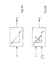
- Fig. 2A
- ein schematisches Diagramm einer Pegelkennlinie (= Baßanhebung P, aufgetragen über der Lautstärke S) einer konventionellen gehörrichtigen Baßpegelkorrektur gemäß dem Stand der Technik;
- Fig. 2B
- ein schematisches Diagramm einer in Abhängigkeit von der Filtergrenzfrequenz bzw. von der Filtermittenfrequenz gebildeten Pegelkennlinienschar (= Baßanhebung P, aufgetragen über der Lautstärke S) einer gehörrichtigen Baßpegelkorrektur nach dem Verfahren gemäß der vorliegenden Erfindung;
- Fig. 3
- ein schematisches Blockschaltbild (= Ablaufdiagramm) eines Ausführungsbeispiels für ein Verfahren gemäß der vorliegenden Erfindung; und
- Fig. 4
- eine schematische Prinzipdarstellung (= Blockdiagramm) eines Ausführungsbeispiels für ein Wiedergabesystem gemäß der vorliegenden Erfindung, das zum Durchführen des Verfahrens gemäß
Fig. 3 vorgesehen ist.
- Fig. 1
- a normalized standard for curves of equal loudness (= so-called isophones), plotted as a function of sound pressure over frequency, according to international standardization [Rganization];
- Fig. 2A
- a schematic diagram of a level characteristic (= bass boost P, plotted against the volume S) of a conventional aurally correct bass level correction according to the prior art;
- Fig. 2B
- a schematic diagram of a function of the filter cutoff frequency or the level characteristic curve formed by the filter center frequency (= bass boost P, plotted against the volume S) of an auricular bass level correction according to the method according to the present invention;
- Fig. 3
- a schematic block diagram (= flowchart) of an embodiment of a method according to the present invention; and
- Fig. 4
- a schematic schematic representation (= block diagram) of an embodiment of a playback system according to the present invention, which is used to carry out the method according to
Fig. 3 is provided.
In
Das in
Das Wiedergabesystem 100 weist eine Lautsprechereinrichtung 50 und einen im Signalpfad zwischen den Audioquellen 10, 12 und der Lautsprechereinrichtung 50 angeordneten Audioprozessor 20 mit zwei frei einstellbaren digitalen Equalizern 22, 24 auf, über die die Signale der unterschiedlichen Audioquellen 10, 12 der Lautsprechereinrichtung 50 zugeführt werden; selbstverständlich können hier auch mehr als zwei Equalizer 22, 24 vorgesehen sein.The
Zum Einstellen der Filterparameter, insbesondere zum Einstellen der Mittenfrequenz f0, sendet ein Steuerungsprozessor 30 über einen Steuerungsbus 34 geeignete Filterparameter an den Audioprozessor 20.To set the filter parameters, in particular for setting the center frequency f 0 , a
Zum Bestimmen bzw. zum Messen des Frequenzgangs des vorliegenden Audiosystems im Fahrzeuginnenraum (= Verfahrensschritt [a] gemäß
Alternativ hierzu kann das Rauschsignal auch von einer externen Rauschquelle als zusätzlicher Audioquelle erzeugt werden, zum Beispiel mithilfe einer entsprechenden C[ompact]D[isc] oder mithilfe eines in geeigneter Weise eingestellten Tuners.Alternatively, the noise signal may also be generated by an external noise source as an additional audio source, for example, by using a corresponding C [ompact] D [isc] or by using an appropriately tuned tuner.
Des weiteren weist der Steuerungsprozessor 30 Mittel auf, über die die Filterparameter so eingestellt werden können, daß die Equalizer 22, 24 eine Bandpaßcharakteristik mit schmaler Bandbreite, das heißt mit einer Güte der Größenordnung 8, aufweisen, wobei die Mittenfrequenz f0 über dem Audiospektrum variierbar ist. Auf diese Weise kann die Lautsprechereinrichtung 50 mithilfe des Rauschgenerators 40 und über die Equalizer 22, 24 mit einem Bandpaß-Rauschsignal angesteuert werden.Furthermore, the
Wenn das Einmessen der Equalizer 22, 24 beispielsweise durch Tastendruck gestartet worden ist, variiert der Steuerungsprozessor 30 die Filterparameter in definierter zeitlicher Abfolge so, daß die Mittenfrequenz f0 des Bandpaßfilters zum Beispiel im Terzabstand von der höchsten einzustellenden Frequenz bis zur tiefsten einzustellenden Frequenz abnimmt.If the calibration of the
Die Signale, die dann jeweils über die Lautsprechereinrichtung 50 in den Fahrzeuginnenraum abgestrahlt werden, werden mithilfe eines Mikrophons 60 erfaßt und mit geeigneten Auswertemitteln 70 zum Bestimmen des Frequenzgangs des Fahrzeuginnenraums ausgewertet.The signals, which are then emitted in each case via the
Hierzu werden die vom Mikrophon 60 erfaßten Signale in einer Operationsverstärkerschaltung verstärkt, logarithmiert und gleichgerichtet, so daß am Ausgang dieser Schaltung eine Gleichspannung anliegt. Die Größe dieser Gleichspannung ist proportional zum Schallpegel bzw. zum Schalldruck im Fahrzeuginnenraum für das Frequenzband, das durch das jeweilige Bandpaß-Rauschsignal eingestellt ist. Durch das Durchstimmen der Equalizer 22, 24 wird der Schallpegel für das gesamte Audiospektrum detektiert.For this purpose, the detected by the
Die den Schallpegel repräsentierende Gleichspannung wird von einem A[nalog]/D[igital]-Wandler 32 des Steuerungsprozessors 30 abgetastet, so daß dem Steuerungsprozessor 30 nach dem Durchstimmen aller zu messenden Frequenzen bzw. Frequenzbänder mit den entsprechenden Spannungswerten ein genaues Abbild des akustischen Frequenzgangs des Fahrzeuginnenraums vorliegt. Als Frequenzgang wird hier ausschließlich der Betragsfrequenzgang bzw. der Amplitudengang bezeichnet und nicht der Phasengang.The DC voltage representative DC voltage is sampled by an analogue /
Im Steuerungsprozessor 30 wird nun in einem zweiten Verfahrensschritt [b] (vgl.
In einem abschließenden Verfahrensschritt [c] (vgl.
Im Ergebnis erfolgt also eine automatische Optimierung einer gehörrichtigen Baßpegelanhebung, indem die Filterparameter der Baßanhebungsfiltereinheit 26 in Abhängigkeit von oder als Funktion der Grenzfrequenz fc bzw. der Mittenfrequenz f0 eingestellt werden. Es besteht also ein funktioneller Zusammenhang zwischen der Grenz-/Mittenfrequenz fc bzw. f0 des Loudness-Filters 26 und der notwendigen Verstärkung sowie der notwendigen Güte, der für eine wirklich gehörrichtige Lautheitskorrektur sinnvoll ist.As a result, there is thus an automatic optimization of a correct bass level increase by setting the filter parameters of the bass
Das Einhalten dieses Zusammenhangs kann, muß jedoch nicht mit einem automatischen Ermitteln der Grenz-/Mittenfrequenz fc bzw. f0 verknüpft sein; dies bedeutet mit anderen Worten, daß der vorbeschriebene funktionelle Zusammenhang sowohl bei manuellem Verstellen der Grenz/Mittenfrequenz fc bzw. f0 der Baßanhebungsfiltereinheit 26 als auch bei automatischem Einstellen der Grenz-/Mittenfrequenz fc bzw. f0 der Baßanhebungsfiltereinheit 26 eingehalten werden sollte.Compliance with this relationship may or may not be associated with automatically determining the limit / center frequencies f c and f 0 , respectively; in other words, this means that the above-described functional relationship should be observed both when manually adjusting the limit / center frequency fc or f 0 of the bass
In erfindungswesentlicher Weise kann das Merkmal, daß die Anhebung des Baßpegels P mit steigender Grenzfrequenz fc (--> Shelvingfilter) bzw. mit steigender Mittenfrequenz f0 (--> Resonanzfilter) derart reduziert wird, daß die Isophonen im verbleibenden wiedergebbaren Baßfrequenzbereich nicht überschritten werden, mit dem Merkmal verknüpft werden, daß der bzw. die Filterparameter der Baßanhebungsfiltereinheit 26 automatisch so eingestellt wird bzw. werden, daß die Mittenfrequenz f0 der Baßanhebungsfiltereinheit 26 gerade oberhalb der bestimmten Grenzfrequenz liegt; hierdurch wird in synergetischer Weise zum einen eine übermäßige Anhebung des Baßpegels vermieden, zum anderen erfolgt jedoch gleichwohl eine automatische Optimierung der gehörrichtigen Baßpegelanhebung.In essential to the invention, the feature that the increase of the bass level P with increasing cutoff frequency f c (-> shelving filter) or with increasing center frequency f 0 (-> resonance filter) is reduced such that the isophones in the remaining reproducible bass frequency range not exceeded be associated with the feature that the filter parameters of the bass
Der gesamte Zusatzaufwand gegenüber einem Autoradiogerät, dessen Equalizer nicht automatisch einstellbar sind, besteht in einer Zusatzhardware 40 bzw. in einer Zusatzsoftware zum Generieren eines Rauschsignals, in einer Zusatzsoftware im Steuerungsprozessor 30, die die Ablaufsteuerung des Einmeßvorgangs (= Verfahrensschritt [a]; vgl.
Zum Ermitteln der bestmöglichen Einstellung der Filterparameter können im Audioprozessor 20 auch normierte Equalizer-Musterkurven mit unterschiedlicher Güte abgespeichert sein.To determine the best possible setting of the filter parameters, normalized equalizer pattern curves with different quality can also be stored in the
Abschließend sei noch angemerkt, daß sich die vorbeschriebene automatische gehörrichtige Baßpegelanhebung als Funktion der Mittenfrequenz f0 bzw. der Grenzfrequenz fc des Loudness-Filters 26 bei einem Erzeugnis 100 mit einstellbarer Loudness-Filter-Grenz- bzw. Mittenfrequenz durch Vermessung der Loudnessfunktion problemlos nachweisen läßt (<--> Loudness-Optimierung am Audiowiedergabesystem 100), denn zum einen muß eine Frequenzgangmessung vom Benutzer aktivierbar sein (--> Bedienungsanleitung), und zum anderen kann die Optimierung durch Messen der Loudness-Kurven nach Frequenzgangmessungen in verschiedenen Audiosystemen nachgewiesen werden.Finally, it should be noted that the above-described automatic auditory bass level increase as a function of the center frequency f 0 and the cutoff frequency f c of the
Claims (8)
- Method for boosting the bass level (P) of a reproduction system (100) for audio signals in an aurally appropriate fashion by means of adjustment of at least one filter parameter of at least one bass boost filter unit (26) associated with the reproduction system (100), wherein the at least one filter parameter of the base boost filter unit (26) is adjusted such that the boost in the bass level (P) is reduced as the filter cut-off frequency (fc) of the bass boost filter unit (26) rises or as the centre frequency (f0) of the bass boost filter unit (26) rises such that the isophones in the remaining reproducible bass frequency range are not exceeded,
characterized
in that the at least one filter parameter of the bass boost filter unit (26) is automatically adjusted such that the centre frequency (f0) of the bass boost filter unit (26) is just above a particular cutoff frequency, wherein[a] first of all the acoustic frequency response and the average sound pressure are ascertained and[b] then the cut-off frequency below which the sound pressure is below a sound pressure threshold value based on the average sound pressure is determined before[c] the at least one filter parameter of the bass boost filter unit (26) is adjusted. - Method according to Claim 1, characterized in that the acoustic frequency response is ascertained by- successively actuating at least one loudspeaker device (50) of the reproduction system (100) using bandpass noise signals with different centre frequencies (f0), wherein the respective frequency bands adjusted in the form of at least one bandpass noise signal cover the entire audio spectrum, and- ascertaining the frequency response in the form of frequency measurement points for the individual frequency bands, wherein a frequency measurement point determined for a particular frequency band is the sound level of the signal that is emitted by the loudspeaker device (50) in this case.
- Method according to Claim 2, characterized in that the bandpass noise signals for ascertaining the acoustic frequency response are produced by means of at least one digital equalizer (22, 24) that is associated with the reproduction system (100), and to which particularly the bass boost filter unit (26) is assigned, by- supplying at least one noise signal to the equalizer (22, 24) and- adjusting the at least one filter parameter of the bass boost filter unit (26) such that a bandpass characteristic having a narrow bandwidth at a prescribed centre frequency (f0) is obtained for the equalizer (22, 24).
- Method according to at least one of Claims 1 to 3, wherein the at least one filter parameter is automatically adjusted by means of at least two digital equalizers (22, 24), characterized in that the filter parameters of the individual equalizers (22, 24) are determined successively by applying the previously adjusted equalizer(s) (22, 24) to the ascertained frequency response each time before the filter parameters of an equalizer (22, 24) are determined.
- Reproduction system (100) for audio signals that is able to be used to carry out a method according to at least one of Claims 1 to 4 by adjusting at least one filter parameter of at least one bass boost filter unit (26) associated with at least one digital equalizer (22, 24) of the reproduction system (100),- having at least one loudspeaker device (50) and- having at least one audio processor (20) that has the equalizer (22, 24) and that- is arranged in a signal path between at least one signal source (10, 12) and the loudspeaker device (50) and- is connected to at least one control processor (30) by means of at least one control bus (34), characterized- in that at least one noise generator (40) is provided that can be used to supply at least one noise signal to the equalizer (22, 24),- in that the control processor (30) has means that are used to adjust the at least one filter parameter such that the equalizer (22, 24) has a bandpass characteristic having a narrow bandwidth, wherein the centre frequency (f0) can be varied over the audio spectrum,- in that at least one microphone (60) having evaluation means (70) for capturing the signal emitted by the loudspeaker device (50) and for determining the frequency response is provided, and- in that the control processor (30) has means that are used to adjust the at least one filter parameter by taking into account the measured frequency response and to determine the cut-off frequency below which the sound pressure is below a sound pressure threshold value based on the average sound pressure.
- Reproduction system according to Claim 5, characterized in that the noise generator (40)- is implemented in the audio processor (20) and/or- is provided in the form of an additional external signal source.
- Reproduction system according to Claim 5 or 6, characterized in that the evaluation means (70) for evaluating the signal captured by the microphone (60) have means for amplifying, for logarithmizing and for rectifying the signal.
- Use of the method according to at least one of Claims 1 to 4 and/or of the reproduction system (100) according to at least one of Claims 5 to 7 for audio signals in at least one means of transport, particularly in the interior of at least one motor vehicle.
Applications Claiming Priority (2)
| Application Number | Priority Date | Filing Date | Title |
|---|---|---|---|
| DE10225145 | 2002-06-06 | ||
| DE10225145A DE10225145A1 (en) | 2002-06-06 | 2002-06-06 | Proper bass level boosting method and associated playback system |
Publications (3)
| Publication Number | Publication Date |
|---|---|
| EP1369994A2 EP1369994A2 (en) | 2003-12-10 |
| EP1369994A3 EP1369994A3 (en) | 2004-11-10 |
| EP1369994B1 true EP1369994B1 (en) | 2013-09-11 |
Family
ID=29432673
Family Applications (1)
| Application Number | Title | Priority Date | Filing Date |
|---|---|---|---|
| EP03006909.0A Expired - Lifetime EP1369994B1 (en) | 2002-06-06 | 2003-03-26 | Method for boosting low frequencies adapted to an auditory system and corresponding reproduction system |
Country Status (3)
| Country | Link |
|---|---|
| US (1) | US20040032959A1 (en) |
| EP (1) | EP1369994B1 (en) |
| DE (1) | DE10225145A1 (en) |
Families Citing this family (15)
| Publication number | Priority date | Publication date | Assignee | Title |
|---|---|---|---|---|
| JP2005136647A (en) * | 2003-10-30 | 2005-05-26 | New Japan Radio Co Ltd | Bass booster circuit |
| US7711129B2 (en) * | 2004-03-11 | 2010-05-04 | Apple Inc. | Method and system for approximating graphic equalizers using dynamic filter order reduction |
| DE102004055738B4 (en) * | 2004-11-18 | 2010-11-04 | Fachhochschule Jena | Signal processing unit and signal processing method |
| US8238576B2 (en) * | 2005-06-30 | 2012-08-07 | Cirrus Logic, Inc. | Level dependent bass management |
| US8189812B2 (en) * | 2007-03-01 | 2012-05-29 | Microsoft Corporation | Bass boost filtering techniques |
| US8275152B2 (en) * | 2007-09-21 | 2012-09-25 | Microsoft Corporation | Dynamic bass boost filter |
| KR101068227B1 (en) * | 2009-06-23 | 2011-09-28 | 주식회사 더바인코퍼레이션 | Clarity Improvement Device and Voice Output Device Using the Same |
| WO2012177572A2 (en) * | 2011-06-24 | 2012-12-27 | Beats Electronics, Llc | Optimization method for audio playback systems |
| US9264823B2 (en) * | 2012-09-28 | 2016-02-16 | Apple Inc. | Audio headset with automatic equalization |
| US10034092B1 (en) | 2016-09-22 | 2018-07-24 | Apple Inc. | Spatial headphone transparency |
| US11166099B2 (en) * | 2019-09-27 | 2021-11-02 | Apple Inc. | Headphone acoustic noise cancellation and speaker protection or dynamic user experience processing |
| US11361745B2 (en) | 2019-09-27 | 2022-06-14 | Apple Inc. | Headphone acoustic noise cancellation and speaker protection |
| US11355096B1 (en) | 2020-09-16 | 2022-06-07 | Apple Inc. | Adaptive feedback processing for consistent headphone acoustic noise cancellation |
| US11206004B1 (en) | 2020-09-16 | 2021-12-21 | Apple Inc. | Automatic equalization for consistent headphone playback |
| US11688383B2 (en) | 2021-08-27 | 2023-06-27 | Apple Inc. | Context aware compressor for headphone audio feedback path |
Citations (2)
| Publication number | Priority date | Publication date | Assignee | Title |
|---|---|---|---|---|
| DE10017277A1 (en) * | 2000-04-06 | 2001-11-22 | Harman Audio Electronic Sys | Setting audio signal loudness correctly for listening involves first damping depending on loudness setting, frequency-selective filtering, second damping and summing damped signals |
| EP1372262A2 (en) * | 2002-06-06 | 2003-12-17 | Robert Bosch Gmbh | Method for adjusting filter parameters and associated reproducing apparatus |
Family Cites Families (6)
| Publication number | Priority date | Publication date | Assignee | Title |
|---|---|---|---|---|
| FR2478409A1 (en) * | 1980-03-13 | 1981-09-18 | Desclaux Jean Francois | AUTOMATIC CORRECTOR FOR FREQUENCY TRANSMISSION CHARACTERISTICS OF AN ELECTROACOUSTIC CHANNEL |
| DE4011704A1 (en) * | 1990-04-11 | 1991-10-17 | Blaupunkt Werke Gmbh | ARRANGEMENT FOR IMPROVING THE PLAYBACK QUALITY OF AUDIO SIGNALS |
| US6885752B1 (en) * | 1994-07-08 | 2005-04-26 | Brigham Young University | Hearing aid device incorporating signal processing techniques |
| DE19630405C2 (en) * | 1996-07-26 | 1998-07-02 | Sgs Thomson Microelectronics | Device for changing the corner frequency of a low-pass filter |
| DE10027618B4 (en) * | 1999-06-19 | 2013-11-14 | Ascendo Gmbh | transducer |
| US7016509B1 (en) * | 2000-09-08 | 2006-03-21 | Harman International Industries, Inc. | System and method for varying low audio frequencies inversely with audio signal level |
-
2002
- 2002-06-06 DE DE10225145A patent/DE10225145A1/en not_active Withdrawn
-
2003
- 2003-03-26 EP EP03006909.0A patent/EP1369994B1/en not_active Expired - Lifetime
- 2003-06-04 US US10/454,988 patent/US20040032959A1/en not_active Abandoned
Patent Citations (2)
| Publication number | Priority date | Publication date | Assignee | Title |
|---|---|---|---|---|
| DE10017277A1 (en) * | 2000-04-06 | 2001-11-22 | Harman Audio Electronic Sys | Setting audio signal loudness correctly for listening involves first damping depending on loudness setting, frequency-selective filtering, second damping and summing damped signals |
| EP1372262A2 (en) * | 2002-06-06 | 2003-12-17 | Robert Bosch Gmbh | Method for adjusting filter parameters and associated reproducing apparatus |
Also Published As
| Publication number | Publication date |
|---|---|
| DE10225145A1 (en) | 2003-12-18 |
| US20040032959A1 (en) | 2004-02-19 |
| EP1369994A2 (en) | 2003-12-10 |
| EP1369994A3 (en) | 2004-11-10 |
Similar Documents
| Publication | Publication Date | Title |
|---|---|---|
| EP1366564B1 (en) | Device for the noise-dependent adjustment of sound volumes | |
| EP1369994B1 (en) | Method for boosting low frequencies adapted to an auditory system and corresponding reproduction system | |
| DE69933141T2 (en) | TONE PROCESSOR FOR ADAPTIVE DYNAMIC RANGE IMPROVEMENT | |
| DE10105184A1 (en) | Method for automatically adjusting a digital equalizer and playback device for audio signals to implement such a method | |
| DE69826331T2 (en) | METHOD FOR IN-SITU CORRECTING OR ADJUSTING A SIGNAL PROCESSING METHOD IN A HEARING DEVICE WITH THE HELP OF A REFERENCE SIGNAL PROCESSOR | |
| DE10260657B4 (en) | Audio amplifier with voltage limiting in response to the spectral content | |
| DE19734969A1 (en) | Device for reproducing audio signals | |
| DE3222495A1 (en) | Automatic volume control device | |
| DE3006810C2 (en) | ||
| EP1372262B1 (en) | Method for adjusting filter parameters and associated reproducing apparatus | |
| DE102007033484A1 (en) | hearing Aid | |
| DE10020756B4 (en) | Device and method for the noise-dependent adaptation of an acoustic useful signal | |
| EP1850634A2 (en) | Method for setting a hearing aid with high frequency amplification | |
| DE2456468C3 (en) | Electroacoustic «sound reproduction device with an amplifier controlled by a noise detector | |
| DE3910724C2 (en) | Device for adjusting the amplification of a sound signal in a vehicle | |
| EP1416764B1 (en) | Method of setting parameters of a hearing aid and device for carrying out this method | |
| EP1342390B1 (en) | Method for reproducing audio signals of at least two different sources | |
| DE102016103297B4 (en) | Device and method for configuring a user-specific hearing system | |
| EP1351550A1 (en) | Method for adapting a signal amplification in a hearing aid and a hearing aid | |
| EP0972340B1 (en) | Automatic volume control in an audio-signal reproduction facility, and device required | |
| DE102011055533B4 (en) | Consumer electronics device | |
| DE102015200961B4 (en) | Digital wireless audio transmission system with optimized dynamics | |
| EP4134954B1 (en) | Method and device for improving an audio signal | |
| DE102016220365B4 (en) | Method for operating an audio output device, audio output device for a motor vehicle and motor vehicle | |
| DE102005001345B4 (en) | Method and device for processing and reproducing audio signals |
Legal Events
| Date | Code | Title | Description |
|---|---|---|---|
| PUAI | Public reference made under article 153(3) epc to a published international application that has entered the european phase |
Free format text: ORIGINAL CODE: 0009012 |
|
| AK | Designated contracting states |
Kind code of ref document: A2 Designated state(s): AT BE BG CH CY CZ DE DK EE ES FI FR GB GR HU IE IT LI LU MC NL PT RO SE SI SK TR |
|
| AX | Request for extension of the european patent |
Extension state: AL LT LV MK RO |
|
| PUAL | Search report despatched |
Free format text: ORIGINAL CODE: 0009013 |
|
| AK | Designated contracting states |
Kind code of ref document: A3 Designated state(s): AT BE BG CH CY CZ DE DK EE ES FI FR GB GR HU IE IT LI LU MC NL PT RO SE SI SK TR |
|
| AX | Request for extension of the european patent |
Extension state: AL LT LV MK RO |
|
| 17P | Request for examination filed |
Effective date: 20050510 |
|
| AKX | Designation fees paid |
Designated state(s): DE ES FR GB IT |
|
| 17Q | First examination report despatched |
Effective date: 20060410 |
|
| GRAP | Despatch of communication of intention to grant a patent |
Free format text: ORIGINAL CODE: EPIDOSNIGR1 |
|
| INTG | Intention to grant announced |
Effective date: 20130613 |
|
| GRAS | Grant fee paid |
Free format text: ORIGINAL CODE: EPIDOSNIGR3 |
|
| GRAA | (expected) grant |
Free format text: ORIGINAL CODE: 0009210 |
|
| AK | Designated contracting states |
Kind code of ref document: B1 Designated state(s): DE ES FR GB IT |
|
| REG | Reference to a national code |
Ref country code: GB Ref legal event code: FG4D Free format text: NOT ENGLISH |
|
| REG | Reference to a national code |
Ref country code: DE Ref legal event code: R096 Ref document number: 50314887 Country of ref document: DE Effective date: 20131031 |
|
| PG25 | Lapsed in a contracting state [announced via postgrant information from national office to epo] |
Ref country code: ES Free format text: LAPSE BECAUSE OF FAILURE TO SUBMIT A TRANSLATION OF THE DESCRIPTION OR TO PAY THE FEE WITHIN THE PRESCRIBED TIME-LIMIT Effective date: 20130911 |
|
| REG | Reference to a national code |
Ref country code: DE Ref legal event code: R097 Ref document number: 50314887 Country of ref document: DE |
|
| PGFP | Annual fee paid to national office [announced via postgrant information from national office to epo] |
Ref country code: GB Payment date: 20140324 Year of fee payment: 12 |
|
| PLBE | No opposition filed within time limit |
Free format text: ORIGINAL CODE: 0009261 |
|
| STAA | Information on the status of an ep patent application or granted ep patent |
Free format text: STATUS: NO OPPOSITION FILED WITHIN TIME LIMIT |
|
| 26N | No opposition filed |
Effective date: 20140612 |
|
| REG | Reference to a national code |
Ref country code: DE Ref legal event code: R097 Ref document number: 50314887 Country of ref document: DE Effective date: 20140612 |
|
| REG | Reference to a national code |
Ref country code: FR Ref legal event code: PLFP Year of fee payment: 13 |
|
| PGFP | Annual fee paid to national office [announced via postgrant information from national office to epo] |
Ref country code: IT Payment date: 20150324 Year of fee payment: 13 |
|
| PGFP | Annual fee paid to national office [announced via postgrant information from national office to epo] |
Ref country code: FR Payment date: 20150319 Year of fee payment: 13 |
|
| GBPC | Gb: european patent ceased through non-payment of renewal fee |
Effective date: 20150326 |
|
| PG25 | Lapsed in a contracting state [announced via postgrant information from national office to epo] |
Ref country code: GB Free format text: LAPSE BECAUSE OF NON-PAYMENT OF DUE FEES Effective date: 20150326 |
|
| REG | Reference to a national code |
Ref country code: DE Ref legal event code: R084 Ref document number: 50314887 Country of ref document: DE |
|
| REG | Reference to a national code |
Ref country code: FR Ref legal event code: ST Effective date: 20161130 |
|
| PG25 | Lapsed in a contracting state [announced via postgrant information from national office to epo] |
Ref country code: FR Free format text: LAPSE BECAUSE OF NON-PAYMENT OF DUE FEES Effective date: 20160331 |
|
| PG25 | Lapsed in a contracting state [announced via postgrant information from national office to epo] |
Ref country code: IT Free format text: LAPSE BECAUSE OF NON-PAYMENT OF DUE FEES Effective date: 20160326 |
|
| PGFP | Annual fee paid to national office [announced via postgrant information from national office to epo] |
Ref country code: DE Payment date: 20170529 Year of fee payment: 15 |
|
| REG | Reference to a national code |
Ref country code: DE Ref legal event code: R119 Ref document number: 50314887 Country of ref document: DE |
|
| PG25 | Lapsed in a contracting state [announced via postgrant information from national office to epo] |
Ref country code: DE Free format text: LAPSE BECAUSE OF NON-PAYMENT OF DUE FEES Effective date: 20181002 |