EP1366967A2 - Communications-based vehicle control system and method - Google Patents
Communications-based vehicle control system and method Download PDFInfo
- Publication number
- EP1366967A2 EP1366967A2 EP03400029A EP03400029A EP1366967A2 EP 1366967 A2 EP1366967 A2 EP 1366967A2 EP 03400029 A EP03400029 A EP 03400029A EP 03400029 A EP03400029 A EP 03400029A EP 1366967 A2 EP1366967 A2 EP 1366967A2
- Authority
- EP
- European Patent Office
- Prior art keywords
- blocks
- information
- track
- control system
- beacon
- Prior art date
- Legal status (The legal status is an assumption and is not a legal conclusion. Google has not performed a legal analysis and makes no representation as to the accuracy of the status listed.)
- Ceased
Links
- 238000000034 method Methods 0.000 title claims abstract description 19
- 238000004891 communication Methods 0.000 title description 8
- 230000003252 repetitive effect Effects 0.000 claims 3
- 230000011664 signaling Effects 0.000 description 9
- 230000005540 biological transmission Effects 0.000 description 3
- 238000011161 development Methods 0.000 description 3
- 230000018109 developmental process Effects 0.000 description 3
- 238000010586 diagram Methods 0.000 description 3
- 238000005259 measurement Methods 0.000 description 3
- 230000008569 process Effects 0.000 description 3
- 238000013459 approach Methods 0.000 description 2
- 239000004020 conductor Substances 0.000 description 2
- 238000005516 engineering process Methods 0.000 description 2
- 238000009434 installation Methods 0.000 description 2
- 230000003466 anti-cipated effect Effects 0.000 description 1
- 230000008901 benefit Effects 0.000 description 1
- 230000007246 mechanism Effects 0.000 description 1
- 230000009467 reduction Effects 0.000 description 1
- 238000005096 rolling process Methods 0.000 description 1
- 230000008054 signal transmission Effects 0.000 description 1
- 230000003068 static effect Effects 0.000 description 1
- 238000012546 transfer Methods 0.000 description 1
Images

Classifications
-
- B—PERFORMING OPERATIONS; TRANSPORTING
- B61—RAILWAYS
- B61L—GUIDING RAILWAY TRAFFIC; ENSURING THE SAFETY OF RAILWAY TRAFFIC
- B61L27/00—Central railway traffic control systems; Trackside control; Communication systems specially adapted therefor
- B61L27/20—Trackside control of safe travel of vehicle or train, e.g. braking curve calculation
- B61L2027/204—Trackside control of safe travel of vehicle or train, e.g. braking curve calculation using Communication-based Train Control [CBTC]
Definitions
- the present invention relates generally to an improved system and method of vehicle control. More specifically, the present invention is directed to a Communications based Train Control (CBTC) system that utilizes low-cost, readily available hardware to control and direct various trains in a safe and efficient manner.
- CBTC Communications based Train Control
- signaling is achieved by dividing each track into sections or "blocks", which is a length of track of defined limits.
- the length of a block is usually determined to be the distance it takes a train, running at full speed, to come to a complete stop under the worst possible conditions.
- Each block is protected by a signal placed at its entrance. If the block is occupied by a train, the signal will display a red “aspect", to instruct the conductor to stop the train. If the section is clear, the signal can show a green or "proceed" aspect.
- a track circuit is typically the mechanism by which the presence of a train in a block is usually detected.
- Many rail-lines with moderate or heavy traffic are equipped with color light signals operated automatically or semiautomatically by track circuits.
- the track circuits detect a train, the signal shows a red aspect. If no train is detected and the circuit is complete and the signal shows a green aspect (or yellow, in a multi-aspect signalled area).
- a low voltage from a battery is applied to one of the running rails in the block and returned via the other rail.
- a relay at the entrance to the section detects the voltage and is energized to connect a separate supply to the green lamp of the signal.
- One known conventional system provides a calculation of the movement within a block by means of a message sent to a central unit from the train about its speed.
- the central unit then performs a distance calculation by multiplying the train's speed by the desired time increment. Accordingly, the speed may be centrally controlled if a collision risk occurs.
- the position within a block of each train By being able to determine, at least approximately, the position within a block of each train, several trains can be permitted into the same block as long as the central surveillance unit, as well as the communication with the train, functions properly.
- the position determinations obtained are so uncertain, that either the blocks must be made very small, so that the calculation must be updated frequently, or the number of allowed trains within the same block must be strictly limited.
- Another known conventional train control system also includes dividing the tracks into blocks where, within each block, movement of the train is determined by means of a rotation meter on the wheels of each train. The position determination within the block is then made centrally by emitting clock pulses that are returned by the train with a delay corresponding to the distance of travel within the block, measured by the rotation meter.
- the passage of each train past a block borderline is reported to the central unit, whereupon information about speed and distance travelled is repeatedly determined.
- the central unit calculates the location of each train within the block and controls the velocity of at least one of the trains to avoid a collision, if two or more, trains are approaching each other.
- the conventional systems require a physical division of the track network into blocks, with installations that, when passed by a mobile unit on each train, trigger the central unit calculation of the distance traveled by means of a repeated exchange of information between the central unit and the mobile units. This results in a requirement for very frequent communication between the central unit and each mobile unit. Should this communication break down, for any reason during a period of time, the security of the position determination is lost. This might indicate that cable-based signal transmission should be chosen for safety reasons. As the methods used for calculation of the distance travelled will necessarily produce a result having considerable tolerances, the blocks must have a limited length unless the safety distances between the trains can be made very long.
- the mentioned systems are primarily applicable to train traffic over longer distances on railway lines, as their traffic generally is not so frequent and the safety distances can be made long. This makes a division of the railway line into blocks of considerable length, and thus of limited number, possible. For urban tramways, however, the conditions are considerably more complicated as dense traffic, as well as strongly varying speeds, is necessary. Under these conditions, the blocks would have to be very short in order for the tolerances of the calculated distance traveled within the block to not risk the safety of the position determination.
- a communications-based train control system has been suggested wherein the concept of dividing the track network into blocks is eliminated and there is thus no indication to a central unit of the passing of each train past block borderlines. Instead, the position within the track network of each train is calculated on-board each train by distance measurements taken during travel. In order for the position determination to be held within close enough tolerances such that dense traffic can be permitted without safety risks, a calibration of the position determination process is performed over a series of short intervals by passive elements at determined fixed points, by means of transponders scanned by radio equipment on board the train. The determined position of the train is then transmitted by wireless communication to a central unit, which may thereby calculate the distance between different trains, for speed control and for any possible emergency braking.
- the mobile unit on-board the train includes distance meters.
- the distance meters further include pulse counters mounted on the wheel axles and are used for measuring the distance travelled during a particular time interval. In this way, the position and the speed of the train can be determined.
- at least two measuring wheels are necessary in order to detect slippage, blockage and any possible pulse counter function errors.
- a distance meter will unavoidably lead to an accumulated error in the distance measurement.
- wheels of a train have a tendency to "slip,” “slide” and “spin” referring to various situations where the rotational speed of the wheels does not correspond with the actual rolling contact between the wheel tread and the rail surface.
- calibration takes place every time the train passes a fixed number of points in the track network and is preferably performed at every stop. Calibrating the distance measurement is done by a radio frequency sensor on-board the train that registers the passage of a passive transponder placed in the ground between the tracks or suspended from the current supply line.
- U.S. Patent 4,735,383 describes a railway control system in which a plurality of transponders are positioned at intervals spaced along a track. Each passing train within the system has radio equipment for reading the identity of a passed transponder. Each train then transmits the transponder identity and information about its own identity to a central station. The central station then provides each train with signalling information. The central station, however, provides signalling information to only one train at a time using a single radio channel. Because individual messages are sent serially to each of the trains, this system requires the central station to provide very short broadcasts to each train.
- U.S. Patent 5,740,046 describes a method for controlling vehicles in a tram line which uses a number of passive beacon tags to determine a tram's position.
- the length of the tracks is divided into separate cells.
- a central system communicates with the trams by sending messages, each of which is intended for an individual tram. In order to only reach an individual tram, each messages is transmitted only within the individual cell in which the intended tram is located. To reach all of the trams within a track area would therefore require multiple transmissions from the central system.
- the present invention is directed to a vehicle control system and method in which a plurality of beacon tags are disposed along a length of a track for a predetermine number of blocks.
- the beacon tags each provide identification information pertaining to the tag's location.
- Each vehicles that passes along the track has a tag reader that solicits information from the beacon tags and a transmitter that transmits the solicited information, as well as vehicle identification information for the transmitting vehicle, to a wayside control unit.
- the wayside control unit receives the transmitted position information and vehicle identification information and in turn transmits a single broadcast of information pertaining to each of the blocks of the predetermined number of blocks. This signal is received by all of the vehicles, which use only the information about immediately approaching blocks.
- dynamic tags located at positions along the length of the predetermine number of blocks can be used as a backup system for providing the same information that is provided by the wayside control unit.
- the system includes beacon tags 10 disposed along the length of a track 12, trains 20 that have tags readers 22 and transmitters 24, and a wayside control unit 30 that preferably transmits information to all trains 20 within an area 14.
- the plurality of beacon tags 10 are disposed along a length of the track 12 for the area 14 consisting of a predetermined number of blocks 16.
- the tag readers 22 located on the trains 20 solicit information from the beacon tags 10.
- the transmitters 24 then transmit the solicited information, as well as vehicle identification information for the train 20, to a wayside control unit 30.
- the wayside control unit 30 receives the transmitted position information and vehicle identification information from all of the trains within the area 14 and then transmits a single broadcast of information pertaining to each of the blocks 16 of the area 14. This signal is received by all of the trains 20 within an area, which in turn use only the information about approaching blocks 16.
- the beacon tags 10 are preferably passive RF transponders which provide information only when asked.
- beacon tag 10 when a tag reader 22, which can be a transponder transmitter, requests information from the beacon tag 10, the beacon tag 10 responds with whatever information it may have stored within itself.
- the beacon tags 10 are preferably provided every few meters over the entire length of the track 12 and are located between the rails 12A. Each beacon tag 10 has stored within it at least the following information; tag location identifying precisely where, along the track, the tag is physically located; information regarding the distance to the next, adjacent, identification tag; the identification of the next adjacent identification tag; and information relative to the track 12 profile.
- Track profile information includes information about the location and severity of track grades and track curves, as well as information about maximum vehicle density within areas of the track.
- An onboard computer (not shown) then stores and processes the identification information received from all beacon tags 10 and displays the processed information in a formatted fashion on a display monitor (not shown) visible to a train conductor or other personnel onboard the train 20.
- This processed information can include, for example, the current train speed and the train's location.
- the information from the beacon tags 10, as well as information about the train's 20 identity is also transferred to the transmitter 24, for transmission to the wayside control unit 30.
- the wayside control unit 30 receives information from all of the trains 20 regarding the identity and position of all trains within the wayside control unit's area 14.
- the wayside control unit 30 then processes the information about each train's 20 identity, each train's location, and the track 12 profile, as well as stored information about the train's 20 past locations. Using this information, the wayside control unit 30 is able to calculate information about the status of each of the blocks 16 within the area 14.
- This status information includes information can include, for example, the allowable speed within each block 16, information about the closing of blocks 16, and information about any required track switching.
- the wayside control unit 30 then transmits a single broadcast pertaining to, preferably, all of the blocks 16 within the area 14.
- the broadcast is received by receivers 28 on each of the trains 20.
- Individual trains 20 receive the information about all of the blocks 16 but only utilize the information about the block 16A in which the train 20A is currently located and the blocks 16 that the train 20A is approaching. The individual trains 20 then use this information to control their speed, to stop when appropriate, or to perform track switching when appropriate.
- the wayside control unit 30 uses the information sent from the trains 20 to determine the locations of the trains 20 within the area 14, the wayside control unit 30 assigns a block 16 of track 12 behind each subject train 20 as closed to prevent accidents and assigns the blocks 16 where a train can safely travel as open.
- the system can be used for opening or closing blocks 16 in either a fixed block control system or a "pseudo-moving block" control system. In either of these systems, information about the status of blocks 16 is transmitted to the trains 20 by the wayside control unit 30.
- blocks are static blocks with predetermined sizes.
- the block 16A in which a subject train 20A is travelling is said to have a red aspect associated with it.
- the block 16B immediately behind the subject train 20A, equal in distance to the length of track 12 it would take for the subject train 20A to safely come to a complete stop, given its present speed, is said to have a yellow aspect, and the block 16C immediately behind the "yellow" block is said to have a green aspect.
- a pseudo-moving block In a pseudo-moving block system, the block 16A' associated with each train 20A moves. The space occupied by a train 20 at any given moment is that train's block 16A', regardless of the train's 20A movement. The block 16A moves along with the train 20A, unlike a "fixed" block system in which each block 16 is distinct from any train 20 that happens to be traveling within its boundaries. Further, because the profile of the track 12 and other factors, such as weather conditions, the location and speed of other nearby trains 20, the size the blocks 16 near the block 16A in which each train 20A is traveling is dynamic.
- the "red" pseudo block 16B' immediately behind the slow moving train may increase in size, allowing for a greater stopping distance associated with the train that is speeding up.
- track profile if it is known that a sharp curve, requiring severely reduced speeds in order to safely traverse, is approaching relative to a given train, the length and aspects of the blocks behind that train can be adjusted to accommodate for the anticipated reduction in speed of the train.
- dynamic tags 40 located at positions along the length of the area 14A can be used as a backup system for providing information that is similar to the information provided by the wayside control unit 30. Unlike the beacon tags 10, the dynamic tags 40 does not need to be solicited in order to transfer the data stored within it. For example, a dynamic tag 40 can be controlled to transmit certain data to a train 20, whenever the tag reader 22 or its corresponding antenna, is close enough to the dynamic tag 40. Dynamic tags 40, like the beacon tags 10, are located along the entire length of the track 12; however, dynamic tags do not need to be located as close together as the beacon tags 10.
Landscapes
- Engineering & Computer Science (AREA)
- Mechanical Engineering (AREA)
- Train Traffic Observation, Control, And Security (AREA)
Abstract
Description
- The present invention relates generally to an improved system and method of vehicle control. More specifically, the present invention is directed to a Communications based Train Control (CBTC) system that utilizes low-cost, readily available hardware to control and direct various trains in a safe and efficient manner.
- For over a hundred years the movement of trains, or other track guided vehicles, has been controlled such that increasing numbers of vehicles can operate within a network of tracks in a safe and efficient manner. Both people and freight are transferred on trains between locations separated by distances ranging from hundreds of feet to thousands of miles. With a single train running on a single track or network of tracks, with no obstacles, control of the train is simple. Since there is little concern for the train coming into contact with any other objects, the train can run at maximum speed, limited only by the speed performance of the train, the train's stopping ability once it reaches its destination, and the train's ability to stay on the track, i.e., while travelling around turns, etc.
- However, as additional trains are placed on the track, or track network, to take advantage of the unused capacity of the tracks and provide viable transportation alternatives, controlling the trains to keep them operating in a safe and efficient manner becomes more complex. For example, as two trains approach one another from opposite directions, in order to avoid a collision, one of the trains must be switched to another track. Similarly, as two trains approach one another from the same direction, i.e., on the same track with the one behind the other travelling at a faster speed than the train in front, either the train in front must be sped up, or the one behind must be slowed down. Accordingly, Railways are provided with signaling primarily to ensure that there is always enough space between trains to allow one to stop before it hits the one in front.
- In typical systems, signaling is achieved by dividing each track into sections or "blocks", which is a length of track of defined limits. The length of a block is usually determined to be the distance it takes a train, running at full speed, to come to a complete stop under the worst possible conditions. Each block is protected by a signal placed at its entrance. If the block is occupied by a train, the signal will display a red "aspect", to instruct the conductor to stop the train. If the section is clear, the signal can show a green or "proceed" aspect.
- A track circuit is typically the mechanism by which the presence of a train in a block is usually detected. Many rail-lines with moderate or heavy traffic are equipped with color light signals operated automatically or semiautomatically by track circuits. When the track circuits detect a train, the signal shows a red aspect. If no train is detected and the circuit is complete and the signal shows a green aspect (or yellow, in a multi-aspect signalled area).
- A low voltage from a battery is applied to one of the running rails in the block and returned via the other rail. A relay at the entrance to the section detects the voltage and is energized to connect a separate supply to the green lamp of the signal.
- When a train enters the block, the leading wheelset short circuits the current, which causes the relay to de-energize and drop the contact so that the signal lamp supply circuit activates a red signal lamp. The system is "fail-safe", or "vital" as it is sometimes called, when any break in the circuit will cause a danger signal to be displayed.
The above is a simplified description of a track circuit. Actually, a "fixed-block" section is conventionally electrically separated from its adjacent sections by insulated joints in the rails. However, more recent installations use electronics to allow jointless track circuits. Also, some areas have additional circuits which allow the signals to be manually held at "red" from a signal box or control center, even if the section is clear. - These are known as semi-automatic signals.
- The development of signalling and train control technology can generally be separated into two periods, with 1920 as the dividing point. Before 1920, the major areas of technological advance were interlocking control and block signaling (manual and automatic).
- After 1920, the demand for moving heavier traffic at higher speeds and with increased safety led to major developments such as centralized traffic control, continuous cab signalling, coded track circuits, and automatic train control (ATC). Generally, innovative signalling and train control technology for rail rapid transit was derived from railroads and lagged behind railroad application by about 10 years. There were some notable exceptions; the development of automatic junction operation and automatic train dispatching was pioneered in rail rapid transit. Very recently, since roughly 1960, there has been some experimentation with techniques and equipment solely for rail rapid transit and small people-mover systems.
- Over the years, technological advances in several areas of communication has lead to vast improvements in train control. For example, centralized control has typically replaced the need for block signalling such as described above.
- The original and most important purpose for control devices and/or systems is to prevent collisions between vehicles moving in the track network. For this purpose, as mentioned above, it has been known to divide the line into blocks and to prevent, by central control, any train from entering into a block unless the block is free of other vehicles. This "real-block" type of system may be suitable for less dense traffic, however, it is not suitable for use within track networks where the traffic has to be dense and where the length of the blocks would, thus, have to be extremely short, leading to major investment and control cost.
- One known conventional system provides a calculation of the movement within a block by means of a message sent to a central unit from the train about its speed. The central unit then performs a distance calculation by multiplying the train's speed by the desired time increment. Accordingly, the speed may be centrally controlled if a collision risk occurs. By being able to determine, at least approximately, the position within a block of each train, several trains can be permitted into the same block as long as the central surveillance unit, as well as the communication with the train, functions properly. By using this method of calculating train positions, however, the position determinations obtained are so uncertain, that either the blocks must be made very small, so that the calculation must be updated frequently, or the number of allowed trains within the same block must be strictly limited. Also, as the demand to increase traffic density rises, prohibitively small blocks would be required, making it practically impossible to build such a system at a reasonable cost and with a reasonable control capacity. Another known conventional train control system also includes dividing the tracks into blocks where, within each block, movement of the train is determined by means of a rotation meter on the wheels of each train. The position determination within the block is then made centrally by emitting clock pulses that are returned by the train with a delay corresponding to the distance of travel within the block, measured by the rotation meter.
- In both of the conventional systems mentioned above, the passage of each train past a block borderline is reported to the central unit, whereupon information about speed and distance travelled is repeatedly determined. The central unit calculates the location of each train within the block and controls the velocity of at least one of the trains to avoid a collision, if two or more, trains are approaching each other.
- The conventional systems, thus described, require a physical division of the track network into blocks, with installations that, when passed by a mobile unit on each train, trigger the central unit calculation of the distance traveled by means of a repeated exchange of information between the central unit and the mobile units. This results in a requirement for very frequent communication between the central unit and each mobile unit. Should this communication break down, for any reason during a period of time, the security of the position determination is lost. This might indicate that cable-based signal transmission should be chosen for safety reasons. As the methods used for calculation of the distance travelled will necessarily produce a result having considerable tolerances, the blocks must have a limited length unless the safety distances between the trains can be made very long.
- The mentioned systems are primarily applicable to train traffic over longer distances on railway lines, as their traffic generally is not so frequent and the safety distances can be made long. This makes a division of the railway line into blocks of considerable length, and thus of limited number, possible. For urban tramways, however, the conditions are considerably more complicated as dense traffic, as well as strongly varying speeds, is necessary. Under these conditions, the blocks would have to be very short in order for the tolerances of the calculated distance traveled within the block to not risk the safety of the position determination.
- A communications-based train control system has been suggested wherein the concept of dividing the track network into blocks is eliminated and there is thus no indication to a central unit of the passing of each train past block borderlines. Instead, the position within the track network of each train is calculated on-board each train by distance measurements taken during travel. In order for the position determination to be held within close enough tolerances such that dense traffic can be permitted without safety risks, a calibration of the position determination process is performed over a series of short intervals by passive elements at determined fixed points, by means of transponders scanned by radio equipment on board the train. The determined position of the train is then transmitted by wireless communication to a central unit, which may thereby calculate the distance between different trains, for speed control and for any possible emergency braking.
- Specifically, in accordance with the above-mentioned system, the mobile unit on-board the train includes distance meters. The distance meters further include pulse counters mounted on the wheel axles and are used for measuring the distance travelled during a particular time interval. In this way, the position and the speed of the train can be determined. In practice, at least two measuring wheels are necessary in order to detect slippage, blockage and any possible pulse counter function errors. A distance meter, however, will unavoidably lead to an accumulated error in the distance measurement. For example, wheels of a train have a tendency to "slip," "slide" and "spin" referring to various situations where the rotational speed of the wheels does not correspond with the actual rolling contact between the wheel tread and the rail surface. Accordingly, redundant counters are often used and calibration of the measured distance must be performed often. In the system mentioned here, calibration takes place every time the train passes a fixed number of points in the track network and is preferably performed at every stop. Calibrating the distance measurement is done by a radio frequency sensor on-board the train that registers the passage of a passive transponder placed in the ground between the tracks or suspended from the current supply line.
- In addition, U.S. Patent 4,735,383 describes a railway control system in which a plurality of transponders are positioned at intervals spaced along a track. Each passing train within the system has radio equipment for reading the identity of a passed transponder. Each train then transmits the transponder identity and information about its own identity to a central station. The central station then provides each train with signalling information. The central station, however, provides signalling information to only one train at a time using a single radio channel. Because individual messages are sent serially to each of the trains, this system requires the central station to provide very short broadcasts to each train.
- U.S. Patent 5,740,046 describes a method for controlling vehicles in a tram line which uses a number of passive beacon tags to determine a tram's position. In this system, the length of the tracks is divided into separate cells. A central system communicates with the trams by sending messages, each of which is intended for an individual tram. In order to only reach an individual tram, each messages is transmitted only within the individual cell in which the intended tram is located. To reach all of the trams within a track area would therefore require multiple transmissions from the central system.
- Thus, it would be advantageous to use a vehicle control system that provides a simple transmission of detailed information to all of the trains within a track area.
- The present invention is directed to a vehicle control system and method in which a plurality of beacon tags are disposed along a length of a track for a predetermine number of blocks. The beacon tags each provide identification information pertaining to the tag's location.
- Each vehicles that passes along the track has a tag reader that solicits information from the beacon tags and a transmitter that transmits the solicited information, as well as vehicle identification information for the transmitting vehicle, to a wayside control unit. The wayside control unit receives the transmitted position information and vehicle identification information and in turn transmits a single broadcast of information pertaining to each of the blocks of the predetermined number of blocks. This signal is received by all of the vehicles, which use only the information about immediately approaching blocks.
- In addition, dynamic tags located at positions along the length of the predetermine number of blocks can be used as a backup system for providing the same information that is provided by the wayside control unit.
- The object and features of the present invention will become more readily apparent from the following detailed description of the preferred embodiments taken in conjunction with the accompanying drawings in which:
- FIG. 1 is a diagram of the vehicle control system;
- FIG. 2 is a diagram of the vehicle control system using fixed blocks; and
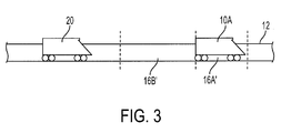
- FIG. 3 is a diagram of the vehicle control system using pseudo-moving blocks.
-
- The preferred embodiment of the present invention will now be discussed. While a specific configuration for the present invention is discussed below, i.e., a rail guided train system, it should be understood that this is done for illustration purposes only. A person skilled in the relevant art will recognize that other components and configurations may be used without departing from the spirit and scope of the invention, such as applying the invention to other vehicles such as trams or streetcars. Referring to FIG. 1, the system includes beacon tags 10 disposed along the length of a
track 12, trains 20 that havetags readers 22 andtransmitters 24, and awayside control unit 30 that preferably transmits information to alltrains 20 within an area 14. - The plurality of beacon tags 10 are disposed along a length of the
track 12 for the area 14 consisting of a predetermined number ofblocks 16. Thetag readers 22 located on thetrains 20 solicit information from the beacon tags 10. Thetransmitters 24 then transmit the solicited information, as well as vehicle identification information for thetrain 20, to awayside control unit 30. Thewayside control unit 30 receives the transmitted position information and vehicle identification information from all of the trains within the area 14 and then transmits a single broadcast of information pertaining to each of theblocks 16 of the area 14. This signal is received by all of thetrains 20 within an area, which in turn use only the information about approachingblocks 16. The beacon tags 10 are preferably passive RF transponders which provide information only when asked. For example, when atag reader 22, which can be a transponder transmitter, requests information from thebeacon tag 10, thebeacon tag 10 responds with whatever information it may have stored within itself. The beacon tags 10 are preferably provided every few meters over the entire length of thetrack 12 and are located between therails 12A. Eachbeacon tag 10 has stored within it at least the following information; tag location identifying precisely where, along the track, the tag is physically located; information regarding the distance to the next, adjacent, identification tag; the identification of the next adjacent identification tag; and information relative to thetrack 12 profile. Track profile information includes information about the location and severity of track grades and track curves, as well as information about maximum vehicle density within areas of the track. When atrain 20 travels within a close proximity of abeacon tag 20, atag reader 22 on the train requests the identifying information from the beacon tags 10. - An onboard computer (not shown) then stores and processes the identification information received from all beacon tags 10 and displays the processed information in a formatted fashion on a display monitor (not shown) visible to a train conductor or other personnel onboard the
train 20. This processed information can include, for example, the current train speed and the train's location. The information from the beacon tags 10, as well as information about the train's 20 identity is also transferred to thetransmitter 24, for transmission to thewayside control unit 30. - The
wayside control unit 30 receives information from all of thetrains 20 regarding the identity and position of all trains within the wayside control unit's area 14. Thewayside control unit 30 then processes the information about each train's 20 identity, each train's location, and thetrack 12 profile, as well as stored information about the train's 20 past locations. Using this information, thewayside control unit 30 is able to calculate information about the status of each of theblocks 16 within the area 14. This status information includes information can include, for example, the allowable speed within eachblock 16, information about the closing ofblocks 16, and information about any required track switching. - The
wayside control unit 30 then transmits a single broadcast pertaining to, preferably, all of theblocks 16 within the area 14. The broadcast is received by receivers 28 on each of thetrains 20.Individual trains 20 receive the information about all of theblocks 16 but only utilize the information about theblock 16A in which thetrain 20A is currently located and theblocks 16 that thetrain 20A is approaching. The individual trains 20 then use this information to control their speed, to stop when appropriate, or to perform track switching when appropriate. - When calculating the information, the
wayside control unit 30 uses the information sent from thetrains 20 to determine the locations of thetrains 20 within the area 14, thewayside control unit 30 assigns ablock 16 oftrack 12 behind eachsubject train 20 as closed to prevent accidents and assigns theblocks 16 where a train can safely travel as open. The system can be used for opening or closing blocks 16 in either a fixed block control system or a "pseudo-moving block" control system. In either of these systems, information about the status ofblocks 16 is transmitted to thetrains 20 by thewayside control unit 30. - Referring to FIG. 2, for a fixed block system blocks are static blocks with predetermined sizes. The
block 16A in which asubject train 20A is travelling is said to have a red aspect associated with it. Theblock 16B immediately behind thesubject train 20A, equal in distance to the length oftrack 12 it would take for thesubject train 20A to safely come to a complete stop, given its present speed, is said to have a yellow aspect, and the block 16C immediately behind the "yellow" block is said to have a green aspect. - Referring to FIG. 3, because in this system the speed of each
train 20 and the profile of thetrack 12 are known, it is possible to provide what is called a pseudo-moving block. In a pseudo-moving block system, theblock 16A' associated with eachtrain 20A moves. The space occupied by atrain 20 at any given moment is that train'sblock 16A', regardless of the train's 20A movement. Theblock 16A moves along with thetrain 20A, unlike a "fixed" block system in which eachblock 16 is distinct from anytrain 20 that happens to be traveling within its boundaries. Further, because the profile of thetrack 12 and other factors, such as weather conditions, the location and speed of othernearby trains 20, the size theblocks 16 near theblock 16A in which eachtrain 20A is traveling is dynamic. - For example, as a
train 20A located on thetracks 12 somewhere behind another slow movingtrain 20 begins to speed up, relative to the slow movingtrain 20, the "red"pseudo block 16B' immediately behind the slow moving train may increase in size, allowing for a greater stopping distance associated with the train that is speeding up. Also, with respect to track profile, if it is known that a sharp curve, requiring severely reduced speeds in order to safely traverse, is approaching relative to a given train, the length and aspects of the blocks behind that train can be adjusted to accommodate for the anticipated reduction in speed of the train. - In addition,
dynamic tags 40 located at positions along the length of the area 14A can be used as a backup system for providing information that is similar to the information provided by thewayside control unit 30. Unlike the beacon tags 10, thedynamic tags 40 does not need to be solicited in order to transfer the data stored within it. For example, adynamic tag 40 can be controlled to transmit certain data to atrain 20, whenever thetag reader 22 or its corresponding antenna, is close enough to thedynamic tag 40. Dynamic tags 40, like the beacon tags 10, are located along the entire length of thetrack 12; however, dynamic tags do not need to be located as close together as the beacon tags 10. - It is of course understood that departures can be made from the preferred embodiment of the invention by those of ordinary skill in the art without departing from the spirit and scope of the invention that is limited only by the following claims.
Claims (24)
- A vehicle control system, comprising:a wayside control unit;a plurality of beacon tags, each beacon tag providing information pertaining to its location, wherein the beacon tags are disposed along a length of a track for a predetermined number of blocks;a tag reader disposed on each of a plurality of vehicles that solicits the information from the beacon tag;a transmitter disposed on each of the vehicles that transmits the solicited information from the beacon tags and vehicle identification information for the respective vehicles to the wayside control unit, wherein the wayside control unit receives the information transmitted by the transmitter and transmits a single broadcast of information pertaining to each of the blocks of the predetermined number of blocks to all of the plurality of vehicles; anda receiver disposed on each of the vehicles that receives the single broadcast.
- The vehicle control system of claim 1, further comprising dynamic tags located at positions along the length of the predetermine number of blocks, wherein the dynamic tags transmit a single broadcast of information pertaining to all of the blocks within the predetermined number of blocks.
- The vehicle control system of claim 1, wherein the single broadcast includes at least one of information about allowable speed within each block, information about the closing of blocks, and information about track switching.
- The vehicle control system of claim 1, wherein the single broadcast is a repetitive signal.
- The vehicle control system of claim 1, wherein each beacon tags further provides information about the identity and position of the next beacon tag.
- The vehicle control system of claim 1, wherein the beacon tags also provide track profile information including at least one of track grade, track curve, or maximum allowable speed.
- The vehicle control system of claim 1, wherein the blocks are fixed blocks.
- The vehicle control system of claim 1, wherein the blocks are pseudo-blocks.
- The vehicle control system of claim 1, wherein each of the plurality of beacon tags is an RF tag separated from an adjacent beacon tag by a few meters.
- The vehicle control system of claim 2, wherein the single broadcast includes at least one of information about allowable speed within each block, information about the closing of blocks, and information about track switching.
- The vehicle control system of claim 2, wherein the single broadcast is a repetitive signal.
- The vehicle control system of claim 2, wherein each beacon tag further provides information about the identity and position of the next beacon tag.
- The vehicle control system of claim 2, wherein each beacon tag also provides track profile information including at least one of track grade, track curve, or maximum allowable speed.
- The vehicle control system of claim 2, wherein the blocks are fixed blocks.
- The vehicle control system of claim 2, wherein the blocks are pseudo-moving blocks.
- The vehicle control system of claim 1, wherein each of the plurality of beacon tags is an RF tag separated from an adjacent beacon tag by a few meters.
- A method of controlling vehicles, comprising:providing information pertaining to the location of one of a plurality of beacon tags to vehicles passing the one of the plurality of beacon tags, wherein the beacon tags are disposed along a length of a track for a predetermined number of blocks;transmitting the information pertaining to the location of the one of the plurality of beacon tags and vehicle identification information for the respective vehicle to a wayside control unit; andtransmitting position information and vehicle identification information from a wayside control unit using a single broadcast of information pertaining to each of the blocks within the predetermined number of blocks to all of the plurality of vehicles.
- The method of controlling vehicles of claim 17, further comprising transmitting a single broadcast of information pertaining to all of the blocks within the predetermined number of blocks from dynamic tags located at positions along the length of the predetermine number of blocks.
- The method of controlling vehicles of claim 17, wherein the single broadcast includes at least one of information about allowable speed within each block, information about the closing of blocks, and information about track switching.
- The method of controlling vehicles of claim 17, wherein the single broadcast is a repetitive signal.
- The method of controlling vehicles of claim 17, further comprising providing information about the identity and position of the next beacon tag.
- The method of controlling vehicles of claim 17, further comprising providing track profile information including at least one of track grade, track curve, or maximum allowable speed from the beacon tags.
- The method of controlling vehicles of claim 17, wherein the blocks are fixed blocks.
- The method of controlling vehicles of claim 17, wherein the blocks are pseudo-moving blocks.
Applications Claiming Priority (2)
| Application Number | Priority Date | Filing Date | Title |
|---|---|---|---|
| US157859 | 1998-09-21 | ||
| US10/157,859 US6666411B1 (en) | 2002-05-31 | 2002-05-31 | Communications-based vehicle control system and method |
Publications (2)
| Publication Number | Publication Date |
|---|---|
| EP1366967A2 true EP1366967A2 (en) | 2003-12-03 |
| EP1366967A3 EP1366967A3 (en) | 2004-01-14 |
Family
ID=29419657
Family Applications (1)
| Application Number | Title | Priority Date | Filing Date |
|---|---|---|---|
| EP03400029A Ceased EP1366967A3 (en) | 2002-05-31 | 2003-05-16 | Communications-based vehicle control system and method |
Country Status (3)
| Country | Link |
|---|---|
| US (1) | US6666411B1 (en) |
| EP (1) | EP1366967A3 (en) |
| CN (1) | CN1461719A (en) |
Cited By (6)
| Publication number | Priority date | Publication date | Assignee | Title |
|---|---|---|---|---|
| WO2009003837A1 (en) | 2007-06-29 | 2009-01-08 | Siemens Aktiengesellschaft | Method and arrangement for the operation of a railroad line |
| CN102244897A (en) * | 2011-08-29 | 2011-11-16 | 南车南京浦镇车辆有限公司 | Method for locating subway train based on RSSI (Received Signal Strength Indicator) |
| CN106672020B (en) * | 2016-12-12 | 2019-04-16 | 交控科技股份有限公司 | Front truck recognition methods, Vehicle Controller and train based on object controller |
| CN115465338A (en) * | 2022-09-20 | 2022-12-13 | 上海富欣智能交通控制有限公司 | Method for dynamically selecting administrator and control system |
| US20230007902A1 (en) * | 2021-07-08 | 2023-01-12 | Transportation Ip Holdings, Llc | Vehicle brake control system and method |
| US11993299B2 (en) * | 2021-07-08 | 2024-05-28 | Transportation Ip Holdings, Llc | Vehicle brake control system and method |
Families Citing this family (42)
| Publication number | Priority date | Publication date | Assignee | Title |
|---|---|---|---|---|
| US20040172175A1 (en) * | 2003-02-27 | 2004-09-02 | Julich Paul M. | System and method for dispatching by exception |
| DE50308942D1 (en) * | 2002-10-30 | 2008-02-14 | Duerr Systems Gmbh | TRUCKED TRANSPORT SYSTEM AND METHOD FOR CONTROLLING VEHICLES OF A TRACKED TRANSPORT SYSTEM |
| US10894550B2 (en) * | 2017-05-05 | 2021-01-19 | Bnsf Railway Company | Railroad virtual track block system |
| JP2004203258A (en) * | 2002-12-26 | 2004-07-22 | Hitachi Ltd | Signal protection method, signal protection device and signal protection system using the same |
| US7092815B2 (en) | 2003-12-17 | 2006-08-15 | Vrbia, Inc. | Traffic control systems for vehicle spacing to dissipate traffic gridlock |
| JP4087786B2 (en) * | 2003-12-19 | 2008-05-21 | 株式会社日立製作所 | Train position detection method |
| JP4454303B2 (en) * | 2003-12-22 | 2010-04-21 | 株式会社日立製作所 | Signal security system |
| ITTO20040325A1 (en) * | 2004-05-14 | 2004-08-14 | Ansaldo Segnalamento Ferroviario Spa | DEVICE FOR THE SAFE TRANSMISSION OF DATA TO BOE FOR RAILWAY SIGNALING |
| CN1817710B (en) * | 2005-02-07 | 2012-10-24 | 傅庆斌 | Method and system for controlling vehicle track running |
| JP4375253B2 (en) * | 2005-02-25 | 2009-12-02 | 株式会社日立製作所 | Signal security system |
| US7469767B2 (en) * | 2005-08-03 | 2008-12-30 | Jasem Al Jasem | Speed control method and system for a motor vehicle |
| US7548032B2 (en) * | 2005-08-23 | 2009-06-16 | General Electric Company | Locomotive speed determination |
| CN101244723B (en) * | 2008-01-25 | 2010-12-22 | 深圳市丰泰瑞达实业有限公司 | Method and device for summarized information transmission of railway operation |
| CN101224752B (en) * | 2008-01-25 | 2012-02-15 | 深圳市丰泰瑞达实业有限公司 | Railway interval kilometer post amending method and device thereof |
| US8452466B2 (en) * | 2008-05-07 | 2013-05-28 | General Electric Company | Methods and system for detecting railway vacancy |
| DE102008060188A1 (en) * | 2008-11-28 | 2010-06-10 | Siemens Aktiengesellschaft | Method and device for distance measurement |
| US9308926B2 (en) * | 2008-12-29 | 2016-04-12 | Universal City Studios Llc | Position control system |
| GB0909373D0 (en) * | 2009-05-30 | 2009-07-15 | Park Signalling Ltd | Apparatus and method for implementing safe visual information provision |
| DE102009039701A1 (en) * | 2009-08-31 | 2011-03-17 | Siemens Aktiengesellschaft | Method for transmitting data from a track-side device to a vehicle and vehicle-side and track-side device |
| CN101713821A (en) * | 2009-11-23 | 2010-05-26 | 北京大成通号轨道交通设备有限公司 | Loop beacon for detecting passing of trains |
| US8428798B2 (en) | 2010-01-08 | 2013-04-23 | Wabtec Holding Corp. | Short headway communications based train control system |
| CN103260994A (en) * | 2010-12-09 | 2013-08-21 | 西门子公司 | Method for communicating information between an on-board control unit and a public transport network |
| US9085310B2 (en) * | 2011-05-25 | 2015-07-21 | Thales Canada Inc. | Method of determining the position of a vehicle moving along a guideway |
| WO2013112885A2 (en) * | 2012-01-25 | 2013-08-01 | Carnegie Mellon University | Railway transport management |
| JP6075839B2 (en) * | 2012-09-20 | 2017-02-08 | 株式会社日立国際電気 | Method for selecting received message in train radio communication system |
| DE102012217470A1 (en) * | 2012-09-26 | 2014-03-27 | Siemens Aktiengesellschaft | A method for generating a driveway setting initiation signal for a central train steering and means on a train for generating the driveline setting initiation signal |
| CN102975748B (en) * | 2012-11-29 | 2015-05-27 | 北京全路通信信号研究设计院有限公司 | Train positioning and speed measuring method and system |
| US11814088B2 (en) | 2013-09-03 | 2023-11-14 | Metrom Rail, Llc | Vehicle host interface module (vHIM) based braking solutions |
| US9499185B2 (en) | 2013-12-20 | 2016-11-22 | Thales Canada Inc | Wayside guideway vehicle detection and switch deadlocking system with a multimodal guideway vehicle sensor |
| FR3019676B1 (en) * | 2014-04-02 | 2017-09-01 | Alstom Transp Tech | METHOD FOR CALCULATING A POSITIONS INTERVAL OF A RAILWAY VEHICLE ON A RAILWAY AND ASSOCIATED DEVICE |
| DE102015203476A1 (en) * | 2015-02-26 | 2016-09-01 | Siemens Aktiengesellschaft | Method and locating device for determining the position of a track-guided vehicle, in particular of a rail vehicle |
| EP3184400A1 (en) * | 2015-12-22 | 2017-06-28 | Televic Rail NV | System and method for providing information to an information system in a vehicle |
| CN106197397B (en) * | 2016-07-15 | 2019-03-29 | 湖南云辙科技有限公司 | One kind is based on guide rail positioning guidance system and method |
| US11465660B2 (en) | 2017-02-28 | 2022-10-11 | Thales Canada Inc. | Apparatuses, systems, methods, and software for train control and tracking using multi sensors, SSD/QR signs, and/or RF reflectors |
| US11511779B2 (en) | 2017-05-05 | 2022-11-29 | Bnsf Railway Company | System and method for virtual block stick circuits |
| US11349589B2 (en) | 2017-08-04 | 2022-05-31 | Metrom Rail, Llc | Methods and systems for decentralized rail signaling and positive train control |
| US11153077B2 (en) * | 2018-12-14 | 2021-10-19 | Westinghouse Air Brake Technologies Corporation | Secure vehicle to vehicle communication |
| CN109664916B (en) * | 2017-10-17 | 2021-04-27 | 交控科技股份有限公司 | Train operation control system with vehicle-mounted controller as core |
| CN109774748B (en) * | 2017-11-14 | 2021-04-27 | 交控科技股份有限公司 | Train overspeed protection method based on vehicle-to-vehicle communication, vehicle-mounted controller and train |
| US11794796B2 (en) * | 2018-05-08 | 2023-10-24 | TekTracking, LLC | System and method to ensure signal light integrity and viewability |
| CN109278808B (en) * | 2018-08-13 | 2021-01-26 | 浙江众合科技股份有限公司 | Multi-protection-zone protection method suitable for American dynamic beacon |
| CN109603167A (en) * | 2018-12-26 | 2019-04-12 | 上海恒润文化集团有限公司 | A kind of rail recreational vehicle anti-collision system |
Citations (3)
| Publication number | Priority date | Publication date | Assignee | Title |
|---|---|---|---|---|
| EP0240051A1 (en) * | 1986-03-07 | 1987-10-07 | Koninklijke KPN N.V. | Radio communication system provided with beacon transmitters |
| US5437422A (en) * | 1992-02-11 | 1995-08-01 | Westinghouse Brake And Signal Holdings Limited | Railway signalling system |
| US6275773B1 (en) * | 1993-08-11 | 2001-08-14 | Jerome H. Lemelson | GPS vehicle collision avoidance warning and control system and method |
Family Cites Families (13)
| Publication number | Priority date | Publication date | Assignee | Title |
|---|---|---|---|---|
| US5006847A (en) | 1984-11-16 | 1991-04-09 | Aeg Westinghouse Transportation Systems, Inc. | Train motion detection apparatus |
| US4864306A (en) | 1986-06-23 | 1989-09-05 | Wiita Floyd L | Railway anticollision apparatus and method |
| GB8620002D0 (en) | 1986-08-16 | 1986-09-24 | Westinghouse Brake & Signal | Communicating vital control signals |
| GB8718552D0 (en) | 1987-08-05 | 1987-09-09 | British Railways Board | Track to train communications systems |
| GB8810922D0 (en) | 1988-05-09 | 1988-06-15 | Westinghouse Brake & Signal | Railway signalling system |
| US5340062A (en) * | 1992-08-13 | 1994-08-23 | Harmon Industries, Inc. | Train control system integrating dynamic and fixed data |
| SE501095C2 (en) | 1992-08-31 | 1994-11-14 | Carrnovo Ab | Method and apparatus for controlling a number of rolling units in a track plant |
| US5332180A (en) * | 1992-12-28 | 1994-07-26 | Union Switch & Signal Inc. | Traffic control system utilizing on-board vehicle information measurement apparatus |
| US5364047A (en) * | 1993-04-02 | 1994-11-15 | General Railway Signal Corporation | Automatic vehicle control and location system |
| US5533695A (en) * | 1994-08-19 | 1996-07-09 | Harmon Industries, Inc. | Incremental train control system |
| JP3521491B2 (en) | 1994-08-31 | 2004-04-19 | トヨタ自動車株式会社 | Road-to-vehicle communication device |
| TW279960B (en) * | 1994-09-23 | 1996-07-01 | Traffic Object Supervision Systems | |
| US5995881A (en) * | 1997-07-22 | 1999-11-30 | Westinghouse Air Brake Company | Integrated cab signal rail navigation system |
-
2002
- 2002-05-31 US US10/157,859 patent/US6666411B1/en not_active Expired - Fee Related
-
2003
- 2003-04-29 CN CN03130604A patent/CN1461719A/en active Pending
- 2003-05-16 EP EP03400029A patent/EP1366967A3/en not_active Ceased
Patent Citations (3)
| Publication number | Priority date | Publication date | Assignee | Title |
|---|---|---|---|---|
| EP0240051A1 (en) * | 1986-03-07 | 1987-10-07 | Koninklijke KPN N.V. | Radio communication system provided with beacon transmitters |
| US5437422A (en) * | 1992-02-11 | 1995-08-01 | Westinghouse Brake And Signal Holdings Limited | Railway signalling system |
| US6275773B1 (en) * | 1993-08-11 | 2001-08-14 | Jerome H. Lemelson | GPS vehicle collision avoidance warning and control system and method |
Cited By (8)
| Publication number | Priority date | Publication date | Assignee | Title |
|---|---|---|---|---|
| WO2009003837A1 (en) | 2007-06-29 | 2009-01-08 | Siemens Aktiengesellschaft | Method and arrangement for the operation of a railroad line |
| US8428797B2 (en) | 2007-06-29 | 2013-04-23 | Siemens Aktiengesellschaft | Method and arrangement for the operation of a railroad line |
| CN102244897A (en) * | 2011-08-29 | 2011-11-16 | 南车南京浦镇车辆有限公司 | Method for locating subway train based on RSSI (Received Signal Strength Indicator) |
| CN106672020B (en) * | 2016-12-12 | 2019-04-16 | 交控科技股份有限公司 | Front truck recognition methods, Vehicle Controller and train based on object controller |
| US10875559B2 (en) | 2016-12-12 | 2020-12-29 | Traffic Control Technology Co., Ltd | Preceding train identification method based on object controller, vehicle on board controller and train |
| US20230007902A1 (en) * | 2021-07-08 | 2023-01-12 | Transportation Ip Holdings, Llc | Vehicle brake control system and method |
| US11993299B2 (en) * | 2021-07-08 | 2024-05-28 | Transportation Ip Holdings, Llc | Vehicle brake control system and method |
| CN115465338A (en) * | 2022-09-20 | 2022-12-13 | 上海富欣智能交通控制有限公司 | Method for dynamically selecting administrator and control system |
Also Published As
| Publication number | Publication date |
|---|---|
| US20030222180A1 (en) | 2003-12-04 |
| EP1366967A3 (en) | 2004-01-14 |
| CN1461719A (en) | 2003-12-17 |
| US6666411B1 (en) | 2003-12-23 |
Similar Documents
| Publication | Publication Date | Title |
|---|---|---|
| US6666411B1 (en) | Communications-based vehicle control system and method | |
| CN107554556B (en) | Heavy haul railway mobile block system based on wireless communication | |
| CN110356434B (en) | Light-weight train control system based on TAG positioning | |
| US11235789B2 (en) | Train control system and train control method including virtual train stop | |
| US9150229B2 (en) | Systems and method for controlling warnings at vehicle crossings | |
| US5740046A (en) | Method to control in a track traffic system moving units, device for effecting of such control and process for installation of the device | |
| CN103010267B (en) | The Train Detection and Identification equipment of self adaptation obturation, system and method | |
| DE102005042218B4 (en) | Railway collision warning device | |
| MXPA05000100A (en) | Train control system and method. | |
| CN102653279A (en) | Train signal system device and train feasible distance detection method | |
| CN110730742B (en) | Method for operating a rail-bound transport system | |
| US5436631A (en) | System for targeted braking of vehicles | |
| EP0782520B1 (en) | A traffic control system, use of it, and a method of controlling the movement of a mobile unit | |
| CN112339792B (en) | Intelligent personal rapid transportation system based on communication control | |
| KR100511643B1 (en) | Interlock Using Position Information | |
| RU2392133C1 (en) | Method and complex safety system (css) for rolling stock automatic target braking | |
| CN113415318B (en) | Train coupling marshalling auxiliary protection system and protection method | |
| KR20160001852A (en) | ATO signaling system based ETCS | |
| RU2519323C1 (en) | System of train separation | |
| JP4125019B2 (en) | Railway vehicle operation support method and system | |
| EP1355817B1 (en) | Rail system for a rail-mounted vehicle | |
| KR20150143958A (en) | Train Operation apparatus by the station to station blocking and method thereof | |
| RU2519317C1 (en) | System to control train traffic | |
| Kobayashi et al. | ATACS (advanced train administration and communication system) | |
| JPH04135967A (en) | Maintenance vehicle security control method and vehicle tracking method |
Legal Events
| Date | Code | Title | Description |
|---|---|---|---|
| PUAI | Public reference made under article 153(3) epc to a published international application that has entered the european phase |
Free format text: ORIGINAL CODE: 0009012 |
|
| PUAL | Search report despatched |
Free format text: ORIGINAL CODE: 0009013 |
|
| AK | Designated contracting states |
Kind code of ref document: A2 Designated state(s): AT BE BG CH CY CZ DE DK EE ES FI FR GB GR HU IE IT LI LU MC NL PT RO SE SI SK TR |
|
| AX | Request for extension of the european patent |
Extension state: AL LT LV MK |
|
| AK | Designated contracting states |
Kind code of ref document: A3 Designated state(s): AT BE BG CH CY CZ DE DK EE ES FI FR GB GR HU IE IT LI LU MC NL PT RO SE SI SK TR |
|
| AX | Request for extension of the european patent |
Extension state: AL LT LV MK |
|
| 17P | Request for examination filed |
Effective date: 20040225 |
|
| 17Q | First examination report despatched |
Effective date: 20040421 |
|
| AKX | Designation fees paid |
Designated state(s): AT BE BG CH CY CZ DE DK EE ES FI FR GB GR HU IE IT LI LU MC NL PT RO SE SI SK TR |
|
| STAA | Information on the status of an ep patent application or granted ep patent |
Free format text: STATUS: THE APPLICATION HAS BEEN REFUSED |
|
| 18R | Application refused |
Effective date: 20050711 |