EP1366959B1 - Wire harness design support system - Google Patents
Wire harness design support system Download PDFInfo
- Publication number
- EP1366959B1 EP1366959B1 EP03011637A EP03011637A EP1366959B1 EP 1366959 B1 EP1366959 B1 EP 1366959B1 EP 03011637 A EP03011637 A EP 03011637A EP 03011637 A EP03011637 A EP 03011637A EP 1366959 B1 EP1366959 B1 EP 1366959B1
- Authority
- EP
- European Patent Office
- Prior art keywords
- layout
- jig plate
- path
- current
- new
- Prior art date
- Legal status (The legal status is an assumption and is not a legal conclusion. Google has not performed a legal analysis and makes no representation as to the accuracy of the status listed.)
- Expired - Fee Related
Links
Images


Classifications
-
- B—PERFORMING OPERATIONS; TRANSPORTING
- B60—VEHICLES IN GENERAL
- B60R—VEHICLES, VEHICLE FITTINGS, OR VEHICLE PARTS, NOT OTHERWISE PROVIDED FOR
- B60R16/00—Electric or fluid circuits specially adapted for vehicles and not otherwise provided for; Arrangement of elements of electric or fluid circuits specially adapted for vehicles and not otherwise provided for
- B60R16/02—Electric or fluid circuits specially adapted for vehicles and not otherwise provided for; Arrangement of elements of electric or fluid circuits specially adapted for vehicles and not otherwise provided for electric constitutive elements
- B60R16/0207—Wire harnesses
-
- Y—GENERAL TAGGING OF NEW TECHNOLOGICAL DEVELOPMENTS; GENERAL TAGGING OF CROSS-SECTIONAL TECHNOLOGIES SPANNING OVER SEVERAL SECTIONS OF THE IPC; TECHNICAL SUBJECTS COVERED BY FORMER USPC CROSS-REFERENCE ART COLLECTIONS [XRACs] AND DIGESTS
- Y10—TECHNICAL SUBJECTS COVERED BY FORMER USPC
- Y10T—TECHNICAL SUBJECTS COVERED BY FORMER US CLASSIFICATION
- Y10T29/00—Metal working
- Y10T29/53—Means to assemble or disassemble
- Y10T29/5313—Means to assemble electrical device
Definitions
- the present invention relates to a wire harness design support system, particularly relates to a design support system of the path layout and the jig plate layout of a wire harness.
- the design of a wire harness wired in a vehicle is prepared in parallel with the design of the vehicle in which the wire harness is wired.
- a demand for the path layout of a wire harness is made from a manufacturer of a vehicle (merely called a car manufacturer) and a part manufacturer receives the demand and manufactures a wire harness that meets the demand.
- the car manufacturer in a production preparation period, repeatedly reviews the modification of a model and specifications and provides related information to the part manufacturer every time.
- the part manufacturer designs the layout of a j ig plate for manufacturing a wire harness demanded by the car manufacturer in consideration of the current jig plate layout, owned jigs and manufacturing efficiency, it proposes a path layout draft of a manufacturable wire harness according to the jig plate layout to the car manufacturer.
- the car manufacturer reviews the acceptance of the path layout draft and informs the part manufacturer of the result. In the production preparation period, such communication is repeated between the car manufacturer and the part manufacturer.
- the part manufacturer is required to frequently modify the design of a jig plate layout and a path layout draft according to the information of modification from the car manufacturer. Besides, the quantity of documents and drawings related to the modification is also enormous. Under such a situation, the part manufacturer demands enhancing the design efficiency of a jig plate layout and a path layout draft respectively to be frequently modified.
- the invention is made in view of the current situation and the object is to provide a wire harness design support system that suitably corresponds to the frequent modification of design and enhances the design efficiency of a jig plate layout and a path layout draft in accordance with it, a wire harness design support method and a computer readable recording medium storing a program thereof.
- the invention is characterized by having the following arrangement.
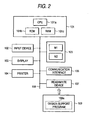
- FIG. 2 is a block diagram showing the configuration of the hardware according to the embodiment.
- the embodiment will be described hereinafter using a part manufacturer that provides a predetermined wire harness to a car manufacturer as an example.
- a design support system basically including a microcomputer 101, an input device 102, a display 103, a printer 104, a storage 105, a communication interface 106 and a read/write memory 107 is used.
- the configuration as hardware of the design support system can be embodied by a well-known desktop computer.
- the microcomputer 101 includes a central processing unit (CPU) 101a, ROM 101b that stores a boot program and RAM 101c that temporarily stores the result of processing.
- the input device 102 is a keyboard and a mouse for inputting each value
- the display 103 is CRT for displaying the result of processing
- the printer 104 is a printer for printing the result of processing.
- the storage 105 corresponds to a path data storing unit (105a) and a jig plate data storing unit (105b) respectively in claims, is actually a hard disk that stores the result of processing and is provided with storage regions M1, M2 respectively described later.
- the communication interface 106 is a modem board for data communication with the car manufacturer using a dedicated line for example.
- the read/write device 107 is a device for reading a design supporting program 109a according to the present invention from a recording medium 109 such as CR-ROM, reading data from a portable record medium on which path layout data and modification information respectively provided from the car manufacturer are stored and writing the layout of a jig plate calculated in the system and a draft of the layout of a path to be proposed to the car manufacturer to the portable record medium for example.
- a recording medium 109 such as CR-ROM
- Each component is connected via an internal bus.
- 18 CPU 101a is activated according to the bootstrap stored in ROM 101b and is operated according to an application program telling a procedure in the embodiment. The procedure in the embodiment and an example of output respectively executed by such a design support system will be described below.
- the microcomputer 101 installs the design supporting program 109a read from the read/write device 109 into, for example, the storage 105. After power on the computer, the microcomputer 101 is activated according to the boot program stored in the ROM 101b and starts the installed design supporting program. According to the design supporting program, the microcomputer 101 designs the path layout and jig plate layout of the wire harness, can output these results on the display device 103 or the printer 104 and can stores these results in the storage 105.
- the design support program 109a is capable of being installed in any personal computer which has the above basic construction, and after installing the program, the computer functions as the design supporting apparatus (it can be called design support system). Further, the design support program 109 is provided not only through the recording medium 109 but also maybe provided though the communication line such as Internet and LAN.
- FIG. 3 is a flowchart showing the basic procedure according to the embodiment executed by the design support system.
- a transition trigger to corresponding processing is on standby.
- control is transferred to the processing corresponding to the transition trigger to the corresponding processing.
- the transition trigger means a button object displayed on the screen of the display 103 for proceeding to the corresponding processing for example.
- a termination instruction is issued, the processing is finished after predetermined processing for termination is executed, however, in case a transition trigger except it is issued, control is transferred to the corresponding processing.
- a path data acquisition process in a step S2 new path data related to the path layout of the wire harness the modification of which is required is acquired.
- the modification includes the change of the position of a connector by the change of a vehicle model on the side of the car manufacturer.Referring to Fig. 4A , this will be described later.
- the new layout data and the current. path data are basically compared and the difference information between both data is detected.
- Information which has an effect upon the current layout of the jig plate and which is calculated based upon the difference information is added to the layout of the jig plate calculated based upon the current path data and it is displayed. Referring to Fig. 4B , this will be described later.
- Fig. 5 shows the basic display example of the embodiment.
- the display examples of the embodiment are displayed on the screen provided by Windows which is an operating system provided by Microsoft for example.
- a path layout 10 is displayed on the upside of the screen of the display 103 and a current jig plate layout 20 is displayed on the downside of the screen. These are displayed on the screen as an image by three-dimensional computer aided design (CAD).
- CAD computer aided design
- the path layout 10 is calculated and displayed based upon three-dimensional positional information included in path data provided by the car manufacturer for example. From the path data, for example, the diameter and the length of the wire harness, the shape and the position of a connector and a clamp as a supporting member connected to the end and the center of the wire harness can be also acquired.
- a trunk 11 wired to a predetermined region of a vehicle, twigs 12; 13 branched from a junction C1 and connectors 12a, 13a are displayed as a wiring image.
- the information 11b, 12b, 13b of each length of the trunk 11 and the twigs 12, 13 can be also displayed together.
- a reference number 11a denotes a reference level.
- the jig plate layout 20 can be also calculated based upon the three-dimensional positional information included in the path data.
- the wire harness is extended on the substantially flat jig plate.
- the wire harness is displayed in a state in which the wire harness is extended on the jig plate and is mounted on jigs 22c, 23c utilized when the wire harness is manufactured as shown in Fig. 5 .
- an angle of each twig 22, 23 branched from a junction C2 with a trunk 21 is different in the jig plate layout 20 from that in the path layout 10.
- each connector 22a, 23a can be moved is displayed by each concentric circle 22d, 23d having the junction C2 in the center.
- the information of the jig plate and a usable jig is stored in the storage 105 beforehand.
- the trunk 21, the twigs 22, 23, a reference level 21a and the connectors 22a, 23a in the jig plate layout 20 correspond to the trunk 11, the twigs 12, 13, the reference level 11 a and the connectors 12a, 13a in the path layout 10.
- the calculated jig plate layout 20 is read and can suitably displayed by storing the calculated jig plate layout in the storage 105 as the current jig plate data.
- the path layout 10 and the jig plate layout 20 shall be displayed in white for example.
- a new jig plate layout calculated based upon the path data acquired in the step S2 is basically output, guide information for guiding a modifiable location calculated based upon the difference information in the new jig plate layout is added to the jig plate layout and it is displayed. Referring to Fig. 4C , this will be described later.
- the jig plate layout is basically suitably modified according to the guide information displayed in the step S4 using the input device 102 and it is displayed. Besides, a path layout draft to which the modification is added is also displayed. Referring to Fig. 4D , this will be described later.
- a path layout draft display process shown in a step S6 a path layout draft in which the information of the material characteristics of the wire harness is added to the result of the modification according to an instruction for manual modification in the step S5 is basically displayed. Besides, the length information of a modified location can be also added. Referring to Fig. 4E , this will be described later.
- step S7 the result acquired in each process shown in the steps S3 to S6 is output on paper by the printer 104, is stored in the storage 105 with a specific file name and is written to a portable record medium via the read/write memory 107.
- a well-known procedure is available for these processing.
- each process shown in the steps S2 to S6 shall be executed by a predetermined transition trigger basically in the order.
- the step S7 can be suitably executed even if each process in the steps S2 to S6 is being executed.
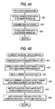
- FIGs. 4A to 4E are flowcharts respectively showing a procedure of each subroutine shown in Fig. 3 .
- Figs. 5 to 11 show output examples acquired in the procedures shown in Fig. 3 .
- jig plate data and path data which can be displayed as the layouts shown in Fig. 5 shall be already stored in the storage 105.
- new path data provided from the car manufacturer for example and related to a path layout the modification of which is required is acquired via the communication interface 106 or the read/write memory 107. At least the three-dimensional positional information of the trunk and the twigs of the wire harness showing a new path layout is included in the path data.
- the current path data in the storage region M1 is transferred to the storage region M2 in a step S21 and new path data acquired in a step S22 is stored in the storage region M1 in a step S23.
- the new path data acquired at this time is stored in the storage region Ml and the path data acquired last time is stored in the storage region M2.
- the step S22 and related hardware correspond to a path data acquiring unit in claims.
- a path layout 10 shown in Fig. 6 is displayed on the display 103 based upon the path data read from the storage region M1, that is, the new path data.
- the display of the path layout 10 is performed as in the method described referring to Fig. 5 .
- the path layout 10 shown in Fig. 6 shows that the position. and the length of the twig 13 shown in Fig. 5 are modified as shown as a twig 13-2.
- the information of the modified length 13b-2 can be simultaneously displayed.
- the similar display to the display in the path layout shown in Fig. 5 is made.
- a current jig plate layout 20 shown in Fig. 6 is displayed based upon the read jig plate data.
- the jig plate layout 20 is similar to the layout shown in Fig. 5 at this time.
- both path data read from the storage regions M1, M2 are compared and the difference information. Between both data is detected. Further, locations that have an effect upon the current jig plate layout 20 are detected based upon the difference information.
- the locations that have the effect are added to the current jig plate layout 20 and it is displayed. That is, as shown in jig plate layout 20 in Fig. 6 , the respective corresponding connector 23a1, jig 23c1 and twig 23-1 are displayed in red for example so that the locations that have the effect can be discriminated from locations except them. Locations that have no effect still remain white for example.
- a concentric circle 23d1 with a junction C2 in the center corresponding to the connector 23a1 is also displayed in red.
- locations to be modified in the current jig plate layout can be easily recognized and the design efficiency of a new jig plate layout is enhanced.
- a trunk name and a twig name are also simultaneously displayed and the information of modification may be also related to the trunk name and the twig name by a character.
- the trunk name and the twig name shall be included in the path data.
- the step S35 and related hardware correspond to a difference information detecting unit in the claims
- the step S36 and related hardware correspond to current jig plate layout output unit in the claims.
- a new jig plate layout 20 shown in Fig. 7 is displayed on the display 103 based upon path data read from the storage region M1, that is, new path data in place of the jig plate layout shown in Fig. 6 .
- the similar processing to that described referring to Fig. 5 is executed.
- the jig plate layout 20 shown in Fig. 7 shows that as a result of changing the position of the connector 23a shown in Fig. 5 , a twig is modified as shown by 23-2.
- a red concentric circle with a junction C2 in the center corresponding to a connector 23a is displayed on the display 103 as a modification guide line 23d2 in place of the concentric circle 23d.
- the modification guide line 23d2 may be also in color except red if the concentric circuit has only to be discriminated from another concentric circle.
- the modification guide line 23d2 shows a range in which the connector 23a the position of which is changed can be moved. Therefore, a new jig plate layout can be easily designed according to the modification guide line 23d2 and the design efficiency is enhanced.
- the step S41 and related hardware correspond to a new jig plate layout output unit in the claims, and the step S42 and related hardware correspond to a modification guide information output unit in the claims.
- the modification guide line 23d2 corresponds to modification guide information.
- a manual modification instruction is issued or not.
- the manual modification instruction can be issued by dragging the connector 23a shown in Fig. 7 to a target point D to be modified using a mouse as the input device 102 for example.
- control is transferred to a step S52 (Y in the step S51).
- the connector 23a is moved to the position of the target point D to be modified according to the modification instruction as shown in Fig. 8 and hereby, the display of the jig and the twig is also modified as shown by 23c3 and 23-3.
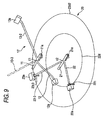
- the modification can be also reflected in the path layout by clicking the button object. That is, in a step S53, a path layout 10' in which the twig 23-3 the position of which is changed as shown by 13-3 in Fig. 9 is added to the path layout 10 shown in Fig.8 and others is displayed.
- the reference number 13-3 denotes the twig after modification and the twig is displayed in yellow for example so that the effect can be discriminated.
- a plan in which the jig plate layout is overlapped with the path layout can be also displayed as shown in Fig. 10 by dragging the jig plate layout.
- the jig plate layout and the path layout are mutually linked and can be displayed in a perspective view shown in Fig.9 or in the plan shown in Fig. 10 .
- Such a manual modification process can be continued until a predetermined manual modification termination trigger is issued by clicking the button obj ect in a step S54 .
- a predetermined manual modification termination trigger is issued by clicking the button obj ect in a step S54 .
- the step S52 shown in Fig. 4D and related hardware correspond to modification unit in Claim
- the step S53 and related hardware correspond to a path layout draft output unit in Claim.
- a path layout draft 10" shown in Fig. 11 is calculated and can be also displayed on the display 103 based upon the material characteristic data of the wire harness estimated based upon the three-dimensional positional information (that is, the thickness and the length of the trunk and the twig) of the trunk and the twig of the wire harness corresponding to a new path layout provided from the car manufacturer in a step S61 (corresponds to Claim 6).
- the material characteristic data is estimated based upon the positional information included in the new path layout. Therefore, a database which relates the shape of typical wire harnesses (corresponding to the positional information) and material characteristics is created by the part manufacturer beforehand by making tests. Approximate material characteristic data is selected based upon positional information included the new path layout provided from the car manufacturer, referring to the database. A twig having a shape shown by 13-2" in Fig. 11 is calculated and displayed using the material characteristic data. At this time, the twig to be an object is made as short as possible. In a step S63, the length information 13b2 can be displayed in the path layout draft 10" acquired as described above in a state in which the length information is added.
- the result acquired as described above is stored on a portable record medium via the read/write memory 107, can be provided to the car manufacturer and can be also provided to the car manufacturer via the communication interface 106.
- the very realistic path layout draft can be provided.
- the car manufacturer to which the path layout draft is provided can also easily grasp positional relation with an interference.
- the step S62 and relatedhardware correspond to a path layout draft output unit in Claim
- the step S63 and related hardware correspond to a length information output unit in the claims.
- the frequent modification of design is precisely processed and the design efficiency of the jig plate layout and the path layout draft in accordance with it can be enhanced.
- the example of the part manufacturer that provides the wire harness to the car manufacturer is. described, however, the invention is not limited to this.
- the invention can be similarly applied.
- the trunk, the twig, the guide line, the design of length information and classification in color respectively shown in relation to the embodiment can be also suitably changed.
- examples variously transformed in a range which does not deviate from the technical idea of the invention are also included in the invention.
- new path data related to a new path layout in which modification is required is acquired, the newpath data and stored current path data are compared and the difference information is detected.
- Information that has an effect upon a current jig plate layout and is calculated based upon the difference information is added to the current jig plate layout and it is output. Therefore, a location to be modified of the current jig plate layout can be easily recognized and the design efficiency of a new jig plate layout is enhanced.
- a new jig plate layout calculated based upon the acquired new path data is output, guide information for guiding a modifiable location calculated based upon the difference information of the new jig plate layout is added to the new jig plate layout and it is output. Therefore, the new jig plate layout can be easily and securely designed based upon the guide information.
- new path data related to a new path layout in which modification is required is acquired, the new path data and stored current path data are compared and the difference information between both data is detected.
- a new jig plate layout calculated based upon the acquired new path data is output.
- Guide information for guiding a modifiable location calculated based upon the difference information of the new jig plate layout is added to the new jig plate layout and it is output. Therefore, the new jib plate layout can be easily designed based upon the guide information and the design efficiency is enhanced.
- new jig plate layout is modified according to an instruction for modifying the new jig. plate layout utilizing guide information
- the review of an optimum jig plate layout is facilitated.
- the realistic layout draft can be acquired.
- the more realistic path layout draft can be acquired.
- a further realistic path layout draft can be provided.
Landscapes
- Engineering & Computer Science (AREA)
- Mechanical Engineering (AREA)
- Management, Administration, Business Operations System, And Electronic Commerce (AREA)
- Electric Cable Installation (AREA)
Description
- The present invention relates to a wire harness design support system, particularly relates to a design support system of the path layout and the jig plate layout of a wire harness.
- The design of a wire harness wired in a vehicle is prepared in parallel with the design of the vehicle in which the wire harness is wired. Normally, a demand for the path layout of a wire harness is made from a manufacturer of a vehicle (merely called a car manufacturer) and a part manufacturer receives the demand and manufactures a wire harness that meets the demand.
- That is, in a production preparation period, the car manufacturer repeatedly reviews the modification of a model and specifications and provides related information to the part manufacturer every time. In the meantime, after the part manufacturer designs the layout of a j ig plate for manufacturing a wire harness demanded by the car manufacturer in consideration of the current jig plate layout, owned jigs and manufacturing efficiency, it proposes a path layout draft of a manufacturable wire harness according to the jig plate layout to the car manufacturer. The car manufacturer reviews the acceptance of the path layout draft and informs the part manufacturer of the result. In the production preparation period, such communication is repeated between the car manufacturer and the part manufacturer.
- Such a wire harness design support system is known from
US 6 845 553 B according to the preamble ofclaim 1. - However, in the determined production preparation period, the part manufacturer is required to frequently modify the design of a jig plate layout and a path layout draft according to the information of modification from the car manufacturer. Besides, the quantity of documents and drawings related to the modification is also enormous. Under such a situation, the part manufacturer demands enhancing the design efficiency of a jig plate layout and a path layout draft respectively to be frequently modified.
- Therefore, the invention is made in view of the current situation and the object is to provide a wire harness design support system that suitably corresponds to the frequent modification of design and enhances the design efficiency of a jig plate layout and a path layout draft in accordance with it, a wire harness design support method and a computer readable recording medium storing a program thereof.
- In order to solve the aforesaid object, the invention is characterized by having the following arrangement.
- Aspect 1 A wire harness design support system for supporting designing a path layout of a wire harness wired in a predetermined location and a jig plate layout for manufacturing the wire harness, comprising:
- a path data storing unit for storing at least current path data related to a current path layout;
- a jig plate data storing unit for storing at least current jig plate data related to a current jig plate layout;
- a path data acquiring unit for acquiring new path data related to a new path layout in which modification is required;
- a difference information detecting unit for comparing the new path data and the current path data and detecting difference information between both data; and
- a current jig plate layout output unit for adding information which is calculated based upon the difference information and has an effect upon the current jig plate layout, to the current jig plate layout calculated based upon the current path data, and outputting the current jig plate layout to which the information is added.
-
Aspect 2 The wire harness design support system according to theaspect 1, further comprising:- a new jig plate layout output unit for outputting a new jig plate layout calculated based upon the new path data; and
- a modification guide information output unit for adding guide information for guiding a modifiable location calculated based upon the difference information, to the new jig plate layout, and outputting the new jig plate layout to which the guide information is added.
- Aspect 3 The wire harness design support system according to the
aspect 2, further comprising:- a modification unit for modifying the new jig plate layout according to an instruction to modify the new jig plate layout utilizing the guide information.
- Aspect 4 The wire harness design support system according to the aspect 3, further comprising:
- a path layout draft output unit for outputting a path layout draft that reflects modification in the new jig plate layout.
-
Aspect 5 The wire harness design support system according to the aspect 4, wherein:- the path layout draft output unit outputs the path layout draft based upon information of material characteristics of a wire harness estimated based upon the new path layout.
- Aspect 6 The wire harness design support system according to the
aspect 5, further comprising:- a length information output unit for adding length information to the path layout draft when length of the wire harness is modified in the new path layout and outputting the path layout drat to which the length information is added.
- Aspect 7 A wire harness design support system for supporting designing a path layout of a wire harness wired in a predetermined location and a jig plate layout for manufacturing the wire harness, comprising:
- a path data storing unit for storing at least current path data related to a current path layout;
- a jig plate data storing unit for storing at least current jig plate data related to a current jig plate layout;
- a path data acquiring unit for acquiring new path data related to a path layout the modification of which is required;
- a difference information detecting unit for comparing the new path data and the current path data and detecting difference information between both data;
- a new jig plate layout output unit for outputting a new jig plate layout calculated based upon the new path data; and
- a modification guide information output unit for adding guide information for guiding a modifiable location calculated based upon the difference information of the new jig plate layout, to the new jig plate layout, and outputting the new jig plate layout to which the guide information is added.
- Aspect 8 The wire harness design support system according to the
aspect 7, further comprising:- a modification unit for modifying the new jig plate layout according to an instruction to modify the new jig plate layout utilizing the guide information.
- Aspect 9 The wire harness design support system according to the aspect 8, further comprising:
- a path layout draft output unit for outputting a path layout draft that reflects modification in the new jig plate layout.
-
Aspect 10 The wire harness design support system according to the aspect 9, wherein:- the path layout draft output unit outputs a path layout draft based upon information of the material characteristics of a wire harness estimated based upon the new path layout.
-
Aspect 11 The wire harness design support system according to theaspect 10, further comprising:- a length information output unit for adding length information to the path layout draft when length of the wire harness is modified in the new path layout, and outputting the new path layout draft to which the length information is added.
- Aspect 12 A method of supporting designing a path layout of a wire harness wired in a predetermined location and a jig plate layout for manufacturing the wire harness, comprising the steps of:
- a path data storing step of storing at least current path data related to a current path layout;
- a jig plate data storing step of storing at least current jig plate data related to a current jig plate layout;
- a path data acquiring step of acquiring new path data related to a new path layout in which modification is required;
- a difference information detecting step of comparing the new path data and the current path data and detecting difference information between both data; and
- a current jig plate layout output step of adding information which is calculated based upon the difference information and has an effect upon the current jig plate layout, to the current j ig plate layout calculated based upon the current path data, and outputting the current jig plate layout to which the information is added.
- Aspect 13 A computer readable recording medium storing a program for supporting designing a path layout of a wire harness wired in a predetermined location and a jig plate layout for manufacturing the wire harness, the program causing a computer to execute the steps of:
- a path data storing step of storing at least current path data related to a current path layout;
- a jig plate data storing step of storing at least current jig plate data related to a current jig plate layout;
- a path data acquiring step of acquiring new path data related to a new path layout in which modification is required;
- a difference information detecting step of comparing the new path data and the current path data and detecting difference information between both data; and
- a current jig plate layout output step of adding information which is calculated based upon. the difference information and has an effect upon the current jig plate layout, to the current jig plate layout calculated based upon the current path data, and outputting the current jig plate layout to which the information is added.
-
-
Fig. 1 is a block diagram showing the basic configuration of a wire harness design support system according to the invention; -
Fig. 2 is a block diagram showing hardware configuration according to the embodiment; -
Fig. 3 is a flowchart showing a basic procedure in the embodiment; -
Figs. 4A to 4E are flowcharts showing a procedure of each subroutine shown inFig. 3 ; -
Fig. 5 shows a basic display example in the embodiment; -
Fig. 6 shows a display example related to a current jig plate layout display process; -
Fig. 7 shows a display example related to a modification guide line display process; -
Fig. 8 shows a display example related to a manual modification process; -
Fig. 9 shows a display example related to the manual modification process; -
Fig. 10 shows a display example related to the manual modification process; and -
Fig. 11 shows a display example related to a path layout draft display process. - Referring to the drawings, an embodiment according to the invention will be described below.
- First, the configuration of hardware according to the embodiment will be described.
Fig. 2 is a block diagram showing the configuration of the hardware according to the embodiment. The embodiment will be described hereinafter using a part manufacturer that provides a predetermined wire harness to a car manufacturer as an example. - As shown in
Fig. 2 , in the embodiment, a design support system basically including amicrocomputer 101, aninput device 102, adisplay 103, aprinter 104, astorage 105, acommunication interface 106 and a read/write memory 107 is used. The configuration as hardware of the design support system can be embodied by a well-known desktop computer. Themicrocomputer 101 includes a central processing unit (CPU) 101a,ROM 101b that stores a boot program andRAM 101c that temporarily stores the result of processing. Theinput device 102 is a keyboard and a mouse for inputting each value, thedisplay 103 is CRT for displaying the result of processing and theprinter 104 is a printer for printing the result of processing. Thestorage 105 corresponds to a path data storing unit (105a) and a jig plate data storing unit (105b) respectively in claims, is actually a hard disk that stores the result of processing and is provided with storage regions M1, M2 respectively described later. Thecommunication interface 106 is a modem board for data communication with the car manufacturer using a dedicated line for example. The read/write device 107 is a device for reading adesign supporting program 109a according to the present invention from arecording medium 109 such as CR-ROM, reading data from a portable record medium on which path layout data and modification information respectively provided from the car manufacturer are stored and writing the layout of a jig plate calculated in the system and a draft of the layout of a path to be proposed to the car manufacturer to the portable record medium for example. Each component is connected via an internal bus. 18CPU 101a is activated according to the bootstrap stored inROM 101b and is operated according to an application program telling a procedure in the embodiment. The procedure in the embodiment and an example of output respectively executed by such a design support system will be described below. - The
microcomputer 101 installs thedesign supporting program 109a read from the read/write device 109 into, for example, thestorage 105. After power on the computer, themicrocomputer 101 is activated according to the boot program stored in theROM 101b and starts the installed design supporting program. According to the design supporting program, themicrocomputer 101 designs the path layout and jig plate layout of the wire harness, can output these results on thedisplay device 103 or theprinter 104 and can stores these results in thestorage 105. Thedesign support program 109a is capable of being installed in any personal computer which has the above basic construction, and after installing the program, the computer functions as the design supporting apparatus (it can be called design support system). Further, thedesign support program 109 is provided not only through therecording medium 109 but also maybe provided though the communication line such as Internet and LAN. - Referring to
Fig. 3 , the basic procedure related to the embodiment will be first described below.Fig. 3 is a flowchart showing the basic procedure according to the embodiment executed by the design support system. - After a power source of this system is turned on, predetermined initialization is finished and an initial screen is displayed, a transition trigger to corresponding processing is on standby. In a step S1 in
Fig. 3 , control is transferred to the processing corresponding to the transition trigger to the corresponding processing. The transition trigger means a button object displayed on the screen of thedisplay 103 for proceeding to the corresponding processing for example. In case a termination instruction is issued, the processing is finished after predetermined processing for termination is executed, however, in case a transition trigger except it is issued, control is transferred to the corresponding processing. - In a path data acquisition process in a step S2, new path data related to the path layout of the wire harness the modification of which is required is acquired. The modification includes the change of the position of a connector by the change of a vehicle model on the side of the car manufacturer.Referring to
Fig. 4A , this will be described later. - In a process for displaying the current layout of the jig plate shown in a step S3, the new layout data and the current. path data are basically compared and the difference information between both data is detected. Information which has an effect upon the current layout of the jig plate and which is calculated based upon the difference information is added to the layout of the jig plate calculated based upon the current path data and it is displayed. Referring to
Fig. 4B , this will be described later. - Referring to
Fig. 5 , a basic display example of the embodiment will be described below.Fig. 5 shows the basic display example of the embodiment. The display examples of the embodiment are displayed on the screen provided by Windows which is an operating system provided by Microsoft for example. As shown inFig. 5 , apath layout 10 is displayed on the upside of the screen of thedisplay 103 and a currentjig plate layout 20 is displayed on the downside of the screen. These are displayed on the screen as an image by three-dimensional computer aided design (CAD). - The
path layout 10 is calculated and displayed based upon three-dimensional positional information included in path data provided by the car manufacturer for example. From the path data, for example, the diameter and the length of the wire harness, the shape and the position of a connector and a clamp as a supporting member connected to the end and the center of the wire harness can be also acquired. - As shown in
Fig. 5 , for thepath layout 10, atrunk 11 wired to a predetermined region of a vehicle, twigs 12; 13 branched from a junction C1 andconnectors information trunk 11 and thetwigs reference number 11a denotes a reference level. - In the meantime, the
jig plate layout 20 can be also calculated based upon the three-dimensional positional information included in the path data. However, in this case, it is supposed that the wire harness is extended on the substantially flat jig plate. In the calculatedjig plate layout 20, the wire harness is displayed in a state in which the wire harness is extended on the jig plate and is mounted onjigs Fig. 5 . As clarified when thejig plate layout 20 is compared with thepath layout 10, an angle of eachtwig trunk 21 is different in thejig plate layout 20 from that in thepath layout 10. Further, a range in which eachconnector concentric circle storage 105 beforehand. - The
trunk 21, thetwigs reference level 21a and theconnectors jig plate layout 20 correspond to thetrunk 11, thetwigs reference level 11 a and theconnectors path layout 10. The calculatedjig plate layout 20 is read and can suitably displayed by storing the calculated jig plate layout in thestorage 105 as the current jig plate data. Thepath layout 10 and thejig plate layout 20 shall be displayed in white for example. - In a modification guide line display process shown in a step S4, a new jig plate layout calculated based upon the path data acquired in the step S2 is basically output, guide information for guiding a modifiable location calculated based upon the difference information in the new jig plate layout is added to the jig plate layout and it is displayed. Referring to
Fig. 4C , this will be described later. - In a manual modification process shown in a step S5, the jig plate layout is basically suitably modified according to the guide information displayed in the step S4 using the
input device 102 and it is displayed. Besides, a path layout draft to which the modification is added is also displayed. Referring toFig. 4D , this will be described later. - In a path layout draft display process shown in a step S6, a path layout draft in which the information of the material characteristics of the wire harness is added to the result of the modification according to an instruction for manual modification in the step S5 is basically displayed. Besides, the length information of a modified location can be also added. Referring to
Fig. 4E , this will be described later. - In a process for printing and storing shown in a step S7, the result acquired in each process shown in the steps S3 to S6 is output on paper by the
printer 104, is stored in thestorage 105 with a specific file name and is written to a portable record medium via the read/write memory 107. For these processing, a well-known procedure is available. - In the embodiment, each process shown in the steps S2 to S6 shall be executed by a predetermined transition trigger basically in the order. However, the step S7 can be suitably executed even if each process in the steps S2 to S6 is being executed.
- Next, referring to
Figs. 4 to 11 , a procedure of each subroutine shown inFig. 3 and display examples acquired in the process will be described.Figs. 4A to 4E are flowcharts respectively showing a procedure of each subroutine shown inFig. 3 .Figs. 5 to 11 show output examples acquired in the procedures shown inFig. 3 . In this case, jig plate data and path data which can be displayed as the layouts shown inFig. 5 shall be already stored in thestorage 105. - In the path data acquisition process shown in
Fig. 4A , new path data provided from the car manufacturer for example and related to a path layout the modification of which is required is acquired via thecommunication interface 106 or the read/write memory 107. At least the three-dimensional positional information of the trunk and the twigs of the wire harness showing a new path layout is included in the path data. To store the path data in the storage region M1 allocated in thestorage 105, the current path data in the storage region M1 is transferred to the storage region M2 in a step S21 and new path data acquired in a step S22 is stored in the storage region M1 in a step S23. As a result, the new path data acquired at this time is stored in the storage region Ml and the path data acquired last time is stored in the storage region M2. The step S22 and related hardware correspond to a path data acquiring unit in claims. - In the current jig plate layout display process shown in
Fig. 4B , first, in a step S31, the path data described above are read from the storage regions Ml, M2. Next, in a step S32, apath layout 10 shown inFig. 6 is displayed on thedisplay 103 based upon the path data read from the storage region M1, that is, the new path data. The display of thepath layout 10 is performed as in the method described referring toFig. 5 . However, thepath layout 10 shown inFig. 6 shows that the position. and the length of thetwig 13 shown inFig. 5 are modified as shown as a twig 13-2. The information of the modifiedlength 13b-2 can be simultaneously displayed. As the other locations are not modified, the similar display to the display in the path layout shown inFig. 5 is made. - Next, in a step S33, the current jig plate data stored in the
storage 105 is read and in a step S34, a currentjig plate layout 20 shown inFig. 6 is displayed based upon the read jig plate data. Thejig plate layout 20 is similar to the layout shown inFig. 5 at this time. - Next, in a step S35, both path data read from the storage regions M1, M2 are compared and the difference information. between both data is detected. Further, locations that have an effect upon the current
jig plate layout 20 are detected based upon the difference information. In a step S36, the locations that have the effect are added to the currentjig plate layout 20 and it is displayed. That is, as shown injig plate layout 20 inFig. 6 , the respective corresponding connector 23a1, jig 23c1 and twig 23-1 are displayed in red for example so that the locations that have the effect can be discriminated from locations except them. Locations that have no effect still remain white for example. A concentric circle 23d1 with a junction C2 in the center corresponding to the connector 23a1 is also displayed in red. Hereby, locations to be modified in the current jig plate layout can be easily recognized and the design efficiency of a new jig plate layout is enhanced. A trunk name and a twig name are also simultaneously displayed and the information of modification may be also related to the trunk name and the twig name by a character. In this case, the trunk name and the twig name shall be included in the path data. Hereby, even if a new path layout provided from the car manufacturer includes no twig, the correspondence is facilitated. The step S35 and related hardware correspond to a difference information detecting unit in the claims, and the step S36 and related hardware correspond to current jig plate layout output unit in the claims. - In the modification guide line display process shown in
Fig. 4C , first, in a step S41, a newjig plate layout 20 shown inFig. 7 is displayed on thedisplay 103 based upon path data read from the storage region M1, that is, new path data in place of the jig plate layout shown inFig. 6 . When the newjig plate layout 20 is displayed, the similar processing to that described referring toFig. 5 is executed. Thejig plate layout 20 shown inFig. 7 shows that as a result of changing the position of theconnector 23a shown inFig. 5 , a twig is modified as shown by 23-2. - Next, in a step S42, a red concentric circle with a junction C2 in the center corresponding to a
connector 23a is displayed on thedisplay 103 as a modification guide line 23d2 in place of theconcentric circle 23d. The modification guide line 23d2 may be also in color except red if the concentric circuit has only to be discriminated from another concentric circle. The modification guide line 23d2 shows a range in which theconnector 23a the position of which is changed can be moved. Therefore, a new jig plate layout can be easily designed according to the modification guide line 23d2 and the design efficiency is enhanced. The step S41 and related hardware correspond to a new jig plate layout output unit in the claims, and the step S42 and related hardware correspond to a modification guide information output unit in the claims. The modification guide line 23d2 corresponds to modification guide information. - In the manual modification process shown inFig. AD, in a step S51, it is inquired whether a manual modification instruction is issued or not. The manual modification instruction can be issued by dragging the
connector 23a shown inFig. 7 to a target point D to be modified using a mouse as theinput device 102 for example. When the manual modification instruction is issued, control is transferred to a step S52 (Y in the step S51). - In the step S52/ the
connector 23a is moved to the position of the target point D to be modified according to the modification instruction as shown inFig. 8 and hereby, the display of the jig and the twig is also modified as shown by 23c3 and 23-3. The modification can be also reflected in the path layout by clicking the button object. That is, in a step S53, a path layout 10' in which the twig 23-3 the position of which is changed as shown by 13-3 inFig. 9 is added to thepath layout 10 shown inFig.8 and others is displayed. The reference number 13-3 denotes the twig after modification and the twig is displayed in yellow for example so that the effect can be discriminated. Further, a plan in which the jig plate layout is overlapped with the path layout can be also displayed as shown inFig. 10 by dragging the jig plate layout. Hereby, the review and the adjustment of an angle of the twig with the trunk are facilitated. The jig plate layout and the path layout are mutually linked and can be displayed in a perspective view shown inFig.9 or in the plan shown inFig. 10 . - Such a manual modification process can be continued until a predetermined manual modification termination trigger is issued by clicking the button obj ect in a step S54 . As described above, as the jig plate layout can be modified by manual operation, the review of an optimum jig plate layout is facilitated. The step S52 shown in
Fig. 4D and related hardware correspond to modification unit in Claim, and the step S53 and related hardware correspond to a path layout draft output unit in Claim. - In the path layout draft display process shown in
Fig. 4E , in a step. S62, apath layout draft 10" shown inFig. 11 is calculated and can be also displayed on thedisplay 103 based upon the material characteristic data of the wire harness estimated based upon the three-dimensional positional information (that is, the thickness and the length of the trunk and the twig) of the trunk and the twig of the wire harness corresponding to a new path layout provided from the car manufacturer in a step S61 (corresponds to Claim 6). - Detailedly, when a twig 13-2" is required to be branched in a direction shown in the
jig plate layout 20 inFig. 11 as a result of the manual modification process shown inFig. 4D in consideration of relation with the already existing jigs on the jig plate, the path layout draft that meets both the branched direction and the condition of constraint such as the position and the direction respectively requested of the connector is required to be created. However, as the wire harness includes a power supply line and a control line, it cannot be freely bent. Then, thepath layout draft 10" that also meets the minimum bend radius and the allowable range of elasticity respectively included in the material characteristic data of the wire harness is calculated. At this time, as no material characteristic data is included in a newpath layout provided from the car manufacturer, the material characteristic data is estimated based upon the positional information included in the new path layout. Therefore, a database which relates the shape of typical wire harnesses (corresponding to the positional information) and material characteristics is created by the part manufacturer beforehand by making tests. Approximate material characteristic data is selected based upon positional information included the new path layout provided from the car manufacturer, referring to the database. A twig having a shape shown by 13-2" inFig. 11 is calculated and displayed using the material characteristic data. At this time, the twig to be an object is made as short as possible. In a step S63, the length information 13b2 can be displayed in thepath layout draft 10" acquired as described above in a state in which the length information is added. - The result acquired as described above is stored on a portable record medium via the read/
write memory 107, can be provided to the car manufacturer and can be also provided to the car manufacturer via thecommunication interface 106. - As described above, the very realistic path layout draft can be provided. Besides, the car manufacturer to which the path layout draft is provided can also easily grasp positional relation with an interference. The step S62 and relatedhardware correspond to a path layout draft output unit in Claim, and the step S63 and related hardware correspond to a length information output unit in the claims.
- As described above, according to the embodiment, the frequent modification of design is precisely processed and the design efficiency of the jig plate layout and the path layout draft in accordance with it can be enhanced.
- In the embodiment, the example of the part manufacturer that provides the wire harness to the car manufacturer is. described, however, the invention is not limited to this. For example, even if the part manufacturer in the embodiment is replaced with a department that provides a wire harness to a manufacturing department in the same company, the invention can be similarly applied. Besides, the trunk, the twig, the guide line, the design of length information and classification in color respectively shown in relation to the embodiment can be also suitably changed. In addition, it need scarcely be said that examples variously transformed in a range which does not deviate from the technical idea of the invention are also included in the invention.
- As described above, according to the invention disclosed in Claim l, new path data related to a new path layout in which modification is required is acquired, the newpath data and stored current path data are compared and the difference information is detected. Information that has an effect upon a current jig plate layout and is calculated based upon the difference information is added to the current jig plate layout and it is output. Therefore, a location to be modified of the current jig plate layout can be easily recognized and the design efficiency of a new jig plate layout is enhanced.
- According to the invention, a new jig plate layout calculated based upon the acquired new path data is output, guide information for guiding a modifiable location calculated based upon the difference information of the new jig plate layout is added to the new jig plate layout and it is output. Therefore, the new jig plate layout can be easily and securely designed based upon the guide information.
- According to the inventions, new path data related to a new path layout in which modification is required is acquired, the new path data and stored current path data are compared and the difference information between both data is detected. Besides, a new jig plate layout calculated based upon the acquired new path data is output. Guide information for guiding a modifiable location calculated based upon the difference information of the new jig plate layout is added to the new jig plate layout and it is output. Therefore, the new jib plate layout can be easily designed based upon the guide information and the design efficiency is enhanced.
- According to the invention, as new jig plate layout is modified according to an instruction for modifying the new jig. plate layout utilizing guide information, the review of an optimum jig plate layout is facilitated.
- According to the invention, as a path layout draft 10' that reflects modification in a new jig plate layout is also output, the realistic layout draft can be acquired.
- According to the invention, as a
path layout draft 10" based upon information related to the material characteristic of a wire harness estimated based upon the new path layout is output, the more realistic path layout draft can be acquired. - According to the invention, as the length information is added and it is output when the length in a new path layout is modified by a path layout draft, a further realistic path layout draft can be provided.
Claims (13)
- A wire harness design support system for supporting designing a path layout of a wire harness wired in a predetermined location and a jig plate layout for manufacturing the wire harness, comprising:a path data storing unit for storing at least current path data related to a current path layout;a jig plate data storing unit for storing at least current jig plate data related to a current jig plate layout;a path data acquiring unit for acquiring new path data related to a new path layout in which modification is required;characterised bya difference information detecting unit for comparing the new path data and the current path data and detecting difference information between both data; anda current jig plate layout output unit for adding information which is calculated based upon the difference information and has an effect upon the current jig plate layout, to the current jig plate layout calculated based upon the current path data, outputting the current jig plate layout to which the information is added, anda location to be modified of the current jig plate layout is displayed based on the difference information.
- The wire harness design support system according to claim 1, further comprising:a new jig plate layout output unit for outputting a new jig plate layout calculated based upon the new path data; anda modification guide information output unit for adding guide information for guiding a modifiable location calculated based upon the difference information, to the new jig plate layout, and outputting the new jig plate layout to which the guide information is added.
- The wire harness design support system according to claim 2, further comprising:a modification unit for modifying the new jig plate layout according to an instruction to modify the new jig plate layout utilizing the guide information.
- The wire harness design support system according to claim 3, further comprising:a path layout draft output unit for outputting a path layout draft that reflects modification in the new jig plate layout.
- The wire harness design support system according to claim 4, wherein the path layout draft output unit outputs the path layout draft based upon information of material characteristics of a wire harness estimated based upon the new path layout.
- The wire harness design support system according to claim 5, further comprising:a length information output unit for adding length information to the path layout draft when length of the wire harness is modified in the new path layout and outputting the path layout draft to which the length information is added.
- A wire harness design support system for supporting designing a path layout of a wire harness wired in a predetermined location and a jig plate layout for manufacturing the wire harness, comprising:a path data storing unit for storing at least current path data related to a current path layout;a jig plate data storing unit for storing at least current jig plate data related to a current jig plate layout;a path data acquiring unit for acquiring new path data related to a path layout the modification of which is required;characterised bya difference information detecting unit for comparing the new path data and the current path data and detecting difference information between both data;a new jig plate layout output unit for outputting a new jig plate layout calculated based upon the new path data; anda modification guide information output unit for adding guide information for guiding a modifiable location calculated based upon the difference information of the new jig plate layout, to the new jig plate layout, and outputting the new jig plate layout to which the guide information is added;a location to be modified of the current jig plate layout is displayed based on the difference information.
- The wire harness design support system according to claim 7, further comprising:a modification unit for modifying the new jig plate layout according to an instruction to modify the new jig plate layout utilizing the guide information.
- The wire harness design support system according to claim 8, further comprising:a path layout draft output unit for outputting a path layout draft that reflects modification in the new jig plate layout.
- The wire harness design support system according to claim 9, wherein the path layout draft output unit outputs a path layout draft based upon information of the material characteristics of a wire harness estimated based upon the new path layout.
- The wire harness design support system according to claim 10, further comprising:a length information output unit for adding length information to the path layout draft when length of the wire harness is modified in the new path layout, and outputting the new path layout draft to which the length information is added.
- A method of supporting designing a path layout of a wire harness wired in a predetermined location and a jig plate layout for manufacturing the wire harness, comprising the steps of:a path data storing step of storing at least current path data related to a current path layout;a jig plate data storing step of storing at least current jig plate data related to a current jig plate layout;a path data acquiring step of acquiring new path data related to a new path layout in which modification is required;characterised bya difference information detecting step of comparing the new path data and the current path data and detecting difference information between both data; anda current jig plate layout output step of adding information which is calculated based upon the difference information and has an effect upon the current jig plate layout, to the current jig plate layout calculated based upon the current path data, outputting the current jig plate layout to which the information is added, anda location to be modified of the current jig plate layout is displayed based on the difference information.
- A computer readable recording medium storing a program for supporting designing a path layout of a wire harness wired in a predetermined location and a jig plate layout for manufacturing the wire harness, the program causing a computer to execute the steps of:a path data storing step of storing at least current path data related to a current path layout;a jig plate data storing step of storing at least current jig plate data related to a current jig plate layout;a path data acquiring step of acquiring new path data related to a new path layout in which modification is required;characterised bya difference information detecting step of comparing the new path data and the current path data and detecting difference information between both data; anda current jig plate layout output step of adding information which is calculated based upon the difference information and has an effect upon the current jig plate layout, to the current jig plate layout calculated based upon the current path data, outputting the current jig plate layout to which the information is added, anda location to be modified of the current jig plate layout is displayed based on the difference information.
Applications Claiming Priority (2)
| Application Number | Priority Date | Filing Date | Title |
|---|---|---|---|
| JP2002147338 | 2002-05-22 | ||
| JP2002147338 | 2002-05-22 |
Publications (3)
| Publication Number | Publication Date |
|---|---|
| EP1366959A2 EP1366959A2 (en) | 2003-12-03 |
| EP1366959A3 EP1366959A3 (en) | 2004-09-15 |
| EP1366959B1 true EP1366959B1 (en) | 2009-07-15 |
Family
ID=29417122
Family Applications (1)
| Application Number | Title | Priority Date | Filing Date |
|---|---|---|---|
| EP03011637A Expired - Fee Related EP1366959B1 (en) | 2002-05-22 | 2003-05-22 | Wire harness design support system |
Country Status (3)
| Country | Link |
|---|---|
| US (1) | US6898473B2 (en) |
| EP (1) | EP1366959B1 (en) |
| DE (1) | DE60328332D1 (en) |
Families Citing this family (16)
| Publication number | Priority date | Publication date | Assignee | Title |
|---|---|---|---|---|
| JP4996138B2 (en) * | 2006-05-30 | 2012-08-08 | 矢崎総業株式会社 | Wire harness assembly support device, wire harness assembly support unit, and wire harness assembly support method |
| WO2008084534A1 (en) * | 2007-01-10 | 2008-07-17 | Fujitsu Limited | Design support system, method and program |
| US20080301613A1 (en) | 2007-06-01 | 2008-12-04 | Simon Edward Holdsworth | Designing wiring harnesses |
| US7735044B2 (en) * | 2007-06-05 | 2010-06-08 | Simon Edward Holdsworth | Combination of ground devices in wiring harness designs |
| JP5062254B2 (en) * | 2007-06-26 | 2012-10-31 | 富士通株式会社 | Design support apparatus, method and program |
| US8078303B2 (en) | 2007-07-03 | 2011-12-13 | Southwire Company | Electronic supervisor |
| US20090157209A1 (en) * | 2007-12-14 | 2009-06-18 | Simon Edward Holdsworth | Wire option expressions in wiring harness designs |
| AU2011254087B2 (en) * | 2008-02-27 | 2012-08-09 | Yazaki Corporation | Branch angle design support device |
| EP2570949B1 (en) * | 2008-02-27 | 2018-12-12 | Yazaki Corporation | Device for designing a branch angle at a branch point of a wire harness |
| US8706452B2 (en) * | 2008-06-26 | 2014-04-22 | Siemens Product Lifecycle Management Software Inc. | System and method for collision-free CAD design of pipe and tube paths |
| JP5195641B2 (en) * | 2009-05-26 | 2013-05-08 | 富士通株式会社 | Harness verification device and harness verification program |
| JP6195476B2 (en) | 2013-05-31 | 2017-09-13 | 矢崎総業株式会社 | Analysis device, analysis method and program |
| JP6195480B2 (en) | 2013-07-08 | 2017-09-13 | 矢崎総業株式会社 | Analysis device, analysis method, and program |
| US11157868B2 (en) | 2013-11-20 | 2021-10-26 | Home Depot Product Authority, Llc | Systems and methods for identifying substitute goods |
| US10747911B2 (en) * | 2014-12-15 | 2020-08-18 | Mentor Graphics Corporation | Constrained flattening of design data |
| CN104536848B (en) * | 2014-12-22 | 2018-05-08 | 小米科技有限责任公司 | Firmware restoration method, apparatus and terminal |
Family Cites Families (13)
| Publication number | Priority date | Publication date | Assignee | Title |
|---|---|---|---|---|
| GB2087760B (en) * | 1980-11-20 | 1984-10-03 | Yazaki Corp | Producing a wire harness |
| US5168904A (en) * | 1991-10-23 | 1992-12-08 | Electro-Wire Products, Inc. | Reconfigurable wiring harness jig |
| EP0891021B1 (en) * | 1997-07-07 | 2005-11-23 | J.S.T. Mfg. Co., Ltd. | An apparatus for processing information of a wiring harness |
| JP3358154B2 (en) * | 1997-08-27 | 2002-12-16 | 矢崎総業株式会社 | WIRE HARNESS, ITS MANUFACTURING METHOD AND DEVICE |
| JP3672215B2 (en) * | 1998-03-16 | 2005-07-20 | 矢崎総業株式会社 | Wire harness manufacturing system |
| JP2000011778A (en) * | 1998-06-22 | 2000-01-14 | Sumitomo Wiring Syst Ltd | Cutting size setting method for wire-harness wire |
| JP3732664B2 (en) | 1998-11-30 | 2006-01-05 | 矢崎総業株式会社 | Wire harness wiring design apparatus and method |
| JP4164784B2 (en) | 2000-03-02 | 2008-10-15 | マツダ株式会社 | Wire material design support apparatus, wire design support method, and computer-readable storage medium |
| JP2001250438A (en) | 2000-03-02 | 2001-09-14 | Mazda Motor Corp | Apparatus and method for assisting wiring design with wiring bar and computer readable storage medium |
| JP4164785B2 (en) | 2000-03-02 | 2008-10-15 | マツダ株式会社 | Wire material design support apparatus, wire design support method, and computer-readable storage medium |
| DE10029086C2 (en) * | 2000-06-13 | 2002-05-02 | Weber Helga Dr Ing | Procedure for automatically creating a work plan |
| US6842173B2 (en) * | 2001-06-13 | 2005-01-11 | Sumitomo Wiring Systems, Ltd. | Wiring harness designing method, computer program and system |
| JP3845287B2 (en) * | 2001-10-09 | 2006-11-15 | トヨタ自動車株式会社 | Wire harness production preparation system |
-
2003
- 2003-05-22 US US10/442,997 patent/US6898473B2/en not_active Expired - Fee Related
- 2003-05-22 DE DE60328332T patent/DE60328332D1/en not_active Expired - Lifetime
- 2003-05-22 EP EP03011637A patent/EP1366959B1/en not_active Expired - Fee Related
Also Published As
| Publication number | Publication date |
|---|---|
| US6898473B2 (en) | 2005-05-24 |
| DE60328332D1 (en) | 2009-08-27 |
| US20040019399A1 (en) | 2004-01-29 |
| EP1366959A2 (en) | 2003-12-03 |
| EP1366959A3 (en) | 2004-09-15 |
Similar Documents
| Publication | Publication Date | Title |
|---|---|---|
| EP1366959B1 (en) | Wire harness design support system | |
| US6289254B1 (en) | Parts selection apparatus and parts selection system with CAD function | |
| US4870591A (en) | System for ensuring device compatibility | |
| CN100458780C (en) | Layout processing method, layout processing apparatus, and layout processing program | |
| US4939668A (en) | System for designing intercommunications networks | |
| US8413118B2 (en) | Configuration diagram with connections that represent physical couplings between devices | |
| US7367028B2 (en) | Graphically deploying programs on devices in a system | |
| US4985855A (en) | Method for producing installation instructions for three dimensional assemblies | |
| US7831320B2 (en) | Parameter setting device | |
| US5019992A (en) | System for designing intercommunication networks | |
| CN100561435C (en) | Signal conditioning package and information processing method | |
| EP1821253A1 (en) | Parts catalog system, method and program to generate parts catalog and recording medium storing the program | |
| EP1736894A1 (en) | Digitization service manual generation method and additional data generation method | |
| US20050188348A1 (en) | Geometric modeling system with intelligent configuring of solid shapes | |
| US20050119773A1 (en) | Harness design supporting apparatus and method, and computer readable recording medium which stores harness design supporting program therein | |
| US20090326874A1 (en) | Designing support method, designing support equipment, program and computer-readable storage medium | |
| US20100163615A1 (en) | Cabling work aiding system and work aiding method | |
| EP1486899A1 (en) | Parts catalog creating system and program therefor | |
| US8146052B2 (en) | Method and system for hierarchical hardware mapping for software design | |
| US20030189566A1 (en) | Three-dimensional modeling system | |
| US6970078B2 (en) | Methods and apparatus for generating a data structure indicative of an alarm system circuit | |
| CN111176646A (en) | Generation method and device of emergency plan web page | |
| JP4629316B2 (en) | Wire harness design support system and design support program | |
| Omura | Mastering AutoCAD 2000 | |
| US20120072438A1 (en) | Generation and Processing of Pick/Put System Configuration and Recipe Data Sets |
Legal Events
| Date | Code | Title | Description |
|---|---|---|---|
| PUAI | Public reference made under article 153(3) epc to a published international application that has entered the european phase |
Free format text: ORIGINAL CODE: 0009012 |
|
| AK | Designated contracting states |
Kind code of ref document: A2 Designated state(s): AT BE BG CH CY CZ DE DK EE ES FI FR GB GR HU IE IT LI LU MC NL PT RO SE SI SK TR |
|
| AX | Request for extension of the european patent |
Extension state: AL LT LV MK |
|
| PUAL | Search report despatched |
Free format text: ORIGINAL CODE: 0009013 |
|
| AK | Designated contracting states |
Kind code of ref document: A3 Designated state(s): AT BE BG CH CY CZ DE DK EE ES FI FR GB GR HU IE IT LI LU MC NL PT RO SE SI SK TR |
|
| AX | Request for extension of the european patent |
Extension state: AL LT LV MK |
|
| 17P | Request for examination filed |
Effective date: 20050311 |
|
| AKX | Designation fees paid |
Designated state(s): DE FR GB IT SE |
|
| 17Q | First examination report despatched |
Effective date: 20070305 |
|
| RAP1 | Party data changed (applicant data changed or rights of an application transferred) |
Owner name: YAZAKI CORPORATION |
|
| GRAP | Despatch of communication of intention to grant a patent |
Free format text: ORIGINAL CODE: EPIDOSNIGR1 |
|
| GRAS | Grant fee paid |
Free format text: ORIGINAL CODE: EPIDOSNIGR3 |
|
| GRAA | (expected) grant |
Free format text: ORIGINAL CODE: 0009210 |
|
| AK | Designated contracting states |
Kind code of ref document: B1 Designated state(s): DE FR GB IT SE |
|
| REG | Reference to a national code |
Ref country code: GB Ref legal event code: FG4D |
|
| REF | Corresponds to: |
Ref document number: 60328332 Country of ref document: DE Date of ref document: 20090827 Kind code of ref document: P |
|
| REG | Reference to a national code |
Ref country code: SE Ref legal event code: TRGR |
|
| PLBE | No opposition filed within time limit |
Free format text: ORIGINAL CODE: 0009261 |
|
| STAA | Information on the status of an ep patent application or granted ep patent |
Free format text: STATUS: NO OPPOSITION FILED WITHIN TIME LIMIT |
|
| 26N | No opposition filed |
Effective date: 20100416 |
|
| REG | Reference to a national code |
Ref country code: FR Ref legal event code: PLFP Year of fee payment: 14 |
|
| PGFP | Annual fee paid to national office [announced via postgrant information from national office to epo] |
Ref country code: GB Payment date: 20160518 Year of fee payment: 14 Ref country code: DE Payment date: 20160518 Year of fee payment: 14 |
|
| PGFP | Annual fee paid to national office [announced via postgrant information from national office to epo] |
Ref country code: SE Payment date: 20160511 Year of fee payment: 14 Ref country code: FR Payment date: 20160412 Year of fee payment: 14 Ref country code: IT Payment date: 20160524 Year of fee payment: 14 |
|
| REG | Reference to a national code |
Ref country code: DE Ref legal event code: R119 Ref document number: 60328332 Country of ref document: DE |
|
| REG | Reference to a national code |
Ref country code: SE Ref legal event code: EUG |
|
| GBPC | Gb: european patent ceased through non-payment of renewal fee |
Effective date: 20170522 |
|
| PG25 | Lapsed in a contracting state [announced via postgrant information from national office to epo] |
Ref country code: SE Free format text: LAPSE BECAUSE OF NON-PAYMENT OF DUE FEES Effective date: 20170523 |
|
| REG | Reference to a national code |
Ref country code: FR Ref legal event code: ST Effective date: 20180131 |
|
| PG25 | Lapsed in a contracting state [announced via postgrant information from national office to epo] |
Ref country code: DE Free format text: LAPSE BECAUSE OF NON-PAYMENT OF DUE FEES Effective date: 20171201 Ref country code: GB Free format text: LAPSE BECAUSE OF NON-PAYMENT OF DUE FEES Effective date: 20170522 |
|
| PG25 | Lapsed in a contracting state [announced via postgrant information from national office to epo] |
Ref country code: FR Free format text: LAPSE BECAUSE OF NON-PAYMENT OF DUE FEES Effective date: 20170531 Ref country code: IT Free format text: LAPSE BECAUSE OF NON-PAYMENT OF DUE FEES Effective date: 20170522 |