EP1365411A2 - Record medium playback apparatus and record medium playback method - Google Patents
Record medium playback apparatus and record medium playback method Download PDFInfo
- Publication number
- EP1365411A2 EP1365411A2 EP03253119A EP03253119A EP1365411A2 EP 1365411 A2 EP1365411 A2 EP 1365411A2 EP 03253119 A EP03253119 A EP 03253119A EP 03253119 A EP03253119 A EP 03253119A EP 1365411 A2 EP1365411 A2 EP 1365411A2
- Authority
- EP
- European Patent Office
- Prior art keywords
- playback
- program information
- time
- power
- record
- Prior art date
- Legal status (The legal status is an assumption and is not a legal conclusion. Google has not performed a legal analysis and makes no representation as to the accuracy of the status listed.)
- Withdrawn
Links
- 238000000034 method Methods 0.000 title claims description 14
- 230000003287 optical effect Effects 0.000 description 46
- 230000007246 mechanism Effects 0.000 description 5
- 230000006870 function Effects 0.000 description 3
- 238000010586 diagram Methods 0.000 description 2
- 238000012986 modification Methods 0.000 description 2
- 230000004048 modification Effects 0.000 description 2
- 230000008569 process Effects 0.000 description 2
Images

Classifications
-
- G—PHYSICS
- G11—INFORMATION STORAGE
- G11B—INFORMATION STORAGE BASED ON RELATIVE MOVEMENT BETWEEN RECORD CARRIER AND TRANSDUCER
- G11B27/00—Editing; Indexing; Addressing; Timing or synchronising; Monitoring; Measuring tape travel
- G11B27/10—Indexing; Addressing; Timing or synchronising; Measuring tape travel
- G11B27/102—Programmed access in sequence to addressed parts of tracks of operating record carriers
- G11B27/105—Programmed access in sequence to addressed parts of tracks of operating record carriers of operating discs
-
- G—PHYSICS
- G11—INFORMATION STORAGE
- G11B—INFORMATION STORAGE BASED ON RELATIVE MOVEMENT BETWEEN RECORD CARRIER AND TRANSDUCER
- G11B19/00—Driving, starting, stopping record carriers not specifically of filamentary or web form, or of supports therefor; Control thereof; Control of operating function ; Driving both disc and head
- G11B19/02—Control of operating function, e.g. switching from recording to reproducing
-
- G—PHYSICS
- G11—INFORMATION STORAGE
- G11B—INFORMATION STORAGE BASED ON RELATIVE MOVEMENT BETWEEN RECORD CARRIER AND TRANSDUCER
- G11B27/00—Editing; Indexing; Addressing; Timing or synchronising; Monitoring; Measuring tape travel
- G11B27/10—Indexing; Addressing; Timing or synchronising; Measuring tape travel
- G11B27/19—Indexing; Addressing; Timing or synchronising; Measuring tape travel by using information detectable on the record carrier
- G11B27/28—Indexing; Addressing; Timing or synchronising; Measuring tape travel by using information detectable on the record carrier by using information signals recorded by the same method as the main recording
- G11B27/32—Indexing; Addressing; Timing or synchronising; Measuring tape travel by using information detectable on the record carrier by using information signals recorded by the same method as the main recording on separate auxiliary tracks of the same or an auxiliary record carrier
- G11B27/327—Table of contents
- G11B27/329—Table of contents on a disc [VTOC]
-
- G—PHYSICS
- G11—INFORMATION STORAGE
- G11B—INFORMATION STORAGE BASED ON RELATIVE MOVEMENT BETWEEN RECORD CARRIER AND TRANSDUCER
- G11B27/00—Editing; Indexing; Addressing; Timing or synchronising; Monitoring; Measuring tape travel
- G11B27/36—Monitoring, i.e. supervising the progress of recording or reproducing
Definitions
- This invention relates to a playback apparatus and a playback method of a record medium such as a disk.
- a record medium playback apparatus for playing back program information such as music data, recorded on a record medium such as a disk in a related art starts playback simply at the playback position when the power of the playback apparatus is turned on. For example, if the power of the playback apparatus is turned off while program information recorded on a record medium is being played back, and is again turned on, the playback apparatus restarts playback of the program information at the playback position at which the pickup was positioned when the power was turned off.
- playing back the program information is started with the skipped introduction part of the program information or if the program information ends with a fade-out, playing back the program information is started at the fade-out part; the event maybe offensive to the user.
- JP-A-4-037495 can effectively eliminate the condition of "playback with the beginning part skipped" and the condition of "playback with the last part remaining," " however, similar processing is performed regardless of the length of the record time of program information and therefore it is not always preferable method to playback for a user.
- a record medium playback apparatus for playing back a record medium recording a plurality of pieces of program information and information including record time for each of the pieces of program information
- the apparatus having: a playback section adapted to play back the program information; and a playback control section adapted to control a playback start position of the program information when the record medium playback apparatus is restarted after power thereof was turned off, wherein the playback control section determines the playback start position of the program information using a first sequence when the record time of the whole program information corresponding to the playback position at the power off is less than a predetermined time, and determines the playback start position of the program information using a second sequence when the record time of the whole program information corresponding to the playback position at the power off is equal to or longer than the predetermined time.
- a record medium playback method for playing back a record medium recording a plurality of pieces of program information and information including record time for each of the pieces of program information, the method including: when a record medium playback apparatus is restarted after power thereof was turned off, comparing the record time of the whole program information corresponding to the playback position at the power off with a predetermined time; determining a playback start position of program information using a first sequence when the record time is less than the predetermined time; determining a playback start position of program information using a second 'sequence when the record time is equal to or longer than the predetermined time; and starting playing back of the program information at the determined playback start position.
- a record medium playback apparatus for playing back program information recorded on a optical disk will be discussed as an example.
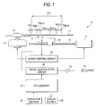
- FIG. 1 is a diagram to show the configuration of an optical disk player 10 of a record medium playback apparatus.
- Six pieces of program information (track numbers TNO. 1 to TNO. 6) are recorded in a data area 11a of an optical disk 11 of a record medium with information such as track numbers and time codes (in hours/minutes/seconds format, for example).
- TOC Table of Contents
- the optical disk player 10 is provided with a turntable 14 on which the optical disk 11 is placed for rotation and a spindle motor 13 for rotating the turntable 14.
- a pickup 15 for applying laser beam to the information record side of the optical disk 11 and reading program information, a feed screw mechanism 18 for allowing the pickup 15 to reciprocate in the radial direction of the optical disk 11, and a carriage motor 17 for rotating the feed screw mechanism 18 are provided below the optical disk 11 placed on the turntable 14.
- the feed screw mechanism 18 is rotated in the positive negative direction by a driving force supplied from the carriage motor 17 for reciprocating the pickup 15 in the radial direction of the optical disk 11.
- the optical disk player 10 is also provided with a servo control circuit 30 for controlling the rotation speed of the spindle motor '13 and the number of revolutions of the carriage motor 17 and a signal demodulation circuit 20 for performing predetermined signal processing such as error correction processing and demodulation processing, for the program information read by the pickup 15.
- a servo control circuit 30 for controlling the rotation speed of the spindle motor '13 and the number of revolutions of the carriage motor 17
- a signal demodulation circuit 20 for performing predetermined signal processing such as error correction processing and demodulation processing, for the program information read by the pickup 15.
- the optical disk player 10 is also provided with an audio output circuit 19 consisting of a D/A converter for converting the program information subjected to the signal processing by the signal demodulation circuit 20 into analog data, an amplifier for amplifying the program information converted into the analog data, a loudspeaker for outputting the amplified program information, and the like.
- a CPU 21 controls the servo control circuit 30 and the signal demodulation circuit 20.
- a display section 23 displays data such as an elapsed time of playback of program information, and the track number.
- An operation section 22 is operated by the user to select the track number to play or to input an operation command to start and stop the playback.
- the optical disk 11 when the optical disk 11 is inserted through a disk slot (not shown) into the main unit of the optical disk player 10, the optical disk 11 is placed on the turntable 14.
- the servo control circuit 30 controls rotating the spindle motor 13 so as to rotate the optical disk 11 at a constant linear speed.
- the servo control circuit 30 controls the carriage motor 17 for driving the feed screw mechanism 18 so as to place laser beam of the pickup 15 at a predetermined position in the read-in area of the optical disk 11.
- the TOC information read by the pickup 15 is subjected to signal processing by the signal demodulation circuit 20 and is stored in memory contained in the CPU 21.
- the servo control circuit 30 also controls the carriage motor 17 for driving the feed screw mechanism 18 so as to place laser beam of the pickup 15 at the beginning position of the program information with track number TNO.1 in the data area.
- the pickup 15 starts to read the program information with track number TNO.1 at the beginning thereof and the read program information is output through the signal demodulation circuit 20 and the audio output circuit 19.
- the CPU 21 receives a signal of the selection operation and controls the servo control circuit 30 so as to place laser beam of the pickup 15 at the top position of the selected track number.
- the servo control circuit 30 controls the carriage motor 17 for placing laser beam of the pickup 15 at a predetermined position.
- the pickup 15 reads the program information with the selected track number and the read program information is output through the signal demodulation circuit 20 and the audio output circuit 19.
- the optical disk player 10 functions as, for example, an in-car disk player installed in a vehicle, it is connected to an ACC line (accessory power line) of the vehicle and is started by a power supply voltage supplied via the ACC line from a battery of the vehicle.
- ACC line accessory power line
- the power of the optical disk player 10 is turned 'off when an ACC switch placed in the ACC line is turned off.
- the optical disk player 10 functions as, for example, a home disk player, it is connected to a power supply installed in a house, whereby a power supply voltage is supplied and the optical disk player 10 is started.
- the optical disk player 10 functions as, for example, a portable disk player, it is started by a power supply voltage supplied from a rechargeable battery or a dry battery in the disk player. In these cases (the case with a home disk player and a portable disk player), the power of the optical disk player 10 is turned off when a power switch placed on the optical disk player 10 is turned off.
- the CPU 21 stores as a program a sequence used to determine the playback start position of the program information recorded on the optical disk 11 when the optical disk player 10 is started again after power of the optical disk player 10 was turned off.
- the optical disk player 10 comprises a sequence used to determine the playback start position of the program information when the optical disk player 10 is started again after the power switch was turned off while the pickup 15 is reading the programinformation recorded on the optical disk 11 (during the playback) or after playback is interrupted due to an unexpected accident such as a power failure or a battery exhaustion.
- the CPU 21 senses that the ACC switch of the vehicle or the power switch placed on the optical disk player 10 is turned on, namely, the optical disk player 10 is again started (step SS), and controls the servo control circuit 30 for rotating the spindle motor 13.
- the CPU 21 causes the pickup 15 to read the time code (absolute address) of the playback position at which the pickup 15 was positioned when power of the optical disk player 10 was turned on and the track number TNO.m of the program information corresponding to the playback position, and stores the time code (absolute address) and the track number TNO.m in the internal memory through the signal demodulation circuit 20 (steps S1 and S2).
- the CPU 21 computes record time TTm of the whole program information with the track number TNO.m, playback elapsed time LTm, and remaining record time RTm based on the absolute address and the TOC information previously recorded in the memory (step S3).
- the record time TTm of the whole program information is computed, for example, by subtracting the time code of playback start from the time code of playback end in the TOC information corresponding to the read track number TNO.m.
- the playback elapsed time LTm is computed, for example, by subtracting the time code of playback start in the TOC information corresponding to the read track number TNO. m from the read absolute address.
- the remaining record time RTm is computed, for example, by subtracting the found playback elapsed time LTm from the previously computed record time TTm of the whole program information.
- the CPU 21 determines whether or not the record time TTm of the whole program information with the track number TNO.m is shorter than a predetermined time (in the embodiment, for example, 60 seconds) (step S4).
- step S4 determines at step S4 that the record time TTm is shorter than the predetermined time
- the CPU 21 switches the process to step S5; if the CPU 21 determines that the record time TTm is equal to or longer than the predetermined time, the CPU 21 switches the process to step S6.
- step S5 shown in the flowchart of FIG. 2 is called first sequence and steps S6 to S13 are called second sequence.
- step S4 If it is determined at step S4 that the record time TTm of the whole program information with the track number TNO.m is shorter than the predetermined time, the first sequence is executed for restarting playback at the beginning position of the program information with the track number TNO.m (step S5).
- the CPU 21 controls the carriage motor 17 for moving the pickup 15 so as to place laser beam of the pickup 15 at the beginning position of the program information with the track number TNO.m.
- the pickup 15 reads the program information at the beginning position thereof, whereby playing back the program information is started.
- the predetermined time may be set as a fixed time in the CPU 21 or may be set as a variable time that can be set as desired by the user through the operation section 22. If the predetermined time is set as a variable time, for example, to play back a optical disk 11 recording a plurality of pieces of program information each with a comparatively short record time, it is preferable to set the predetermined time to a longer time in a variable manner, thereby playing back the program information whose playback was interrupted can be reliably started at the beginning position of the program information.
- step S4 If it is determined at step S4 that the record time TTm of the whole program information with the track number TNO.m is equal to or longer than the predetermined time, the second sequence is executed.
- the CPU 21 finds a reference time used as the determination criterion as to whether or not playing back the program information with the track number TNO.m is to be started at the playback position at which the pickup 15 was positioned when power of the optical disk player 10 was turned off (step S6).
- the CPU 21 calculates two reference times of reference time Jrtm to be compared with the calculated playback elapsed time LTm of the program information with the track number TNO.m and reference time Jltm to be compared with the calculated remaining record time of the program information with the track number TNO.m.
- step S6 the record time TTm of the whole program information with the track number TNO.m is multiplied by the same coefficient ⁇ 'to find the same time for the reference time Jrtm and the reference time Jltm.
- the CPU 21 compares either of the references times with a predetermined time. In the flowchart of FIG. 2, whether or not the reference time Jrtm is longer than a predetermined time (in the embodiment, 30 seconds) is determined (step S7).
- step S7 is as follows: When the record time of the whole program information is extremely long, if it is multiplied by a predetermined coefficient to find the reference time, it is estimated that the reference time itself becomes extremely long and therefore setting the reference time not fitted for determining the playback start position is eliminated. If the CPU 21 determines at step S7 that the reference time is longer than the predetermined time, the CPU 21 sets the predetermined time as the reference time Jrtm and the reference time Jltm (step S8).
- the CPU 21 compares the found reference time Jrtm with the remaining record time RTm of the track number TNO.m and determines whether or not the remaining record time RTm is shorter than the reference time Jrtm (step S9).
- the CPU 21 controls the carriage motor 17 for moving the pickup 15 so as to place laser beam of the pickup 15 at the beginning position of the program information with the track number TNO.x.
- the pickup 15 reads the program information at the beginning position thereof, whereby playing back the program information is started. If the CPU 21 determines at step S9 that the remaining record time RTm of the track number TNO.m is equal to or longer than the reference time Jrtm, the CPU 21 compares the found reference time Jltm with the playback elapsed time LTm of the track number TNO.m and determines whether or not the playback elapsed time LTm is shorter than the reference time Jltm (step S12).
- step S12 If the CPU 21 determines at step S12 that the playback elapsed time LTm is shorter than the reference time Jltm, the CPU 21 restarts playing back at the beginning position of the program information with the track number TNO.m (step S11).
- the CPU 21 controls the carriage motor 17 for moving the pickup 15 so as to place laser beam of the pickup 15 at the beginning position of the program information with the track number TNO.m.
- the pickup 15 reads the program information at the beginning position thereof, whereby playing back the program information is started. If the CPU 21 determines at step S12 that the playback elapsed time LTm of the track number TNO.m is equal to or longer than the reference time Jltm, the CPU 21 starts playing back at the playback position at which the pickup 15 was positioned when the power of the optical disk player 10 was turned off (step S13).
- the CPU 21 starts playing back the program information With the track number TNO.m at the playback position.
- the playback start position is determined based on the record time of the whole program information corresponding to the playback position at which the pickup 15 was positioned when the power of the optical disk player 10 was turned off just before the starting. That is, if the program information has a comparatively short record time, the playback start position is determined the beginning position of the program information corresponding to the playback position according to the first sequence.
- the playback start position is determined according to the second sequence. That is, if the playback elapsed time of the program information corresponding to the playback position at which the pickup 15 was positioned when the power of the optical disk player 10 was turned off is comparatively short, the beginning position of the program information is determined the playbackstart position.
- the beginning position of program information next to that program information is determined the playback start position. From the fact that the remaining record time is comparatively short, it is considered that playing back the program information is interrupted when it is about to reach the termination and the user has listened to most of the program information. Thus, playing back is restarted at the beginning position of program information next to that program information, whereby an offensive feeling to the user is eliminated.
- the playback position at which the pickup 15 was positioned when the power of the optical disk player 10 was turned off is slightly leaning to the termination position from the half of the record time of the whole program information, the playback position is determined the playback start position. In doing so, restarting of playing back at the beginning position of the next program although the remaining record time is long is avoided, and an offensive feeling to the user is eliminated.
- the playback start position when the optical disk player 10 is started is determined using the first sequence and the second sequence.
- the record medium playback apparatus for playing back program information recorded on a optical disk has been described as an example, but the invention is not limited to it.
- the invention can also be applied to a record medium playback apparatus for playing back a magneto-optical disk such as an MO disk or an MD (Mini Disk).
- the invention can also be applied to a record medium playback apparatus for playing back a read-only type disk such as a CD (Compact Disk) or a DVD (Digital Versatile Disk), and also be applied to a record medium playback apparatus for playing back a rewritable type disk such as CD-R, CD-RW, DVD-R, DVD-RW.
- the two reference times of the reference time to be compared with the playback elapsed time and the reference time to be compared with the remaining record time are computed and are compared with the playback elapsed time and the remaining record time.
- only either of the reference times may be computed and compared with the corresponding record time.
- the sequence of comparing the reference time with the remaining record time and then comparing the reference time with the playback elapsed time has been described, but the comparing order may be reversed. Further, in the description given above, the two reference times of the reference time to be compared with the playback elapsed time and the reference time to be compared with the remaining record time are set to the same time, but may be set to different times.
- the beginning position of the program information is determined the playback start position according to the first sequence.
- the sequence may be a sequence of setting the playback start position to any other position than the beginning position of the program information, for example, the beginning position of program information next to that program information or the playback position at which the pickup was positioned when the power of the record medium playback apparatus was turned off. If the program information has a comparatively short record time, it is also possible that the user may want to skip again playing back the program information, in which case the playback start position can be set appropriately as desired.
Abstract
Description
- The present disclosure relates to the subject matter contained in Japanese Patent Application No. 2002-150404 filed on May 24, 2002, which is incorporated herein by reference in its entirety.
- This invention relates to a playback apparatus and a playback method of a record medium such as a disk.
- A record medium playback apparatus for playing back program information such as music data, recorded on a record medium such as a disk in a related art starts playback simply at the playback position when the power of the playback apparatus is turned on. For example, if the power of the playback apparatus is turned off while program information recorded on a record medium is being played back, and is again turned on, the playback apparatus restarts playback of the program information at the playback position at which the pickup was positioned when the power was turned off.
- Thus, condition called "playback with the beginning part skipped" that program information is played back as the beginning of the program information is skipped or condition called "playback with the last part remaining" that only the termination part of program information is played back occurs depending on the playback start position.
- That is, playing back the program information is started with the skipped introduction part of the program information or if the program information ends with a fade-out, playing back the program information is started at the fade-out part; the event maybe offensive to the user.
- To solve the problem, for example, as shown in JP-A-4-037495, whether the playback position at which the pickup is positioned when the power of a record medium playback apparatus was turned on is in the first or latter half of program information is determined and if the playback position is in the first half, playing back the program information is started at the beginning position; if the playback position is in the latter half, playing back is started at the beginning position of program information next to that program information.
- The art described in JP-A-4-037495 can effectively eliminate the condition of "playback with the beginning part skipped" and the condition of "playback with the last part remaining," " however, similar processing is performed regardless of the length of the record time of program information and therefore it is not always preferable method to playback for a user.
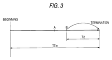
- For example, as for program information with record time TTm being extremely long, as shown in FIG. 3, if the playback position at which the pickup was positioned when the power of the record medium playback apparatus was turned off is slightly leaning to the termination position (indicated by B in FIG. 3) from the half of the record time of the whole program information (indicated by A in FIG. 3), playing back is started at the beginning position of program information next to that program information.
- In doing so, even when the remaining record time indicated by T2 in FIG. 3 is substantially long, the portion corresponding to T2 will be skipped. Therefore, it is not always preferable method to playback for a user.
- It is therefore an object of the invention to provide a record medium playback apparatus and a record medium playback method for effectively determining the playback start position of program information when the record medium playback apparatus is started.
- According to a first aspect of the invention, there is provided a record medium playback apparatus for playing back a record medium recording a plurality of pieces of program information and information including record time for each of the pieces of program information, the apparatus having: a playback section adapted to play back the program information; and a playback control section adapted to control a playback start position of the program information when the record medium playback apparatus is restarted after power thereof was turned off, wherein the playback control section determines the playback start position of the program information using a first sequence when the record time of the whole program information corresponding to the playback position at the power off is less than a predetermined time, and determines the playback start position of the program information using a second sequence when the record time of the whole program information corresponding to the playback position at the power off is equal to or longer than the predetermined time.
- According to a second aspect of the invention, there is provided a record medium playback method for playing back a record medium recording a plurality of pieces of program information and information including record time for each of the pieces of program information, the method including: when a record medium playback apparatus is restarted after power thereof was turned off, comparing the record time of the whole program information corresponding to the playback position at the power off with a predetermined time; determining a playback start position of program information using a first sequence when the record time is less than the predetermined time; determining a playback start position of program information using a second 'sequence when the record time is equal to or longer than the predetermined time; and starting playing back of the program information at the determined playback start position.
- In the Drawings;
- The above objects and advantages of the present invention will become more apparent by describing in detail preferred exemplary embodiments thereof with reference to the accompanying drawings, wherein:
- FIG. 1 is a diagram to show the configuration of an embodiment of a record medium playback apparatus according to the invention;
- FIG. 2 is a flowchart to show an embodiment of a record medium playback method according to the invention; and
- FIG. 3 is a schematic representation to show a problem involved in a record medium playback apparatus and a record medium playback method in a related art.
-
- Referring now to the accompanying drawings, there are shown preferred embodiments of a record medium playback apparatus and a record medium playback method according to the invention.
- In the embodiment, a record medium playback apparatus for playing back program information recorded on a optical disk will be discussed as an example.
- FIG. 1 is a diagram to show the configuration of an
optical disk player 10 of a record medium playback apparatus. Six pieces of program information (track numbers TNO. 1 to TNO. 6) are recorded in adata area 11a of anoptical disk 11 of a record medium with information such as track numbers and time codes (in hours/minutes/seconds format, for example). - Further, TOC (Table of Contents) information including the track numbers of the each pieces of program information, and time codes indicating the playback start and the playback end is recorded in a read-in
area 11b at the inner radius of theoptical disk 11 from thedata area 11a. - The
optical disk player 10 is provided with aturntable 14 on which theoptical disk 11 is placed for rotation and aspindle motor 13 for rotating theturntable 14. - On the other hand, a
pickup 15 for applying laser beam to the information record side of theoptical disk 11 and reading program information, afeed screw mechanism 18 for allowing thepickup 15 to reciprocate in the radial direction of theoptical disk 11, and acarriage motor 17 for rotating thefeed screw mechanism 18 are provided below theoptical disk 11 placed on theturntable 14. - The
feed screw mechanism 18 is rotated in the positive negative direction by a driving force supplied from thecarriage motor 17 for reciprocating thepickup 15 in the radial direction of theoptical disk 11. - The
optical disk player 10 is also provided with aservo control circuit 30 for controlling the rotation speed of the spindle motor '13 and the number of revolutions of thecarriage motor 17 and asignal demodulation circuit 20 for performing predetermined signal processing such as error correction processing and demodulation processing, for the program information read by thepickup 15. - The
optical disk player 10 is also provided with anaudio output circuit 19 consisting of a D/A converter for converting the program information subjected to the signal processing by thesignal demodulation circuit 20 into analog data, an amplifier for amplifying the program information converted into the analog data, a loudspeaker for outputting the amplified program information, and the like. ACPU 21 controls theservo control circuit 30 and thesignal demodulation circuit 20. - A
display section 23 displays data such as an elapsed time of playback of program information, and the track number. Anoperation section 22 is operated by the user to select the track number to play or to input an operation command to start and stop the playback. - In the described
optical disk player 10, when theoptical disk 11 is inserted through a disk slot (not shown) into the main unit of theoptical disk player 10, theoptical disk 11 is placed on theturntable 14. - Following a command from the
CPU 21, theservo control circuit 30 controls rotating thespindle motor 13 so as to rotate theoptical disk 11 at a constant linear speed. - Further, the
servo control circuit 30 controls thecarriage motor 17 for driving thefeed screw mechanism 18 so as to place laser beam of thepickup 15 at a predetermined position in the read-in area of theoptical disk 11. The TOC information read by thepickup 15 is subjected to signal processing by thesignal demodulation circuit 20 and is stored in memory contained in theCPU 21. - The
servo control circuit 30 also controls thecarriage motor 17 for driving thefeed screw mechanism 18 so as to place laser beam of thepickup 15 at the beginning position of the program information with track number TNO.1 in the data area. Thepickup 15 starts to read the program information with track number TNO.1 at the beginning thereof and the read program information is output through thesignal demodulation circuit 20 and theaudio output circuit 19. - When the user performs track number selection operation through the
operation section 22, theCPU 21 receives a signal of the selection operation and controls theservo control circuit 30 so as to place laser beam of thepickup 15 at the top position of the selected track number. Theservo control circuit 30 controls thecarriage motor 17 for placing laser beam of thepickup 15 at a predetermined position. - The
pickup 15 reads the program information with the selected track number and the read program information is output through thesignal demodulation circuit 20 and theaudio output circuit 19. - If the
optical disk player 10 functions as, for example, an in-car disk player installed in a vehicle, it is connected to an ACC line (accessory power line) of the vehicle and is started by a power supply voltage supplied via the ACC line from a battery of the vehicle. - In this case, the power of the
optical disk player 10 is turned 'off when an ACC switch placed in the ACC line is turned off. - If the
optical disk player 10 functions as, for example, a home disk player, it is connected to a power supply installed in a house, whereby a power supply voltage is supplied and theoptical disk player 10 is started. - If the
optical disk player 10 functions as, for example, a portable disk player, it is started by a power supply voltage supplied from a rechargeable battery or a dry battery in the disk player. In these cases (the case with a home disk player and a portable disk player), the power of theoptical disk player 10 is turned off when a power switch placed on theoptical disk player 10 is turned off. - The
CPU 21 stores as a program a sequence used to determine the playback start position of the program information recorded on theoptical disk 11 when theoptical disk player 10 is started again after power of theoptical disk player 10 was turned off. - That is, the
optical disk player 10 comprises a sequence used to determine the playback start position of the program information when theoptical disk player 10 is started again after the power switch was turned off while thepickup 15 is reading the programinformation recorded on the optical disk 11 (during the playback) or after playback is interrupted due to an unexpected accident such as a power failure or a battery exhaustion. - Next, the sequence will be discussed using a flowchart of FIG. 2. The
CPU 21 senses that the ACC switch of the vehicle or the power switch placed on theoptical disk player 10 is turned on, namely, theoptical disk player 10 is again started (step SS), and controls theservo control circuit 30 for rotating thespindle motor 13. - Further, the
CPU 21 causes thepickup 15 to read the time code (absolute address) of the playback position at which thepickup 15 was positioned when power of theoptical disk player 10 was turned on and the track number TNO.m of the program information corresponding to the playback position, and stores the time code (absolute address) and the track number TNO.m in the internal memory through the signal demodulation circuit 20 (steps S1 and S2). - The
CPU 21 computes record time TTm of the whole program information with the track number TNO.m, playback elapsed time LTm, and remaining record time RTm based on the absolute address and the TOC information previously recorded in the memory (step S3). - That is, the record time TTm of the whole program information is computed, for example, by subtracting the time code of playback start from the time code of playback end in the TOC information corresponding to the read track number TNO.m.
- The playback elapsed time LTm is computed, for example, by subtracting the time code of playback start in the TOC information corresponding to the read track number TNO. m from the read absolute address.
- The remaining record time RTm is computed, for example, by subtracting the found playback elapsed time LTm from the previously computed record time TTm of the whole program information.
- Next, the
CPU 21 determines whether or not the record time TTm of the whole program information with the track number TNO.m is shorter than a predetermined time (in the embodiment, for example, 60 seconds) (step S4). - If the
CPU 21 determines at step S4 that the record time TTm is shorter than the predetermined time, theCPU 21 switches the process to step S5; if theCPU 21 determines that the record time TTm is equal to or longer than the predetermined time, theCPU 21 switches the process to step S6. - In the embodiment, step S5 shown in the flowchart of FIG. 2 is called first sequence and steps S6 to S13 are called second sequence.
- If it is determined at step S4 that the record time TTm of the whole program information with the track number TNO.m is shorter than the predetermined time, the first sequence is executed for restarting playback at the beginning position of the program information with the track number TNO.m (step S5).
- The
CPU 21 controls thecarriage motor 17 for moving thepickup 15 so as to place laser beam of thepickup 15 at the beginning position of the program information with the track number TNO.m. - The
pickup 15 reads the program information at the beginning position thereof, whereby playing back the program information is started. - The predetermined time may be set as a fixed time in the
CPU 21 or may be set as a variable time that can be set as desired by the user through theoperation section 22. If the predetermined time is set as a variable time, for example, to play back aoptical disk 11 recording a plurality of pieces of program information each with a comparatively short record time, it is preferable to set the predetermined time to a longer time in a variable manner, thereby playing back the program information whose playback was interrupted can be reliably started at the beginning position of the program information. - If it is determined at step S4 that the record time TTm of the whole program information with the track number TNO.m is equal to or longer than the predetermined time, the second sequence is executed. The
CPU 21 finds a reference time used as the determination criterion as to whether or not playing back the program information with the track number TNO.m is to be started at the playback position at which thepickup 15 was positioned when power of theoptical disk player 10 was turned off (step S6). - At step S6, the
CPU 21 calculates two reference times of reference time Jrtm to be compared with the calculated playback elapsed time LTm of the program information with the track number TNO.m and reference time Jltm to be compared with the calculated remaining record time of the program information with the track number TNO.m. - The
CPU 21 multiplies the record time TTm of the whole program information with the track number TNO.m found at step S3 by a predetermined coefficient α (for example, α=0.1) to find the reference time Jrtm and the reference time Jltm. - At step S6, the record time TTm of the whole program information with the track number TNO.m is multiplied by the same coefficient α 'to find the same time for the reference time Jrtm and the reference time Jltm.
- The
CPU 21 compares either of the references times with a predetermined time. In the flowchart of FIG. 2, whether or not the reference time Jrtm is longer than a predetermined time (in the embodiment, 30 seconds) is determined (step S7). - The purpose of step S7 is as follows: When the record time of the whole program information is extremely long, if it is multiplied by a predetermined coefficient to find the reference time, it is estimated that the reference time itself becomes extremely long and therefore setting the reference time not fitted for determining the playback start position is eliminated. If the
CPU 21 determines at step S7 that the reference time is longer than the predetermined time, theCPU 21 sets the predetermined time as the reference time Jrtm and the reference time Jltm (step S8). - The
CPU 21 compares the found reference time Jrtm with the remaining record time RTm of the track number TNO.m and determines whether or not the remaining record time RTm is shorter than the reference time Jrtm (step S9). - If the
CPU 21 determines at step S9 that the remaining record time RTm is shorter than the reference time Jrtm, theCPU 21 increments the track number TNO.m and restarts playing back at the beginning position of the program information with track number TNO.m+1=track number TNO.x (step S10). - The
CPU 21 controls thecarriage motor 17 for moving thepickup 15 so as to place laser beam of thepickup 15 at the beginning position of the program information with the track number TNO.x. - The
pickup 15 reads the program information at the beginning position thereof, whereby playing back the program information is started. If theCPU 21 determines at step S9 that the remaining record time RTm of the track number TNO.m is equal to or longer than the reference time Jrtm, theCPU 21 compares the found reference time Jltm with the playback elapsed time LTm of the track number TNO.m and determines whether or not the playback elapsed time LTm is shorter than the reference time Jltm (step S12). - If the
CPU 21 determines at step S12 that the playback elapsed time LTm is shorter than the reference time Jltm, theCPU 21 restarts playing back at the beginning position of the program information with the track number TNO.m (step S11). - The
CPU 21 controls thecarriage motor 17 for moving thepickup 15 so as to place laser beam of thepickup 15 at the beginning position of the program information with the track number TNO.m. Thepickup 15 reads the program information at the beginning position thereof, whereby playing back the program information is started. If theCPU 21 determines at step S12 that the playback elapsed time LTm of the track number TNO.m is equal to or longer than the reference time Jltm, theCPU 21 starts playing back at the playback position at which thepickup 15 was positioned when the power of theoptical disk player 10 was turned off (step S13). - Then, the
CPU 21 starts playing back the program information With the track number TNO.m at the playback position. - Thus, in the
optical disk player 10 in the embodiment, when theoptical disk player 10 is started, the playback start position is determined based on the record time of the whole program information corresponding to the playback position at which thepickup 15 was positioned when the power of theoptical disk player 10 was turned off just before the starting. That is, if the program information has a comparatively short record time, the playback start position is determined the beginning position of the program information corresponding to the playback position according to the first sequence. - Thus, if it is known that the record time of the program information is short, even if playing back the same program information is repeated from the beginning, the repeated playback time is short and therefore an offensive feeling to the user is small.
- If the program information has a comparatively long record time, the playback start position is determined according to the second sequence. That is, if the playback elapsed time of the program information corresponding to the playback position at which the
pickup 15 was positioned when the power of theoptical disk player 10 was turned off is comparatively short, the beginning position of the program information is determined the playbackstart position. - From the fact that the playback elapsed time is comparatively short, it is considered that playing back the program information is interrupted shortly after it is started. Thus, playing back the program information is started again at the beginning position of the program information, whereby an offensive feeling to the user is eliminated.
- If the remaining record time of the program information corresponding to the playback position at which the
pickup 15 was positioned when the power of theoptical disk player 10 was turned off is comparatively short, the beginning position of program information next to that program information is determined the playback start position. From the fact that the remaining record time is comparatively short, it is considered that playing back the program information is interrupted when it is about to reach the termination and the user has listened to most of the program information. Thus, playing back is restarted at the beginning position of program information next to that program information, whereby an offensive feeling to the user is eliminated. - If the playback position at which the
pickup 15 was positioned when the power of theoptical disk player 10 was turned off is slightly leaning to the termination position from the half of the record time of the whole program information, the playback position is determined the playback start position. In doing so, restarting of playing back at the beginning position of the next program although the remaining record time is long is avoided, and an offensive feeling to the user is eliminated. - As described above in detail, in the embodiment of the invention, if the ACC switch or the power switch placed on the
optical disk player 10 is turned off while program information is being played back or if playback is interrupted because of an unexpected accident such as a power failure or a battery exhaustion, the playback start position when theoptical disk player 10 is started is determined using the first sequence and the second sequence. Thus, in addition to eliminating "playback with the beginning part skipped" and "playback with the last part remaining," if the remaining record time is long, the program information is played back without ignoring the remaining part of the program information, so that it is made possible to more eliminate an offensive feeling to the user. - In the embodiment, the record medium playback apparatus for playing back program information recorded on a optical disk has been described as an example, but the invention is not limited to it. For example, the invention can also be applied to a record medium playback apparatus for playing back a magneto-optical disk such as an MO disk or an MD (Mini Disk). The invention can also be applied to a record medium playback apparatus for playing back a read-only type disk such as a CD (Compact Disk) or a DVD (Digital Versatile Disk), and also be applied to a record medium playback apparatus for playing back a rewritable type disk such as CD-R, CD-RW, DVD-R, DVD-RW.
- In the description of the embodiment, the two reference times of the reference time to be compared with the playback elapsed time and the reference time to be compared with the remaining record time are computed and are compared with the playback elapsed time and the remaining record time. However, only either of the reference times may be computed and compared with the corresponding record time.
- The sequence of comparing the reference time with the remaining record time and then comparing the reference time with the playback elapsed time has been described, but the comparing order may be reversed. Further, in the description given above, the two reference times of the reference time to be compared with the playback elapsed time and the reference time to be compared with the remaining record time are set to the same time, but may be set to different times.
- In the description given above, if the record time of the whole program information is shorter than the predetermined time, the beginning position of the program information is determined the playback start position according to the first sequence. However, the sequence may be a sequence of setting the playback start position to any other position than the beginning position of the program information, for example, the beginning position of program information next to that program information or the playback position at which the pickup was positioned when the power of the record medium playback apparatus was turned off. If the program information has a comparatively short record time, it is also possible that the user may want to skip again playing back the program information, in which case the playback start position can be set appropriately as desired.
- Although the present invention has been shown and described with reference to specific preferred embodiments, various changes and modifications will be apparent to those skilled in the art from the teachings herein. Such changes and modifications as are obvious are deemed to come within the spirit, scope and contemplation of the invention as defined in the appended claims.
Claims (5)
- A record medium playback apparatus for playing back a record medium recording a plurality of pieces of program information and information including record time for each of the pieces of program information, the apparatus comprising:wherein the playback control section determines the playback start position of the program information using a first sequence when the record time of the whole program information corresponding to the playback position at the power off is less than a predetermined time, and determines the playback start position of the program information using a second sequence when the record time of the whole program information corresponding to the playback position at the power off is equal to or longer than the predetermined time.a playback section adapted to play back the program information; anda playback control section adapted to control a playback start position of the program information when the record medium playback apparatus is restarted after power thereof was turned off,
- The record medium playback apparatus as claimed in claim 1,
wherein the second sequence comprises setting reference time used as a determination criterion as to whether or not playing back the program information is to be started at the playback position at the power off, and comparing the reference time with playback elapsed time until the power off of the program information corresponding to the playback position at the power off, thereby determining the playback start position. - The record medium playback apparatus as claimed in claim 1,
wherein the second sequence comprises setting reference time used as a determination criterion as to whether or not playing back the program information is to be started at the playback position at the power off, and comparing the reference time with a remaining record time computed from playback elapsed time until the power off time of the program information corresponding to the playback position at the power off and the record time, thereby determining the playback start position. - The record medium playback apparatus as claimed in claim 1,
wherein the first sequence comprises determining that the playback start position is any of the playback position at the power off, the beginning position of the program information corresponding to the playback position at the power off, or the beginning position of program information next to the program information corresponding to the playback position at the power off. - A record medium playback method for playing back a record medium recording a plurality of pieces of program information and information including record time for each of the pieces of program information, the method comprising:when a record medium playback apparatus is restarted after power thereof was turned off, comparing the record time of the whole program information corresponding to the playback position at the power off with a predetermined time;determining a playback start position of program information using a first sequence when the record time is less than the predetermined time;determining a playback start position of program information using a second sequence when the record time is equal to or longer than the predetermined time; andstarting playing back of the program information at the determined playback start position.
Applications Claiming Priority (2)
| Application Number | Priority Date | Filing Date | Title |
|---|---|---|---|
| JP2002150404 | 2002-05-24 | ||
| JP2002150404A JP2003346464A (en) | 2002-05-24 | 2002-05-24 | Recording medium reproducing apparatus and reproducing method for the same |
Publications (2)
| Publication Number | Publication Date |
|---|---|
| EP1365411A2 true EP1365411A2 (en) | 2003-11-26 |
| EP1365411A3 EP1365411A3 (en) | 2004-11-24 |
Family
ID=29397959
Family Applications (1)
| Application Number | Title | Priority Date | Filing Date |
|---|---|---|---|
| EP03253119A Withdrawn EP1365411A3 (en) | 2002-05-24 | 2003-05-19 | Record medium playback apparatus and record medium playback method |
Country Status (3)
| Country | Link |
|---|---|
| US (1) | US7016268B2 (en) |
| EP (1) | EP1365411A3 (en) |
| JP (1) | JP2003346464A (en) |
Cited By (2)
| Publication number | Priority date | Publication date | Assignee | Title |
|---|---|---|---|---|
| EP1983459A3 (en) * | 2007-04-16 | 2016-03-02 | Samsung Electronics Co., Ltd. | Digital rights management method and digital rights management-enabled portable device |
| EP3076393A1 (en) * | 2015-03-30 | 2016-10-05 | Canon Kabushiki Kaisha | Reproduction control apparatus and control method for the same |
Families Citing this family (5)
| Publication number | Priority date | Publication date | Assignee | Title |
|---|---|---|---|---|
| EP1571671A4 (en) * | 2002-12-13 | 2008-04-02 | Matsushita Electric Ind Co Ltd | Optical disc device |
| EP1714284A4 (en) * | 2004-01-15 | 2008-09-17 | Milsys Ltd | Removable medium with bookmark |
| JP3894226B1 (en) * | 2006-02-16 | 2007-03-14 | オンキヨー株式会社 | REPRODUCTION CONTROL DEVICE, REPRODUCTION CONTROL PROGRAM, AND CONTENT REPRODUCTION DEVICE |
| TW200826078A (en) * | 2006-12-15 | 2008-06-16 | Innolux Display Corp | Digital video disc player |
| CN103680560A (en) * | 2012-08-31 | 2014-03-26 | 鸿富锦精密工业(深圳)有限公司 | Electronic device and file play control method |
Citations (1)
| Publication number | Priority date | Publication date | Assignee | Title |
|---|---|---|---|---|
| EP0903743A2 (en) * | 1997-09-17 | 1999-03-24 | Matsushita Electric Industrial Co., Ltd | Video data editing apparatus and computer-readable recording medium storing an editing program |
Family Cites Families (16)
| Publication number | Priority date | Publication date | Assignee | Title |
|---|---|---|---|---|
| BE902324A (en) * | 1985-04-30 | 1985-08-16 | Staar Sa | APPARATUS FOR THE SELECTIVE AND / OR SUCCESSIVE REPRODUCTION AND / OR RECORDING OF INFORMATION MEDIA. |
| JPS62214576A (en) * | 1986-03-14 | 1987-09-21 | Pioneer Electronic Corp | Pickup position control method |
| JPS62287464A (en) * | 1986-06-06 | 1987-12-14 | Pioneer Electronic Corp | Disk reproducing device |
| JP2609542B2 (en) * | 1988-10-04 | 1997-05-14 | パイオニア株式会社 | Disc player |
| JPH0437495A (en) | 1990-05-31 | 1992-02-07 | Fanuc Ltd | Laser beam input device for laser robot |
| JPH04254959A (en) * | 1991-02-05 | 1992-09-10 | Sony Corp | Disk player |
| JPH0536192A (en) * | 1991-07-30 | 1993-02-12 | Matsushita Electric Ind Co Ltd | Music reproducing device |
| KR100283967B1 (en) * | 1992-04-08 | 2001-03-02 | 이데이 노부유끼 | CD-ROM disc player |
| JP3396894B2 (en) * | 1992-05-14 | 2003-04-14 | ソニー株式会社 | Sound reproduction device |
| JPH08241565A (en) * | 1995-03-03 | 1996-09-17 | Toshiba Corp | Portable computer |
| JPH10508138A (en) * | 1995-08-22 | 1998-08-04 | フィリップス エレクトロニクス ネムローゼ フェンノートシャップ | Player for reading audio and / or video signals from a medium |
| KR100283948B1 (en) * | 1997-09-12 | 2001-05-02 | 윤종용 | Apparatus for controlling disk player and method therefor |
| SG82587A1 (en) * | 1997-10-21 | 2001-08-21 | Sony Corp | Recording apparatus, recording method, playback apparatus, playback method, recording/playback apparatus, recording/playback method, presentation medium and recording medium |
| JP3873523B2 (en) * | 1999-05-21 | 2007-01-24 | ソニー株式会社 | Playback device |
| JP2001035063A (en) * | 1999-07-15 | 2001-02-09 | Kenwood Corp | Reproducing device provided with resume function |
| US6396777B1 (en) * | 2000-05-30 | 2002-05-28 | Delphi Technologies, Inc. | Compact disk player instant-on feature |
-
2002
- 2002-05-24 JP JP2002150404A patent/JP2003346464A/en active Pending
-
2003
- 2003-05-19 EP EP03253119A patent/EP1365411A3/en not_active Withdrawn
- 2003-05-20 US US10/441,184 patent/US7016268B2/en not_active Expired - Fee Related
Patent Citations (1)
| Publication number | Priority date | Publication date | Assignee | Title |
|---|---|---|---|---|
| EP0903743A2 (en) * | 1997-09-17 | 1999-03-24 | Matsushita Electric Industrial Co., Ltd | Video data editing apparatus and computer-readable recording medium storing an editing program |
Cited By (6)
| Publication number | Priority date | Publication date | Assignee | Title |
|---|---|---|---|---|
| EP1983459A3 (en) * | 2007-04-16 | 2016-03-02 | Samsung Electronics Co., Ltd. | Digital rights management method and digital rights management-enabled portable device |
| EP3076393A1 (en) * | 2015-03-30 | 2016-10-05 | Canon Kabushiki Kaisha | Reproduction control apparatus and control method for the same |
| KR20160117197A (en) * | 2015-03-30 | 2016-10-10 | 캐논 가부시끼가이샤 | Reproduction control apparatus and control method for the same |
| RU2631262C1 (en) * | 2015-03-30 | 2017-09-20 | Кэнон Кабусики Кайся | Playback control unit and playback control method |
| US9959904B2 (en) | 2015-03-30 | 2018-05-01 | Canon Kabushiki Kaisha | Reproduction control apparatus and control method for the same |
| KR101984490B1 (en) | 2015-03-30 | 2019-09-03 | 캐논 가부시끼가이샤 | Reproduction control apparatus and control method for the same |
Also Published As
| Publication number | Publication date |
|---|---|
| US20030218942A1 (en) | 2003-11-27 |
| US7016268B2 (en) | 2006-03-21 |
| EP1365411A3 (en) | 2004-11-24 |
| JP2003346464A (en) | 2003-12-05 |
Similar Documents
| Publication | Publication Date | Title |
|---|---|---|
| US7016268B2 (en) | Optical reproducing system having resume function based on recording time of each program on the medium | |
| JP2002230893A (en) | Information recording and reproducing device, information recording and reproducing method, and program recording medium recorded with recording and reproducing procedure program | |
| US4882719A (en) | Disk playing method for disk player | |
| JPH11203790A (en) | Recording medium information reader | |
| US4926404A (en) | Disk playing method for disk player | |
| US6600699B2 (en) | Apparatus for searching of recorded information | |
| JPH06338180A (en) | Digital audio disk player | |
| JP2599235B2 (en) | In-vehicle recording medium playback device | |
| JP2948431B2 (en) | Recording and playback device | |
| JP2955499B2 (en) | Method and apparatus for storing TOC information on recording medium | |
| JP3361612B2 (en) | Disk unit | |
| JP2704995B2 (en) | Optical disk recording device | |
| JP2566325Y2 (en) | Optical disk recording and playback device | |
| JP2003187562A (en) | Disk changer device and reproducing method | |
| JPH0632161B2 (en) | Disc player | |
| JPH07296485A (en) | Disk device | |
| JPH06295570A (en) | Optical disk recording device | |
| JPH10143984A (en) | Disk discrimination method and disk reproducing device | |
| JPH0636460A (en) | Disk reproducing device | |
| JPH05101613A (en) | Optical information reproducing device | |
| JPH05182420A (en) | Optical disk recorder | |
| JPH11232847A (en) | Reproduction order storing method and its device | |
| JPH11288576A (en) | Disk device and its recording method | |
| JPH0863944A (en) | Disk recording and reproducing device and disk | |
| KR960035539A (en) | How to play an optical disc randomly |
Legal Events
| Date | Code | Title | Description |
|---|---|---|---|
| PUAI | Public reference made under article 153(3) epc to a published international application that has entered the european phase |
Free format text: ORIGINAL CODE: 0009012 |
|
| AK | Designated contracting states |
Kind code of ref document: A2 Designated state(s): AT BE BG CH CY CZ DE DK EE ES FI FR GB GR HU IE IT LI LU MC NL PT RO SE SI SK TR |
|
| AX | Request for extension of the european patent |
Extension state: AL LT LV MK |
|
| PUAL | Search report despatched |
Free format text: ORIGINAL CODE: 0009013 |
|
| AK | Designated contracting states |
Kind code of ref document: A3 Designated state(s): AT BE BG CH CY CZ DE DK EE ES FI FR GB GR HU IE IT LI LU MC NL PT RO SE SI SK TR |
|
| AX | Request for extension of the european patent |
Extension state: AL LT LV MK |
|
| RIC1 | Information provided on ipc code assigned before grant |
Ipc: 7G 11B 21/08 B Ipc: 7G 11B 19/12 B Ipc: 7G 11B 19/02 B Ipc: 7G 11B 27/10 A |
|
| 17P | Request for examination filed |
Effective date: 20050511 |
|
| AKX | Designation fees paid |
Designated state(s): DE FR GB |
|
| STAA | Information on the status of an ep patent application or granted ep patent |
Free format text: STATUS: THE APPLICATION IS DEEMED TO BE WITHDRAWN |
|
| 18D | Application deemed to be withdrawn |
Effective date: 20091201 |