EP1360935A1 - Strip containing a series of fluid sampling and testing devices and method of making, packaging and using it - Google Patents
Strip containing a series of fluid sampling and testing devices and method of making, packaging and using it Download PDFInfo
- Publication number
- EP1360935A1 EP1360935A1 EP03252884A EP03252884A EP1360935A1 EP 1360935 A1 EP1360935 A1 EP 1360935A1 EP 03252884 A EP03252884 A EP 03252884A EP 03252884 A EP03252884 A EP 03252884A EP 1360935 A1 EP1360935 A1 EP 1360935A1
- Authority
- EP
- European Patent Office
- Prior art keywords
- testers
- strip
- tester
- fluid
- cassette
- Prior art date
- Legal status (The legal status is an assumption and is not a legal conclusion. Google has not performed a legal analysis and makes no representation as to the accuracy of the status listed.)
- Granted
Links
Images


Classifications
-
- G—PHYSICS
- G01—MEASURING; TESTING
- G01N—INVESTIGATING OR ANALYSING MATERIALS BY DETERMINING THEIR CHEMICAL OR PHYSICAL PROPERTIES
- G01N33/00—Investigating or analysing materials by specific methods not covered by groups G01N1/00 - G01N31/00
- G01N33/48—Biological material, e.g. blood, urine; Haemocytometers
- G01N33/483—Physical analysis of biological material
- G01N33/487—Physical analysis of biological material of liquid biological material
- G01N33/4875—Details of handling test elements, e.g. dispensing or storage, not specific to a particular test method
- G01N33/48764—Test tape taken off a spool
-
- A—HUMAN NECESSITIES
- A61—MEDICAL OR VETERINARY SCIENCE; HYGIENE
- A61B—DIAGNOSIS; SURGERY; IDENTIFICATION
- A61B5/00—Measuring for diagnostic purposes; Identification of persons
- A61B5/15—Devices for taking samples of blood
- A61B5/150007—Details
- A61B5/150015—Source of blood
- A61B5/150022—Source of blood for capillary blood or interstitial fluid
-
- A—HUMAN NECESSITIES
- A61—MEDICAL OR VETERINARY SCIENCE; HYGIENE
- A61B—DIAGNOSIS; SURGERY; IDENTIFICATION
- A61B5/00—Measuring for diagnostic purposes; Identification of persons
- A61B5/15—Devices for taking samples of blood
- A61B5/150007—Details
- A61B5/150053—Details for enhanced collection of blood or interstitial fluid at the sample site, e.g. by applying compression, heat, vibration, ultrasound, suction or vacuum to tissue; for reduction of pain or discomfort; Skin piercing elements, e.g. blades, needles, lancets or canulas, with adjustable piercing speed
- A61B5/150061—Means for enhancing collection
- A61B5/150068—Means for enhancing collection by tissue compression, e.g. with specially designed surface of device contacting the skin area to be pierced
-
- A—HUMAN NECESSITIES
- A61—MEDICAL OR VETERINARY SCIENCE; HYGIENE
- A61B—DIAGNOSIS; SURGERY; IDENTIFICATION
- A61B5/00—Measuring for diagnostic purposes; Identification of persons
- A61B5/15—Devices for taking samples of blood
- A61B5/150007—Details
- A61B5/150206—Construction or design features not otherwise provided for; manufacturing or production; packages; sterilisation of piercing element, piercing device or sampling device
- A61B5/150213—Venting means
-
- A—HUMAN NECESSITIES
- A61—MEDICAL OR VETERINARY SCIENCE; HYGIENE
- A61B—DIAGNOSIS; SURGERY; IDENTIFICATION
- A61B5/00—Measuring for diagnostic purposes; Identification of persons
- A61B5/15—Devices for taking samples of blood
- A61B5/150007—Details
- A61B5/150206—Construction or design features not otherwise provided for; manufacturing or production; packages; sterilisation of piercing element, piercing device or sampling device
- A61B5/150259—Improved gripping, e.g. with high friction pattern or projections on the housing surface or an ergonometric shape
-
- A—HUMAN NECESSITIES
- A61—MEDICAL OR VETERINARY SCIENCE; HYGIENE
- A61B—DIAGNOSIS; SURGERY; IDENTIFICATION
- A61B5/00—Measuring for diagnostic purposes; Identification of persons
- A61B5/15—Devices for taking samples of blood
- A61B5/150007—Details
- A61B5/150206—Construction or design features not otherwise provided for; manufacturing or production; packages; sterilisation of piercing element, piercing device or sampling device
- A61B5/150274—Manufacture or production processes or steps for blood sampling devices
- A61B5/150282—Manufacture or production processes or steps for blood sampling devices for piercing elements, e.g. blade, lancet, canula, needle
-
- A—HUMAN NECESSITIES
- A61—MEDICAL OR VETERINARY SCIENCE; HYGIENE
- A61B—DIAGNOSIS; SURGERY; IDENTIFICATION
- A61B5/00—Measuring for diagnostic purposes; Identification of persons
- A61B5/15—Devices for taking samples of blood
- A61B5/150007—Details
- A61B5/150358—Strips for collecting blood, e.g. absorbent
-
- A—HUMAN NECESSITIES
- A61—MEDICAL OR VETERINARY SCIENCE; HYGIENE
- A61B—DIAGNOSIS; SURGERY; IDENTIFICATION
- A61B5/00—Measuring for diagnostic purposes; Identification of persons
- A61B5/15—Devices for taking samples of blood
- A61B5/150007—Details
- A61B5/150374—Details of piercing elements or protective means for preventing accidental injuries by such piercing elements
- A61B5/150381—Design of piercing elements
- A61B5/150412—Pointed piercing elements, e.g. needles, lancets for piercing the skin
- A61B5/150419—Pointed piercing elements, e.g. needles, lancets for piercing the skin comprising means for capillary action
-
- A—HUMAN NECESSITIES
- A61—MEDICAL OR VETERINARY SCIENCE; HYGIENE
- A61B—DIAGNOSIS; SURGERY; IDENTIFICATION
- A61B5/00—Measuring for diagnostic purposes; Identification of persons
- A61B5/15—Devices for taking samples of blood
- A61B5/150007—Details
- A61B5/150374—Details of piercing elements or protective means for preventing accidental injuries by such piercing elements
- A61B5/150381—Design of piercing elements
- A61B5/150412—Pointed piercing elements, e.g. needles, lancets for piercing the skin
- A61B5/150435—Specific design of proximal end
-
- A—HUMAN NECESSITIES
- A61—MEDICAL OR VETERINARY SCIENCE; HYGIENE
- A61B—DIAGNOSIS; SURGERY; IDENTIFICATION
- A61B5/00—Measuring for diagnostic purposes; Identification of persons
- A61B5/15—Devices for taking samples of blood
- A61B5/150007—Details
- A61B5/150374—Details of piercing elements or protective means for preventing accidental injuries by such piercing elements
- A61B5/150381—Design of piercing elements
- A61B5/150503—Single-ended needles
-
- A—HUMAN NECESSITIES
- A61—MEDICAL OR VETERINARY SCIENCE; HYGIENE
- A61B—DIAGNOSIS; SURGERY; IDENTIFICATION
- A61B5/00—Measuring for diagnostic purposes; Identification of persons
- A61B5/15—Devices for taking samples of blood
- A61B5/151—Devices specially adapted for taking samples of capillary blood, e.g. by lancets, needles or blades
- A61B5/15101—Details
- A61B5/15103—Piercing procedure
- A61B5/15107—Piercing being assisted by a triggering mechanism
- A61B5/15111—Semi-automatically triggered, e.g. at the end of the cocking procedure, for instance by biasing the main drive spring or when reaching sufficient contact pressure, the piercing device is automatically triggered without any deliberate action by the user
-
- A—HUMAN NECESSITIES
- A61—MEDICAL OR VETERINARY SCIENCE; HYGIENE
- A61B—DIAGNOSIS; SURGERY; IDENTIFICATION
- A61B5/00—Measuring for diagnostic purposes; Identification of persons
- A61B5/15—Devices for taking samples of blood
- A61B5/151—Devices specially adapted for taking samples of capillary blood, e.g. by lancets, needles or blades
- A61B5/15101—Details
- A61B5/15115—Driving means for propelling the piercing element to pierce the skin, e.g. comprising mechanisms based on shape memory alloys, magnetism, solenoids, piezoelectric effect, biased elements, resilient elements, vacuum or compressed fluids
- A61B5/15117—Driving means for propelling the piercing element to pierce the skin, e.g. comprising mechanisms based on shape memory alloys, magnetism, solenoids, piezoelectric effect, biased elements, resilient elements, vacuum or compressed fluids comprising biased elements, resilient elements or a spring, e.g. a helical spring, leaf spring, or elastic strap
-
- A—HUMAN NECESSITIES
- A61—MEDICAL OR VETERINARY SCIENCE; HYGIENE
- A61B—DIAGNOSIS; SURGERY; IDENTIFICATION
- A61B5/00—Measuring for diagnostic purposes; Identification of persons
- A61B5/15—Devices for taking samples of blood
- A61B5/151—Devices specially adapted for taking samples of capillary blood, e.g. by lancets, needles or blades
- A61B5/15146—Devices loaded with multiple lancets simultaneously, e.g. for serial firing without reloading, for example by use of stocking means.
- A61B5/15148—Constructional features of stocking means, e.g. strip, roll, disc, cartridge, belt or tube
- A61B5/15149—Arrangement of piercing elements relative to each other
- A61B5/15151—Each piercing element being stocked in a separate isolated compartment
-
- A—HUMAN NECESSITIES
- A61—MEDICAL OR VETERINARY SCIENCE; HYGIENE
- A61B—DIAGNOSIS; SURGERY; IDENTIFICATION
- A61B5/00—Measuring for diagnostic purposes; Identification of persons
- A61B5/15—Devices for taking samples of blood
- A61B5/151—Devices specially adapted for taking samples of capillary blood, e.g. by lancets, needles or blades
- A61B5/15146—Devices loaded with multiple lancets simultaneously, e.g. for serial firing without reloading, for example by use of stocking means.
- A61B5/15148—Constructional features of stocking means, e.g. strip, roll, disc, cartridge, belt or tube
- A61B5/15149—Arrangement of piercing elements relative to each other
- A61B5/15153—Multiple piercing elements stocked in a single compartment
-
- A—HUMAN NECESSITIES
- A61—MEDICAL OR VETERINARY SCIENCE; HYGIENE
- A61B—DIAGNOSIS; SURGERY; IDENTIFICATION
- A61B5/00—Measuring for diagnostic purposes; Identification of persons
- A61B5/15—Devices for taking samples of blood
- A61B5/151—Devices specially adapted for taking samples of capillary blood, e.g. by lancets, needles or blades
- A61B5/15146—Devices loaded with multiple lancets simultaneously, e.g. for serial firing without reloading, for example by use of stocking means.
- A61B5/15148—Constructional features of stocking means, e.g. strip, roll, disc, cartridge, belt or tube
- A61B5/15157—Geometry of stocking means or arrangement of piercing elements therein
- A61B5/15165—Piercing elements stocked in or on a strip
- A61B5/15169—Characterized by a rolled strip
-
- A—HUMAN NECESSITIES
- A61—MEDICAL OR VETERINARY SCIENCE; HYGIENE
- A61B—DIAGNOSIS; SURGERY; IDENTIFICATION
- A61B5/00—Measuring for diagnostic purposes; Identification of persons
- A61B5/15—Devices for taking samples of blood
- A61B5/151—Devices specially adapted for taking samples of capillary blood, e.g. by lancets, needles or blades
- A61B5/15146—Devices loaded with multiple lancets simultaneously, e.g. for serial firing without reloading, for example by use of stocking means.
- A61B5/15148—Constructional features of stocking means, e.g. strip, roll, disc, cartridge, belt or tube
- A61B5/15157—Geometry of stocking means or arrangement of piercing elements therein
- A61B5/15165—Piercing elements stocked in or on a strip
- A61B5/15173—Characterized by propelling the piercing element parallel to the direction of movement of the strip
-
- A—HUMAN NECESSITIES
- A61—MEDICAL OR VETERINARY SCIENCE; HYGIENE
- A61B—DIAGNOSIS; SURGERY; IDENTIFICATION
- A61B5/00—Measuring for diagnostic purposes; Identification of persons
- A61B5/15—Devices for taking samples of blood
- A61B5/151—Devices specially adapted for taking samples of capillary blood, e.g. by lancets, needles or blades
- A61B5/15146—Devices loaded with multiple lancets simultaneously, e.g. for serial firing without reloading, for example by use of stocking means.
- A61B5/15182—Means for keeping track or checking of the total number of piercing elements already used or the number of piercing elements still remaining in the stocking, e.g. by check window, counter, display
-
- A—HUMAN NECESSITIES
- A61—MEDICAL OR VETERINARY SCIENCE; HYGIENE
- A61B—DIAGNOSIS; SURGERY; IDENTIFICATION
- A61B5/00—Measuring for diagnostic purposes; Identification of persons
- A61B5/15—Devices for taking samples of blood
- A61B5/157—Devices characterised by integrated means for measuring characteristics of blood
-
- G—PHYSICS
- G01—MEASURING; TESTING
- G01N—INVESTIGATING OR ANALYSING MATERIALS BY DETERMINING THEIR CHEMICAL OR PHYSICAL PROPERTIES
- G01N35/00—Automatic analysis not limited to methods or materials provided for in any single one of groups G01N1/00 - G01N33/00; Handling materials therefor
- G01N35/00009—Automatic analysis not limited to methods or materials provided for in any single one of groups G01N1/00 - G01N33/00; Handling materials therefor provided with a sample supporting tape, e.g. with absorbent zones
-
- Y—GENERAL TAGGING OF NEW TECHNOLOGICAL DEVELOPMENTS; GENERAL TAGGING OF CROSS-SECTIONAL TECHNOLOGIES SPANNING OVER SEVERAL SECTIONS OF THE IPC; TECHNICAL SUBJECTS COVERED BY FORMER USPC CROSS-REFERENCE ART COLLECTIONS [XRACs] AND DIGESTS
- Y10—TECHNICAL SUBJECTS COVERED BY FORMER USPC
- Y10T—TECHNICAL SUBJECTS COVERED BY FORMER US CLASSIFICATION
- Y10T436/00—Chemistry: analytical and immunological testing
- Y10T436/11—Automated chemical analysis
- Y10T436/110833—Utilizing a moving indicator strip or tape
Definitions
- This invention relates to the sampling and testing of physiological fluid. More particularly, the invention relates to continuous strips of physiological fluid sampling and testing devices, the manufacturing thereof and the use thereof within a meter configured for individually dispensing such sampling and testing devices.
- Analyte concentration determination in physiological samples is of ever increasing importance to today's society. Such assays find use in a variety of application settings, including clinical laboratory testing, home testing, etc., where the results of such testing play a prominent role in the diagnosis and management of a variety of disease conditions. Analytes of interest include glucose for diabetes management, cholesterol for monitoring cardiovascular conditions, drugs for monitoring levels of therapeutic agents, and identifying illegal levels of drugs, and the like. In response to this growing importance of analyte concentration determination, a variety of analyte concentration determination protocols and devices for both clinical and home testing have been developed.
- test elements such as test strips, lancing members, meters and the like
- visual acuity and manual dexterity of the user which in the case of people with diabetes is subject to deterioration over the course of the disease state.
- testing procedures can become significantly difficult and requires additional assistance from ancillary devices or personnel.
- a typical procedure for making a glucose measurement with the use of a - test strip involves the following actions or steps (but not necessarily in the order given): (1) removing supplies from a carrying case, (2) removing a lancing device loading cap or door, (3) removing and disposing of a used lancet from the lancing device, (4) inserting the lancet in the lancing device, (5) twisting off a protective cap from the lancet, (6) replacing the lancing device cap, (7) cocking the lancing device, (8) opening a test strip vial/ container, (9) removing a strip from the container and inserting or interfacing it with a meter, (10) holding a lancing device to the skin, (11) firing the lancing device, (12) removing the lancing device from the skin, (13) extracting a sample, (14) applying sample to the test strip and obtaining results of the measurement; (15) disposing of the test strip, (16) cleaning the test site, and (17) returning supplies to the carrying case.
- certain glucose measurement systems and protocols may involve fewer
- test strip dispensers are configured to both store and advance successive test strips upon actuation. Examples of such devices are presented in U.S. Patent Nos. 5,510,266; 5,660,791; 5,575,403; 5,736,103; 5,757,666; 5,797,693; 5,856,195 and PCT Publication WO 99/44508. Some of these test strip dispensers devices also include meter functionality for testing physiologic fluid.
- U.S. Patent No. 6,228,100 discloses a structure configured for sequential firing of a number of lancets, one at a time, in order to eliminate the requirement that a user remove and replace each lancet individually before and after use.
- this device does not include any sensor components or functions.
- other systems such as those described in U.S. Patent Nos. 6,352,514; 6,332,871; 6,183,489; 6,099,484; 6,056,701 and 5,820,570, integrate the test strip and lancing functions within a single device, the test strip and lancet are separate components which must be loaded into the meter or dispenser individually.
- U.S. Patent No. 5,971,941 attempts to combine the functionality of each of the preceding classes of test strip devices.
- it includes a magazine of test strips, test strip advancement and dispensing features, a meter with a display and an automated lancing mechanism all housed within a single box. While presenting some measure of improvement in user convenience, the test strip and lancing features are independent from each other causing the user to take two steps in lancing and transferring sample to a test strip.
- WO 02/49507 discloses a meter including a microneedle which extracts fluid from a subject and is selectively switched between multiple sensor elements. While offering a slight improvement over prior devices, such configurations typically require complex componentry which can be difficult to operate and are costly to produce. Further, the more componentry and moving parts within a device, the more questionable the reliability of the device.
- test strip fabrication where both sensor and lancing functions and structures are provided on a single test strip.
- Certain web-based methods have been used to make such fully integrated test strips which are singulated after fabrication prior to being collectively packaged in a cartridge, magazine, cassette or the like. While such test strips packaging reduces, to some degree, the necessary handling by a user, this modality still requires additional manufacturing and packaging steps.
- test strip dispensing there is continued interest in the development of new devices and methods for use in test strip dispensing. Of particular interest would be the development of such devices and methods which are easy and inexpensive to manufacture, have minimal components, are portable and easy to use, particularly for visually and dextrally impaired individuals, and involve no direct contact and minimal handling by the user, thereby minimizing the risk of injury to the user and damage and/or contamination to the test strip devices contained therein.
- the invention is of assistance in reducing barriers to patient self-monitoring and therefore result in improved outcomes in the management of disease, such as diabetes.
- the present invention provides continuous strips of testers in an individually-sealed packaging which maintains the testers in a sterile condition until used.
- the subject testers include a test strip sensor integrated with a microneedle for accessing and collecting a sample of physiological fluid and for measuring a chemical characteristic, such as target analyte concentration, of the sampled fluid.
- the present invention further provides cassettes of the subject strips for removable engagement with a meter for individually dispensing the testers and for facilitating the analysis of the sampled fluid.
- systems which include the subject strips and cassettes and such a meter. Methods of using the strips and cassettes are also provided, along with kits for practicing the subject methods.
- An aspect of the present invention is to provide devices and methods for facilitating a user in the self-testing of analyte concentrations, such blood glucose levels. More particularly, such devices facilitate the easy, convenient and safe dispensing of testers for the measuring of analyte concentrations and the subsequent storage of such testers after they have been used.
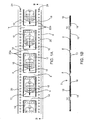
- Fig. 1A is a planar view of one embodiment of according to the present invention of a strip of singulated testers.
- Fig. 1B is a side view of the strip of Fig. 1A taken along the line B-B.
- Fig. 2A is a planar view of another embodiment according to the present invention of a strip of interconnected testers.
- Fig. 2B is a side view of the strip of Fig. 2A taken along the line B-B.
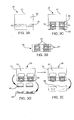
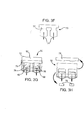
- FigS. 3A-3K illustrate various steps of a continuous web-based method of the present invention for fabricating the strip of testers of Figs. 1A and 1B.
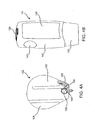
- Fig. 4A is an isometric view of a cassette of the present invention for storing a strip of testers of the present invention.
- Fig. 4B is an isometric view of the front side of a meter of the present invention for use with the cassette of Fig. 4A.
- Fig. 4C is an isometric view of the cassette of Fig. 4A in the process of engagement with the meter of Fig. 4B.
- Fig. 4D is an isometric view of the cassette of Fig. 4A fully engaged within the meter of Fig. 4B.
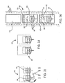
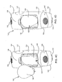
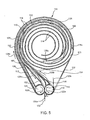
- Fig. 5 is a cross-sectional planar view of the cassette of Fig. 4A.
- Fig. 6 illustrates a strip of testers operatively engaged with a portion of the internal componentry of a cassette of the present invention.
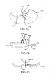
- Figs. 7A, 7B and 7C are various views of a distal portion of the meter housing which interfaces with the testers as they are dispensed.
- Fig. 8 provides a view of a cutaway portion of the cassette of Fig. 5 engaged within the meter of Figs. 4B-D.
- the subject packaged testers and methods of fabricating them are described first.
- a description of the subject cassettes and methods of using them with a physiological fluid meter is provided.
- a review of the kits of the present invention which include the packaged testers and/or the cassettes is provided.
- the present invention will be described in the context of analyte concentration measurement applications, and particularly in the context of glucose concentration in blood or interstitial fluid; however, such is not intended to be limiting and those skilled in the art will appreciate that the subject devices, systems and methods are useful in the measurement of other physical and chemical characteristics, e.g., blood coagulation time, blood cholesterol level, the existence of legal or illegal drugs, etc. of other biological substances, e.g., urine, saliva, etc.
- the strips of the present invention provide a plurality of testers.
- a general description of testers suitable for use with the present invention is provided.
- the testers may have a configuration similar to that of test strips used for analyte concentration determination, such as in the field of blood glucose monitoring.
- each tester includes a biosensor or sensor portion and an integrated microneedle or lancet. Electrochemical type sensors are most suitable for use with the present invention, however, other suitable types of sensor configurations may be used.
- Each tester includes two spaced-apart electrodes, a bottom electrode and a top electrode wherein at least one electrode is formed on an inert substrate material. Between the electrodes is an insulating space layer. The spacer layer has a cut-out portion which defines the reaction zone of the electrochemical biosensor containing a redox reagent system.
- the microneedle extends from a front end of and is planar with one of the electrodes.
- a channel is formed in the microneedle and a portion of the electrode from which extends, wherein fluid accessed within the skin, e.g., blood, interstitial fluid, other body fluids, is transported by the channel into the reaction zone of the electrochemical cell defined by the electrodes.
- fluid accessed within the skin e.g., blood, interstitial fluid, other body fluids
- Examples of such testers or test strip devices suitable for use with the present invention include those described in PCT Patent Application No. WO 96/72742/001 claiming priority to Great Britain Patent Application No. GB 0330929.4, EP-A-1 281 352, EP-A-1 284,121 and copending European application No. , claiming priority from USSN 10/143,399 filed 9th May 2002 [Attorney ref: P033762EP].
- the strips of the present invention provide a plurality of the above described testers in a serial arrangement where all of the testers are oriented in the same direction. In addition to such serial arrangement and unidirectional orientation, the subject strips are "continuous" over a suitable and practical length for achieving the objectives of the present invention.
- the testers and the associated strip are preferably fabricated by means of web-based processes wherein the resulting product is a collection of laminated layers of various materials.
- the testers are contiguous with the strip in that they are either affixed to a strip structure or are integrally fabricated with the strip structure, e.g. , a layer of the testers also serves as the strip structure.
- the strip structure includes a flexible frame which serves to interconnect the testers in a serial arrangement.
- the flexibility of the frame allows it to be folded or rolled upon itself for compact storage.
- the frame includes at least one planar surface, edge or ledge that extends the length of the strip and is integral with or affixed to each tester.
- the frame includes two planar edges which straddle the serially aligned testers and further includes a planar surface which bridges the two edges.
- the testers in a flat or unfolded or rolled condition, the testers substantially lie in the same plane as the frame.
- the testers are flexibly attached to or integral with the frame structure such that the testers are movable, flexible or bendable from the plane defined by the frame structure.
- the strip structure may further include a flexible packaging material which hermetically seals the strip to maintain the testers in a sterile condition prior to use.
- a flexible packaging material which hermetically seals the strip to maintain the testers in a sterile condition prior to use.
- Such packaging is also in the form of a strip or strips having length and width dimensions commensurate with that of the frame.
- two strips of packaging material are provided, which are heat sealed on either side of the strip structure and the associated test strips.
- the strip structure may further provide recesses or pockets within which the testers individually reside.
- the recess or pocket may be formed by the packaging material itself.
- the strip structures may be provided within a cassette which is configured to be engagable or loadable within a meter for analyzing the physiological fluid samples collected by the testers wherein the meter is configured to individually dispense the testers for use.
- the strip may itself be configured to be engagable or loadable within the meter.
- Figs. 1A, 1B, 2A and 2B there are shown two embodiments of the strips of testers of the present invention. While the construct of the two embodiments of strips are similar in that both provide a continuous serial arrangement of testers which are in a contiguous structure, there are differences.
- the embodiment of Figs. 1A and 1B provide for testers which are singulated from each other during the manufacturing process and then affixed to a separately fabricated strip structure.
- the strip embodiment of Figs. 2A and 2B provides for testers which are interconnected to each other by at least one webbing of material used to fabricate the testers, which webbing material serves to also form at least a portion of the strip structure or frame.
- Strip 2 of Figs. 1A and 1B provides a plurality of testers 4, as described above, which are singulated from each other and are individually positioned within a frame structure 6.
- each tester 4 has a sensor portion 16 and a microneedle or lancet 18 which extends from sensor portion 16.
- Strip 2 further includes a double-sided packaging, having a bottom, tray or recessed portion 8 and a top or cover portion which is not shown for purposes of illustration.
- Bottom portion 8 has a tray configuration within which is formed a plurality of recesses 10, otherwise referred to as blisters, pockets or cavities, having length, width and depth dimensions for accommodating or containing testers 4.
- the top portion of the packaging includes a thin flexible sheet of material and, when operatively affixed to tray 8, individually seals each of recesses 10.
- the packaging preserves the sterility of each recess 10, provides a moisture barrier for each recess, and prevents cross-contamination between recesses. Suitable packaging materials are discussed in greater detail below.
- Each recess 10 has a length in the range from about 1 to 50 mm and more typically from about 10 to 20 mm; a width in the range from about 1 to 30 mm and more typically from about 5 to 15 mm; and a thickness or depth in the range from about 100 to 3,000 ⁇ m and more typically from about 500 to 1,000 ⁇ m. While recesses 10 are illustrated and described as being rectangular, any suitable shape, e.g. , square, oval, elliptical, circular, etc., and configuration may be employed. Preferably, there is a one-to-one correspondence between the number of testers 4 and the number of recesses 10. Strip 2 may provide any number of testers 4 (and corresponding number of recesses 10) suitable for the application at hand. Typically, for monitoring glucose levels in a diabetic, for example, strip 2 may provide about 10 to 50 testers/recesses.
- each tester 4 is affixed to the recess 10 within which a tester 4 is contained.
- each tester 4 is flexible, bendable, deflectable or movable through the opening and to the outside of recess 10 about an axis defined by proximal end 12.
- Such range of motion is defined by an angle ⁇ (see Fig. 4) having a minimum range of motion no less than about 45°, and typically no less than about 60°.
- the bottom portion of the packaging material may be flexible or pre-scored to promote flexibility between recesses such that frame 6 and testers 4 are bendable or deflectable relative to each other.
- Frame 6 includes a planar surface defined around the opening of each recess 10. This planar surface defines a narrow margin 14 which extends between adjacent recesses 10 and defines a side edge or ledge 20 which extends the length of strip 2.
- Each bridge 14 is flexible about its longitudinal axis ( i.e. , along the width of strip 2) wherein adjacent testers are bendable about such an axis.
- Recesses 10 are preferably evenly spaced from each other along the length of strip 2.
- Figs. 2A and 2B illustrate another strip 30 of the present invention providing a frame 42 and plurality of testers 32 flexibly attached to frame 42.
- Each tester 32 has a sensor portion 34 and a microneedle or lancet 36, as described above.
- Testers 32 of strip 30 are interconnected to each other by at least one continuous web or layer of material, e.g. , an inert substrate material, a spacing layer, etc, from which testers 32 are made, or the interconnection may be provided by an additional layer which is not used to form testers 32.
- Such continuous web or layer of material defines frame 42 and includes segments 38 extending between or bridging adjacent testers 32.
- frame 42 has side rows 44 of holes 46.
- a spacing 40 is defined between each tester 32 and frame 42.
- Figs. 3A-3M there is shown certain steps of a web-based fabrication process for fabricating the strips of the present invention and, in particular, strip 2 and singulated testers 4 of Figs. 1A and 1B.
- strip 2 and singulated testers 4 of Figs. 1A and 1B.
- Those skilled in the art will appreciate the possible variations in these steps, or the addition or subtraction of one or more steps, in order to fabricate strip 30 and the interconnected testers 32 of Figs. 2A and 2B.
- the singulated testers 4 are fabricated in a side-to-side arrangement along the length of webbing
- the interconnected testers 32 are fabricated in an end-to-end arrangement along the length of webbing.
- Figs. 3A-3K For purposes of describing a web-based fabrication process of the present invention, only two testers are illustrated in Figs. 3A-3K; however, it is appreciated that any number of testers may be concurrently fabricated along the same length of webbing. Also, for purposes of describing the present invention, the same reference number (50) shall be throughout Figs. 3A-3K to identify the cumulative webbing structure which results from each successive step of the fabrication process.
- the fabrication process is initiated by providing a continuous webbing of substrate material 51 upon which a first conductive layer 52 is provided to form a first electrode, collectively forming a cumulative webbing structure 50.
- the substrate webbing 51 preferably consists of a polymer film, a foil material and/or inorganic materials such as silicon, glass, ceramic and the like.
- a suitable polymer for example, is polyester, e.g. , polyethylene terephthalate (PET).
- Conductive layer 52 may be provided by any one of a variety of techniques including, but not limited to, vacuum sputtering, evaporation techniques, e.g. , electron beam evaporation, filament evaporation, etc.), electroplating, electroless plating, screen printing and the like.
- Suitable conductive materials include, but are not limited to, palladium, gold, platinum, silver, iridium, stainless steel and the like, or a metal oxide, such as carbon, e.g. , conductive carbon ink, or doped tin oxide; however, for purposes of describing the present invention, palladium is used as conductive layer 52.
- a redox reagent system 54 is deposited within a reaction zone 56 of palladium layer 52 along the length of webbing structure 50. Such deposition may be accomplished with slot coating, needle coating, screen printing or ink jet printing techniques, which are well known in the art.
- a spacer layer webbing 58 as shown in Fig. 3B, is provided having a spacer layer of which both surfaces have an adhesive layer applied thereto. These three layers are collectively sandwiched between bottom and top protective release liners.
- the resulting 5-layer spacer webbing 58 is then selectively "kiss" cut so as only to cut through portions of the top release liner, the adhesive layers and the spacer layer, but not through the bottom release liner.
- the portions of the top release liner and the adhesive layers which are cut free are removed from spacer webbing 58, as illustrated in Fig. 3B, what remains are the exposed portions 60 (the hatched areas) of the adhesive layers and the bottom release liner.
- the top side or surface of the resulting spacer layer webbing 58 is then applied over the reagent zone 56 of webbing structure 50, adhering thereto by means of the exposed areas 60 of the bottom adhesive.
- cumulative webbing structure 50 is then selectively die cut completely through its various web layers, i.e. , bottom release liner (now the top layer of cumulative webbing structure 50), adhesive layer and palladium layer 52. Specifically, the front or forward portion 64 of webbing structure 50 is cutaway to prepare webbing structure 50 for receiving the microneedle webbing. Additionally, a scrap piece 66 is cutaway from each tester The cut out portions 64 and 66 are then removed from webbing structure 50 and scrapped. Next, the remaining release liner 68 is peeled away from webbing structure 50 and discarded, as shown in Fig. 3E.
- a webbing of conductive material 70 is provided and die cut to form the second electrode layer 72 and microneedles 74.
- Conductive material webbing 70 may include any of the conductive materials used above for fabricating the first conductive layer 52; however, for purposes of describing the invention, gold-plated stainless steel is used.
- conductive material webbing 70 is then placed on top of cumulative webbing structure 50, which structure now includes a substrate material 51 on the bottom thereof, and palladium layer 52 having a reagent thereon, the previously exposed, remaining adhesive layer 60, spacer creating layer 62 and gold-plated stainless steel layer 72, successively stacked thereon.
- Figs. 3H and 3I several die cuts are made to cumulative webbing structure 50.
- bridges 76 formed by the gold-plated stainless steel layer 72 are die cut and scrapped. Cutting bridges 76 also frees piece 78 of layer 72 which is also scraped.
- a die cut is made to remove two scrap pieces 82 on opposing sides of reaction area 84 to provide a venting port within the electrochemcial cell and to define an exact volume for sample collection and a precise electrode surface area.
- cumulative webbing structure 50 is cut across its width between adjacent testers, resulting in a plurality of singulated testers 86 and 88.
- the bottom or tray portion of the packaging strips of the present invention is preferably made of flexible material but may be rigid instead. Suitable materials include plastics, e.g. , high-density polyethylene, having an external surface formed of aluminum foil-plastic laminate integrally bonded to the plastic tray.
- the tray structure including recess cavities 90 and the planar surfaces around the recess openings, may be formed by compressing the material between matched dies. The tray structure may be.
- the entire strip is placed on top of the bottom portion of the packaging, wherein each tester is centrally aligned with a recess.
- a desiccant material 92 is disposed on, and preferably adhered to, each tester at a location that will not interfere with the sensor and miconeedle functions.
- the desiccant material 92 helps to maintain each recess at an appropriate humidity level after packaging so that the sensor chemistry is not adversely affected prior to use. Because the recesses, as described below, are hermetically isolated from each other, the opening of one recess will not affect the hermetically sealed state of the other recesses.
- the desiccant material may have any suitable form, including but not limited to a disk or bead configuration.
- each tester is attached to and subsequently retained within the interior of the recess in which it is positioned.
- the testers are attached by means of sonic welding, an adhesive material, or the like, as it is intended that each tester be permanently retained within or associated with the recesses to which it is attached for the operative life of the tester.
- a top portion (not shown) of packaging 88 is provided which has length and width dimensions commensurate or similar with that of the bottom portion of packaging 88 and may be made of materials similar to that of the bottom portion of the packaging, such as a plastic laminate having aluminum liner.
- the top portion is then aligned on the top of bottom or recess portion of packaging 88 and heat sealed therewith along the perimeters of each recess, thereby forming a laminated packaged strip having a plurality of sealed recesses encased in a moisture and sterility barrier.
- sprocket holes 98 are die cut on both edges of the packaged strip.
- the resulting packaged strip is now ready for operative loading into a cassette or cartridge of the present invention, which will now be described in detail.
- the subject strips may be configured to be loaded within a cassette which is configured to be loaded within a meter for analyzing physiological fluids.
- the meter is configured to receive the cassette and provided with a mechanism which engages with and indexes the strip.
- the strip is provided with sprocket holes to engage with a pair of indexing rollers within the meter which are configured to index and dispense only a single tester at a time upon activation of the meter by the user.
- the indexing and dispensing of the flexibly attached testers involves peeling back the packaging material, if such is provided, and moving the tester in a manner and into a position for piercing the skin surface.
- System 100 includes a cassette or cartridge 102 and a meter 104.
- Cassette 102 contains a strip 106 of testers (see Fig. 4B), as described above with respect to Figs. 1A, 1B, 2A, 2B and 3K, operatively loaded therein.
- Cassette 102 and meter 104 are configured to operatively engage with each other wherein meter 104 functions to individually dispense testers of strip 106 from cassette 102 and to measure one or more characteristics, e.g., one or more analyte concentrations, of the body fluid sampled by a dispensed tester.
- characteristics e.g., one or more analyte concentrations
- Cassette 102 has a modular configuration and may be replaced and disposed of upon use of all testers contained within cassette 102. Additionally, cassette 102 is configured in any convenient manner to accommodate a strip 106 of the present invention containing a plurality of testers. The number of testers within a single strip or loop is sufficiently large, e.g. , between about 10 and 100, and more typically between about 10 and 50, so as to minimize the frequency with which the user must replace the cassette, and preferably, not so numerous such that the testers' effectiveness expires prior to being used.
- Cassette 102 may contain a barcode or some other means (such as a chip) for transferring information to meter 104 upon operatively engaging loading the cassette with the meter. As such, meter 104 would automatically read this information when cassette 102 via a detection system. Any conventional detector may be employed. Information that may be useful includes: a calibration factor or code for calibrating the meter according to the type of testers employed within the cassette, the number of testers used and/or remaining within the cassette, the number of days since the cassette was installed and/or days until tester expiration. The latter information is important as the testers (within a packaged strip) have a limited lifetime.
- Cassette housing 102 is preferably light-weight, ergonomically designed and small enough to be handled by the user with one hand, but which is spacious enough internally to accommodate strip 106 as well as testers which have been used (in operation with the meter) and the associated packaging material from such used testers.
- One useful cassette configuration is illustrated in Fig. 5. This configuration provides an internal construct having a set of curvilinear tracks or grooves 108, 110 and 113 defined and separated by walls 114, which run substantially parallel to each other in a wound or spooled configuration. The tracks have width dimensions to accommodate the thickness of a strip recess and a wall height to accommodate the strips' width. Walls 114 are sandwiched between two sides of housing 112.
- Such a design is preferably made of a plastic material, such as ABS or any other suitable thermoplastic, and fabricated by injection molding techniques.
- the tracks originate from a centralized area of cassette 102 and terminate at a peripheral portion of cassette 102 at a pair of drive rollers 118 and 120.
- a first or central track 108 runs between second or inside track 110 and third or outside track 113.
- Central track 108 is used to accommodate a packaged strip 106, which is preferably pre-loaded within cassette 102 during the manufacturing assembly process.
- Central track 108 terminates at a spacing or throat 116 between internal cylindrically-shaped drive rollers 118 and 120. The distance between drive rollers 118 and 120 which define margin or dispensing space 116 is sufficient to snugly accommodate the thickness of a packaged recess of strip 106 there through without compressing the recess, so as not to cause damage to the tester therein. As shown in Fig.
- drive roller 118 is axially engaged through housing 108 of cassette 102 with a drive gear 152 positioned on the backside 150 of cassette 102.
- Drive gear 152 has teeth 154 for engagement with internal componentry of meter 104, described in greater detail below, for rotating drive roller 118.
- drive roller 118 rotates drive roller 120 by sprocket pins in the direction of arrow 122b by means of sprocket pins (not shown) which extend radially from roller 118 into corresponding pin recess (not shown) within roller 120.
- both rollers may provide pins and recesses which correspond to the recesses and pin, respectively.
- each of rollers 118 and 120 have radially-extending sprockets 164 which are each sized and spaced apart from each other an equidistance to matingly engage with holes 166 of packaged strip 106.
- sprockets 164 mate with holes 166 and cause packaged strip 106 to be indexed or advanced in the direction of arrow 128a (also shown in Fig. 5).
- indexing it is meant that the strip is caused to advance only a fixed distance and expose and dispense only a single tester upon activation of the meter's mechanics to perform a fluid sampling and measurement routine. Such indexing routine and the corresponding meter mechanics will be described in greater detail below.
- the resulting indexing motion causes the strip packaging to pull apart or separate wherein the bottom or recess portion 168 of the packaging remains engaged with roller 118 and is caused to advance in the direction of arrow 128b and wherein the top or cover portion 126 portion remains engaged with roller 120 and is caused to advance in the direction of arrow 128c.
- tester 130a becomes exposed as it passes through rollers 118 and 120 and is flexed away from its recess, extends downward in a direction substantially perpendicular to the rotation of rollers 118 and 120 and substantially normal to the skin surface.
- tester 130a In this distally extended or dispensed position, tester 130a is in a testing or active position wherein microneedle 172 is caused to penetrate the skin and access the targeted physiological fluid therein and the electrode contacts 174 of tester 130a are positioned to contact corresponding electrical contacts of meter 104, which will be discussed in greater detail below with respect to Figs. 7 and 8.
- each successive indexing routine advances the most recently used tester along with bottom packaging portion 168, as illustrated by tester 130b of Figs. 5 and 6.
- tester 130c of Figs. 5 and 6.
- meter 104 includes an upper body portion 130 and a lower body portion 132, the latter of which may be covered by a protective cap (not shown) when not in use, and is exposed upon removal of the cap.
- Upper body portion 130 provides a display screen 136 and various knobs 138 and buttons 140 for user control and operation of meter 104. Additional buttons may be provided to allow the user to interact with the meter, e.g. , scroll through data, set time and date, etc.
- Display screen 136 may be used to display various user directions, system messages and data, e.g.
- the backside 146 of upper body portion 130 includes an open receptacle or cavity 148 configured and dimensioned for receiving cassette 102. As shown in Fig. 4C, receptacle 148 includes a geared tooth rack 156 having drive teeth 158 which engage with gear teeth 154 of drive wheel 152.
- Lower portion 132 of meter 104 includes a distal housing face 142 having a distally extending "pressure ring" 144 which, when applied to the target skin surface, depresses tissue around a periphery of the intended access site within the skin. All or at least a distal housing face 142 of lower portion 132 is preferably transparent so as to allow the user to observe the target skin site during the testing process. Various views of distal face 142 are illustrated in Figs. 7A-7C and 8. Within pressure ring 144 is a slot 180 through which the microneedle 172 of a dispensed tester extends when in a testing or active position, as illustrated in Figs. 7C and 8. As best shown in Fig.
- distal housing face further includes a set of electrical contacts or leads 184a and 184b which extend from the meter's electronics which are housed in upper portion 130.
- Such electronics typically include a controller in the form of a microprocessor for controlling all electronic related system functions, including but not limited to, displaying information, receiving data input by the user, implementing user commands, the testing of the physiological fluid (e.g. , sending the necessary electrical signals to the tester), receiving calibration information from the cassette, storing system software and information into memory, etc.
- Electrical contacts 184 are aligned to engage with the corresponding electrodes or electrode contacts of the testers. As such, input signals are provided to and output signals are received from the tester's sensor for testing, for example, the analyte concentration of the sampled fluid.
- the methods of the present invention involve the use of meter cassette 102 and meter 104.
- the user begins by depressing button 140, as illustrated in Figs. 4B, 4C and 4D, to unlock a locking mechanism (not shown) which maintains upper portion 130 and lower portion 132 in a locked position when meter 104 is not in use to prevent inadvertent activation of the meter.
- Depression of button 140 could also serve to turn on the meter's electronics.
- lower portion 132 In operation, lower portion 132 is slidingly received by upper portion 130. Thus, when distal face 142 of lower body portion 132 is pressed against the skin, lower portion 132 moves in the direction of arrow 145 of Fig. 4D while being resisted by a spring (not shown) within the meter.
- the load of the spring may be adjustable to accommodate various test locations on the body and the needs of different users.
- Another spring mechanism which has become loaded or energized by this relative motion, is unlatched thereby forcing cassette 102 to move downward within meter 104.
- gear drive 152 of cassette 102 (see Fig.
- Tester 130a is then optimally oriented to contact electrode contacts 184a and 184b of distal housing face 142 of meter 104, as illustrated in Fig. 7C, and to penetrate the skin with microneedle 172. If for some reason, lower portion 132 does not travel the predetermined distance, i.e., the user fails to complete the necessary actuation of meter 104, the packaging encasing unused tester 130a will remain sealed so as not to expose it to contaminants. Concurrently with the dispensing of unused tester 130a, the last used tester 130b is caused to rotate with drive roller 118 and fold back into its corresponding recess of strip 106 and fed along with it into track 113.
- the penetration depth of microneedle 172 is preferably set to between about 0.02 mm and 2.0 mm, or more preferably set between 0.5 mm and 1.5 mm.
- pressure ring 144 results at least in part from stretching the skin in this area and thereby helps to extract a sample from the skin and "pump" it into the fluid transfer channel within microneedle 172.
- the sampled fluid is then transferred to the sensor portion of tester 130awherein an electrochemical assay is made, and the results displayed on display screen 136 of meter 104.
- meter 104 may be configured to display a "sample received" icon to indicate to the user that a sufficient volume of fluid has been collected and the meter may now be removed from the test site.
- tester 130a is caused to advance around roller 118 and returned to a seated position within its corresponding recess, while the next unused tester is operatively dispensed.
- the used portion of strip 106 advances through tracks 110 and 113, and is caused to be spooled within cassette 102 until all testers are used.
- the completely used cassette 102 is removed from meter 104 and may be disposed of without concern of creating a biohazard.
- a cassette containing a partially used strip of testers may be removed from the meter and later engaged to use the remaining unused testers.
- kits for practicing the subject methods include a subject system for practicing the subject invention.
- the subject system includes a subject meter and at least one subject cassette which may be disposable and replaceable.
- the subject cassette may be pre-loaded with a strip of testers as described above or may be provided.
- the kit may include one or more strips to be loaded into the cassette.
- the kits typically include instructions for using the subject systems and for loading and removing cassettes into and out of the subject meters. These instructions may be present on one or more of the packaging, a label insert, containers present in the kits, and the like.
Abstract
Description
- This invention relates to the sampling and testing of physiological fluid. More particularly, the invention relates to continuous strips of physiological fluid sampling and testing devices, the manufacturing thereof and the use thereof within a meter configured for individually dispensing such sampling and testing devices.
- Analyte concentration determination in physiological samples is of ever increasing importance to today's society. Such assays find use in a variety of application settings, including clinical laboratory testing, home testing, etc., where the results of such testing play a prominent role in the diagnosis and management of a variety of disease conditions. Analytes of interest include glucose for diabetes management, cholesterol for monitoring cardiovascular conditions, drugs for monitoring levels of therapeutic agents, and identifying illegal levels of drugs, and the like. In response to this growing importance of analyte concentration determination, a variety of analyte concentration determination protocols and devices for both clinical and home testing have been developed.
- In determining the concentration of an analyte in a physiological sample, a physiological sample must first be obtained. Obtaining and testing the sample often involves cumbersome and complicated procedures. Unfortunately, successful manipulation and handling of test elements, such as test strips, lancing members, meters and the like is to a great extent dependent on the visual acuity and manual dexterity of the user, which in the case of people with diabetes is subject to deterioration over the course of the disease state. In extreme cases people that have significant loss of sight and sensation, testing procedures can become significantly difficult and requires additional assistance from ancillary devices or personnel.
- A typical procedure for making a glucose measurement with the use of a - test strip involves the following actions or steps (but not necessarily in the order given): (1) removing supplies from a carrying case, (2) removing a lancing device loading cap or door, (3) removing and disposing of a used lancet from the lancing device, (4) inserting the lancet in the lancing device, (5) twisting off a protective cap from the lancet, (6) replacing the lancing device cap, (7) cocking the lancing device, (8) opening a test strip vial/ container, (9) removing a strip from the container and inserting or interfacing it with a meter, (10) holding a lancing device to the skin, (11) firing the lancing device, (12) removing the lancing device from the skin, (13) extracting a sample, (14) applying sample to the test strip and obtaining results of the measurement; (15) disposing of the test strip, (16) cleaning the test site, and (17) returning supplies to the carrying case. Of course, certain glucose measurement systems and protocols may involve fewer or more steps.
- One manner of reducing the number of actions is by the use of integrated devices which combine multiple functions in order to minimize the handling of sensor and/or lancing components which may lead to contamination of the components and /or injury to the user. In this regard, certain test strip dispensers are configured to both store and advance successive test strips upon actuation. Examples of such devices are presented in U.S. Patent Nos. 5,510,266; 5,660,791; 5,575,403; 5,736,103; 5,757,666; 5,797,693; 5,856,195 and PCT Publication WO 99/44508. Some of these test strip dispensers devices also include meter functionality for testing physiologic fluid.
- Another class of devices designed to decrease the number of steps required in test strip use includes automatic or semi-automatic lancing devices. U.S. Patent No. 6,228,100 discloses a structure configured for sequential firing of a number of lancets, one at a time, in order to eliminate the requirement that a user remove and replace each lancet individually before and after use. However, this device does not include any sensor components or functions. While other systems, such as those described in U.S. Patent Nos. 6,352,514; 6,332,871; 6,183,489; 6,099,484; 6,056,701 and 5,820,570, integrate the test strip and lancing functions within a single device, the test strip and lancet are separate components which must be loaded into the meter or dispenser individually.
- The device disclosed in U.S. Patent No. 5,971,941 attempts to combine the functionality of each of the preceding classes of test strip devices. In effort to provide an "integrated" system for sampling blood and analysis thereof, it includes a magazine of test strips, test strip advancement and dispensing features, a meter with a display and an automated lancing mechanism all housed within a single box. While presenting some measure of improvement in user convenience, the test strip and lancing features are independent from each other causing the user to take two steps in lancing and transferring sample to a test strip.
- WO 02/49507 discloses a meter including a microneedle which extracts fluid from a subject and is selectively switched between multiple sensor elements. While offering a slight improvement over prior devices, such configurations typically require complex componentry which can be difficult to operate and are costly to produce. Further, the more componentry and moving parts within a device, the more questionable the reliability of the device.
- Technological advancements have been made in test strip fabrication where both sensor and lancing functions and structures are provided on a single test strip. Certain web-based methods have been used to make such fully integrated test strips which are singulated after fabrication prior to being collectively packaged in a cartridge, magazine, cassette or the like. While such test strips packaging reduces, to some degree, the necessary handling by a user, this modality still requires additional manufacturing and packaging steps.
- While many of the above-described devices and other similar devices involve changing-out spent test strips and/or lancet members one-at-a-time, such as those described in U.S. Patent Nos. 6,027,459; 6,063,039; 6,071,251 and 6,283,926 as well as for certain embodiments disclosed in PCT Publication WO 01/64105, certain other devices provide means for ejecting a used step strip or dispensing it into a receptacle within the device. Still other devices provide for multiple lancet/sensor pairs that only need to be changed out after all of the test strip and/or lancet members within a cartridge or cassette are used.
- As such, there is continued interest in the development of new devices and methods for use in test strip dispensing. Of particular interest would be the development of such devices and methods which are easy and inexpensive to manufacture, have minimal components, are portable and easy to use, particularly for visually and dextrally impaired individuals, and involve no direct contact and minimal handling by the user, thereby minimizing the risk of injury to the user and damage and/or contamination to the test strip devices contained therein.
- Of course, such advantages may be present in the devices and systems of the present invention in various degrees. It is intended that, in one way or another, the invention is of assistance in reducing barriers to patient self-monitoring and therefore result in improved outcomes in the management of disease, such as diabetes.
- The present invention provides continuous strips of testers in an individually-sealed packaging which maintains the testers in a sterile condition until used. The subject testers include a test strip sensor integrated with a microneedle for accessing and collecting a sample of physiological fluid and for measuring a chemical characteristic, such as target analyte concentration, of the sampled fluid. The present invention further provides cassettes of the subject strips for removable engagement with a meter for individually dispensing the testers and for facilitating the analysis of the sampled fluid. Also provided by the present invention are systems which include the subject strips and cassettes and such a meter. Methods of using the strips and cassettes are also provided, along with kits for practicing the subject methods.
- An aspect of the present invention is to provide devices and methods for facilitating a user in the self-testing of analyte concentrations, such blood glucose levels. More particularly, such devices facilitate the easy, convenient and safe dispensing of testers for the measuring of analyte concentrations and the subsequent storage of such testers after they have been used.
- These and other objects, advantages, and features of the invention will become apparent to those persons skilled in the art upon reading the details of the methods and systems of the present invention which are more fully described below.
- To facilitate understanding, the same reference numerals have been used (where practical) to designate similar elements that are common to the Figures. Some such numbering has, however, been omitted for the sake of drawing clarity.
- Fig. 1A is a planar view of one embodiment of according to the present invention of a strip of singulated testers. Fig. 1B is a side view of the strip of Fig. 1A taken along the line B-B.
- Fig. 2A is a planar view of another embodiment according to the present invention of a strip of interconnected testers. Fig. 2B is a side view of the strip of Fig. 2A taken along the line B-B.
- FigS. 3A-3K illustrate various steps of a continuous web-based method of the present invention for fabricating the strip of testers of Figs. 1A and 1B.
- Fig. 4A is an isometric view of a cassette of the present invention for storing a strip of testers of the present invention.
- Fig. 4B is an isometric view of the front side of a meter of the present invention for use with the cassette of Fig. 4A.
- Fig. 4C is an isometric view of the cassette of Fig. 4A in the process of engagement with the meter of Fig. 4B.
- Fig. 4D is an isometric view of the cassette of Fig. 4A fully engaged within the meter of Fig. 4B.
- Fig. 5 is a cross-sectional planar view of the cassette of Fig. 4A.
- Fig. 6 illustrates a strip of testers operatively engaged with a portion of the internal componentry of a cassette of the present invention.
- Figs. 7A, 7B and 7C are various views of a distal portion of the meter housing which interfaces with the testers as they are dispensed.
- Fig. 8 provides a view of a cutaway portion of the cassette of Fig. 5 engaged within the meter of Figs. 4B-D.
- Before the present invention is described in such detail, it is to be understood that this invention is not limited to particular variations set forth herein as various changes or modifications may be made to the invention described and equivalents may be substituted without departing from the true spirit and scope of the invention. In addition, many modifications may be made to adapt a particular situation, material, composition of matter, process, process act(s) or step(s) to the objective(s), spirit or scope of the present invention. All such modifications are intended to be within the scope of the claims made herein.
- Methods recited herein may be carried out in any order of the recited events which is logically possible, as well as the recited order of events. Furthermore, where a range of values is provided, it is understood that every intervening value, between the upper and lower limit of that range and any other stated or intervening value in that stated range is encompassed within the invention. Also, it is contemplated that any optional feature of the inventive variations described may be set forth and claimed independently, or in combination with any one or more of the features described herein.
- All existing subject matter mentioned herein (e.g., publications, patents, patent applications and hardware) is incorporated by reference herein in its entirety except insofar as the subject matter may conflict with that of the present invention (in which case what is present herein shall prevail). The referenced items are provided solely for their disclosure prior to the filing date of the present application. Nothing herein is to be construed as an admission that the present invention is not entitled to antedate such material by virtue of prior invention.
- Reference to a singular item, includes the possibility that there are plural of the same items present. More specifically, as used herein and in the appended claims, the singular forms "a," "and," "said" and "the" include plural referents unless the context clearly dictates otherwise. It is further noted that the claims may be drafted to exclude any optional element. As such, this statement is intended to serve as antecedent basis for use of such exclusive terminology as "solely," "only" and the like in connection with the recitation of claim elements, or use of a "negative" limitation. Last, it is to be appreciated that unless defined otherwise, all technical and scientific terms used herein have the same meaning as commonly understood by one of ordinary skill in the art to which this invention belongs.
- In further describing the subject invention, the subject packaged testers and methods of fabricating them are described first. Next, a description of the subject cassettes and methods of using them with a physiological fluid meter is provided. Finally, a review of the kits of the present invention which include the packaged testers and/or the cassettes is provided.
- In the following description, the present invention will be described in the context of analyte concentration measurement applications, and particularly in the context of glucose concentration in blood or interstitial fluid; however, such is not intended to be limiting and those skilled in the art will appreciate that the subject devices, systems and methods are useful in the measurement of other physical and chemical characteristics, e.g., blood coagulation time, blood cholesterol level, the existence of legal or illegal drugs, etc. of other biological substances, e.g., urine, saliva, etc.
- As mentioned above, the strips of the present invention provide a plurality of testers. Prior to a detailed discussion of the strip devices of the present invention, a general description of testers suitable for use with the present invention is provided.
- The testers may have a configuration similar to that of test strips used for analyte concentration determination, such as in the field of blood glucose monitoring. As used with the present invention, each tester includes a biosensor or sensor portion and an integrated microneedle or lancet. Electrochemical type sensors are most suitable for use with the present invention, however, other suitable types of sensor configurations may be used. Each tester includes two spaced-apart electrodes, a bottom electrode and a top electrode wherein at least one electrode is formed on an inert substrate material. Between the electrodes is an insulating space layer. The spacer layer has a cut-out portion which defines the reaction zone of the electrochemical biosensor containing a redox reagent system. The microneedle extends from a front end of and is planar with one of the electrodes. A channel is formed in the microneedle and a portion of the electrode from which extends, wherein fluid accessed within the skin, e.g., blood, interstitial fluid, other body fluids, is transported by the channel into the reaction zone of the electrochemical cell defined by the electrodes. Examples of such testers or test strip devices suitable for use with the present invention include those described in PCT Patent Application No. WO 96/72742/001 claiming priority to Great Britain Patent Application No. GB 0330929.4, EP-A-1 281 352, EP-A-1 284,121 and copending European application No. , claiming priority from
USSN 10/143,399 filed 9th May 2002 [Attorney ref: P033762EP]. - The strips of the present invention provide a plurality of the above described testers in a serial arrangement where all of the testers are oriented in the same direction. In addition to such serial arrangement and unidirectional orientation, the subject strips are "continuous" over a suitable and practical length for achieving the objectives of the present invention. The testers and the associated strip are preferably fabricated by means of web-based processes wherein the resulting product is a collection of laminated layers of various materials. The testers are contiguous with the strip in that they are either affixed to a strip structure or are integrally fabricated with the strip structure, e.g., a layer of the testers also serves as the strip structure.
- The strip structure includes a flexible frame which serves to interconnect the testers in a serial arrangement. The flexibility of the frame allows it to be folded or rolled upon itself for compact storage. The frame includes at least one planar surface, edge or ledge that extends the length of the strip and is integral with or affixed to each tester. Most commonly, the frame includes two planar edges which straddle the serially aligned testers and further includes a planar surface which bridges the two edges. As such, in a flat or unfolded or rolled condition, the testers substantially lie in the same plane as the frame. The testers are flexibly attached to or integral with the frame structure such that the testers are movable, flexible or bendable from the plane defined by the frame structure.
- The strip structure may further include a flexible packaging material which hermetically seals the strip to maintain the testers in a sterile condition prior to use. Such packaging is also in the form of a strip or strips having length and width dimensions commensurate with that of the frame. In certain embodiments, two strips of packaging material are provided, which are heat sealed on either side of the strip structure and the associated test strips. Additionally, the strip structure may further provide recesses or pockets within which the testers individually reside. In certain embodiments, the recess or pocket may be formed by the packaging material itself.
- The strip structures, with or without the packaging, may be provided within a cassette which is configured to be engagable or loadable within a meter for analyzing the physiological fluid samples collected by the testers wherein the meter is configured to individually dispense the testers for use. Alternatively, the strip may itself be configured to be engagable or loadable within the meter.
- Referring now to the Figures and to Figs. 1A, 1B, 2A and 2B in particular, there are shown two embodiments of the strips of testers of the present invention. While the construct of the two embodiments of strips are similar in that both provide a continuous serial arrangement of testers which are in a contiguous structure, there are differences. The embodiment of Figs. 1A and 1B provide for testers which are singulated from each other during the manufacturing process and then affixed to a separately fabricated strip structure. Conversely, the strip embodiment of Figs. 2A and 2B provides for testers which are interconnected to each other by at least one webbing of material used to fabricate the testers, which webbing material serves to also form at least a portion of the strip structure or frame.
- Strip 2 of Figs. 1A and 1B provides a plurality of
testers 4, as described above, which are singulated from each other and are individually positioned within aframe structure 6. As mentioned, eachtester 4 has asensor portion 16 and a microneedle orlancet 18 which extends fromsensor portion 16. Strip 2 further includes a double-sided packaging, having a bottom, tray or recessedportion 8 and a top or cover portion which is not shown for purposes of illustration.Bottom portion 8 has a tray configuration within which is formed a plurality ofrecesses 10, otherwise referred to as blisters, pockets or cavities, having length, width and depth dimensions for accommodating or containingtesters 4. The top portion of the packaging includes a thin flexible sheet of material and, when operatively affixed totray 8, individually seals each ofrecesses 10. As such, the packaging preserves the sterility of eachrecess 10, provides a moisture barrier for each recess, and prevents cross-contamination between recesses. Suitable packaging materials are discussed in greater detail below. - Each
recess 10 has a length in the range from about 1 to 50 mm and more typically from about 10 to 20 mm; a width in the range from about 1 to 30 mm and more typically from about 5 to 15 mm; and a thickness or depth in the range from about 100 to 3,000 µm and more typically from about 500 to 1,000 µm. Whilerecesses 10 are illustrated and described as being rectangular, any suitable shape, e.g., square, oval, elliptical, circular, etc., and configuration may be employed. Preferably, there is a one-to-one correspondence between the number oftesters 4 and the number ofrecesses 10. Strip 2 may provide any number of testers 4 (and corresponding number of recesses 10) suitable for the application at hand. Typically, for monitoring glucose levels in a diabetic, for example, strip 2 may provide about 10 to 50 testers/recesses. - The
proximal end 12 of eachtester 4 is affixed to therecess 10 within which atester 4 is contained. As such, when the recess is not covered or sealed, eachtester 4 is flexible, bendable, deflectable or movable through the opening and to the outside ofrecess 10 about an axis defined byproximal end 12. Such range of motion is defined by an angle α (see Fig. 4) having a minimum range of motion no less than about 45°, and typically no less than about 60°. Alternatively or additionally, the bottom portion of the packaging material may be flexible or pre-scored to promote flexibility between recesses such thatframe 6 andtesters 4 are bendable or deflectable relative to each other. -
Frame 6 includes a planar surface defined around the opening of eachrecess 10. This planar surface defines anarrow margin 14 which extends betweenadjacent recesses 10 and defines a side edge orledge 20 which extends the length of strip 2. Eachbridge 14 is flexible about its longitudinal axis (i.e., along the width of strip 2) wherein adjacent testers are bendable about such an axis.Recesses 10 are preferably evenly spaced from each other along the length of strip 2. Along each side or edge 20 of strip 2 and extending the length of strip 2 is arow 24 of evenly spaced, serially aligned sprocket holes 22 for receiving drive sprockets of a drive wheel, discussed in greater detail below. - Figs. 2A and 2B illustrate another
strip 30 of the present invention providing aframe 42 and plurality oftesters 32 flexibly attached to frame 42. Eachtester 32 has asensor portion 34 and a microneedle orlancet 36, as described above.Testers 32 ofstrip 30 are interconnected to each other by at least one continuous web or layer of material, e.g., an inert substrate material, a spacing layer, etc, from whichtesters 32 are made, or the interconnection may be provided by an additional layer which is not used to formtesters 32. Such continuous web or layer of material definesframe 42 and includessegments 38 extending between or bridgingadjacent testers 32. As described above with respect toframe 6,frame 42 hasside rows 44 ofholes 46. A spacing 40 is defined between eachtester 32 andframe 42. - Referring now to Figs. 3A-3M, there is shown certain steps of a web-based fabrication process for fabricating the strips of the present invention and, in particular, strip 2 and
singulated testers 4 of Figs. 1A and 1B. Those skilled in the art will appreciate the possible variations in these steps, or the addition or subtraction of one or more steps, in order to fabricatestrip 30 and theinterconnected testers 32 of Figs. 2A and 2B. For example, while thesingulated testers 4 are fabricated in a side-to-side arrangement along the length of webbing, theinterconnected testers 32 are fabricated in an end-to-end arrangement along the length of webbing. - For purposes of describing a web-based fabrication process of the present invention, only two testers are illustrated in Figs. 3A-3K; however, it is appreciated that any number of testers may be concurrently fabricated along the same length of webbing. Also, for purposes of describing the present invention, the same reference number (50) shall be throughout Figs. 3A-3K to identify the cumulative webbing structure which results from each successive step of the fabrication process.
- The fabrication process is initiated by providing a continuous webbing of
substrate material 51 upon which a firstconductive layer 52 is provided to form a first electrode, collectively forming acumulative webbing structure 50. Thesubstrate webbing 51 preferably consists of a polymer film, a foil material and/or inorganic materials such as silicon, glass, ceramic and the like. A suitable polymer, for example, is polyester, e.g., polyethylene terephthalate (PET).Conductive layer 52 may be provided by any one of a variety of techniques including, but not limited to, vacuum sputtering, evaporation techniques, e.g., electron beam evaporation, filament evaporation, etc.), electroplating, electroless plating, screen printing and the like. Suitable conductive materials include, but are not limited to, palladium, gold, platinum, silver, iridium, stainless steel and the like, or a metal oxide, such as carbon, e.g., conductive carbon ink, or doped tin oxide; however, for purposes of describing the present invention, palladium is used asconductive layer 52. Thereafter, as shown in Fig. 3A, aredox reagent system 54 is deposited within areaction zone 56 ofpalladium layer 52 along the length ofwebbing structure 50. Such deposition may be accomplished with slot coating, needle coating, screen printing or ink jet printing techniques, which are well known in the art. - In an ancillary web-based process, a
spacer layer webbing 58, as shown in Fig. 3B, is provided having a spacer layer of which both surfaces have an adhesive layer applied thereto. These three layers are collectively sandwiched between bottom and top protective release liners. The resulting 5-layer spacer webbing 58 is then selectively "kiss" cut so as only to cut through portions of the top release liner, the adhesive layers and the spacer layer, but not through the bottom release liner. The portions of the top release liner and the adhesive layers which are cut free are removed fromspacer webbing 58, as illustrated in Fig. 3B, what remains are the exposed portions 60 (the hatched areas) of the adhesive layers and the bottom release liner. Finally, as illustrated in Fig. 3C, the top side or surface of the resultingspacer layer webbing 58 is then applied over thereagent zone 56 ofwebbing structure 50, adhering thereto by means of the exposedareas 60 of the bottom adhesive. - As illustrated in Fig. 3D,
cumulative webbing structure 50 is then selectively die cut completely through its various web layers, i.e., bottom release liner (now the top layer of cumulative webbing structure 50), adhesive layer andpalladium layer 52. Specifically, the front or forward portion 64 ofwebbing structure 50 is cutaway to preparewebbing structure 50 for receiving the microneedle webbing. Additionally, ascrap piece 66 is cutaway from each tester The cut outportions 64 and 66 are then removed from webbingstructure 50 and scrapped. Next, the remainingrelease liner 68 is peeled away from webbingstructure 50 and discarded, as shown in Fig. 3E. - In another ancillary web-based process, as illustrated in Fig. 3F, a webbing of
conductive material 70 is provided and die cut to form thesecond electrode layer 72 andmicroneedles 74.Conductive material webbing 70 may include any of the conductive materials used above for fabricating the firstconductive layer 52; however, for purposes of describing the invention, gold-plated stainless steel is used. As illustrated in Fig. 3G,conductive material webbing 70 is then placed on top ofcumulative webbing structure 50, which structure now includes asubstrate material 51 on the bottom thereof, andpalladium layer 52 having a reagent thereon, the previously exposed, remainingadhesive layer 60,spacer creating layer 62 and gold-platedstainless steel layer 72, successively stacked thereon. - Next, as shown in Figs. 3H and 3I, several die cuts are made to
cumulative webbing structure 50. First, bridges 76 formed by the gold-platedstainless steel layer 72 are die cut and scrapped. Cuttingbridges 76 also freespiece 78 oflayer 72 which is also scraped. Next, a die cut is made to remove twoscrap pieces 82 on opposing sides ofreaction area 84 to provide a venting port within the electrochemcial cell and to define an exact volume for sample collection and a precise electrode surface area. Finally, to complete the tester fabrication process,cumulative webbing structure 50 is cut across its width between adjacent testers, resulting in a plurality ofsingulated testers - After the plurality of
testers packaging 88 in a serial arrangement, resulting in the strip configuration described above with respect to Figs. 1A-2B. The bottom or tray portion of the packaging strips of the present invention is preferably made of flexible material but may be rigid instead. Suitable materials include plastics, e.g., high-density polyethylene, having an external surface formed of aluminum foil-plastic laminate integrally bonded to the plastic tray. The tray structure, includingrecess cavities 90 and the planar surfaces around the recess openings, may be formed by compressing the material between matched dies. The tray structure may be. For strip embodiments having interconnected testers, wherein the resulting tester webbing provides the interconnected testers in an end-to-end arrangement, the entire strip is placed on top of the bottom portion of the packaging, wherein each tester is centrally aligned with a recess. - Either before or after placement or alignment of the testers within the bottom portion of the packaging, a
desiccant material 92 is disposed on, and preferably adhered to, each tester at a location that will not interfere with the sensor and miconeedle functions. Thedesiccant material 92 helps to maintain each recess at an appropriate humidity level after packaging so that the sensor chemistry is not adversely affected prior to use. Because the recesses, as described below, are hermetically isolated from each other, the opening of one recess will not affect the hermetically sealed state of the other recesses. The desiccant material may have any suitable form, including but not limited to a disk or bead configuration. - Next, or prior to inclusion of the desiccant material within the recesses, the
proximal end 94 of each tester is attached to and subsequently retained within the interior of the recess in which it is positioned. The testers are attached by means of sonic welding, an adhesive material, or the like, as it is intended that each tester be permanently retained within or associated with the recesses to which it is attached for the operative life of the tester. - A top portion (not shown) of
packaging 88 is provided which has length and width dimensions commensurate or similar with that of the bottom portion ofpackaging 88 and may be made of materials similar to that of the bottom portion of the packaging, such as a plastic laminate having aluminum liner. The top portion is then aligned on the top of bottom or recess portion ofpackaging 88 and heat sealed therewith along the perimeters of each recess, thereby forming a laminated packaged strip having a plurality of sealed recesses encased in a moisture and sterility barrier. Finally, sprocket holes 98 are die cut on both edges of the packaged strip. The resulting packaged strip is now ready for operative loading into a cassette or cartridge of the present invention, which will now be described in detail. - As mentioned above, the subject strips may be configured to be loaded within a cassette which is configured to be loaded within a meter for analyzing physiological fluids. Generally, the meter is configured to receive the cassette and provided with a mechanism which engages with and indexes the strip. The strip is provided with sprocket holes to engage with a pair of indexing rollers within the meter which are configured to index and dispense only a single tester at a time upon activation of the meter by the user. The indexing and dispensing of the flexibly attached testers involves peeling back the packaging material, if such is provided, and moving the tester in a manner and into a position for piercing the skin surface.
- Referring now to Figs. 4A-4D, a system of the present invention is illustrated.
System 100 includes a cassette orcartridge 102 and ameter 104.Cassette 102 contains astrip 106 of testers (see Fig. 4B), as described above with respect to Figs. 1A, 1B, 2A, 2B and 3K, operatively loaded therein.Cassette 102 andmeter 104 are configured to operatively engage with each other whereinmeter 104 functions to individually dispense testers ofstrip 106 fromcassette 102 and to measure one or more characteristics, e.g., one or more analyte concentrations, of the body fluid sampled by a dispensed tester. Each of thecassette 102 andmeter 104, their operative engagement and collective operation and function are now described in greater detail. -
Cassette 102 has a modular configuration and may be replaced and disposed of upon use of all testers contained withincassette 102. Additionally,cassette 102 is configured in any convenient manner to accommodate astrip 106 of the present invention containing a plurality of testers. The number of testers within a single strip or loop is sufficiently large, e.g., between about 10 and 100, and more typically between about 10 and 50, so as to minimize the frequency with which the user must replace the cassette, and preferably, not so numerous such that the testers' effectiveness expires prior to being used. -
Cassette 102 may contain a barcode or some other means (such as a chip) for transferring information tometer 104 upon operatively engaging loading the cassette with the meter. As such,meter 104 would automatically read this information whencassette 102 via a detection system. Any conventional detector may be employed. Information that may be useful includes: a calibration factor or code for calibrating the meter according to the type of testers employed within the cassette, the number of testers used and/or remaining within the cassette, the number of days since the cassette was installed and/or days until tester expiration. The latter information is important as the testers (within a packaged strip) have a limited lifetime. -
Cassette housing 102 is preferably light-weight, ergonomically designed and small enough to be handled by the user with one hand, but which is spacious enough internally to accommodatestrip 106 as well as testers which have been used (in operation with the meter) and the associated packaging material from such used testers. One useful cassette configuration is illustrated in Fig. 5. This configuration provides an internal construct having a set of curvilinear tracks orgrooves walls 114, which run substantially parallel to each other in a wound or spooled configuration. The tracks have width dimensions to accommodate the thickness of a strip recess and a wall height to accommodate the strips' width.Walls 114 are sandwiched between two sides ofhousing 112. Such a design is preferably made of a plastic material, such as ABS or any other suitable thermoplastic, and fabricated by injection molding techniques. - The tracks originate from a centralized area of
cassette 102 and terminate at a peripheral portion ofcassette 102 at a pair ofdrive rollers central track 108 runs between second orinside track 110 and third oroutside track 113.Central track 108 is used to accommodate a packagedstrip 106, which is preferably pre-loaded withincassette 102 during the manufacturing assembly process.Central track 108 terminates at a spacing orthroat 116 between internal cylindrically-shapeddrive rollers drive rollers space 116 is sufficient to snugly accommodate the thickness of a packaged recess ofstrip 106 there through without compressing the recess, so as not to cause damage to the tester therein. As shown in Fig. 4A, driveroller 118 is axially engaged throughhousing 108 ofcassette 102 with adrive gear 152 positioned on thebackside 150 ofcassette 102.Drive gear 152 hasteeth 154 for engagement with internal componentry ofmeter 104, described in greater detail below, for rotatingdrive roller 118. In turn,drive roller 118 rotates driveroller 120 by sprocket pins in the direction ofarrow 122b by means of sprocket pins (not shown) which extend radially fromroller 118 into corresponding pin recess (not shown) withinroller 120. Alternately, both rollers may provide pins and recesses which correspond to the recesses and pin, respectively. - As shown in Fig. 6, each of
rollers sprockets 164 which are each sized and spaced apart from each other an equidistance to matingly engage withholes 166 of packagedstrip 106. Thus, asrollers sprockets 164 mate withholes 166 and cause packagedstrip 106 to be indexed or advanced in the direction ofarrow 128a (also shown in Fig. 5). By indexing it is meant that the strip is caused to advance only a fixed distance and expose and dispense only a single tester upon activation of the meter's mechanics to perform a fluid sampling and measurement routine. Such indexing routine and the corresponding meter mechanics will be described in greater detail below. The resulting indexing motion causes the strip packaging to pull apart or separate wherein the bottom orrecess portion 168 of the packaging remains engaged withroller 118 and is caused to advance in the direction ofarrow 128b and wherein the top orcover portion 126 portion remains engaged withroller 120 and is caused to advance in the direction ofarrow 128c. As such,tester 130a becomes exposed as it passes throughrollers rollers tester 130a is in a testing or active position whereinmicroneedle 172 is caused to penetrate the skin and access the targeted physiological fluid therein and theelectrode contacts 174 oftester 130a are positioned to contact corresponding electrical contacts ofmeter 104, which will be discussed in greater detail below with respect to Figs. 7 and 8. - Repeated indexing of
strip 106 results in successive use of the testers therein and advances bottom orrecess portion 168 and top orcover portion 170 of the strip packaging intotracks bottom packaging portion 168, as illustrated bytester 130b of Figs. 5 and 6. As the testers and recesses achieve a substantially parallel indexing path, the testers become nested in their corresponding recess, as illustrated bytester 130c of Figs. 5 and 6. -
Meter 104 ofsystem 100, its engagement withcassette 102 and its operation are now described with respect to Figs. 4B-4D, 7A-7C and 8. Referring to Figs. 4B-4D,meter 104 includes anupper body portion 130 and alower body portion 132, the latter of which may be covered by a protective cap (not shown) when not in use, and is exposed upon removal of the cap.Upper body portion 130 provides adisplay screen 136 andvarious knobs 138 andbuttons 140 for user control and operation ofmeter 104. Additional buttons may be provided to allow the user to interact with the meter, e.g., scroll through data, set time and date, etc.Display screen 136 may be used to display various user directions, system messages and data, e.g., analyte measurement values, the number of unused testers remaining, the number to expiration of the unused testers, etc. Thebackside 146 ofupper body portion 130 includes an open receptacle orcavity 148 configured and dimensioned for receivingcassette 102. As shown in Fig. 4C,receptacle 148 includes a gearedtooth rack 156 havingdrive teeth 158 which engage withgear teeth 154 ofdrive wheel 152. -
Lower portion 132 ofmeter 104 includes adistal housing face 142 having a distally extending "pressure ring" 144 which, when applied to the target skin surface, depresses tissue around a periphery of the intended access site within the skin. All or at least adistal housing face 142 oflower portion 132 is preferably transparent so as to allow the user to observe the target skin site during the testing process. Various views ofdistal face 142 are illustrated in Figs. 7A-7C and 8. Withinpressure ring 144 is aslot 180 through which themicroneedle 172 of a dispensed tester extends when in a testing or active position, as illustrated in Figs. 7C and 8. As best shown in Fig. 7B, distal housing face further includes a set of electrical contacts or leads 184a and 184b which extend from the meter's electronics which are housed inupper portion 130. Such electronics typically include a controller in the form of a microprocessor for controlling all electronic related system functions, including but not limited to, displaying information, receiving data input by the user, implementing user commands, the testing of the physiological fluid (e.g., sending the necessary electrical signals to the tester), receiving calibration information from the cassette, storing system software and information into memory, etc. Electrical contacts 184 are aligned to engage with the corresponding electrodes or electrode contacts of the testers. As such, input signals are provided to and output signals are received from the tester's sensor for testing, for example, the analyte concentration of the sampled fluid. Further electrical contacts are spring-loaded against atester guiding member 188 such that when atester 172 is dispensed in a testing position, as shown in Fig. 7C, it is securely held so as to remain in position and resist any flexing which may occur as a result of penetrating the skin.. - The methods of the present invention involve the use of
meter cassette 102 andmeter 104. To operatemeter 104, the user begins by depressingbutton 140, as illustrated in Figs. 4B, 4C and 4D, to unlock a locking mechanism (not shown) which maintainsupper portion 130 andlower portion 132 in a locked position whenmeter 104 is not in use to prevent inadvertent activation of the meter. Depression ofbutton 140 could also serve to turn on the meter's electronics. - In operation,
lower portion 132 is slidingly received byupper portion 130. Thus, whendistal face 142 oflower body portion 132 is pressed against the skin,lower portion 132 moves in the direction ofarrow 145 of Fig. 4D while being resisted by a spring (not shown) within the meter. The load of the spring may be adjustable to accommodate various test locations on the body and the needs of different users. Whenlower portion 132 has traveled a predetermined distance relative toupper portion 130, another spring mechanism, which has become loaded or energized by this relative motion, is unlatched thereby forcingcassette 102 to move downward withinmeter 104. During the cassette's travel, gear drive 152 of cassette 102 (see Fig. 4A) engages with gearedtooth rack 156 causinggear drive 152 to rotate in the direction ofarrow 154. This in turn causes driveroller 118 to rotate in the direction ofarrow 122a (see Fig. 5) which, in turn, rotatesdrive roller 120 in the direction ofarrow 122b. The counter rotation ofdrive rollers drives strip 106, by means of the engagement ofsprockets 164 within sprocket holes 166, in the direction of 128a, causing the nextunused tester 130a to enter throughthroat 116 betweenrollers bottom portions tester 130a are pulled apart and fed into thererespective tracks Tester 130a is then optimally oriented to contactelectrode contacts distal housing face 142 ofmeter 104, as illustrated in Fig. 7C, and to penetrate the skin withmicroneedle 172. If for some reason,lower portion 132 does not travel the predetermined distance, i.e., the user fails to complete the necessary actuation ofmeter 104, the packaging encasingunused tester 130a will remain sealed so as not to expose it to contaminants. Concurrently with the dispensing ofunused tester 130a, the lastused tester 130b is caused to rotate withdrive roller 118 and fold back into its corresponding recess ofstrip 106 and fed along with it intotrack 113. - The penetration depth of
microneedle 172 is preferably set to between about 0.02 mm and 2.0 mm, or more preferably set between 0.5 mm and 1.5 mm. In addition to placing pressure about the needle penetration site,pressure ring 144 results at least in part from stretching the skin in this area and thereby helps to extract a sample from the skin and "pump" it into the fluid transfer channel withinmicroneedle 172. The sampled fluid is then transferred to the sensor portion of tester 130awherein an electrochemical assay is made, and the results displayed ondisplay screen 136 ofmeter 104. - The user continues to hold
meter 104 in stable position until the meter signals the user to remove the needle from the skin. Such a signal is given once an adequate sample volume of physiological fluid has been received within the tester's sensor. For example,meter 104 may be configured to display a "sample received" icon to indicate to the user that a sufficient volume of fluid has been collected and the meter may now be removed from the test site. - Removing the
distal housing surface 142 from the skin releaseslower housing portion 132 to return to an extended, locked position and disengages gearedtooth rack 156 fromdrive gear 152, thereby preventingdrive gear 152 from rotatingstrip drive rollers distal housing face 142 extends beyond the tip ofmicroneedle 172, thus, preventing inadvertent contact with it by the user.Protective cap 134 may then be positioned overlower housing portion 132 whilesystem 100 is not in use. An example of a meter having an upper and lower housing interface similar to that ofmeter 104 is described in European patent application No. claiming priority fromUSSN 10/142,443, filed on 9th May 2002 [Attorney ref: P033752EP]. - The above steps are repeated as necessary when desiring to measure a target analyte. Upon the subsequent indexing of
strip 106,tester 130a is caused to advance aroundroller 118 and returned to a seated position within its corresponding recess, while the next unused tester is operatively dispensed. As the testers are successively used, the used portion ofstrip 106 advances throughtracks cassette 102 until all testers are used. The completely usedcassette 102 is removed frommeter 104 and may be disposed of without concern of creating a biohazard. A cassette containing a partially used strip of testers may be removed from the meter and later engaged to use the remaining unused testers. - Also provided by the present invention are kits for practicing the subject methods. In one embodiment, the kits include a subject system for practicing the subject invention. The subject system includes a subject meter and at least one subject cassette which may be disposable and replaceable. The subject cassette may be pre-loaded with a strip of testers as described above or may be provided. Additionally, the kit may include one or more strips to be loaded into the cassette. Finally, the kits typically include instructions for using the subject systems and for loading and removing cassettes into and out of the subject meters. These instructions may be present on one or more of the packaging, a label insert, containers present in the kits, and the like.
- Although the foregoing invention has been described in some detail by way of illustration and example for purposes of clarity of understanding, it is readily apparent to those of ordinary skill in the art in light of the teachings of this invention that certain changes and modifications may be made thereto without departing from the spirit or scope of the appended claims.
Claims (10)
- A packaging for containing testers for accessing, collecting and analyzing a sample of fluid, comprising:a first strip portion having a length dimension and a width dimension and comprising a plurality of serially aligned recesses, each said recess comprising an opening for receiving a tester therein and configured for containing said tester therein;a second strip portion having length and width dimensions similar to said length and said width dimensions of said first strip portion, wherein said second strip portion is aligned with said first strip portion wherein said second strip portion covers said opening of each said recess; andmeans for retaining a tester with a corresponding recess.
- A method of packaging testers for accessing, collecting and analyzing a sample of fluid, comprising the steps of:providing a plurality of testers to be packaged;providing the packaging of claim 1;associating each of said plurality of testers at the opening of a recess of said first strip portion;attaching said plurality of testers to said first strip portion; andsealing said second strip portion to said first strip portion wherein said testers are sealed within said associated recess.
- A strip of testers for accessing, collecting and analyzing a sample of fluid, comprising:a recess portion comprising a plurality of serially aligned recesses;a tester permanently associated with each said recess; anda cover portion aligned with and sealed to said first strip, wherein each said tester is hermetically sealed within said associated recess.
- A cassette for operatively containing and dispensing testers for accessing, collecting and analyzing a sample of fluid, said cassette comprising:a housing;at least one track defined within said housing for storing and guiding a strip of testers when loaded within said cassette;a pair of drive rollers for indexing said strip of testers; anda tester dispensing space defined between said pair of drive rollers wherein only a single tester is dispensable through said tester dispensing port at a time.
- A system for accessing and collecting a sample of physiological fluid and for measuring the concentration of a target analyte within said fluid, said system comprising:a cassette according to claim 4; anda meter comprising:(i) a housing having a receptacle for receive said cassette therein and having a distal face having a slot aligned with said tester dispensing space; and(ii) means for activating said drive gear mechanism of said cassette.
- A method of dispensing testers from a strip of testers for accessing and collecting fluid from a target skin surface, comprising the steps of:(a) providing the strip of claim 3;(b) separating said recess portion from said cover portion, wherein only a single tester is exposed from an associated recess;(c) operatively orienting said tester with respect to said target skin surface;(d) using said tester; and(d) repositioning said used tester within said associated recess.
- A strip of testers for accessing, collecting and analyzing a sample of physiological fluid, comprising:a frame structure having a length;a plurality of testers flexibly attached to said frame structure wherein said testers are serially aligned along said length.
- A method of dispensing testers for accessing and collecting fluid from a target skin surface, comprising the steps of:(a) providing said strip of claim 3;(b) providing said cassette of claim 4;(c) operatively loading said strip within said at least one track;(d) indexing said strip towards said tester dispensing space;(e) separating said recessed portion of said strip from said cover portion of said strip;(f) dispensing a first tester through said tester dispensing space;(f) using said first tester; and(g) repositioning said first tester within said associated recess.
- A method of dispensing testers for accessing and collecting fluid from a target skin surface, comprising the steps of:(a) providing said strip of claim 7;(b) positioning a tester relative to said frame structure wherein said tester is positioned substantially normal to said target skin surface; and(c) using said tester to access and collect a sample of said fluid.
- A kit for accessing, collecting and analyzing a sample of fluid, comprising:at least one strip of claim 7;at least one cassette of claim 4 for dispensing the testers of said strip.
Applications Claiming Priority (2)
| Application Number | Priority Date | Filing Date | Title |
|---|---|---|---|
| US10/142,409 US20030211619A1 (en) | 2002-05-09 | 2002-05-09 | Continuous strip of fluid sampling and testing devices and methods of making, packaging and using the same |
| US142409 | 2002-05-09 |
Publications (2)
| Publication Number | Publication Date |
|---|---|
| EP1360935A1 true EP1360935A1 (en) | 2003-11-12 |
| EP1360935B1 EP1360935B1 (en) | 2006-12-06 |
Family
ID=29249837
Family Applications (1)
| Application Number | Title | Priority Date | Filing Date |
|---|---|---|---|
| EP03252884A Expired - Lifetime EP1360935B1 (en) | 2002-05-09 | 2003-05-08 | Strip containing a series of fluid sampling and testing devices and method of making, packaging and using it |
Country Status (11)
| Country | Link |
|---|---|
| US (1) | US20030211619A1 (en) |
| EP (1) | EP1360935B1 (en) |
| JP (1) | JP2004130063A (en) |
| CN (1) | CN1456891A (en) |
| AT (1) | ATE347307T1 (en) |
| CA (1) | CA2428297A1 (en) |
| DE (1) | DE60310160T2 (en) |
| HK (1) | HK1057687A1 (en) |
| IL (1) | IL155345A0 (en) |
| SG (1) | SG125086A1 (en) |
| TW (1) | TW200405008A (en) |
Cited By (53)
| Publication number | Priority date | Publication date | Assignee | Title |
|---|---|---|---|---|
| EP1508304A1 (en) * | 2003-08-13 | 2005-02-23 | Lifescan, Inc. | Packaged medical device with a deployable dermal tissue penetration member |
| WO2005104948A1 (en) * | 2004-04-30 | 2005-11-10 | F. Hoffmann-La Roche Ag | Test magazine and method for using them |
| EP1612142A1 (en) * | 2004-06-29 | 2006-01-04 | Lifescan Scotland Ltd | Method for the packaging of medical devices, in particular integrated biosensors |
| EP1612143A1 (en) * | 2004-06-29 | 2006-01-04 | Lifescan Scotland Ltd | Apparatus for the packaging of medical devices including integrated lancets |
| WO2006019665A1 (en) * | 2004-07-27 | 2006-02-23 | Abbott Laboratories | Sensor array |
| WO2005107596A3 (en) * | 2004-04-30 | 2006-04-20 | Roche Diagnostics Gmbh | Lancets for bodily fluid sampling supplied on a tape |
| WO2006059241A2 (en) * | 2004-11-05 | 2006-06-08 | Albatros Technologies Gmbh & Co. Kg | Analyte sensing device mounted on a flexible substrate |
| EP1770395A1 (en) * | 2005-10-01 | 2007-04-04 | F. Hoffmann-La Roche AG | Analytical system and method of operation thereof |
| EP1841370A2 (en) * | 2005-01-28 | 2007-10-10 | Stat Medical Devices Inc. | Multi-lancet unit, method and lancet device using the multi-lancet unit, and method of assembling and/or making the multi-lancet unit |
| EP1884188A1 (en) * | 2006-08-02 | 2008-02-06 | F.Hoffmann-La Roche Ag | Packaging for an object with a hydrophilic surface coating |
| EP1953546A1 (en) * | 2007-02-03 | 2008-08-06 | F.Hoffmann-La Roche Ag | Diagnostic test tape unit, in particular test tape cassette |
| EP1980205A1 (en) * | 2007-04-12 | 2008-10-15 | Roche Diagnostics GmbH | Piercing system |
| EP1990001A1 (en) * | 2007-05-10 | 2008-11-12 | Roche Diagnostics GmbH | Piercing system and fleam conveyor |
| WO2008138587A1 (en) * | 2007-05-14 | 2008-11-20 | Roche Diagnostics Gmbh | Test strips dispenser with test strips hinged on a tape |
| EP2047798A1 (en) * | 2007-10-12 | 2009-04-15 | F.Hoffmann-La Roche Ag | Test band device and method for investigating a bodily fluid |
| US20090149725A1 (en) * | 2007-12-10 | 2009-06-11 | Bayer Healthcare Llc | Integrated fluid analyte meter system |
| US7582262B2 (en) | 2004-06-18 | 2009-09-01 | Roche Diagnostics Operations, Inc. | Dispenser for flattened articles |
| EP2160979A1 (en) * | 2008-09-09 | 2010-03-10 | Roche Diagnostics GmbH | Individualisation of medicinal aids |
| EP2210558A1 (en) | 2009-01-21 | 2010-07-28 | Roche Diagnostics GmbH | Lancet with capillary canal and sterile protection and method for producing such a lancet |
| WO2010094426A1 (en) | 2009-02-19 | 2010-08-26 | Roche Diagnostics Gmbh | Method for producing an analytical magazine |
| WO2010094427A2 (en) | 2009-02-19 | 2010-08-26 | Roche Diagnostics Gmbh | Compact storage of auxiliary analytical devices in a cartridge |
| WO2010094428A1 (en) | 2009-02-19 | 2010-08-26 | Roche Diagnostics Gmbh | Test element magazine having covered test fields |
| EP2253270A1 (en) * | 2008-03-21 | 2010-11-24 | Nitto Denko Corporation | Circuit board for collecting body fluid, method of manufacturing the board, method for use of the board, and biosensor |
| EP2032468B1 (en) * | 2006-06-23 | 2010-12-01 | Roche Diagnostics GmbH | Packaging system |
| EP2275034A1 (en) * | 2009-07-14 | 2011-01-19 | Becton, Dickinson and Company | Blood glucose sensor |
| EP2275035A1 (en) * | 2008-05-16 | 2011-01-19 | Nitto Denko Corporation | Body-liquid sampling circuit board, its manufacturing method and its using method, and biosensor having the body-liquid sampling circuit board |
| WO2011006913A1 (en) * | 2009-07-14 | 2011-01-20 | Roche Diagnostics Gmbh | Optimized lancet strip |
| EP2316338A1 (en) | 2009-11-02 | 2011-05-04 | Roche Diagnostics GmbH | Lancet hook for use in a lancet device |
| WO2011092195A1 (en) * | 2010-01-26 | 2011-08-04 | Roche Diagnostics Gmbh | Belt system for sample testing |
| US8062235B2 (en) | 2005-07-19 | 2011-11-22 | Ihq Innovation Headquarters Oy | Health monitoring device, device modules and method |
| US8152741B2 (en) | 2007-10-15 | 2012-04-10 | Roche Diagnostics Operations, Inc. | Lancet wheel |
| US8172866B2 (en) | 2006-09-04 | 2012-05-08 | Roche Diagnostics Operations, Inc. | Medical aid |
| WO2012089660A1 (en) * | 2010-12-27 | 2012-07-05 | Roche Diagnostics Gmbh | Container made from a composite of aluminium foil and polymer and used for analytical aids, and method for producing said container |
| US8231547B2 (en) | 2005-03-03 | 2012-07-31 | Roche Diagnostics Operations, Inc. | Puncturing system for withdrawing a body fluid |
| US8234767B2 (en) | 2007-09-19 | 2012-08-07 | Roche Diagonostics Operations, Inc. | Process for manufacturing packaged lancets and device for analyzing body fluid |
| US8348857B2 (en) | 2009-02-16 | 2013-01-08 | Roche Diagnostics Operations, Inc. | Lancing system |
| GB2499838A (en) * | 2012-03-02 | 2013-09-04 | Smartsensor Telemed Ltd | Biological test device |
| US8567602B2 (en) | 2006-09-04 | 2013-10-29 | Roche Diagnostics Operations, Inc. | Package for hydrophilic medical instruments |
| US8852124B2 (en) | 2006-10-13 | 2014-10-07 | Roche Diagnostics Operations, Inc. | Tape transport lance sampler |
| US8852123B2 (en) | 2010-12-30 | 2014-10-07 | Roche Diagnostics Operations, Inc. | Handheld medical diagnostic devices housing with sample transfer |
| KR20150017738A (en) * | 2012-06-12 | 2015-02-17 | 히사미쓰 세이야꾸 가부시키가이샤 | Microneedle sheet |
| US8961431B2 (en) | 2009-09-28 | 2015-02-24 | Roche Diagnostics Operations, Inc. | Body fluid lancing, acquiring, and testing cartridge design |
| US9066689B2 (en) | 2008-05-03 | 2015-06-30 | Roche Diagnostics Operations, Inc. | Lancet wheel and method for producing a lancet wheel |
| US9138179B2 (en) | 2007-05-29 | 2015-09-22 | Roche Diagnostics Operations, Inc. | Flexible lancet |
| US9186097B2 (en) | 2007-09-17 | 2015-11-17 | Roche Diabetes Care, Inc. | Body fluid lancing, acquiring, and testing cartridge design |
| EP3042690A1 (en) * | 2013-09-06 | 2016-07-13 | Hisamitsu Pharmaceutical Co., Inc. | Micro-needle sheet |
| US9486164B2 (en) | 2010-12-30 | 2016-11-08 | Roche Diabetes Care, Inc. | Handheld medical diagnostic device with lancet and sample transfer |
| US9717452B2 (en) | 2010-12-30 | 2017-08-01 | Roche Diabetes Care, Inc. | Handheld medical diagnostic devices with lancing speed control |
| EP3111987A4 (en) * | 2014-02-27 | 2017-10-11 | Hisamitsu Pharmaceutical Co., Inc. | Microneedle sheet |
| US9849272B2 (en) | 2013-06-18 | 2017-12-26 | Hisamitsu Pharmaceutical Co., Inc. | Applicator |
| US10039911B2 (en) | 2013-06-19 | 2018-08-07 | Hisamitsu Pharmaceutical Co., Inc. | Applicator |
| US10589077B2 (en) | 2014-12-05 | 2020-03-17 | Hisamitsu Pharmaceutical Co., Inc. | Microneedle device system |
| CN111405924A (en) * | 2017-11-30 | 2020-07-10 | 久光制药株式会社 | Applicator, cartridge and application kit |
Families Citing this family (130)
| Publication number | Priority date | Publication date | Assignee | Title |
|---|---|---|---|---|
| US8346337B2 (en) * | 1998-04-30 | 2013-01-01 | Abbott Diabetes Care Inc. | Analyte monitoring device and methods of use |
| US8641644B2 (en) | 2000-11-21 | 2014-02-04 | Sanofi-Aventis Deutschland Gmbh | Blood testing apparatus having a rotatable cartridge with multiple lancing elements and testing means |
| CA2435439A1 (en) | 2001-01-22 | 2002-07-25 | F. Hoffmann-La Roche Ag | Lancet device having capillary action |
| US7310543B2 (en) * | 2001-03-26 | 2007-12-18 | Kumetrix, Inc. | Silicon microprobe with integrated biosensor |
| JP3845413B2 (en) | 2001-06-08 | 2006-11-15 | エフ ホフマン−ラ ロッシュ アクチェン ゲゼルシャフト | Body fluid sampling device and test media cassette for use with such a device |
| AU2002315180A1 (en) | 2001-06-12 | 2002-12-23 | Pelikan Technologies, Inc. | Electric lancet actuator |
| US9226699B2 (en) | 2002-04-19 | 2016-01-05 | Sanofi-Aventis Deutschland Gmbh | Body fluid sampling module with a continuous compression tissue interface surface |
| US9795747B2 (en) | 2010-06-02 | 2017-10-24 | Sanofi-Aventis Deutschland Gmbh | Methods and apparatus for lancet actuation |
| US7025774B2 (en) | 2001-06-12 | 2006-04-11 | Pelikan Technologies, Inc. | Tissue penetration device |
| US9427532B2 (en) | 2001-06-12 | 2016-08-30 | Sanofi-Aventis Deutschland Gmbh | Tissue penetration device |
| DE10134650B4 (en) * | 2001-07-20 | 2009-12-03 | Roche Diagnostics Gmbh | System for taking small amounts of body fluid |
| DE10142232B4 (en) | 2001-08-29 | 2021-04-29 | Roche Diabetes Care Gmbh | Process for the production of an analytical aid with a lancet and test element |
| US6966880B2 (en) * | 2001-10-16 | 2005-11-22 | Agilent Technologies, Inc. | Universal diagnostic platform |
| US7004928B2 (en) | 2002-02-08 | 2006-02-28 | Rosedale Medical, Inc. | Autonomous, ambulatory analyte monitor or drug delivery device |
| US7547287B2 (en) | 2002-04-19 | 2009-06-16 | Pelikan Technologies, Inc. | Method and apparatus for penetrating tissue |
| US9314194B2 (en) | 2002-04-19 | 2016-04-19 | Sanofi-Aventis Deutschland Gmbh | Tissue penetration device |
| US7226461B2 (en) | 2002-04-19 | 2007-06-05 | Pelikan Technologies, Inc. | Method and apparatus for a multi-use body fluid sampling device with sterility barrier release |
| US8784335B2 (en) | 2002-04-19 | 2014-07-22 | Sanofi-Aventis Deutschland Gmbh | Body fluid sampling device with a capacitive sensor |
| US9795334B2 (en) | 2002-04-19 | 2017-10-24 | Sanofi-Aventis Deutschland Gmbh | Method and apparatus for penetrating tissue |
| US7175642B2 (en) * | 2002-04-19 | 2007-02-13 | Pelikan Technologies, Inc. | Methods and apparatus for lancet actuation |
| US9248267B2 (en) | 2002-04-19 | 2016-02-02 | Sanofi-Aventis Deustchland Gmbh | Tissue penetration device |
| US8579831B2 (en) | 2002-04-19 | 2013-11-12 | Sanofi-Aventis Deutschland Gmbh | Method and apparatus for penetrating tissue |
| US8702624B2 (en) | 2006-09-29 | 2014-04-22 | Sanofi-Aventis Deutschland Gmbh | Analyte measurement device with a single shot actuator |
| IES20020794A2 (en) * | 2002-10-04 | 2003-02-19 | Minroc Techn Promotions Ltd | A down-the-hole hammer |
| WO2004034024A2 (en) * | 2002-10-09 | 2004-04-22 | Csp Technologies, Inc. | Lancet system including test strips and cassettes |
| CA2511175C (en) | 2002-12-23 | 2012-02-28 | Werner Ruhl | Body fluid testing device |
| US7815579B2 (en) * | 2005-03-02 | 2010-10-19 | Roche Diagnostics Operations, Inc. | Dynamic integrated lancing test strip with sterility cover |
| US7481777B2 (en) * | 2006-01-05 | 2009-01-27 | Roche Diagnostics Operations, Inc. | Lancet integrated test element tape dispenser |
| US8052926B2 (en) * | 2002-12-27 | 2011-11-08 | Roche Diagnostics Operations, Inc. | Method for manufacturing a sterilized lancet integrated biosensor |
| US8574895B2 (en) | 2002-12-30 | 2013-11-05 | Sanofi-Aventis Deutschland Gmbh | Method and apparatus using optical techniques to measure analyte levels |
| US20040163987A1 (en) * | 2003-02-25 | 2004-08-26 | John Allen | Automatically opening medical device package and method of manufacture |
| US7052652B2 (en) | 2003-03-24 | 2006-05-30 | Rosedale Medical, Inc. | Analyte concentration detection devices and methods |
| US7225008B1 (en) * | 2003-05-21 | 2007-05-29 | Isense Corporation | Multiple use analyte sensing assembly |
| WO2006001797A1 (en) | 2004-06-14 | 2006-01-05 | Pelikan Technologies, Inc. | Low pain penetrating |
| DE10332488A1 (en) * | 2003-07-16 | 2005-02-24 | Roche Diagnostics Gmbh | Analyzer and analysis method for body fluids |
| US8282576B2 (en) | 2003-09-29 | 2012-10-09 | Sanofi-Aventis Deutschland Gmbh | Method and apparatus for an improved sample capture device |
| EP1680014A4 (en) | 2003-10-14 | 2009-01-21 | Pelikan Technologies Inc | Method and apparatus for a variable user interface |
| WO2005065414A2 (en) | 2003-12-31 | 2005-07-21 | Pelikan Technologies, Inc. | Method and apparatus for improving fluidic flow and sample capture |
| US7822454B1 (en) | 2005-01-03 | 2010-10-26 | Pelikan Technologies, Inc. | Fluid sampling device with improved analyte detecting member configuration |
| US20050234490A1 (en) * | 2004-04-16 | 2005-10-20 | Allen John J | Tiltable cap for a dermal tissue lancing device |
| US20050234486A1 (en) * | 2004-04-16 | 2005-10-20 | Allen John J | Apparatus for extracting bodily fluid |
| US20050234491A1 (en) * | 2004-04-16 | 2005-10-20 | Allen John J | Method for lancing a dermal tissue target site employing a dermal tissue lancing device with a tiltable cap |
| EP1742574B1 (en) | 2004-04-16 | 2017-11-08 | Facet Technologies, LLC | Cap displacement mechanism for lancing device and multi-lancet cartridge |
| US20050234489A1 (en) * | 2004-04-16 | 2005-10-20 | John Allen | Method for lancing a dermal tissue target site |
| WO2006011062A2 (en) | 2004-05-20 | 2006-02-02 | Albatros Technologies Gmbh & Co. Kg | Printable hydrogel for biosensors |
| US9775553B2 (en) | 2004-06-03 | 2017-10-03 | Sanofi-Aventis Deutschland Gmbh | Method and apparatus for a fluid sampling device |
| EP1765194A4 (en) * | 2004-06-03 | 2010-09-29 | Pelikan Technologies Inc | Method and apparatus for a fluid sampling device |
| US20060006574A1 (en) | 2004-06-29 | 2006-01-12 | Lang David K | Apparatus for the manufacture of medical devices |
| US20060000549A1 (en) * | 2004-06-29 | 2006-01-05 | Lang David K | Method of manufacturing integrated biosensors |
| JP2008504893A (en) * | 2004-06-30 | 2008-02-21 | ファセット・テクノロジーズ・エルエルシー | Puncture device and multi-lancet cartridge |
| DE102004033219A1 (en) * | 2004-07-09 | 2006-02-02 | Roche Diagnostics Gmbh | Method for the selective sterilization of diagnostic test elements |
| US7488298B2 (en) * | 2004-10-08 | 2009-02-10 | Roche Diagnostics Operations, Inc. | Integrated lancing test strip with capillary transfer sheet |
| EP1658897A1 (en) | 2004-11-22 | 2006-05-24 | Roche Diagnostics GmbH | Bent microfluidic device |
| ATE544519T1 (en) | 2004-12-13 | 2012-02-15 | Bayer Healthcare Llc | INDEPENDENT TEST SENSOR |
| US8652831B2 (en) * | 2004-12-30 | 2014-02-18 | Sanofi-Aventis Deutschland Gmbh | Method and apparatus for analyte measurement test time |
| US7955271B2 (en) * | 2006-10-13 | 2011-06-07 | Roche Diagnostics Operations, Inc. | Tape transport lance sampler |
| US7935063B2 (en) * | 2005-03-02 | 2011-05-03 | Roche Diagnostics Operations, Inc. | System and method for breaking a sterility seal to engage a lancet |
| US7695442B2 (en) * | 2005-04-12 | 2010-04-13 | Roche Diagnostics Operations, Inc. | Integrated lancing test strip with retractable lancet |
| US9332938B2 (en) * | 2005-03-02 | 2016-05-10 | Roche Diabetes Care, Inc. | Flat lancet immobilization |
| GB2429525A (en) * | 2005-03-11 | 2007-02-28 | Colman Group Inc | Test strip dispenser and thermometer holder |
| EP1714613A1 (en) * | 2005-04-22 | 2006-10-25 | F. Hoffmann-La Roche Ag | Analyzing means |
| US20060281187A1 (en) | 2005-06-13 | 2006-12-14 | Rosedale Medical, Inc. | Analyte detection devices and methods with hematocrit/volume correction and feedback control |
| EP1736772B1 (en) * | 2005-06-22 | 2016-05-18 | F.Hoffmann-La Roche Ag | Test device with test element storage device |
| US7162125B1 (en) * | 2005-06-23 | 2007-01-09 | Sru Biosystems, Inc. | Optimized grating based biosensor and substrate combination |
| EP3461406A1 (en) | 2005-09-30 | 2019-04-03 | Intuity Medical, Inc. | Multi-site body fluid sampling and analysis cartridge |
| US8801631B2 (en) | 2005-09-30 | 2014-08-12 | Intuity Medical, Inc. | Devices and methods for facilitating fluid transport |
| US20070100256A1 (en) * | 2005-10-28 | 2007-05-03 | Sansom Gordon G | Analyte monitoring system with integrated lancing apparatus |
| US20070106207A1 (en) * | 2005-11-04 | 2007-05-10 | Withey Edward L | High-speed vaccination device |
| EP1790288A1 (en) * | 2005-11-25 | 2007-05-30 | Roche Diagnostics GmbH | Bent lancet |
| US7922971B2 (en) * | 2005-11-30 | 2011-04-12 | Abbott Diabetes Care Inc. | Integrated meter for analyzing biological samples |
| US8105244B2 (en) * | 2005-11-30 | 2012-01-31 | Abbott Diabetes Care Inc. | Integrated sensor for analyzing biological samples |
| US8815175B2 (en) * | 2005-11-30 | 2014-08-26 | Abbott Diabetes Care Inc. | Integrated meter for analyzing biological samples |
| US7658728B2 (en) * | 2006-01-10 | 2010-02-09 | Yuzhakov Vadim V | Microneedle array, patch, and applicator for transdermal drug delivery |
| EP1818014A1 (en) * | 2006-02-09 | 2007-08-15 | F. Hoffmann-la Roche AG | Test element with elastically supported lancet |
| US7638095B2 (en) * | 2006-02-10 | 2009-12-29 | Roche Diagnostics Operations, Inc. | Personal portable blood glucose meter with replaceable cartridge of test strips |
| US8388905B2 (en) * | 2006-03-13 | 2013-03-05 | Nipro Diagnostics, Inc. | Method and apparatus for coding diagnostic meters |
| US8388906B2 (en) * | 2006-03-13 | 2013-03-05 | Nipro Diagnostics, Inc. | Apparatus for dispensing test strips |
| US11559810B2 (en) | 2006-03-13 | 2023-01-24 | Trividia Health, Inc. | Method and apparatus for coding diagnostic meters |
| US8940246B2 (en) | 2006-03-13 | 2015-01-27 | Nipro Diagnostics, Inc. | Method and apparatus for coding diagnostic meters |
| PL1873521T3 (en) * | 2006-06-27 | 2012-02-29 | Hoffmann La Roche | Diagnostic test band cassette |
| JP2008012188A (en) * | 2006-07-07 | 2008-01-24 | Sumitomo Electric Ind Ltd | Biosensor cartridge and manufacturing method of biosensor cartridge |
| EP1917909A1 (en) * | 2006-10-12 | 2008-05-07 | Roche Diagnostics GmbH | Sampling system and method to obtain liquid samples |
| US7785301B2 (en) * | 2006-11-28 | 2010-08-31 | Vadim V Yuzhakov | Tissue conforming microneedle array and patch for transdermal drug delivery or biological fluid collection |
| EP2101654A4 (en) | 2007-01-12 | 2013-03-06 | Facet Technologies Llc | Multi-lancet cartridge and lancing device |
| CA2674285C (en) * | 2007-01-13 | 2017-10-24 | F. Hoffmann-La Roche Ag | Lancing device with bending mechanism |
| EP1967139A1 (en) * | 2007-03-09 | 2008-09-10 | Roche Diagnostics GmbH | Disposable puncturing device and resuable handling device for a puncturing device |
| EP1970006A1 (en) | 2007-03-14 | 2008-09-17 | Roche Diagnostics GmbH | Analysis system for determining a analyte in a body fluid and disposable integrated sample extraction and analysis element |
| GB2448493B (en) * | 2007-04-16 | 2009-10-14 | Dewan Fazlul Hoque Chowdhury | Microneedle transdermal delivery device |
| EP1992284A1 (en) * | 2007-05-15 | 2008-11-19 | F.Hoffmann-La Roche Ag | Method for storing piecing elements and belt magazine |
| ES2354912T3 (en) * | 2007-05-16 | 2011-03-21 | Roche Diagnostics Gmbh | PUNCTURE SYSTEM |
| JP4873174B2 (en) * | 2007-07-02 | 2012-02-08 | グンゼ株式会社 | Biosensor |
| EP2030568A1 (en) * | 2007-08-28 | 2009-03-04 | Roche Diagnostics GmbH | Piercing system |
| WO2009051901A2 (en) | 2007-08-30 | 2009-04-23 | Pepex Biomedical, Llc | Electrochemical sensor and method for manufacturing |
| WO2009032760A2 (en) | 2007-08-30 | 2009-03-12 | Pepex Biomedical Llc | Electrochmical sensor and method for manufacturing |
| ATE509576T1 (en) * | 2007-09-21 | 2011-06-15 | Hoffmann La Roche | STICKING SYSTEM AND TAPE CASSETTE |
| WO2009048827A1 (en) * | 2007-10-08 | 2009-04-16 | Siemens Healthcare Diagnostics Inc | Enclosed micro-dispenser and reader |
| BRPI0906017A2 (en) * | 2008-02-27 | 2015-06-30 | Mond4D Ltd | System and device for measuring an analyte from a body fluid over a measuring area, device for controlling an analyte measuring device, method for measuring an analyte from a body fluid, system for monitoring an analyte from a body fluid , specialized analyte measuring element and vehicle |
| CA2718265C (en) * | 2008-03-17 | 2017-08-29 | Isense Corporation | Analyte sensor subassembly and methods and apparatuses for inserting an analyte sensor associated with same |
| EP2604186B1 (en) * | 2008-03-18 | 2014-07-02 | Panasonic Healthcare Co., Ltd. | Blood collecting puncture device |
| JP5816080B2 (en) | 2008-05-30 | 2015-11-17 | インテュイティ メディカル インコーポレイテッド | Body fluid collection device and collection site interface |
| JP5642066B2 (en) | 2008-06-06 | 2014-12-17 | インテュイティ メディカル インコーポレイテッド | Method and apparatus for performing an assay to determine the presence or concentration of an analyte contained in a sample of body fluid |
| US10383556B2 (en) | 2008-06-06 | 2019-08-20 | Intuity Medical, Inc. | Medical diagnostic devices and methods |
| US8956308B2 (en) * | 2008-09-29 | 2015-02-17 | Bayer Healthcare Llc | Integrated-testing system |
| US8951377B2 (en) * | 2008-11-14 | 2015-02-10 | Pepex Biomedical, Inc. | Manufacturing electrochemical sensor module |
| DE102009028553B4 (en) * | 2008-11-24 | 2019-10-31 | Comde Computer Meßtechnik Design und Entwicklungs GmbH | Measuring element for dust measurement, device for producing at least one measuring element for dust measurement and storage device for at least one measuring element for dust measurement |
| US9375169B2 (en) | 2009-01-30 | 2016-06-28 | Sanofi-Aventis Deutschland Gmbh | Cam drive for managing disposable penetrating member actions with a single motor and motor and control system |
| EP2213230B1 (en) * | 2009-02-03 | 2016-11-09 | Roche Diabetes Care GmbH | Piercing system for a piercing device |
| CA2782047C (en) | 2009-11-30 | 2019-10-29 | Intuity Medical, Inc. | Calibration material delivery devices and methods |
| US8153082B2 (en) * | 2009-12-03 | 2012-04-10 | Mocon, Inc. | Sheet configured with a tessellated zipper pattern of identically shaped sensor elements and method of manufacture |
| US8956309B2 (en) * | 2010-01-19 | 2015-02-17 | Becton, Dickinson And Company | Sensor strip positioning mechanism |
| US8771202B2 (en) * | 2010-01-19 | 2014-07-08 | Becton Dickinson And Company | Electrode layout for blood test sensor strip |
| US8965476B2 (en) | 2010-04-16 | 2015-02-24 | Sanofi-Aventis Deutschland Gmbh | Tissue penetration device |
| US10330667B2 (en) | 2010-06-25 | 2019-06-25 | Intuity Medical, Inc. | Analyte monitoring methods and systems |
| US9504162B2 (en) | 2011-05-20 | 2016-11-22 | Pepex Biomedical, Inc. | Manufacturing electrochemical sensor modules |
| EP3407064B1 (en) | 2011-08-03 | 2020-04-22 | Intuity Medical, Inc. | Body fluid sampling arrangement |
| US20140135606A1 (en) * | 2011-09-14 | 2014-05-15 | Panasonic Corporation | Biological information detection sensor supply device |
| DE112013004623T5 (en) * | 2012-09-22 | 2015-06-03 | Brandon Bransgrove | Cassette and analyzer |
| US11224367B2 (en) | 2012-12-03 | 2022-01-18 | Pepex Biomedical, Inc. | Sensor module and method of using a sensor module |
| CA2912283A1 (en) | 2013-06-21 | 2014-12-21 | Intuity Medical, Inc. | Analyte monitoring system with audible feedback |
| US10234414B2 (en) * | 2014-05-13 | 2019-03-19 | Arkray, Inc. | Measurement apparatus, and method for operating measurement apparatus |
| US11045124B2 (en) | 2014-06-04 | 2021-06-29 | Pepex Biomedical, Inc. | Electrochemical sensors and methods for making electrochemical sensors using advanced printing technology |
| CA2969093A1 (en) * | 2014-11-29 | 2016-06-02 | Xact Robotics Ltd. | Insertion guide |
| KR20150112912A (en) * | 2015-09-17 | 2015-10-07 | 최성숙 | Storage device for biosensor strip and Blood Glucose Meter with it |
| EP3414316A4 (en) * | 2016-02-08 | 2020-01-01 | Becton, Dickinson and Company | Prepared plated media product |
| CN106442020B (en) * | 2016-11-18 | 2022-05-24 | 何耀 | Urine sampling detection device |
| WO2018127961A1 (en) * | 2017-01-05 | 2018-07-12 | 株式会社島津製作所 | Device for dividing sample-capture chip |
| US11099202B2 (en) * | 2017-10-20 | 2021-08-24 | Tecan Genomics, Inc. | Reagent delivery system |
| SE541514C2 (en) | 2017-12-28 | 2019-10-22 | Delaval Holding Ab | A cassette |
| WO2020070493A1 (en) * | 2018-10-02 | 2020-04-09 | Milkalyser Limited | Fluid analyser and sensor cassette |
| US10856782B2 (en) * | 2018-12-19 | 2020-12-08 | Anand Kumar Chavakula | Multi-use monitor |
Citations (6)
| Publication number | Priority date | Publication date | Assignee | Title |
|---|---|---|---|---|
| DE2803345B1 (en) * | 1978-01-26 | 1979-06-13 | Emil Eisinger | Blood sampling device |
| US4787398A (en) * | 1985-04-08 | 1988-11-29 | Garid, Inc. | Glucose medical monitoring system |
| US5776157A (en) * | 1996-10-02 | 1998-07-07 | Specialized Health Products, Inc. | Lancet apparatus and methods |
| DE19819407A1 (en) * | 1998-04-30 | 1999-11-11 | Hendrik Priebs | Cassette for disposable strip with test spots for e.g. blood sugar measurement |
| US6093156A (en) * | 1996-12-06 | 2000-07-25 | Abbott Laboratories | Method and apparatus for obtaining blood for diagnostic tests |
| WO2001072220A1 (en) * | 2000-03-27 | 2001-10-04 | Usf Filtration And Separations Group, Inc. | Method and device for sampling and analyzing interstitial fluid and whole blood samples |
Family Cites Families (38)
| Publication number | Priority date | Publication date | Assignee | Title |
|---|---|---|---|---|
| US3964482A (en) * | 1971-05-17 | 1976-06-22 | Alza Corporation | Drug delivery device |
| US4966159A (en) * | 1981-12-14 | 1990-10-30 | Maganias Nicholas H | Allergy test strip |
| US4627445A (en) * | 1985-04-08 | 1986-12-09 | Garid, Inc. | Glucose medical monitoring system |
| US4731726A (en) * | 1986-05-19 | 1988-03-15 | Healthware Corporation | Patient-operated glucose monitor and diabetes management system |
| US5697901A (en) * | 1989-12-14 | 1997-12-16 | Elof Eriksson | Gene delivery by microneedle injection |
| US5161532A (en) * | 1990-04-19 | 1992-11-10 | Teknekron Sensor Development Corporation | Integral interstitial fluid sensor |
| US5272093A (en) * | 1990-08-02 | 1993-12-21 | Miles Inc. | Reagent containment and delivery tray and method of use |
| AU4282793A (en) * | 1992-04-10 | 1993-11-18 | State Of Oregon Acting By And Through The Oregon State Board Of Higher Education On Behalf Of The Oregon Health Sciences University | A microneedle for injection of ocular blood vessels |
| DE59408870D1 (en) * | 1993-04-23 | 1999-12-09 | Roche Diagnostics Gmbh | System for stocking and making available test elements |
| US5582184A (en) * | 1993-10-13 | 1996-12-10 | Integ Incorporated | Interstitial fluid collection and constituent measurement |
| US5457041A (en) * | 1994-03-25 | 1995-10-10 | Science Applications International Corporation | Needle array and method of introducing biological substances into living cells using the needle array |
| US5591139A (en) * | 1994-06-06 | 1997-01-07 | The Regents Of The University Of California | IC-processed microneedles |
| US5575403A (en) * | 1995-01-13 | 1996-11-19 | Bayer Corporation | Dispensing instrument for fluid monitoring sensors |
| FR2733745B1 (en) * | 1995-05-02 | 1997-07-04 | Asulab Sa | IMPROVED APPARATUS FOR THE DISTRIBUTION OF SUCCESSIVE AREAS OF A CONSUMABLE BAND |
| US5510266A (en) * | 1995-05-05 | 1996-04-23 | Bayer Corporation | Method and apparatus of handling multiple sensors in a glucose monitoring instrument system |
| AU5740496A (en) * | 1995-05-22 | 1996-12-11 | General Hospital Corporation, The | Micromechanical device and method for enhancing delivery of compounds through the skin |
| US5682233A (en) * | 1995-09-08 | 1997-10-28 | Integ, Inc. | Interstitial fluid sampler |
| AU7015096A (en) * | 1995-09-08 | 1997-04-09 | Integ, Inc. | Body fluid sampler |
| US5879367A (en) * | 1995-09-08 | 1999-03-09 | Integ, Inc. | Enhanced interstitial fluid collection |
| US5759010A (en) * | 1995-11-06 | 1998-06-02 | Jacobs; Merrit Nyles | Sealed cartridge to improve chemistry stability of test elements |
| US6048352A (en) * | 1996-05-17 | 2000-04-11 | Mercury Diagnostics, Inc. | Disposable element for use in a body fluid sampling device |
| US5660791A (en) * | 1996-06-06 | 1997-08-26 | Bayer Corporation | Fluid testing sensor for use in dispensing instrument |
| AU3399197A (en) * | 1996-06-18 | 1998-01-07 | Alza Corporation | Device for enhancing transdermal agent delivery or sampling |
| FI112029B (en) * | 1996-09-02 | 2003-10-31 | Nokia Corp | Device for taking and analyzing samples in liquid form, such as blood samples |
| US5961451A (en) * | 1997-04-07 | 1999-10-05 | Motorola, Inc. | Noninvasive apparatus having a retaining member to retain a removable biosensor |
| US5928207A (en) * | 1997-06-30 | 1999-07-27 | The Regents Of The University Of California | Microneedle with isotropically etched tip, and method of fabricating such a device |
| US6155992A (en) * | 1997-12-02 | 2000-12-05 | Abbott Laboratories | Method and apparatus for obtaining interstitial fluid for diagnostic tests |
| US6036924A (en) * | 1997-12-04 | 2000-03-14 | Hewlett-Packard Company | Cassette of lancet cartridges for sampling blood |
| US5971941A (en) * | 1997-12-04 | 1999-10-26 | Hewlett-Packard Company | Integrated system and method for sampling blood and analysis |
| US6091975A (en) * | 1998-04-01 | 2000-07-18 | Alza Corporation | Minimally invasive detecting device |
| US6503231B1 (en) * | 1998-06-10 | 2003-01-07 | Georgia Tech Research Corporation | Microneedle device for transport of molecules across tissue |
| US6120464A (en) * | 1998-10-16 | 2000-09-19 | Integ, Inc. | Needle assembly for fluid sampler |
| US6132449A (en) * | 1999-03-08 | 2000-10-17 | Agilent Technologies, Inc. | Extraction and transportation of blood for analysis |
| US6379324B1 (en) * | 1999-06-09 | 2002-04-30 | The Procter & Gamble Company | Intracutaneous microneedle array apparatus |
| US6375627B1 (en) * | 2000-03-02 | 2002-04-23 | Agilent Technologies, Inc. | Physiological fluid extraction with rapid analysis |
| US6620112B2 (en) * | 2000-03-24 | 2003-09-16 | Novo Nordisk A/S | Disposable lancet combined with a reagent carrying strip and a system for extracting and analyzing blood in the body utilizing such a disposable lancet |
| US6561989B2 (en) * | 2000-07-10 | 2003-05-13 | Bayer Healthcare, Llc | Thin lance and test sensor having same |
| JP3845413B2 (en) * | 2001-06-08 | 2006-11-15 | エフ ホフマン−ラ ロッシュ アクチェン ゲゼルシャフト | Body fluid sampling device and test media cassette for use with such a device |
-
2002
- 2002-05-09 US US10/142,409 patent/US20030211619A1/en not_active Abandoned
-
2003
- 2003-04-10 IL IL15534503A patent/IL155345A0/en unknown
- 2003-04-28 SG SG200302495A patent/SG125086A1/en unknown
- 2003-05-06 CA CA002428297A patent/CA2428297A1/en not_active Abandoned
- 2003-05-07 CN CN03130933A patent/CN1456891A/en active Pending
- 2003-05-08 JP JP2003130411A patent/JP2004130063A/en not_active Abandoned
- 2003-05-08 TW TW092112511A patent/TW200405008A/en unknown
- 2003-05-08 DE DE60310160T patent/DE60310160T2/en not_active Expired - Lifetime
- 2003-05-08 AT AT03252884T patent/ATE347307T1/en not_active IP Right Cessation
- 2003-05-08 EP EP03252884A patent/EP1360935B1/en not_active Expired - Lifetime
-
2004
- 2004-01-29 HK HK04100613A patent/HK1057687A1/en not_active IP Right Cessation
Patent Citations (6)
| Publication number | Priority date | Publication date | Assignee | Title |
|---|---|---|---|---|
| DE2803345B1 (en) * | 1978-01-26 | 1979-06-13 | Emil Eisinger | Blood sampling device |
| US4787398A (en) * | 1985-04-08 | 1988-11-29 | Garid, Inc. | Glucose medical monitoring system |
| US5776157A (en) * | 1996-10-02 | 1998-07-07 | Specialized Health Products, Inc. | Lancet apparatus and methods |
| US6093156A (en) * | 1996-12-06 | 2000-07-25 | Abbott Laboratories | Method and apparatus for obtaining blood for diagnostic tests |
| DE19819407A1 (en) * | 1998-04-30 | 1999-11-11 | Hendrik Priebs | Cassette for disposable strip with test spots for e.g. blood sugar measurement |
| WO2001072220A1 (en) * | 2000-03-27 | 2001-10-04 | Usf Filtration And Separations Group, Inc. | Method and device for sampling and analyzing interstitial fluid and whole blood samples |
Cited By (108)
| Publication number | Priority date | Publication date | Assignee | Title |
|---|---|---|---|---|
| US7223248B2 (en) | 2003-08-13 | 2007-05-29 | Lifescan, Inc. | Packaged medical device with a deployable dermal tissue penetration member |
| EP1508304A1 (en) * | 2003-08-13 | 2005-02-23 | Lifescan, Inc. | Packaged medical device with a deployable dermal tissue penetration member |
| WO2005104948A1 (en) * | 2004-04-30 | 2005-11-10 | F. Hoffmann-La Roche Ag | Test magazine and method for using them |
| US7959581B2 (en) | 2004-04-30 | 2011-06-14 | Roche Diagnostics Operations, Inc. | Test magazine and method for processing the same |
| EP2179693A3 (en) * | 2004-04-30 | 2012-07-04 | Roche Diagnostics GmbH | Lancets for bodily fluid sampling supplied on a tape |
| US7909776B2 (en) | 2004-04-30 | 2011-03-22 | Roche Diagnostics Operations, Inc. | Lancets for bodily fluid sampling supplied on a tape |
| WO2005107596A3 (en) * | 2004-04-30 | 2006-04-20 | Roche Diagnostics Gmbh | Lancets for bodily fluid sampling supplied on a tape |
| US8529470B2 (en) | 2004-04-30 | 2013-09-10 | Roche Diagnostics Operations, Inc. | Lancets for bodily fluid sampling supplied on a tape |
| US9179872B2 (en) | 2004-04-30 | 2015-11-10 | Roche Diabetes Care, Inc. | Lancets for bodily fluid sampling supplied on a tape |
| US8591436B2 (en) | 2004-04-30 | 2013-11-26 | Roche Diagnostics Operations, Inc. | Lancets for bodily fluid sampling supplied on a tape |
| US7582262B2 (en) | 2004-06-18 | 2009-09-01 | Roche Diagnostics Operations, Inc. | Dispenser for flattened articles |
| US7919060B2 (en) | 2004-06-18 | 2011-04-05 | Roche Diagnostics Operations, Inc. | Dispenser for flattened articles |
| US7051495B2 (en) | 2004-06-29 | 2006-05-30 | Lifescan Scotland Limited | Method of packaging integrated biosensors |
| EP1612143A1 (en) * | 2004-06-29 | 2006-01-04 | Lifescan Scotland Ltd | Apparatus for the packaging of medical devices including integrated lancets |
| EP1612142A1 (en) * | 2004-06-29 | 2006-01-04 | Lifescan Scotland Ltd | Method for the packaging of medical devices, in particular integrated biosensors |
| US7512432B2 (en) | 2004-07-27 | 2009-03-31 | Abbott Laboratories | Sensor array |
| WO2006019665A1 (en) * | 2004-07-27 | 2006-02-23 | Abbott Laboratories | Sensor array |
| US8257258B2 (en) | 2004-07-27 | 2012-09-04 | Abbott Laboratories | Integrated lancet and blood glucose meter system |
| WO2006059241A3 (en) * | 2004-11-05 | 2006-08-03 | Albatros Technologies Gmbh & C | Analyte sensing device mounted on a flexible substrate |
| WO2006059241A2 (en) * | 2004-11-05 | 2006-06-08 | Albatros Technologies Gmbh & Co. Kg | Analyte sensing device mounted on a flexible substrate |
| EP1841370A2 (en) * | 2005-01-28 | 2007-10-10 | Stat Medical Devices Inc. | Multi-lancet unit, method and lancet device using the multi-lancet unit, and method of assembling and/or making the multi-lancet unit |
| EP1841370A4 (en) * | 2005-01-28 | 2010-07-28 | Stat Medical Devices Inc | Multi-lancet unit, method and lancet device using the multi-lancet unit, and method of assembling and/or making the multi-lancet unit |
| CN101146477B (en) * | 2005-03-03 | 2012-11-07 | 霍夫曼-拉罗奇有限公司 | Piercing system for removing a bodily fluid |
| US8231547B2 (en) | 2005-03-03 | 2012-07-31 | Roche Diagnostics Operations, Inc. | Puncturing system for withdrawing a body fluid |
| US8062235B2 (en) | 2005-07-19 | 2011-11-22 | Ihq Innovation Headquarters Oy | Health monitoring device, device modules and method |
| US8535608B2 (en) | 2005-10-01 | 2013-09-17 | Roche Diagnostics Operations, Inc. | Analytical system and method for its operation |
| EP1770395A1 (en) * | 2005-10-01 | 2007-04-04 | F. Hoffmann-La Roche AG | Analytical system and method of operation thereof |
| CN1940564B (en) * | 2005-10-01 | 2012-09-05 | 霍夫曼-拉罗奇有限公司 | Analytical system and method of operation thereof |
| US8020703B2 (en) | 2006-06-23 | 2011-09-20 | Roche Diagnostics Operations, Inc. | Packaging system |
| EP2032468B1 (en) * | 2006-06-23 | 2010-12-01 | Roche Diagnostics GmbH | Packaging system |
| WO2008015227A1 (en) * | 2006-08-02 | 2008-02-07 | F. Hoffmann-La Roche Ag | Packaging for an object having a hydrophilic surface coating |
| EP1884188A1 (en) * | 2006-08-02 | 2008-02-06 | F.Hoffmann-La Roche Ag | Packaging for an object with a hydrophilic surface coating |
| US8268258B2 (en) | 2006-08-02 | 2012-09-18 | Roche Diagnostics Operations, Inc. | Package for an object having a hydrophilic surface coating |
| US9504782B2 (en) | 2006-09-04 | 2016-11-29 | Roche Diabetes Care, Inc. | Package for hydrophilic medical instruments |
| US8567602B2 (en) | 2006-09-04 | 2013-10-29 | Roche Diagnostics Operations, Inc. | Package for hydrophilic medical instruments |
| US8172866B2 (en) | 2006-09-04 | 2012-05-08 | Roche Diagnostics Operations, Inc. | Medical aid |
| US8852124B2 (en) | 2006-10-13 | 2014-10-07 | Roche Diagnostics Operations, Inc. | Tape transport lance sampler |
| EP1953546A1 (en) * | 2007-02-03 | 2008-08-06 | F.Hoffmann-La Roche Ag | Diagnostic test tape unit, in particular test tape cassette |
| EP1980205A1 (en) * | 2007-04-12 | 2008-10-15 | Roche Diagnostics GmbH | Piercing system |
| WO2008125178A1 (en) | 2007-04-12 | 2008-10-23 | Roche Diagnostics Gmbh | Piercing system |
| CN101657157B (en) * | 2007-04-12 | 2011-10-05 | 霍夫曼-拉罗奇有限公司 | Piercing system |
| US10357193B2 (en) | 2007-05-10 | 2019-07-23 | Roche Diabetes Care, Inc. | Puncturing system and lancet carrier tape |
| EP1990001A1 (en) * | 2007-05-10 | 2008-11-12 | Roche Diagnostics GmbH | Piercing system and fleam conveyor |
| CN101677789B (en) * | 2007-05-10 | 2013-01-02 | 霍夫曼-拉罗奇有限公司 | Pricking system and lancet carrier strip |
| WO2008138443A1 (en) * | 2007-05-10 | 2008-11-20 | Roche Diagnostics Gmbh | Pricking system and lancet carrier strip |
| WO2008138587A1 (en) * | 2007-05-14 | 2008-11-20 | Roche Diagnostics Gmbh | Test strips dispenser with test strips hinged on a tape |
| US9138179B2 (en) | 2007-05-29 | 2015-09-22 | Roche Diagnostics Operations, Inc. | Flexible lancet |
| US9186097B2 (en) | 2007-09-17 | 2015-11-17 | Roche Diabetes Care, Inc. | Body fluid lancing, acquiring, and testing cartridge design |
| US8234767B2 (en) | 2007-09-19 | 2012-08-07 | Roche Diagonostics Operations, Inc. | Process for manufacturing packaged lancets and device for analyzing body fluid |
| EP2047798A1 (en) * | 2007-10-12 | 2009-04-15 | F.Hoffmann-La Roche Ag | Test band device and method for investigating a bodily fluid |
| US8920341B2 (en) | 2007-10-12 | 2014-12-30 | Roche Diagnostics Operations, Inc. | Test strip device and method for analyzing a body fluid |
| WO2009050092A1 (en) * | 2007-10-12 | 2009-04-23 | F. Hoffmann-La Roche Ag | Test strip device and method for analyzing a body fluid |
| US8152741B2 (en) | 2007-10-15 | 2012-04-10 | Roche Diagnostics Operations, Inc. | Lancet wheel |
| US20090149725A1 (en) * | 2007-12-10 | 2009-06-11 | Bayer Healthcare Llc | Integrated fluid analyte meter system |
| WO2009076247A1 (en) | 2007-12-10 | 2009-06-18 | Bayer Healthcare Llc | Integrated fluid analyte meter system |
| US8247233B2 (en) | 2007-12-10 | 2012-08-21 | Bayer Healthcare Llc | Integrated fluid analyte meter system |
| US9380963B2 (en) | 2007-12-10 | 2016-07-05 | Ascensia Diabetes Care Holdings Ag | Integrated fluid analyte meter system |
| EP2253270A4 (en) * | 2008-03-21 | 2012-02-01 | Nitto Denko Corp | Circuit board for collecting body fluid, method of manufacturing the board, method for use of the board, and biosensor |
| EP2253270A1 (en) * | 2008-03-21 | 2010-11-24 | Nitto Denko Corporation | Circuit board for collecting body fluid, method of manufacturing the board, method for use of the board, and biosensor |
| US9066689B2 (en) | 2008-05-03 | 2015-06-30 | Roche Diagnostics Operations, Inc. | Lancet wheel and method for producing a lancet wheel |
| EP2275035A4 (en) * | 2008-05-16 | 2012-02-01 | Nitto Denko Corp | Body-liquid sampling circuit board, its manufacturing method and its using method, and biosensor having the body-liquid sampling circuit board |
| EP2275035A1 (en) * | 2008-05-16 | 2011-01-19 | Nitto Denko Corporation | Body-liquid sampling circuit board, its manufacturing method and its using method, and biosensor having the body-liquid sampling circuit board |
| EP2160979A1 (en) * | 2008-09-09 | 2010-03-10 | Roche Diagnostics GmbH | Individualisation of medicinal aids |
| WO2010028802A1 (en) * | 2008-09-09 | 2010-03-18 | Roche Diagnostics Gmbh | Individualization of medical adjuvants |
| EP2210558A1 (en) | 2009-01-21 | 2010-07-28 | Roche Diagnostics GmbH | Lancet with capillary canal and sterile protection and method for producing such a lancet |
| US8608669B2 (en) | 2009-01-21 | 2013-12-17 | Roche Diagnostics Operations, Inc. | Lancet having capillary channel and sterile protection element and method for producing such a lancet |
| WO2010083878A1 (en) | 2009-01-21 | 2010-07-29 | Roche Diagnostics Gmbh | Lancet having capillary channel and sterile protection and method for producing such a lancet |
| US8348857B2 (en) | 2009-02-16 | 2013-01-08 | Roche Diagnostics Operations, Inc. | Lancing system |
| US9301715B2 (en) | 2009-02-19 | 2016-04-05 | Roche Diabetes Care, Inc. | Method for producing an analytical magazine |
| EP2286725A1 (en) | 2009-02-19 | 2011-02-23 | Roche Diagnostics GmbH | Method for producing an analytical magazine |
| WO2010094428A1 (en) | 2009-02-19 | 2010-08-26 | Roche Diagnostics Gmbh | Test element magazine having covered test fields |
| EP3165166A1 (en) | 2009-02-19 | 2017-05-10 | Roche Diabetes Care GmbH | Test element magazine having covered test fields |
| US9943259B2 (en) | 2009-02-19 | 2018-04-17 | Roche Diabetes Care, Inc. | Space-saving magazining of analytical aids |
| US10105088B2 (en) | 2009-02-19 | 2018-10-23 | Roche Diabetes Care, Inc. | Method for producing an analytical magazine |
| US8734365B2 (en) | 2009-02-19 | 2014-05-27 | Roche Diagnostics Operations, Inc. | Test element magazine having covered test fields |
| EP2226008A1 (en) | 2009-02-19 | 2010-09-08 | Roche Diagnostics GmbH | Method for producing an analytical magazine |
| WO2010094426A1 (en) | 2009-02-19 | 2010-08-26 | Roche Diagnostics Gmbh | Method for producing an analytical magazine |
| EP2226007A1 (en) | 2009-02-19 | 2010-09-08 | Roche Diagnostics GmbH | Test element magazine with covered test fields |
| US9173608B2 (en) | 2009-02-19 | 2015-11-03 | Roche Diabetes Care, Inc. | Space-saving magazining of analytical aids |
| WO2010094427A2 (en) | 2009-02-19 | 2010-08-26 | Roche Diagnostics Gmbh | Compact storage of auxiliary analytical devices in a cartridge |
| EP2275034A1 (en) * | 2009-07-14 | 2011-01-19 | Becton, Dickinson and Company | Blood glucose sensor |
| WO2011006913A1 (en) * | 2009-07-14 | 2011-01-20 | Roche Diagnostics Gmbh | Optimized lancet strip |
| CN102481124A (en) * | 2009-07-14 | 2012-05-30 | 霍夫曼-拉罗奇有限公司 | Optimized lancet strip |
| US9877676B2 (en) | 2009-07-14 | 2018-01-30 | Roche Diabetes Care, Inc. | Optimized lancet tape |
| US8961431B2 (en) | 2009-09-28 | 2015-02-24 | Roche Diagnostics Operations, Inc. | Body fluid lancing, acquiring, and testing cartridge design |
| EP2316338A1 (en) | 2009-11-02 | 2011-05-04 | Roche Diagnostics GmbH | Lancet hook for use in a lancet device |
| US8998940B2 (en) | 2009-11-02 | 2015-04-07 | Roche Diagnostics Operations, Inc. | Lancet gripper for use in a lancet device |
| WO2011051444A1 (en) | 2009-11-02 | 2011-05-05 | Roche Diagnostics Gmbh | Lancet gripper for use in a lancet device |
| EP2357473A1 (en) * | 2010-01-26 | 2011-08-17 | F. Hoffmann-La Roche AG | Belt system for examining samples |
| WO2011092195A1 (en) * | 2010-01-26 | 2011-08-04 | Roche Diagnostics Gmbh | Belt system for sample testing |
| WO2012089660A1 (en) * | 2010-12-27 | 2012-07-05 | Roche Diagnostics Gmbh | Container made from a composite of aluminium foil and polymer and used for analytical aids, and method for producing said container |
| US9718595B2 (en) | 2010-12-27 | 2017-08-01 | Roche Diabetes Care, Inc. | Container made from a composite of aluminum foil and polymer and used for analytical aids, and method for producing |
| US9486164B2 (en) | 2010-12-30 | 2016-11-08 | Roche Diabetes Care, Inc. | Handheld medical diagnostic device with lancet and sample transfer |
| US8852123B2 (en) | 2010-12-30 | 2014-10-07 | Roche Diagnostics Operations, Inc. | Handheld medical diagnostic devices housing with sample transfer |
| US9717452B2 (en) | 2010-12-30 | 2017-08-01 | Roche Diabetes Care, Inc. | Handheld medical diagnostic devices with lancing speed control |
| GB2499838A (en) * | 2012-03-02 | 2013-09-04 | Smartsensor Telemed Ltd | Biological test device |
| KR20150017738A (en) * | 2012-06-12 | 2015-02-17 | 히사미쓰 세이야꾸 가부시키가이샤 | Microneedle sheet |
| EP2859910B1 (en) * | 2012-06-12 | 2020-03-25 | Hisamitsu Pharmaceutical Co., Inc. | Microneedle sheet |
| KR102101522B1 (en) | 2012-06-12 | 2020-04-16 | 히사미쓰 세이야꾸 가부시키가이샤 | Microneedle sheet |
| US9849272B2 (en) | 2013-06-18 | 2017-12-26 | Hisamitsu Pharmaceutical Co., Inc. | Applicator |
| US10039911B2 (en) | 2013-06-19 | 2018-08-07 | Hisamitsu Pharmaceutical Co., Inc. | Applicator |
| EP3042690A4 (en) * | 2013-09-06 | 2017-04-26 | Hisamitsu Pharmaceutical Co., Inc. | Micro-needle sheet |
| EP3042690A1 (en) * | 2013-09-06 | 2016-07-13 | Hisamitsu Pharmaceutical Co., Inc. | Micro-needle sheet |
| EP3111987A4 (en) * | 2014-02-27 | 2017-10-11 | Hisamitsu Pharmaceutical Co., Inc. | Microneedle sheet |
| US10589077B2 (en) | 2014-12-05 | 2020-03-17 | Hisamitsu Pharmaceutical Co., Inc. | Microneedle device system |
| CN111405924A (en) * | 2017-11-30 | 2020-07-10 | 久光制药株式会社 | Applicator, cartridge and application kit |
| EP3718595A4 (en) * | 2017-11-30 | 2021-09-01 | Hisamitsu Pharmaceutical Co., Inc. | Applicator, cartridge, and application kit |
| US11642505B2 (en) | 2017-11-30 | 2023-05-09 | Hisamitsu Pharmaceutical Co., Inc. | Applicator, cartridge and application kit |
Also Published As
| Publication number | Publication date |
|---|---|
| IL155345A0 (en) | 2003-11-23 |
| DE60310160D1 (en) | 2007-01-18 |
| JP2004130063A (en) | 2004-04-30 |
| US20030211619A1 (en) | 2003-11-13 |
| CA2428297A1 (en) | 2003-11-09 |
| HK1057687A1 (en) | 2004-04-16 |
| ATE347307T1 (en) | 2006-12-15 |
| SG125086A1 (en) | 2006-09-29 |
| CN1456891A (en) | 2003-11-19 |
| DE60310160T2 (en) | 2007-09-20 |
| EP1360935B1 (en) | 2006-12-06 |
| TW200405008A (en) | 2004-04-01 |
Similar Documents
| Publication | Publication Date | Title |
|---|---|---|
| EP1360935B1 (en) | Strip containing a series of fluid sampling and testing devices and method of making, packaging and using it | |
| EP1980206B1 (en) | Minimal procedure analyte test system | |
| EP1530722B1 (en) | Integrated sample testing meter | |
| CA2618973C (en) | Integrated test system for monitoring bodily fluids | |
| US6887709B2 (en) | Devices, systems and methods for the containment and use of liquid solutions | |
| EP2989981B1 (en) | Multi-site body fluid sampling and analysis cartridge | |
| US20070119710A1 (en) | Test substrate handling apparatus | |
| US20100286564A1 (en) | Test media cassette for bodily fluid testing device | |
| US20050021066A1 (en) | Analytical device with lancet and test element | |
| WO2006059241A2 (en) | Analyte sensing device mounted on a flexible substrate | |
| EP2092328A2 (en) | Test-sensor cartridge |
Legal Events
| Date | Code | Title | Description |
|---|---|---|---|
| PUAI | Public reference made under article 153(3) epc to a published international application that has entered the european phase |
Free format text: ORIGINAL CODE: 0009012 |
|
| AK | Designated contracting states |
Kind code of ref document: A1 Designated state(s): AT BE BG CH CY CZ DE DK EE ES FI FR GB GR HU IE IT LI LU MC NL PT RO SE SI SK TR |
|
| AX | Request for extension of the european patent |
Extension state: AL LT LV MK |
|
| RIN1 | Information on inventor provided before grant (corrected) |
Inventor name: MCALLISTER, DEVIN Inventor name: OLSON, LORIN |
|
| 17P | Request for examination filed |
Effective date: 20040423 |
|
| AKX | Designation fees paid |
Designated state(s): AT BE BG CH CY CZ DE DK EE ES FI FR GB GR HU IE IT LI LU MC NL PT RO SE SI SK TR |
|
| 17Q | First examination report despatched |
Effective date: 20050530 |
|
| GRAP | Despatch of communication of intention to grant a patent |
Free format text: ORIGINAL CODE: EPIDOSNIGR1 |
|
| GRAS | Grant fee paid |
Free format text: ORIGINAL CODE: EPIDOSNIGR3 |
|
| GRAA | (expected) grant |
Free format text: ORIGINAL CODE: 0009210 |
|
| AK | Designated contracting states |
Kind code of ref document: B1 Designated state(s): AT BE BG CH CY CZ DE DK EE ES FI FR GB GR HU IE IT LI LU MC NL PT RO SE SI SK TR |
|
| PG25 | Lapsed in a contracting state [announced via postgrant information from national office to epo] |
Ref country code: AT Free format text: LAPSE BECAUSE OF FAILURE TO SUBMIT A TRANSLATION OF THE DESCRIPTION OR TO PAY THE FEE WITHIN THE PRESCRIBED TIME-LIMIT Effective date: 20061206 Ref country code: CH Free format text: LAPSE BECAUSE OF FAILURE TO SUBMIT A TRANSLATION OF THE DESCRIPTION OR TO PAY THE FEE WITHIN THE PRESCRIBED TIME-LIMIT Effective date: 20061206 Ref country code: FI Free format text: LAPSE BECAUSE OF FAILURE TO SUBMIT A TRANSLATION OF THE DESCRIPTION OR TO PAY THE FEE WITHIN THE PRESCRIBED TIME-LIMIT Effective date: 20061206 Ref country code: CZ Free format text: LAPSE BECAUSE OF FAILURE TO SUBMIT A TRANSLATION OF THE DESCRIPTION OR TO PAY THE FEE WITHIN THE PRESCRIBED TIME-LIMIT Effective date: 20061206 Ref country code: SI Free format text: LAPSE BECAUSE OF FAILURE TO SUBMIT A TRANSLATION OF THE DESCRIPTION OR TO PAY THE FEE WITHIN THE PRESCRIBED TIME-LIMIT Effective date: 20061206 Ref country code: SK Free format text: LAPSE BECAUSE OF FAILURE TO SUBMIT A TRANSLATION OF THE DESCRIPTION OR TO PAY THE FEE WITHIN THE PRESCRIBED TIME-LIMIT Effective date: 20061206 Ref country code: RO Free format text: LAPSE BECAUSE OF FAILURE TO SUBMIT A TRANSLATION OF THE DESCRIPTION OR TO PAY THE FEE WITHIN THE PRESCRIBED TIME-LIMIT Effective date: 20061206 Ref country code: LI Free format text: LAPSE BECAUSE OF FAILURE TO SUBMIT A TRANSLATION OF THE DESCRIPTION OR TO PAY THE FEE WITHIN THE PRESCRIBED TIME-LIMIT Effective date: 20061206 Ref country code: DK Free format text: LAPSE BECAUSE OF FAILURE TO SUBMIT A TRANSLATION OF THE DESCRIPTION OR TO PAY THE FEE WITHIN THE PRESCRIBED TIME-LIMIT Effective date: 20061206 Ref country code: BE Free format text: LAPSE BECAUSE OF FAILURE TO SUBMIT A TRANSLATION OF THE DESCRIPTION OR TO PAY THE FEE WITHIN THE PRESCRIBED TIME-LIMIT Effective date: 20061206 |
|
| REG | Reference to a national code |
Ref country code: GB Ref legal event code: FG4D |
|
| REG | Reference to a national code |
Ref country code: CH Ref legal event code: EP |
|
| REG | Reference to a national code |
Ref country code: IE Ref legal event code: FG4D |
|
| REF | Corresponds to: |
Ref document number: 60310160 Country of ref document: DE Date of ref document: 20070118 Kind code of ref document: P |
|
| PG25 | Lapsed in a contracting state [announced via postgrant information from national office to epo] |
Ref country code: BG Free format text: LAPSE BECAUSE OF FAILURE TO SUBMIT A TRANSLATION OF THE DESCRIPTION OR TO PAY THE FEE WITHIN THE PRESCRIBED TIME-LIMIT Effective date: 20070306 Ref country code: SE Free format text: LAPSE BECAUSE OF FAILURE TO SUBMIT A TRANSLATION OF THE DESCRIPTION OR TO PAY THE FEE WITHIN THE PRESCRIBED TIME-LIMIT Effective date: 20070306 |
|
| PG25 | Lapsed in a contracting state [announced via postgrant information from national office to epo] |
Ref country code: ES Free format text: LAPSE BECAUSE OF FAILURE TO SUBMIT A TRANSLATION OF THE DESCRIPTION OR TO PAY THE FEE WITHIN THE PRESCRIBED TIME-LIMIT Effective date: 20070317 |
|
| REG | Reference to a national code |
Ref country code: HK Ref legal event code: GR Ref document number: 1057687 Country of ref document: HK |
|
| PG25 | Lapsed in a contracting state [announced via postgrant information from national office to epo] |
Ref country code: PT Free format text: LAPSE BECAUSE OF FAILURE TO SUBMIT A TRANSLATION OF THE DESCRIPTION OR TO PAY THE FEE WITHIN THE PRESCRIBED TIME-LIMIT Effective date: 20070507 |
|
| REG | Reference to a national code |
Ref country code: CH Ref legal event code: PL |
|
| ET | Fr: translation filed | ||
| PLBE | No opposition filed within time limit |
Free format text: ORIGINAL CODE: 0009261 |
|
| STAA | Information on the status of an ep patent application or granted ep patent |
Free format text: STATUS: NO OPPOSITION FILED WITHIN TIME LIMIT |
|
| 26N | No opposition filed |
Effective date: 20070907 |
|
| PG25 | Lapsed in a contracting state [announced via postgrant information from national office to epo] |
Ref country code: MC Free format text: LAPSE BECAUSE OF NON-PAYMENT OF DUE FEES Effective date: 20070531 |
|
| PG25 | Lapsed in a contracting state [announced via postgrant information from national office to epo] |
Ref country code: GR Free format text: LAPSE BECAUSE OF FAILURE TO SUBMIT A TRANSLATION OF THE DESCRIPTION OR TO PAY THE FEE WITHIN THE PRESCRIBED TIME-LIMIT Effective date: 20070307 |
|
| PG25 | Lapsed in a contracting state [announced via postgrant information from national office to epo] |
Ref country code: IE Free format text: LAPSE BECAUSE OF NON-PAYMENT OF DUE FEES Effective date: 20070508 |
|
| PG25 | Lapsed in a contracting state [announced via postgrant information from national office to epo] |
Ref country code: EE Free format text: LAPSE BECAUSE OF FAILURE TO SUBMIT A TRANSLATION OF THE DESCRIPTION OR TO PAY THE FEE WITHIN THE PRESCRIBED TIME-LIMIT Effective date: 20061206 |
|
| PG25 | Lapsed in a contracting state [announced via postgrant information from national office to epo] |
Ref country code: CY Free format text: LAPSE BECAUSE OF FAILURE TO SUBMIT A TRANSLATION OF THE DESCRIPTION OR TO PAY THE FEE WITHIN THE PRESCRIBED TIME-LIMIT Effective date: 20061206 Ref country code: LU Free format text: LAPSE BECAUSE OF NON-PAYMENT OF DUE FEES Effective date: 20070508 |
|
| PG25 | Lapsed in a contracting state [announced via postgrant information from national office to epo] |
Ref country code: TR Free format text: LAPSE BECAUSE OF FAILURE TO SUBMIT A TRANSLATION OF THE DESCRIPTION OR TO PAY THE FEE WITHIN THE PRESCRIBED TIME-LIMIT Effective date: 20061206 Ref country code: HU Free format text: LAPSE BECAUSE OF FAILURE TO SUBMIT A TRANSLATION OF THE DESCRIPTION OR TO PAY THE FEE WITHIN THE PRESCRIBED TIME-LIMIT Effective date: 20070607 |
|
| REG | Reference to a national code |
Ref country code: FR Ref legal event code: PLFP Year of fee payment: 14 |
|
| REG | Reference to a national code |
Ref country code: FR Ref legal event code: PLFP Year of fee payment: 15 |
|
| REG | Reference to a national code |
Ref country code: FR Ref legal event code: PLFP Year of fee payment: 16 |
|
| PGFP | Annual fee paid to national office [announced via postgrant information from national office to epo] |
Ref country code: GB Payment date: 20180329 Year of fee payment: 16 |
|
| PGFP | Annual fee paid to national office [announced via postgrant information from national office to epo] |
Ref country code: DE Payment date: 20180424 Year of fee payment: 16 |
|
| PGFP | Annual fee paid to national office [announced via postgrant information from national office to epo] |
Ref country code: IT Payment date: 20180522 Year of fee payment: 16 Ref country code: FR Payment date: 20180411 Year of fee payment: 16 Ref country code: NL Payment date: 20180514 Year of fee payment: 16 |
|
| REG | Reference to a national code |
Ref country code: DE Ref legal event code: R119 Ref document number: 60310160 Country of ref document: DE |
|
| REG | Reference to a national code |
Ref country code: NL Ref legal event code: MM Effective date: 20190601 |
|
| GBPC | Gb: european patent ceased through non-payment of renewal fee |
Effective date: 20190508 |
|
| PG25 | Lapsed in a contracting state [announced via postgrant information from national office to epo] |
Ref country code: NL Free format text: LAPSE BECAUSE OF NON-PAYMENT OF DUE FEES Effective date: 20190601 Ref country code: IT Free format text: LAPSE BECAUSE OF NON-PAYMENT OF DUE FEES Effective date: 20190508 Ref country code: DE Free format text: LAPSE BECAUSE OF NON-PAYMENT OF DUE FEES Effective date: 20191203 Ref country code: GB Free format text: LAPSE BECAUSE OF NON-PAYMENT OF DUE FEES Effective date: 20190508 |
|
| PG25 | Lapsed in a contracting state [announced via postgrant information from national office to epo] |
Ref country code: FR Free format text: LAPSE BECAUSE OF NON-PAYMENT OF DUE FEES Effective date: 20190531 |