Field of the Invention
-
The present invention generally relates to data
processing and, more particularly, relates to computer
systems, computer programs, and methods that provide
pages in markup language for presentation by a browser.
Background of the Invention
-
Computer program development often involves to provide a
model of the program tasks, especially a user interface
model.
-
Simplified, a first person - the designer (or
"developer") - uses the model to design the program at
design time; a second person - the user - later uses the
program at use time.
-
The program interacts with the user through
presentations on an output device. Taking a computer
screen as an example, the presentations have windows,
icons, menus, buttons, tool bars or the like.
-
The presentations inform the user (e.g., by icons) and
receive control commands from the user (e.g., from
buttons).
-
The user has requirements, for example, relating to:
- layout structure of the presentations,
- navigation between presentations according to
predefined sequences, and
- availability of program functions.
-
The designer should take user-requirements into account.
Simulating the program by prototypes at design time is
convenient. A third person - the tester - operates a
prototype that corresponds to the above requirements. In
comparison to the program, the prototype has a reduced
functionality.
-
However, providing the prototype requires the designer
to have programming skills; providing the final program
requires rewriting. There is a technical task to
automate prototype and program providing.
Prior Art
-
The following references are useful:
- US 5,995,099
- Michael Kisker: "UML basierte Spezifikation von
Benutzerschnittstellen" Diploma Thesis. University
of Paderborn, Paderborn, Germany 2001
(http://www.uni-paderborn.de/cs/ag-schaefer/-Veroeffentlichungen/Quellen/Diplom/2001/-DiplomMKisker.pdf)
- Philippe Kruchten: "The 4+1 View Model of
Architecture", in IEEE Software, November 1995, 12
(6), pp.42-50 (available from http://www.-rational.com/media/whitepapers/Pbk4pl.pdf)
- Hugh Beyer, Karen Holtzblatt: "Contextual design:
defining customer-centered systems". Morgan Kaufmann
Publishers, San Francisco 1998, Part 6
"Prototyping".
Summary of the Invention
-
The invention relates to a method to provide code for a
prototype page for subsequent first and second
presentations by a browser on a test computer. The
method comprises: selecting a distribution of
presentation areas, placing first and second icon
symbols for user activities in at least one presentation
area, wherein the user activities are related to the
first and second presentations, placing a navigation
symbol that graphically links the first and second icon
symbols to indicate the subsequent presentations,
providing markup language code for the prototype page
with location indicating code corresponding to the area
distribution, picture code for first and second
pictures, the pictures corresponding to the icon
symbols, the picture code being combined with the
location code, interaction code corresponding to the
navigation symbol for presenting the first picture prior
to the second picture.
-
Preferably, the method is performed on a design computer
operated by a designer. Preferably, the steps selecting,
placing icon symbols, and placing navigation symbols are
performed in interaction with the designer. Preferably,
selecting an area division comprises to present
graphical symbols of predefined area divisions to the
designer and to receive a selection from the designer.
Preferably, placing first and second icon symbols
comprises to place the icon symbols into separate areas.
Preferably, wherein placing first and second icon
symbols comprises to place the icon symbols into a
common area. Preferably, prior to placing symbols, areas
are presented with area borders. Preferably, the first
icon symbol stands for interaction, and the navigation
symbol points from the first symbol into the direction
of the second icon symbol. Preferably, the navigation
symbol is an arrow with its origin at the first icon
symbol. Preferably, in step providing markup language
code, code is provided in a language selected from the
group of: hyper text markup language (HTML), extensible
markup language (XML), extensible hyper text markup
language (XHTML), wireless application markup language
(WML), Standard Generalized Markup Language (SGML), and
Java, JavaScript. Preferably, in step providing markup
language code, code is initially provided in XML and
subsequently converted into HTML. Preferably, in step
providing markup language code, code is provided
according to predefined symbol-to-code conversion rules.
The invention also relates to an article of manufacture
comprising a computer usable medium having computer
readable program code means embodied therein for causing
a computer to perform the method.
-
The invention also relates to a computer program product
having computer instructions that cause a design
computer that interacts with a de signer to provide a
prototype page for subsequent first and second
presentations. The computer program product comprises:
instructions for selecting a distribution of
presentation areas, instructions for placing first and
second icon symbols for user activities in at least one
presentation area, wherein the user activities are
related to the first and second presentations,
instructions for placing a navigation symbol that
graphically links the first and second icon symbols to
indicate the subsequent presentations, instructions for
providing markup language code for the prototype page
with location indicating code corresponding to the area
distribution, picture code for first and second
pictures, the pictures corresponding to the icon
symbols, the picture code being combined with the
location code, interaction code corresponding to the
navigation symbol for presenting the first picture prior
to the second picture.
-
Preferably, the instructions for selecting an area
division cause the computer to present graphical symbols
of predefined area divisions to the designer and to
receive a selection from the designer. Preferably, the
instructions for placing first and second icon symbols
cause the computer to place the icon symbols into
separate areas. Preferably, the instructions for placing
first and second icon symbols cause the computer to
place the icon symbols into a common area. Preferably,
the instructions for providing markup language code
cause the computer to provide code in HTML, XML, XHTML,
WML, SGML, Java, or JavaScript.
-
The invention also relates to a computer to provide code
for a prototype page for subsequent first and second
presentations by a browser on a test computer. The
computer comprises: means for selecting a distribution
of presentation areas, means for placing first and
second icon symbols for user activities in at least one
presentation area, wherein the user activities are
related to the first and second presentations, means for
placing a navigation symbol that graphically links the
first and second icon symbols to indicate the subsequent
presentations, means for providing markup language code
for the prototype page with location indicating code
corresponding to the area distribution, picture code for
first and second pictures, the pictures corresponding to
the icon symbols, the picture code being combined with
the location code, interaction code corresponding to the
navigation symbol for presenting the first picture prior
to the second picture.
-
Preferably, the means for selecting, placing icon
symbols, and placing navigation symbols are implemented
by computer program instructions that cause the computer
to interact with a designer being the user of the
computer. Preferably, the means for selecting an area
division presents graphical symbols of predefined area
divisions to the designer and receives a selection from
the designer. Preferably, the means for placing first
and second icon symbols place the icon symbols into
separate areas. Preferably, the means for placing first
and second icon symbols place the icon symbols into a
common area. Preferably, the first icon symbol stands
for interaction, and the navigation symbol points from
the first symbol into the direction of the second icon
symbol. Preferably, the means for providing markup
language code provide code in HTML, XML, XHTML, WML,
SGML, Java, or JavaScript.
Brief Description of the Drawings
-
- FIG. 1
- illustrates a simplified block diagram of a
computer system;
- FIG. 2
- illustrates an overview about computers and
persons;
- FIG. 3
- illustrates an introduction into naming
conventions for presentations;
- FIG. 4
- illustrates a simplified flow chart diagram of a
method of the present invention;
- FIG. 5
- illustrates area distribution of presentations;
- FIG. 6
- illustrates an overview about consecutive design
presentations during method performance;
- FIG. 7
- illustrates an overview about code in a markup
language page;
- FIG. 8
- illustrates consecutive prototype presentations;
and
- F. 9-12
- illustrate consecutive use presentations.
Computer System
-
FIG. 1 illustrates a simplified block diagram of the
inventive computer network system 999 having a plurality
of computers 900, 901, 902 (or 90q, with q=0...Q-1, Q any
number).
-
Computers 900-902 are coupled via inter-computer network
990. Computer 900 comprises processor 910, memory 920,
bus 930, and, optionally, input device 940 and output
device 950 (I/O devices, user interface 960). As
illustrated, the invention is present by computer
program product 100 (CPP), program carrier 970 and
program signal 980, collectively "program".
-
In respect to computer 900, computer 901/902 is
sometimes referred to as "remote computer", computer
901/902 is, for example, a server, a router, a peer
device or other common network node, and typically
comprises many or all of the elements described relative
to computer 900. Hence, elements 100 and 910-980 in
computer 900 collectively illustrate also corresponding
elements 10q and 91q-98q (shown for q=0) in computers
90q.
-
Computer 900 is, for example, a conventional personal
computer (PC), a desktop and hand-held device, a
multiprocessor computer, a pen computer, a
microprocessor-based or programmable consumer
electronics, a minicomputer, a mainframe computer, a
personal mobile computing device, a mobile phone, a
portable or stationary personal computer, a palmtop
computer or the like.
-
Processor 910 is, for example, a central processing unit
(CPU), a micro-controller unit (MCU), digital signal
processor (DSP), or the like.
-
Memory 920 symbolizes elements that temporarily or
permanently store data and instructions. Although memory
920 is conveniently illustrated as part of computer 900,
memory function can also be implemented in network 990,
in computers 901/902 and in processor 910 itself (e.g.,
cache, register), or elsewhere. Memory 920 can be a read
only memory (ROM), a random access memory (RAM), or a
memory with other access options. Memory 920 is
physically implemented by computer-readable media, such
as, for example: (a) magnetic media, like a hard disk, a
floppy disk, or other magnetic disk, a tape, a cassette
tape; (b) optical media, like optical disk (CD-ROM,
digital versatile disk - DVD); (c) semiconductor media,
like DRAM, SRAM, EPROM, EEPROM, memory stick, or by any
other media, like paper.
-
Optionally, memory 920 is distributed across different
media. Portions of memory 920 can be removable or non-removable.
For reading from media and for writing in
media, computer 900 uses devices well known in the art
such as, for example, disk drives, tape drives.
-
Memory 920 stores support modules such as, for example,
a basic input output system (BIOS), an operating system
(OS), a program library, a compiler, an interpreter, and
a text- processing tool. Support modules are
commercially available and can be installed on computer
900 by those of skill in the art. For simplicity, these
modules are not illustrated.
-
CPP 100 comprises program instructions and - optionally
- data that cause processor 910 to execute method steps
of the present invention. Method steps are explained
with more detail below. In other words, CPP 100 defines
the operation of computer 900 and its interaction in
network system 999. For example and without the
intention to be limiting, CPP 100 can be available as
source code in any programming language, and as object
code ("binary code") in a compiled form. Persons of
skill in the art can use CPP 100 in connection with any
of the above support modules (e.g., compiler,
interpreter, operating system).
-
Although CPP 100 is illustrated as being stored in
memory 920, CPP 100 can be located elsewhere. CPP 100
can also be embodied in carrier 970.
-
Carrier 970 is illustrated outside computer 900. For
communicating CPP 100 to computer 900, carrier 970 is
conveniently inserted into input device 940. Carrier 970
is implemented as any computer readable medium, such as
a medium largely explained above (cf. memory 920).
Generally, carrier 970 is an article of manufacture
comprising a computer readable medium having computer
readable program code means embodied therein for
executing the method of the present invention. Further,
program signal 980 can also embody computer program 100.
Signal 980 travels on network 990 to computer 900.
Having described CPP 100, program carrier 970, and
program signal 980 in connection with computer 900 is
convenient. Optionally, program carrier 971/972 (not
shown) and program signal 981/982 embody computer
program product (CPP) 101/102 to be executed by
processor 911/912 (not shown) in computers 901/902,
respectively.
-
Input device 940 symbolizes a device that provides data
and instructions for processing by computer 900. For
example, device 940 is a keyboard, a pointing device
(e.g., mouse, trackball, cursor direction keys),
microphone, joystick, game pad, scanner, disk drive.
Although the examples are devices with human
interaction, device 940 can also operate without human
interaction, such as, a wireless receiver (e.g., with
satellite dish or terrestrial antenna), a sensor (e.g.,
a thermometer), a counter (e.g., goods counter in a
factory). Input device 940 can serve to read carrier
970.
-
Output device 950 symbolizes a device that presents
instructions and data that have been processed. For
example, a monitor or a display, (cathode ray tube
(CRT), flat panel display, liquid crystal display (LCD),
speaker, printer, plotter, vibration alert device.
Similar as above, output device 950 communicates with
the user, but it can also communicate with further
computers.
-
Input device 940 and output device 950 can be combined
to a single device; any device 940 and 950 can be
provided optional.
-
Bus 930 and network 990 provide logical and physical
connections by conveying instruction and data signals.
While connections inside computer 900 are conveniently
referred to as "bus 930", connections between computers
900-902 are referred to as "network 990". Optionally,
network 990 comprises gateways being computers that
specialize in data transmission and protocol conversion.
Devices 940 and 950 are coupled to computer 900 by bus
930 (as illustrated) or by network 990 (optional). While
the signals inside computer 900 are mostly electrical
signals, the signals in network are electrical,
magnetic, optical or wireless (radio) signals.
Networking environments (as network 990) are commonplace
in offices, enterprise-wide computer networks, intranets
and the internet (i.e. world wide web). The physical
distance between a remote computer and computer 900 is
not important. Network 990 can be a wired or a wireless
network. To name a few network implementations, network
990 is, for example, a local area network (LAN), a wide
area network (WAN), a public switched telephone network
(PSTN); a Integrated Services Digital Network (ISDN), an
infra-red (IR) link, a radio link, like Universal Mobile
Telecommunications System (UMTS), Global System for
Mobile Communication (GSM), Code Division Multiple
Access (CDMA), or satellite link.
-
Transmission protocols and data formats are known, for
example, as transmission control protocol/internet
protocol (TCP/IP), hyper text transfer protocol (HTTP),
secure HTTP, wireless application protocol, unique
resource locator (URL), a unique resource identifier
(URI), hyper text markup language HTML, extensible
markup language (XML), extensible hyper text markup
language (XHTML), wireless application markup language
(WML), Standard Generalized Markup Language (SGML) etc.
Interfaces coupled between the elements are also well
known in the art. For simplicity, interfaces are not
illustrated. An interface can be, for example, a serial
port interface, a parallel port interface, a game port,
a universal serial bus (USB) interface, an internal or
external modem, a video adapter, or a sound card.
Computer and program are closely related. As used
hereinafter, phrases, such as "the computer provides"
and "the program provides", are convenient abbreviation
to express actions by a computer that is controlled by a
program.
Detailed Description of a Preferred Embodiment
-
The technical task is solved by a method to provide code
for a prototype page for subsequent first and second
presentations by a browser on a test computer. The
method takes advantage of the fact that both the
prototype presentation and the final use presentation is
provided by a browser. The method comprises:
- selecting a distribution of presentation areas, placing
first and second icon symbols for user activities in at
least one presentation area, wherein the user activities
are related to the first and second presentations,
placing a navigation symbol that graphically links the
first and second icon symbols to indicate the subsequent
presentations,
- providing markup language code for the prototype page
with location indicating code corresponding to the area
distribution, picture code for first and second
pictures, the pictures corresponding to the icon
symbols, the picture code being combined with the
location code, interaction code corresponding to the
navigation symbol for presenting the first picture prior
to the second picture.
-
-
Since providing code for the prototype page is
automated, testing can follow immediately after
designing. Iterations of design and test steps are
possible. Redesigning is enabled. The designer uses
graphics; programming skills at the page writing level
are not required.
-
Testing involves - static - to roughly check a
distribution of screen areas, - dynamic - to check the
sequence of presentations under conditions as expected
for the use page. Markup language code for the prototype
page and can be converted to markup code for the final
use page by using standard development tools.
-
FIG. 2 illustrates an overview about computers and
persons in a preferred embodiment of the present
invention.
-
As illustrated from left to right, computers and PERSONS
are classified into
- design computer 900 in interaction with the
DESIGNER,
- test computer 901 in interaction with the TESTER,
- program computer 902 in automatic operation, and
- use computer 903 in interaction with the USER.
Time periods are classified into (cf. dashed lines)
- design and prototype-test time TA, and
- program and use time TB.
Computer programs 100-103 and pages 200, 300 (square
symbols) to control the processors of computers 900-903
are classified into
- design environment (DE, "application modeler" or
"framework") 100 on computer 900 interacting with
the DESIGNER to provide prototype page (ProtoPa) 200
according to the present invention, to forward page
200 to computer 901, (during time TA, cf. arrow
symbol), and to forward use program (UP) 102 to
computer 902 prior to time TB,
- browser (B) 101 on test computer 901 to interpret
prototype page 200, interacting with the TESTER, for
example, via keyboard or mouse,
- use program (UP) 102 on program computer 902 to
provide use page (UsePa) 300 during program/use time
in cooperation with application and database, and
- browser (B) 103 on use computer 903 to interpret use
page 300, interacting with the USER.
-
Browsers 101 and 103 are commercially available
browsers.
-
Presentations on screens 950, 951, 953 (double-line
frames) are classified into
- design presentations 50x on computer 900 (cf.
FIG. 6),
- prototype presentations 20x on computer 901 (cf.
FIGS. 7-8),
- use presentations 30x on use computer 903 (cf. FIGS.
9-12).
-
For the presentations, letter "x" stands for 1-4 and
indicates a presentation sequence.
-
Technically, prototype presentations 20x on computer 901
are controlled by page 200, use presentations 30x are
controlled by page 300. Optionally, computers 901 and
903 request page updates from computers 900 and 902,
respectively. Requesting is well-known in the art and
useful, for example, to search in an application
database (catalog). The term "page" is collectively used
for page updates and pages that are linked to the
original page.
-
Although the computers are illustrated as separate units
with different functions, the present invention can be
implemented by a difference number of computers. For
example, design computer 900 and test computer 901 can
be physically the same machine.
-
While interpreting page 300, use computer 903 is the
client of program computer 902; while interpreting 200,
test computer 901 is optionally the client of program
computer 902. During testing, the client/server relation
of computers 901/900 is not required; stand-alone
testing on computer 901 is convenient.
-
FIG. 3 illustrates an introduction into naming
conventions for presentations 50x, 20x and 30x. Symbols
in design presentations 50x correspond to pictures in
prototype presentations 20x and to objects in use
presentations 30x.
-
Symbols are:
- area border symbols (e.g., dashed lines),
- icon symbols for advice (ADV) and interaction (INT),
- navigation symbols (NAV, e.g., arrows).
-
Pictures and objects serve for advice (ADV) and
interaction (INT). By being interactive, some pictures
and objects serve for navigation.
-
Using above PERSON distinction, the DESIGNER sees
symbols, the TESTER sees pictures, and the USER sees
objects.
-
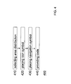
FIG. 4 illustrates a simplified flow chart diagram of
method 400 of the present invention. Method 400 to
provide code of prototype page 200 is performed by
design computer 900 and comprises the following steps:
- selecting area distribution (cf. FIGS. 5-6),
- placing icon symbols in at least one presentation
area (cf. FIG. 6),
- placing navigation symbols into the area (cf.
FIG. 6), and
- providing markup language code (cf. FIG. 7).
Details for method 400 are explained in connection with
the following figures. By selecting areas and placing
symbols, the DESIGNER assigns objects to areas
(location) and assigns objects to actions (navigation).
This assignment remains valid also for the prototype.
-
FIG. 5 illustrates area distribution. Areas y10, y20,
y30 or y40 (or "tiles", y = 5, 2, 3) divide
presentations 500, 200 or 300. For convenience, area
borders are illustrated by dashed lines. Exemplary
distribution types are type A, type B and type C
("pattern"). Letter "y" stands for 5 (presentation 50x
screen 950), for 2 (presentation 20x on screen 951) and
for 3 (presentation 30x on screen 953).
-
Areas are convenient to organize the presentation. Areas
at the top (e.g., area y10, y30) conveniently serve as
orientation guide for DESIGNER/TESTER/USER; areas at the
bottom conveniently serve to indicate a status.
-
Persons of skill in the art are able to:
- add or remove areas,
- shape the areas differently (e.g. circles,
landscapes),
- add or remove area borders,
- apply areas only to predefined screen portions.
-
FIGS. 6-12 illustrates simplified design, test and use
presentations in the example of an Internet book shop.
It is intended that computer 902 operates a bookstore
application, for example, implemented by business
software R/3 that is commercially available from SAP
Aktiengesellschaft Walldorf (Baden), Germany. The
application cooperates with a database that stores a
book catalog. Program 102 on computer 902 connects the
application and the Internet.
-
FIG. 6 illustrates an overview about consecutive design
presentations 501-504 (double-line frames) while
performing method 400. The DESIGNER operates design
computer 900 with design environment 100; in other
words, method steps 410, 420 and 430 are performed in
interaction with the DESIGNER.
-
As in presentation 501, the DESIGNER selects
distribution A (arrow standing for cursor, cf. step 410)
of screen area 510/520 by selecting graphical symbols of
predefined area distribution types A, B and C (cf.
FIG. 6).
-
As in presentation 502, selected area distribution
510/520 (type A) is presented on full screen. Presenting
areas 510/520 with borders (dashed line) is convenient.
As in presentation 503, the DESIGNER places icon symbol
521 for user activity CAT (e.g., start searching in book
catalog; cf. step 420). Also, the DESIGNER places icon
symbol 522 for user activity SEL (e.g., selecting a
book) into area 520.
-
Icon symbols 521 and 522 are related to corresponding
pictures 221 and 222 in prototype presentations 201 and
202, respectively (cf. FIG. 8) and related to objects
321 and 322 in use presentations 301 and 302,
respectively (cf. FIGS. 9-10).
-
Placing symbols 521 and 522 into common area 520 means
that the corresponding pictures 221 and 222 as well as
corresponding objects 321 and 322 appear in that common
area 220/320 (cf. FIGS. 8-10).
-
As in presentation 504, the DESIGNER places navigation
symbol 550 (cf. step 430). Convenient for symbol 550 is
an arrow with head 552 pointing to icon 522. Symbol 550
graphically links icon symbols 521 and 522 to indicate
that corresponding objects will be presented
subsequently.
-
As in presentation 504, symbol 550 has a further
function. Arrow symbol 550 has origin 551 (e.g., dot)
that the DESIGNER has placed at icon symbol 521. By
placing origin 551 over symbol 521; the DESIGNER
indicates to make the corresponding object (i.e. object
321) interactive.
-
Presentation 504 can be considered as a state diagram
(for the use presentation). Placing origin 551 in
interactive function enhances the known User Environment
Design (UED) diagram (cf. Beyer/Holtzblatt reference,
figures 14.4 and 14.5).
-
FIG. 7 illustrates an overview about code in page 200 to
provide prototype presentations 201 and 202 (cf.
FIG. 8). Preferably, code is provided in a language that
is hyper text markup language (HTML), extensible markup
language (XML), extensible hyper text markup language
(XHTML), wireless application markup language (WML), and
Standard Generalized Markup Language (SGML), Java,
JavaScript or a any combination thereof. Convenient is
initially providing code in XML and subsequently
converting the code into HTML.
-
Using predefined symbol-to-code conversion rules, the
example code converts distribution and placement
information (cf. steps 410-430) into HTML.
-
Location indicating code corresponds to the area
distribution (A), for example, by using framesets for
areas 210 and 220. The 20/80 per cent division is
exemplary and could be determined in step selecting 410.
First and second picture code is, for example, the
identification of picture files (e.g., *.jpg, *.gif)
that technically represent first icon symbol 521 ("CAT",
picture 221 "ENTER CATALOG") and second icon symbol 522
("SEL", picture 222 "TITLE SELECTION"). Picture code is
combined with location code, in the example, by
including the code into frame "220.htm".
-
Interaction code corresponds to navigation symbol 550
for presenting first picture 221 prior to second picture
222. In the example, picture 221 is the hyperlink to
picture 222.
Optionally is code for frame 210 (e.g., color coding).
-
FIG. 8 illustrates prototype presentations 201/202 by
test computer 901. Browser 101 interprets page 200
(e.g., code of FIG. 7) to consecutively display
presentations 201 and 202. Areas 210 and 220 are
conveniently distinguished by color. Picture 221 is
interactive. The TESTER operates the mouse (arrow
symbol) to navigate to picture 222.
Consecutive presentations 201/202 are the dynamic
equivalent to the - in view of navigation - static
presentation 504 (designed by the DESIGNER).
-
As mentioned, prototype page 200 is converted to use
page 300 by adding more details (e.g., title, status
bars, toolbars, buttons, fields, radio buttons,
checkboxes, drop down list boxes, tables, trees, charts
or the like).
-
FIGS. 9-12 illustrate use presentations 30x for an
extended bookstore example (screen 953, use computer
903). Advice objects 311-314 are added to area 310. In
area 320, objects 321 and 322 have been mentioned above;
objects 323AB and 324 are added.
Objects are classified into advice objects that inform
the USER (e.g., status fields) and interaction objects
by that the USER navigates and inputs data (e.g.,
buttons and input fields). This distinction is however
not essential for the present invention.
The figures show how the USER navigates during
program/use time TB /cf. FIG. 2). Presentations 301-304
are illustrated by double-line frames. Bold arrows
(right up) symbolize a pointing device (e.g. mouse
cursor).
Within first area 310, advice objects 311-314 instruct
the USER (e.g., "WELCOME ..."); within second area 320,
interaction objects 321-324 invite the USER to navigate
(e.g., "SEARCH").
-
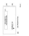
FIG. 9 illustrate the first interaction "OPEN CATALOG"
by first use presentation 301.
The USER (computer 903) has navigated to the bookstores
homepage (e.g., network address of computer 902).
Presentation 301 has advice object 311 "WELCOME..." as
headline, interaction object 321 "SEARCH" to call a
catalog function. The USER selects the catalog by
pointing to object 321.
-
FIG. 10 illustrates a second interaction by second use
presentation 302. Advice object 312 "SELECT" replaces
object 311, and interaction object 322 replaces object
321. This corresponds to the scenario described in
connection with FIGS. 6-8.
When interacting with object 322, the USER selects the
book DOG from the catalog (e.g., DOG, BIRD, FISH).
-
FIG. 11 illustrates a third interaction by third use
presentation 303. Advice object 313 "MOVE TO SHOPPING
LIST" replaces object 312, and interaction objects 323AB
replace object 322. Objects 323A is an icon of the book
DOG and object 323B is a shopping list (alternatively, a
shopping basket). When interacting, with objects 323AB,
the USER drags object 323A (book) over object 323B
(list).
-
FIG. 12 illustrates a fourth interaction by fourth use
presentation 304. Advice object 314 "ORDER DETAILS"
replaces object 313, and interaction object 324 replaces
objects 323AB. Object 324 is a table with input fields
(hatched) that invites the USER to input name, post
address, bank information and the like.
-
The following describes optional embodiments of the
invention.
Navigation symbols (in the design presentation) can have
attributes so that differently looking symbols
distinguish difference actions (in the use
presentation).
Navigation symbols can indicate default settings; for
example, dashed frames can correspond to pictures and
objects that are shown first.
Concerning the object-to-area assignment, advice objects
are optionally assigned to areas in top position (e.g.,
area 210), and interactive objects are optionally
assigned to areas where the USER operates use computer
903.
In design presentation, pictures can be simplified by
replacing pictures by text strings. For example, to
present "pictures" for advice objects 311-314 with texts
like "WELCOME ...", code in page 200 is simplified to
text strings.
Pictures files can stand for a variety of interactive
elements, tables, help function, tree symbols and the
like.
References
-
- 100
- design environment (DE)
- 101
- browser (B)
- 102
- use program (UP)
- 103
- browser (B)
- 200
- prototype page (ProtoPa)
- 20x
- presentations (P)
- 210/220
- area distribution
- 221,222
- pictures
- 300
- use page (UsePa)
- 30x
- use presentations (P)
- 311-314
- advice objects
- 321-324
- interaction objects
- 400
- method
- 410-440
- method steps
- 50x
- design presentations (P)
- 510/520
- area distribution
- 521,522
- icon symbols
- 550
- navigation symbol
- 551
- origin
- 552
- head
- 900
- design computer
- 901
- test computer
- 902
- program computer
- 903
- use computer
- 950
- screen of computer 900
- 951
- screen of computer 901
- 953
- screen of computer 903
- TA
- design/test time
- TB
- program/use time
- y10, y20
- areas in presentations