EP1356491B1 - Compliant tension mask assembly - Google Patents
Compliant tension mask assembly Download PDFInfo
- Publication number
- EP1356491B1 EP1356491B1 EP02707481A EP02707481A EP1356491B1 EP 1356491 B1 EP1356491 B1 EP 1356491B1 EP 02707481 A EP02707481 A EP 02707481A EP 02707481 A EP02707481 A EP 02707481A EP 1356491 B1 EP1356491 B1 EP 1356491B1
- Authority
- EP
- European Patent Office
- Prior art keywords
- mask
- intermediate members
- frame
- members
- tension
- Prior art date
- Legal status (The legal status is an assumption and is not a legal conclusion. Google has not performed a legal analysis and makes no representation as to the accuracy of the status listed.)
- Expired - Lifetime
Links
Images


Classifications
-
- H—ELECTRICITY
- H01—ELECTRIC ELEMENTS
- H01J—ELECTRIC DISCHARGE TUBES OR DISCHARGE LAMPS
- H01J29/00—Details of cathode-ray tubes or of electron-beam tubes of the types covered by group H01J31/00
- H01J29/02—Electrodes; Screens; Mounting, supporting, spacing or insulating thereof
- H01J29/06—Screens for shielding; Masks interposed in the electron stream
- H01J29/07—Shadow masks for colour television tubes
- H01J29/073—Mounting arrangements associated with shadow masks
-
- H—ELECTRICITY
- H01—ELECTRIC ELEMENTS
- H01J—ELECTRIC DISCHARGE TUBES OR DISCHARGE LAMPS
- H01J29/00—Details of cathode-ray tubes or of electron-beam tubes of the types covered by group H01J31/00
- H01J29/02—Electrodes; Screens; Mounting, supporting, spacing or insulating thereof
-
- H—ELECTRICITY
- H01—ELECTRIC ELEMENTS
- H01J—ELECTRIC DISCHARGE TUBES OR DISCHARGE LAMPS
- H01J2229/00—Details of cathode ray tubes or electron beam tubes
- H01J2229/07—Shadow masks
- H01J2229/0716—Mounting arrangements of aperture plate to frame or vessel
Definitions
- This invention relates to color picture tubes having tension masks, and particularly to a tension mask assembly having means for connecting a tension mask to a support frame to improve compliance.
- a color picture tube includes an electron gun for generating and directing three electron beams to the screen of the tube.
- the screen is located on the inner surface of a faceplate of the tube and is made up of an array of elements of three different color emitting phosphors.
- a color selection electrode which may be either a shadow mask or a focus mask, is interposed between the gun and the screen to permit each electron beam to strike only the phosphor elements associated with that beam.
- a shadow mask is a thin sheet of metal, such as steel, that is usually contoured to somewhat parallel the inner surface of the tube faceplate.
- One type of color picture tube has a tension mask affixed to two parallel support frame members under tension and mounted within a faceplate panel thereof.
- the tension assists in controlling vibration, or microphonics, of the mask during tube operation.
- the mask and frame are passed through a furnace and heated to very high temperatures thereby causing the frame and mask to expand. During this heating cycle, the mask and frame materials lose strength and deform beyond their plasticity limits.
- the tension on the mask is reduced by approximately the ratio of the total plastic deformation to the original compliance .
- Conventional frame designs have high center compliance but very low edge compliance. The low edge compliance provides little reserve for tension control at the edges of the mask.
- the compliance pattern of the conventional frame results in mask deformation which can wrinkle the mask.
- the mask In order to maintain the tension on the mask in a conventional tension mask frame, the mask must be attached to a relatively massive support frame. It has been suggested that a lighter frame could be used in a tension mask tube if the required tension on a mask is reduced.
- One way to reduce the required mask tension is to make the mask from a material having a low coefficient of thermal expansion.
- a mask from such material would require a support frame of a material having a similar coefficient of thermal expansion, to prevent any mismatch of expansions during thermal processing that is required for tube manufacturing. Because the metal materials that have low coefficients of thermal expansion are relatively expensive, it is relatively costly to make both the mask and frame out of identical or similar low expansion materials.
- WO-A-0060636 describes a colour picture tube having a compliant tension mask frame assembly mounted within the tube and comprising a pair of parallel intermediate member to which the mask is attached in tension.
- the present invention seeks to provide an improvement in such color picture tube having a compliant tension mask frame assembly mounted within the tube.
- the tension mask frame assembly includes a peripheral frame having opposing side support frame members and a pair of parallel intermediate members. Each intermediate member is attached to a side member at a single location between the distal ends of the intermediate members.
- the mask is held in tension by the intermediate members which provide means for higher edge compliance relative to the compliance in the center of the frame. Such a compliance pattern allows avoidance of wrinkles without losing an unacceptable amount of tension.
- the present invention may further provide means of using materials having different coefficients of thermal expansion.
- the intermediate members can be of a material similar to that of the mask having a first coefficient of thermal expansion and the peripheral frame can be constructed of a material having second coefficient of thermal expansion.
- the tension mask and intermediate members can be constructed out of Invar or similar material that has a relatively low coefficient of thermal expansion to that of the material used to form the peripheral frame.
- the peripheral frame includes clips which serve as guides to hold the intermediate members to the frame, while permitting expansion of the frame relative to the intermediate members and preventing any undesirable distortion of the intermediate members.
- FIG. 1 shows a color picture tube 10 having a glass envelope 11 comprising a rectangular faceplate panel 12 and a tubular neck 14 connected by a funnel 15.
- the funnel 15 has an internal conductive coating (not shown) that extends from an anode button 16 toward the panel 12 and to the neck 14.
- the panel 12 comprises a substantially cylindrical viewing faceplate 18 and a peripheral flange or sidewall 20, which is sealed to the funnel 15 by a glass frit 17.
- a three-color phosphor screen 22 is carried by the inner surface of the faceplate 18.
- the screen 22 is a line screen with the phosphor lines arranged in triads, each triad including a phosphor line of each of the three colors.
- a tension mask frame assembly 24 is removably mounted in predetermined spaced relation to the screen 22.
- An electron gun 26 shown schematically by dashed lines in FIG. 1 , is centrally mounted within the neck 14 to generate and direct three inline electron beams, a center beam and two side or outer beams, along convergent paths through the tension mask frame assembly 24 to the screen 22.
- the tube 10 is designed to be used with an external magnetic deflection yoke, such as the yoke 30 shown in the neighborhood of the funnel-to-neck junction.
- an external magnetic deflection yoke such as the yoke 30 shown in the neighborhood of the funnel-to-neck junction.
- the yoke 30 subjects the three beams to magnetic fields which cause the beams to scan horizontally and vertically in a rectangular raster over the screen 22.
- the tension mask frame assembly 24, as shown in FIG. 2 includes a peripheral frame 28 that includes two opposed long side support frame members 32 and 34, and two opposed short side support frame members 36 and 38.
- the two long side support frame members 32 and 34 of the frame parallel a central major axis, X, of the tube; and the two short sides 36 and 38 parallel a central minor axis, Y, of the tube.
- the tension mask frame assembly 24 further includes an apertured mask 27 and a pair opposed intermediate members 40.
- the intermediate member 40 may vary in height from the center of each section longitudinally to the ends of the sections to permit the best curvature and tension compliance over the mask.
- Each intermediate member 40 extends the length of a long side support frame member, 32 and 34.
- the intermediate members 40 are welded to the peripheral frame 28 at a single location 50 on the long sides support frame members, 32 and 34.
- the tension mask 27 is welded along the longitudinal upper distal edges of the two parallel intermediate members 40.
- the intermediate members 40 may be constructed of a material that has a coefficient of thermal expansion similar to that of the mask 27. Therefore, changes of temperature will have little effect on the position of the mask 27 relative to the intermediate members 40.
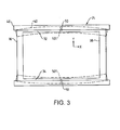
- FIG. 3 is an illustration showing, in dashed lines, the compliance of the intermediate members 40 supporting a tension mask (not shown).
- the attachment point at central location 50 is also shown (as 501) at positions where the long side support frame member 32 and 34 deform under the tension load of the mask (not shown).
- the graph shown in FIG. 4 illustrates the compliance characteristic at the distal ends 52 and 54 (as shown in FIG. 2 ) of the intermediate members 40. Attachment of the intermediate members 40 only at one point permits ends 52 and 54 to deflect free from the outer edges of the peripheral frame 28. Specifically, since the ends of the intermediate members 40 are not attached to the peripheral frame 28, the intermediate members 40 provide increased compliance at the edge of the tension mask.
- the intermediate member 40 has a generally T-shape cross section with the two distal ends, 52 and 54 held by two clips, 56 and 58, respectively, having an upwardly opening channel portion 60 and longitudinal extending slot 62.
- the intermediate member 40 includes inner guide elements 64 and 66 disposed within said channel portion 60 and slot 62.
- the T-shaped intermediate members are longitudinally spaced relative to the clips 56 and 58 so as to define internal cavities 68 and 70 within which the inner guide elements 64 and 66 of the intermediate member 40 is vertically slidably supported so as to serve as guides that hold the intermediate member 40 to prevent rotation of the member near its end, while permitting longitudinal movement of the intermediate member 40, caused by its expansion during tube operation, relative to the peripheral frame 28.
- the clips 56 and 58 either may be formed by cutouts extending from the peripheral frame 28, or may be separate parts that are secured to the frame.
- An advantage of the present invention is that the tension mask frame assembly allows for increased compliance at the edges of the mask. This increased edge compliance and improved compliance distribution allows the frame to reliably control tension and prevent wrinkles in the mask, thus improving efficiency in the manufacturing process.
- the present invention provides the means for using materials for the mask and frame with significantly different coefficients of thermal expansion.
- long side and short side support frame members have been shown as hollow square tubes, other preferred configurations, such as those having L-shaped, C-shaped or triangular-shaped cross-sections, are also possible for these sections. It is, therefore, intended that the foregoing description be regarded as illustrative rather than limiting, and that the scope of the invention is given by the appended claims.
Description
- This invention relates to color picture tubes having tension masks, and particularly to a tension mask assembly having means for connecting a tension mask to a support frame to improve compliance.
- A color picture tube includes an electron gun for generating and directing three electron beams to the screen of the tube. The screen is located on the inner surface of a faceplate of the tube and is made up of an array of elements of three different color emitting phosphors. A color selection electrode, which may be either a shadow mask or a focus mask, is interposed between the gun and the screen to permit each electron beam to strike only the phosphor elements associated with that beam. A shadow mask is a thin sheet of metal, such as steel, that is usually contoured to somewhat parallel the inner surface of the tube faceplate.
- One type of color picture tube has a tension mask affixed to two parallel support frame members under tension and mounted within a faceplate panel thereof. The tension assists in controlling vibration, or microphonics, of the mask during tube operation. During the manufacturing of the CRT, the mask and frame are passed through a furnace and heated to very high temperatures thereby causing the frame and mask to expand. During this heating cycle, the mask and frame materials lose strength and deform beyond their plasticity limits. When the mask and frame are cooled thereafter the tension on the mask is reduced by approximately the ratio of the total plastic deformation to the original compliance . Conventional frame designs have high center compliance but very low edge compliance. The low edge compliance provides little reserve for tension control at the edges of the mask. The compliance pattern of the conventional frame results in mask deformation which can wrinkle the mask. In order to maintain the tension on the mask in a conventional tension mask frame, the mask must be attached to a relatively massive support frame. It has been suggested that a lighter frame could be used in a tension mask tube if the required tension on a mask is reduced. One way to reduce the required mask tension is to make the mask from a material having a low coefficient of thermal expansion. However, a mask from such material would require a support frame of a material having a similar coefficient of thermal expansion, to prevent any mismatch of expansions during thermal processing that is required for tube manufacturing. Because the metal materials that have low coefficients of thermal expansion are relatively expensive, it is relatively costly to make both the mask and frame out of identical or similar low expansion materials. Therefore, it is desirable to use the combination of a low expansion tension mask with a higher expansion support frame, and to provide a solution to the problem that exists when there is a substantial mismatch in coefficients of thermal expansion between a tension mask and its support frame. It is also desirable to provide a means for modifying the pattern of compliance of the mask frame to control tension on the mask lost through thermal processing and to prevent wrinkling of the mask.
WO-A-0060636 - The present invention seeks to provide an improvement in such color picture tube having a compliant tension mask frame assembly mounted within the tube. The tension mask frame assembly includes a peripheral frame having opposing side support frame members and a pair of parallel intermediate members. Each intermediate member is attached to a side member at a single location between the distal ends of the intermediate members. The mask is held in tension by the intermediate members which provide means for higher edge compliance relative to the compliance in the center of the frame. Such a compliance pattern allows avoidance of wrinkles without losing an unacceptable amount of tension.
- The present invention may further provide means of using materials having different coefficients of thermal expansion. In such case, the intermediate members can be of a material similar to that of the mask having a first coefficient of thermal expansion and the peripheral frame can be constructed of a material having second coefficient of thermal expansion. For example, the tension mask and intermediate members can be constructed out of Invar or similar material that has a relatively low coefficient of thermal expansion to that of the material used to form the peripheral frame. Furthermore, the peripheral frame includes clips which serve as guides to hold the intermediate members to the frame, while permitting expansion of the frame relative to the intermediate members and preventing any undesirable distortion of the intermediate members.
- In the drawings:
-
FIGURE 1 is a side view, partly in axial section, of a color picture tube. -
FIGURE 2 is a perspective view of a tension mask-frame assembly. -
FIGURE 3 is a plan view of the mask frame assembly with the tension mask removed for clarity and illustrating the compliance of the intermediate members. -
FIGURE 4 is an explanatory diagram showing compliance distribution. -
FIGURE 5 is a plan view of a preferred embodiment of the present invention. -
FIGURE 6 shows a view of the embodiment inFIG. 5 along line 1-1. -
FIGURE 7 shows a view of the embodiment inFIG. 5 along line 2-2. -
FIG. 1 shows acolor picture tube 10 having aglass envelope 11 comprising arectangular faceplate panel 12 and atubular neck 14 connected by afunnel 15. Thefunnel 15 has an internal conductive coating (not shown) that extends from ananode button 16 toward thepanel 12 and to theneck 14. Thepanel 12 comprises a substantiallycylindrical viewing faceplate 18 and a peripheral flange orsidewall 20, which is sealed to thefunnel 15 by a glass frit 17. A three-color phosphor screen 22 is carried by the inner surface of thefaceplate 18. Thescreen 22 is a line screen with the phosphor lines arranged in triads, each triad including a phosphor line of each of the three colors. A tensionmask frame assembly 24 is removably mounted in predetermined spaced relation to thescreen 22. Anelectron gun 26, shown schematically by dashed lines inFIG. 1 , is centrally mounted within theneck 14 to generate and direct three inline electron beams, a center beam and two side or outer beams, along convergent paths through the tensionmask frame assembly 24 to thescreen 22. - The
tube 10 is designed to be used with an external magnetic deflection yoke, such as theyoke 30 shown in the neighborhood of the funnel-to-neck junction. When activated, theyoke 30 subjects the three beams to magnetic fields which cause the beams to scan horizontally and vertically in a rectangular raster over thescreen 22. - The tension
mask frame assembly 24, as shown inFIG. 2 , includes aperipheral frame 28 that includes two opposed long sidesupport frame members support frame members support frame members short sides mask frame assembly 24 further includes anapertured mask 27 and a pair opposedintermediate members 40. Theintermediate member 40 may vary in height from the center of each section longitudinally to the ends of the sections to permit the best curvature and tension compliance over the mask. - Each
intermediate member 40 extends the length of a long side support frame member, 32 and 34. Theintermediate members 40 are welded to theperipheral frame 28 at asingle location 50 on the long sides support frame members, 32 and 34. Thetension mask 27 is welded along the longitudinal upper distal edges of the two parallelintermediate members 40. Theintermediate members 40 may be constructed of a material that has a coefficient of thermal expansion similar to that of themask 27. Therefore, changes of temperature will have little effect on the position of themask 27 relative to theintermediate members 40. -
FIG. 3 is an illustration showing, in dashed lines, the compliance of theintermediate members 40 supporting a tension mask (not shown). The attachment point atcentral location 50 is also shown (as 501) at positions where the long sidesupport frame member - The graph shown in
FIG. 4 illustrates the compliance characteristic at thedistal ends 52 and 54 (as shown inFIG. 2 ) of theintermediate members 40. Attachment of theintermediate members 40 only at one point permits ends 52 and 54 to deflect free from the outer edges of theperipheral frame 28. Specifically, since the ends of theintermediate members 40 are not attached to theperipheral frame 28, theintermediate members 40 provide increased compliance at the edge of the tension mask. - According to the present invention shown in
FIGS. 5-7 , theintermediate member 40 has a generally T-shape cross section with the two distal ends, 52 and 54 held by two clips, 56 and 58, respectively, having an upwardlyopening channel portion 60 and longitudinal extendingslot 62. Theintermediate member 40 includesinner guide elements channel portion 60 andslot 62. The T-shaped intermediate members are longitudinally spaced relative to theclips internal cavities inner guide elements intermediate member 40 is vertically slidably supported so as to serve as guides that hold theintermediate member 40 to prevent rotation of the member near its end, while permitting longitudinal movement of theintermediate member 40, caused by its expansion during tube operation, relative to theperipheral frame 28. Theclips peripheral frame 28, or may be separate parts that are secured to the frame. - An advantage of the present invention is that the tension mask frame assembly allows for increased compliance at the edges of the mask. This increased edge compliance and improved compliance distribution allows the frame to reliably control tension and prevent wrinkles in the mask, thus improving efficiency in the manufacturing process. In addition, the present invention provides the means for using materials for the mask and frame with significantly different coefficients of thermal expansion.
- Many other embodiments are possible within the scope of the invention. For example, although the long side and short side support frame members have been shown as hollow square tubes, other preferred configurations, such as those having L-shaped, C-shaped or triangular-shaped cross-sections, are also possible for these sections. It is, therefore, intended that the foregoing description be regarded as illustrative rather than limiting, and that the scope of the invention is given by the appended claims.
Claims (4)
- A color picture tube (10) having a compliant tension mask frame assembly (24) mounted within said tube, a peripheral frame (28) having opposing side support frame members (32, 34, 36, 38) and a pair of parallel intermediate members (40), each of the intermediate members having two distal ends (52, 54), the distal ends being held by clips (56, 58), characterized by each of the intermediate members having a T-shaped cross section and being attached to the frame at a single location between the distal ends of each of the intermediate members, each of the clips slidably supporting the intermediate members and permitting longitudinal movement of the intermediate members; and,
a mask (27) attached to the intermediate members whereby the mask is held in tension between the intermediate members. - The color picture tube as defined in claim 1, characterized in that the peripheral frame (28) further comprises two opposed long side members (32,34) and two opposed short side support frame members (36,38) wherein the intermediate members (40) are attached to at least one of the two opposed side members.
- The color picture tube as defined in claim 1, characterized in that the mask (27) and the intermediate members (40) are made from a material having a first coefficient of thermal expansion and the peripheral frame is made from a material having a second coefficient of thermal expansion.
- The color picture tube as defined in claim 3, characterized in that the first coefficient of thermal expansion is relatively lower than the second coefficient of thermal expansion.
Applications Claiming Priority (3)
| Application Number | Priority Date | Filing Date | Title |
|---|---|---|---|
| US26276501P | 2001-01-20 | 2001-01-20 | |
| US262765P | 2001-01-20 | ||
| PCT/US2002/001053 WO2002058098A1 (en) | 2001-01-20 | 2002-01-16 | Compliant tension mask assembly |
Publications (2)
| Publication Number | Publication Date |
|---|---|
| EP1356491A1 EP1356491A1 (en) | 2003-10-29 |
| EP1356491B1 true EP1356491B1 (en) | 2008-07-02 |
Family
ID=22998938
Family Applications (1)
| Application Number | Title | Priority Date | Filing Date |
|---|---|---|---|
| EP02707481A Expired - Lifetime EP1356491B1 (en) | 2001-01-20 | 2002-01-16 | Compliant tension mask assembly |
Country Status (9)
| Country | Link |
|---|---|
| EP (1) | EP1356491B1 (en) |
| JP (1) | JP2004518255A (en) |
| KR (1) | KR20030071842A (en) |
| CN (1) | CN1267955C (en) |
| DE (1) | DE60227341D1 (en) |
| HU (1) | HUP0302315A2 (en) |
| MX (1) | MXPA03006447A (en) |
| MY (1) | MY134117A (en) |
| WO (1) | WO2002058098A1 (en) |
Families Citing this family (6)
| Publication number | Priority date | Publication date | Assignee | Title |
|---|---|---|---|---|
| US6597095B2 (en) * | 2001-11-20 | 2003-07-22 | Thomson Licensing S. A. | Cathode ray tube mask frame assembly |
| EP1480642B1 (en) | 2002-02-25 | 2008-11-26 | Eli Lilly And Company | Peroxisome proliferator activated receptor modulators |
| US6812628B2 (en) | 2002-05-09 | 2004-11-02 | Thomson Licensing S.A. | Bracket for mounting a shadow mask frame |
| WO2006073392A1 (en) * | 2005-01-04 | 2006-07-13 | Thomson Licensing S. A. | Cathode ray tube having a tension mask and support frame assembly with dissimilar thermal expansion materials |
| KR200449554Y1 (en) * | 2008-02-19 | 2010-07-20 | 김경남 | a gas burner |
| KR101865757B1 (en) | 2017-12-06 | 2018-06-08 | 김기성 | Water treatment device for low impact development |
Family Cites Families (3)
| Publication number | Priority date | Publication date | Assignee | Title |
|---|---|---|---|---|
| JP3088616B2 (en) * | 1994-08-11 | 2000-09-18 | 松下電器産業株式会社 | Method for manufacturing color selection electrode for color picture tube |
| JP3175722B2 (en) * | 1999-02-10 | 2001-06-11 | 関西日本電気株式会社 | Color cathode ray tube |
| US6246164B1 (en) * | 1999-04-01 | 2001-06-12 | Thomson Licensing S.A. | Color picture tube having a low expansion tension mask attached to a higher expansion frame |
-
2002
- 2002-01-16 HU HU0302315A patent/HUP0302315A2/en unknown
- 2002-01-16 EP EP02707481A patent/EP1356491B1/en not_active Expired - Lifetime
- 2002-01-16 CN CNB028039246A patent/CN1267955C/en not_active Expired - Fee Related
- 2002-01-16 JP JP2002558296A patent/JP2004518255A/en active Pending
- 2002-01-16 KR KR10-2003-7009638A patent/KR20030071842A/en not_active Application Discontinuation
- 2002-01-16 MX MXPA03006447A patent/MXPA03006447A/en active IP Right Grant
- 2002-01-16 WO PCT/US2002/001053 patent/WO2002058098A1/en active Application Filing
- 2002-01-16 DE DE60227341T patent/DE60227341D1/en not_active Expired - Fee Related
- 2002-01-21 MY MYPI20020223A patent/MY134117A/en unknown
Also Published As
| Publication number | Publication date |
|---|---|
| WO2002058098A1 (en) | 2002-07-25 |
| MY134117A (en) | 2007-11-30 |
| KR20030071842A (en) | 2003-09-06 |
| CN1488158A (en) | 2004-04-07 |
| DE60227341D1 (en) | 2008-08-14 |
| MXPA03006447A (en) | 2003-09-22 |
| HUP0302315A2 (en) | 2007-01-29 |
| JP2004518255A (en) | 2004-06-17 |
| CN1267955C (en) | 2006-08-02 |
| EP1356491A1 (en) | 2003-10-29 |
Similar Documents
| Publication | Publication Date | Title |
|---|---|---|
| US4056755A (en) | Color picture tube having mask-frame assembly with reduced thickness | |
| CA1283440C (en) | Cathode-ray tube having shadow mask for low overscan | |
| US6246164B1 (en) | Color picture tube having a low expansion tension mask attached to a higher expansion frame | |
| EP1356491B1 (en) | Compliant tension mask assembly | |
| US6084342A (en) | Color picture tube having a tensioned mask-support frame assembly | |
| US6455992B1 (en) | Color picture tube having a low expansion tension mask attached to a higher expansion frame | |
| US6407488B1 (en) | Color picture tube having a low expansion tension mask | |
| US6930445B2 (en) | Compliant tension mask assembly | |
| US6731055B2 (en) | Color picture tube having a low expansion tension mask attached to a higher expansion frame | |
| EP1428239B1 (en) | Color picture tube having a low expansion tension mask attached to a higher expansion frame | |
| US6590326B2 (en) | Apparatus for maintaining tension in a shadow mask | |
| US6600258B2 (en) | Tension mask for a cathode-ray-tube | |
| US6274975B1 (en) | Color picture tube having a tension mask attached to a frame | |
| JP3471493B2 (en) | Color cathode ray tube | |
| KR100349194B1 (en) | Shadow mask of color cathode ray tube | |
| KR20000041354A (en) | Method for fabricating shadow mask for color braun tube |
Legal Events
| Date | Code | Title | Description |
|---|---|---|---|
| PUAI | Public reference made under article 153(3) epc to a published international application that has entered the european phase |
Free format text: ORIGINAL CODE: 0009012 |
|
| 17P | Request for examination filed |
Effective date: 20030716 |
|
| AK | Designated contracting states |
Kind code of ref document: A1 Designated state(s): AT BE CH CY DE DK ES FI FR GB GR IE IT LI LU MC NL PT SE TR |
|
| AX | Request for extension of the european patent |
Extension state: AL LT LV MK RO SI |
|
| RAP1 | Party data changed (applicant data changed or rights of an application transferred) |
Owner name: THOMSON LICENSING S.A. |
|
| 17Q | First examination report despatched |
Effective date: 20050107 |
|
| RAP1 | Party data changed (applicant data changed or rights of an application transferred) |
Owner name: THOMSON LICENSING |
|
| GRAP | Despatch of communication of intention to grant a patent |
Free format text: ORIGINAL CODE: EPIDOSNIGR1 |
|
| GRAS | Grant fee paid |
Free format text: ORIGINAL CODE: EPIDOSNIGR3 |
|
| GRAA | (expected) grant |
Free format text: ORIGINAL CODE: 0009210 |
|
| AK | Designated contracting states |
Kind code of ref document: B1 Designated state(s): DE FR GB |
|
| REG | Reference to a national code |
Ref country code: GB Ref legal event code: FG4D |
|
| REF | Corresponds to: |
Ref document number: 60227341 Country of ref document: DE Date of ref document: 20080814 Kind code of ref document: P |
|
| PLBE | No opposition filed within time limit |
Free format text: ORIGINAL CODE: 0009261 |
|
| STAA | Information on the status of an ep patent application or granted ep patent |
Free format text: STATUS: NO OPPOSITION FILED WITHIN TIME LIMIT |
|
| PGFP | Annual fee paid to national office [announced via postgrant information from national office to epo] |
Ref country code: DE Payment date: 20090120 Year of fee payment: 8 |
|
| 26N | No opposition filed |
Effective date: 20090403 |
|
| PGFP | Annual fee paid to national office [announced via postgrant information from national office to epo] |
Ref country code: GB Payment date: 20081230 Year of fee payment: 8 |
|
| PGFP | Annual fee paid to national office [announced via postgrant information from national office to epo] |
Ref country code: FR Payment date: 20090123 Year of fee payment: 8 |
|
| GBPC | Gb: european patent ceased through non-payment of renewal fee |
Effective date: 20100116 |
|
| REG | Reference to a national code |
Ref country code: FR Ref legal event code: ST Effective date: 20100930 |
|
| PG25 | Lapsed in a contracting state [announced via postgrant information from national office to epo] |
Ref country code: FR Free format text: LAPSE BECAUSE OF NON-PAYMENT OF DUE FEES Effective date: 20100201 |
|
| PG25 | Lapsed in a contracting state [announced via postgrant information from national office to epo] |
Ref country code: DE Free format text: LAPSE BECAUSE OF NON-PAYMENT OF DUE FEES Effective date: 20100803 |
|
| PG25 | Lapsed in a contracting state [announced via postgrant information from national office to epo] |
Ref country code: GB Free format text: LAPSE BECAUSE OF NON-PAYMENT OF DUE FEES Effective date: 20100116 |