EP1347280A1 - Optical parameter measuring system with associated temperature data - Google Patents
Optical parameter measuring system with associated temperature data Download PDFInfo
- Publication number
- EP1347280A1 EP1347280A1 EP02025300A EP02025300A EP1347280A1 EP 1347280 A1 EP1347280 A1 EP 1347280A1 EP 02025300 A EP02025300 A EP 02025300A EP 02025300 A EP02025300 A EP 02025300A EP 1347280 A1 EP1347280 A1 EP 1347280A1
- Authority
- EP
- European Patent Office
- Prior art keywords
- dut
- temperature
- measurement
- measured
- measuring
- Prior art date
- Legal status (The legal status is an assumption and is not a legal conclusion. Google has not performed a legal analysis and makes no representation as to the accuracy of the status listed.)
- Pending
Links
- 230000003287 optical effect Effects 0.000 title claims abstract description 37
- 238000005259 measurement Methods 0.000 claims abstract description 48
- 238000000034 method Methods 0.000 claims abstract description 7
- 238000012360 testing method Methods 0.000 claims abstract description 4
- AHCYMLUZIRLXAA-SHYZEUOFSA-N Deoxyuridine 5'-triphosphate Chemical compound O1[C@H](COP(O)(=O)OP(O)(=O)OP(O)(O)=O)[C@@H](O)C[C@@H]1N1C(=O)NC(=O)C=C1 AHCYMLUZIRLXAA-SHYZEUOFSA-N 0.000 claims abstract 14
- 238000001816 cooling Methods 0.000 claims description 23
- 238000010438 heat treatment Methods 0.000 claims description 23
- 238000013461 design Methods 0.000 claims description 3
- 230000001360 synchronised effect Effects 0.000 claims description 3
- 239000011810 insulating material Substances 0.000 claims description 2
- 238000009529 body temperature measurement Methods 0.000 claims 1
- 230000008878 coupling Effects 0.000 claims 1
- 238000010168 coupling process Methods 0.000 claims 1
- 238000005859 coupling reaction Methods 0.000 claims 1
- 238000011156 evaluation Methods 0.000 description 4
- 239000011159 matrix material Substances 0.000 description 3
- 239000004020 conductor Substances 0.000 description 2
- 238000011161 development Methods 0.000 description 2
- 230000007613 environmental effect Effects 0.000 description 2
- 230000005540 biological transmission Effects 0.000 description 1
- 230000001419 dependent effect Effects 0.000 description 1
- 238000002955 isolation Methods 0.000 description 1
- 239000013307 optical fiber Substances 0.000 description 1
- 230000010287 polarization Effects 0.000 description 1
- 230000003595 spectral effect Effects 0.000 description 1
Images
Classifications
-
- G—PHYSICS
- G01—MEASURING; TESTING
- G01M—TESTING STATIC OR DYNAMIC BALANCE OF MACHINES OR STRUCTURES; TESTING OF STRUCTURES OR APPARATUS, NOT OTHERWISE PROVIDED FOR
- G01M99/00—Subject matter not provided for in other groups of this subclass
- G01M99/002—Thermal testing
-
- G—PHYSICS
- G01—MEASURING; TESTING
- G01M—TESTING STATIC OR DYNAMIC BALANCE OF MACHINES OR STRUCTURES; TESTING OF STRUCTURES OR APPARATUS, NOT OTHERWISE PROVIDED FOR
- G01M11/00—Testing of optical apparatus; Testing structures by optical methods not otherwise provided for
- G01M11/30—Testing of optical devices, constituted by fibre optics or optical waveguides
Definitions
- the present invention refers to measuring of optical parameters of optical devices.
- Providing a temperature signal and associating said temperature to the measured optical parameters allows a temperature depending evaluation of the optical parameters.
- An evaluation taking into consideration the temperature of the respective DUT improves the performance, the reproducibility and the reliability of the measurement.
- the measuring instrument is adapted to perform a real-time measurement of the parameters and the temperature, there can be created a very close relationship and in particular a definite association between the values of the parameters and the temperatures. This conjunction between parameters and associated temperature also allows an evaluation of the dependency of the parameters on the temperature.
- optical filters depend on temperature. For example a center wavelength of a specific type of filter, e.g. an arrayed waveguide, can be adjusted by varying temperature. With help of the invention it is possible to automatically determine the optimal operation temperature of the respective filter and to automatically characterize the filter (by measuring its parameters) at its optimal operation temperature.
- optical characteristics of optical devices generally depend on temperature.
- draught e.g. caused by opening a door of a room in which the measurement takes place, may lead to a noticeable change of temperature and therefore to falsification of the measurement.
- the measurement results are comparable and reproducible.
- the measuring system comprises a heating and/or cooling device and/or at least one interface for connecting such a heating and/or cooling device to the measuring system.
- This heating and/or cooling device is provided for an active control of the temperature of the DUT to be measured.
- the measurement instrument is directly or via the interface connected to the heating and/or cooling device and is adapted for controlling it such that the heating and/or cooling device prior to the measurement adjusts a predetermined temperature at the DUT and during the measurement observes the predetermined temperature at the DUT.
- a heating and/or cooling device it is possible to perform the measurement within a predetermined range of admissible temperatures or nearly exactly at a predetermined optimum temperature. Keeping the temperature at a predetermined level improves the performance of the measurement.
- a measuring system 1 comprises a component holder 2 adapted for providing a support of an optical device 3 to be measured.
- said device 3 is referred to as “device under test” or “DUT”; consequently the component holder 2 is also referred to as DUT holder 2.
- the DUT holder 2 can have any convenient form allowing a secure support of the DUT 3.
- the DUT holder 2 is formed as a plate or table such that the DUT 3 can be applied onto the DUT holder 2.
- the DUT holder 2 is attached to a housing 4 of the measurement system 1 in such a way, that vibrations are damped. Therefore, the DUT holder 2 and the supported DUT 3 are isolated from vibrations appearing in the environment of the housing 4 and may be transferred to the housing 4.
- the measuring system 1 also comprises at least one measuring instrument 5 with convenient hardware and software not shown.
- the measuring instrument 5 is adapted to perform measurement of optical parameters P 1, P 2 ... P n (in the following abbreviated with P) of the DUT 3.
- P optical parameters
- the measurement instrument 5 has at least one optical output 6 and at least one optical input 7.
- the output 6 of the measuring instrument 5 is connected to an optical input 8 of the DUT 3
- the input 7 of the measuring instrument 5 is connected to an optical output 9 of the DUT 3.
- optical parameters P can be e.g. spectral loss, polarization depending loss, group delay, differential group delay in transmission and/or reflection.
- An optical DUT 3 may be e.g. a simple optical fiber or an optical circuit or a highly integrated optical module.
- the measuring system 1 comprises at least one temperature sensor 10 provided for measuring a temperature T of the DUT 3.
- the measuring system 1 comprises at least one interface 11 for connecting such a temperature sensor 10.
- Fig. 1 are exemplarily shown four of such temperature sensors 10, designated with 10', 10", 10"' and 10"", respectively.
- the temperature sensors 10 are connected to the measuring instrument 5 via conductors 13 or 13', 13", 13"', 13"", respectively. These four or more or less temperature sensors 10 may be arranged alternatively or cumulatively.
- One of the temperature sensors 10 designated with 10' is arranged at a carrier 12 supported by the housing 4. This temperature sensor 10' is adapted for a non-contact and therefore remote measurement of the temperature T of the DUT 3. Another temperature sensor 10 designated with 10" is attached to the DUT 3 provided for a direct measurement of the temperature T of the DUT 3. A further temperature sensor 10 designated with 10"' is integrated into the DUT 3 adapted for measurement of an internal temperature T of the DUT 3. At last, another temperature sensor 10 designated with 10"" is integrated into the DUT holder 2 and may stay in contact with the DUT 3 providing a direct measurement of the DUT's temperature T. Other convenient arrangements of temperature sensors 10 are not excluded.
- the depicted and preferred embodiment of the measuring system 1 also comprises a heating and/or cooling device 14.
- the measuring system 1 or the measuring instrument 5, respectively comprises an interface 15 for connecting such a heating and/or cooling device 14 to the measuring system 1 or to the measuring instrument 5, respectively.
- the heating and/or cooling device 14 may have any suitable design and form.
- Fig. 1 exemplarily depicts two alternative embodiments of such heating and/or cooling device 14, designated with 14' or 14", respectively.
- the one heating and/or cooling devices 14' has the form of a plate and is supported by the carrier 12.
- the other heating and/or cooling device 14" is integrated into the DUT holder 2.
- Such a heating and/or cooling device 14 is provided to increase or decrease the temperature T of the DUT 3.
- the measuring instrument 5 is directly or via the interface 15 connected to the respective heating and/or cooling device 14 by means of a controlling conductor 16 (or 16 or 16", respectively), and is adapted for an active control of the temperature T of the DUT 3.
- the measuring instrument 5 triggers the respective heating and/or cooling device 14 for adjusting a predetermined temperature T at the DUT 3. During the measurement the measuring instrument 5 triggers the respective heating and/or cooling device 14 for observing the predetermined temperature T or for adjusting a predetermined development of the temperature T.
- the measuring system 1 as shown in Fig. 1 is also provided with a removable hood 17, which may be pivotable attached to the carrier 12, and which covers in this example the DUT holder 2, the DUT 3, the measuring instrument 5, the temperature sensor(s) 10, the carrier 12 and the heating and/or cooling device 14.
- This hood 17 protects the covered elements against environmental influences and thus improves the performance of the measurement.
- the hood 17 is made of a thermal insulating material and/or has a thermal insulating design. This configuration provides a thermal isolation of the DUT 3 from the environmental conditions, and therefore leads to further improvement of the measurement.
- the temperature sensor 10 or each of the temperature sensors 10, respectively, is adapted for providing a temperature signal correlating with the temperature T of the DUT 3, and sending it via the respective connector 13 to the measuring instrument 5.
- the measuring instrument 5 is adapted to perform a simultaneous and real-time measurement of the temperature T and the optical parameters P of the DUT 3.
- the measuring instrument 5 performs a temporally synchronized measurement simplifying an unambiguous or definite association between the optical parameters P and the temperature T of the DUT 3.
- the measuring instrument 5 may be adapted for associating a measured temperature T to each measured parameter P or to each group of measured parameters P 1, P 2. ..P n.
- the measuring instrument 5 is preferably adapted to generate a measuring protocol 18, in particular in form of a matrix.
- N is the number of each measuring interval or measuring step, in which the parameters P and the temperature T are determined.
- the measuring number N counts from 1 to X intervals or steps.
- the protocol 18 lists also C, which is a timer signal or measuring time assigned to the measuring number N and hence assigned to the parameters P and the temperature T.
- the measuring number N and the timer signal C may be provided alternatively or additionally.
- the single parameters P 1, P 2 ... P n of each measuring number N are measured simultaneously, thus belong essentially to the same measuring time C and create a group of parameters P belonging together.
- the measuring instrument 5 determines a value of the temperature T for each measuring number N and/or at each measuring time C.
- This measurement routine or process leads to an unambiguous association of a definite temperature T to each single parameter P or to each group or parameters P 1, P 2 ... P n .
- This protocol 18 allows a temperature depending evaluation of any single parameter P or of any group of parameters P 1, P 2 . . . P n. With help of the protocol 18 it is also possible to evaluate the dependency of any single parameter P and/or of any group of parameters P 1, P 2 . . . P n on the development of the temperature T. Therefore, on the one hand the performance of the parameter measurement can be improved with respect of its reliability and reproducibility. On the other hand an improved measurement leads to an improved control of quality of the optical DUTs 3.
Landscapes
- Physics & Mathematics (AREA)
- General Physics & Mathematics (AREA)
- Optics & Photonics (AREA)
- Chemical & Material Sciences (AREA)
- Analytical Chemistry (AREA)
- Testing Of Individual Semiconductor Devices (AREA)
Abstract
Description
- The present invention refers to measuring of optical parameters of optical devices.
- It is an object of the present invention to provide an improved measurement. The object is solved by the independent claim. Preferred embodiments are shown by the dependent claims.
- Providing a temperature signal and associating said temperature to the measured optical parameters allows a temperature depending evaluation of the optical parameters. An evaluation taking into consideration the temperature of the respective DUT improves the performance, the reproducibility and the reliability of the measurement.
- In the context of the present invention only optical parameters shall be referred to as "parameter", with temperature being explicitly excluded.
- Since the measuring instrument is adapted to perform a real-time measurement of the parameters and the temperature, there can be created a very close relationship and in particular a definite association between the values of the parameters and the temperatures. This conjunction between parameters and associated temperature also allows an evaluation of the dependency of the parameters on the temperature.
- Some characteristics of optical filters depend on temperature. For example a center wavelength of a specific type of filter, e.g. an arrayed waveguide, can be adjusted by varying temperature. With help of the invention it is possible to automatically determine the optimal operation temperature of the respective filter and to automatically characterize the filter (by measuring its parameters) at its optimal operation temperature.
- As mentioned above the optical characteristics of optical devices generally depend on temperature. Thus draught, e.g. caused by opening a door of a room in which the measurement takes place, may lead to a noticeable change of temperature and therefore to falsification of the measurement. With help of the invention the measurement results are comparable and reproducible.
- According to a preferred embodiment the measuring system comprises a heating and/or cooling device and/or at least one interface for connecting such a heating and/or cooling device to the measuring system. This heating and/or cooling device is provided for an active control of the temperature of the DUT to be measured. The measurement instrument is directly or via the interface connected to the heating and/or cooling device and is adapted for controlling it such that the heating and/or cooling device prior to the measurement adjusts a predetermined temperature at the DUT and during the measurement observes the predetermined temperature at the DUT. With help of such a heating and/or cooling device it is possible to perform the measurement within a predetermined range of admissible temperatures or nearly exactly at a predetermined optimum temperature. Keeping the temperature at a predetermined level improves the performance of the measurement.
- Other objects and many of the attendant advantages of the present invention will be readily appreciated and become better understood by reference to the following detailed description when considered in connection with the accompanying drawings. Features that are substantially or functionally equal or similar will be referred to with the same reference sign(s).
- Fig. 1
- is a schematic depiction of a measuring system according to the invention.
- Fig. 2
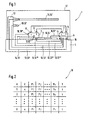
- is a schematic illustration of a measurement protocol generated by the measuring system.
- Referring to Fig. 1, a
measuring system 1 according to the invention comprises acomponent holder 2 adapted for providing a support of anoptical device 3 to be measured. In the following saiddevice 3 is referred to as "device under test" or "DUT"; consequently thecomponent holder 2 is also referred to asDUT holder 2. Basically theDUT holder 2 can have any convenient form allowing a secure support of theDUT 3. In the depicted embodiment theDUT holder 2 is formed as a plate or table such that theDUT 3 can be applied onto theDUT holder 2. Preferably theDUT holder 2 is attached to a housing 4 of themeasurement system 1 in such a way, that vibrations are damped. Therefore, theDUT holder 2 and the supportedDUT 3 are isolated from vibrations appearing in the environment of the housing 4 and may be transferred to the housing 4. - The
measuring system 1 also comprises at least one measuringinstrument 5 with convenient hardware and software not shown. Themeasuring instrument 5 is adapted to perform measurement of optical parameters P1, P2 ... Pn (in the following abbreviated with P) of theDUT 3. To this aim themeasurement instrument 5 has at least oneoptical output 6 and at least oneoptical input 7. In order to optically connect theDUT 3 to themeasuring instrument 5 theoutput 6 of themeasuring instrument 5 is connected to anoptical input 8 of theDUT 3, and theinput 7 of themeasuring instrument 5 is connected to anoptical output 9 of theDUT 3. - Such optical parameters P can be e.g. spectral loss, polarization depending loss, group delay, differential group delay in transmission and/or reflection. An
optical DUT 3 may be e.g. a simple optical fiber or an optical circuit or a highly integrated optical module. - According to the invention the
measuring system 1 comprises at least one temperature sensor 10 provided for measuring a temperature T of theDUT 3. Alternatively or additionally themeasuring system 1 comprises at least one interface 11 for connecting such a temperature sensor 10. In Fig. 1 are exemplarily shown four of such temperature sensors 10, designated with 10', 10", 10"' and 10"", respectively. The temperature sensors 10 are connected to themeasuring instrument 5 via conductors 13 or 13', 13", 13"', 13"", respectively. These four or more or less temperature sensors 10 may be arranged alternatively or cumulatively. - One of the temperature sensors 10 designated with 10' is arranged at a
carrier 12 supported by the housing 4. This temperature sensor 10' is adapted for a non-contact and therefore remote measurement of the temperature T of theDUT 3. Another temperature sensor 10 designated with 10" is attached to theDUT 3 provided for a direct measurement of the temperature T of theDUT 3. A further temperature sensor 10 designated with 10"' is integrated into theDUT 3 adapted for measurement of an internal temperature T of theDUT 3. At last, another temperature sensor 10 designated with 10"" is integrated into theDUT holder 2 and may stay in contact with theDUT 3 providing a direct measurement of the DUT's temperature T. Other convenient arrangements of temperature sensors 10 are not excluded. - The depicted and preferred embodiment of the
measuring system 1 also comprises a heating and/or cooling device 14. Alternatively or additionally themeasuring system 1 or themeasuring instrument 5, respectively, comprises aninterface 15 for connecting such a heating and/or cooling device 14 to themeasuring system 1 or to themeasuring instrument 5, respectively. The heating and/or cooling device 14 may have any suitable design and form. - Fig. 1 exemplarily depicts two alternative embodiments of such heating and/or cooling device 14, designated with 14' or 14", respectively. The one heating and/or cooling devices 14' has the form of a plate and is supported by the
carrier 12. The other heating and/or cooling device 14" is integrated into theDUT holder 2. Such a heating and/or cooling device 14 is provided to increase or decrease the temperature T of theDUT 3. Themeasuring instrument 5 is directly or via theinterface 15 connected to the respective heating and/or cooling device 14 by means of a controlling conductor 16 (or 16 or 16", respectively), and is adapted for an active control of the temperature T of theDUT 3. Therefore, prior to a measurement of parameters P themeasuring instrument 5 triggers the respective heating and/or cooling device 14 for adjusting a predetermined temperature T at theDUT 3. During the measurement themeasuring instrument 5 triggers the respective heating and/or cooling device 14 for observing the predetermined temperature T or for adjusting a predetermined development of the temperature T. - The
measuring system 1 as shown in Fig. 1 is also provided with aremovable hood 17, which may be pivotable attached to thecarrier 12, and which covers in this example theDUT holder 2, theDUT 3, themeasuring instrument 5, the temperature sensor(s) 10, thecarrier 12 and the heating and/or cooling device 14. Thishood 17 protects the covered elements against environmental influences and thus improves the performance of the measurement. In a preferred embodiment thehood 17 is made of a thermal insulating material and/or has a thermal insulating design. This configuration provides a thermal isolation of theDUT 3 from the environmental conditions, and therefore leads to further improvement of the measurement. - The temperature sensor 10 or each of the temperature sensors 10, respectively, is adapted for providing a temperature signal correlating with the temperature T of the
DUT 3, and sending it via the respective connector 13 to the measuringinstrument 5. According to the invention the measuringinstrument 5 is adapted to perform a simultaneous and real-time measurement of the temperature T and the optical parameters P of theDUT 3. Preferably the measuringinstrument 5 performs a temporally synchronized measurement simplifying an unambiguous or definite association between the optical parameters P and the temperature T of theDUT 3. In order to achieve a definite conjunction between temperature T and parameters P the measuringinstrument 5 may be adapted for associating a measured temperature T to each measured parameter P or to each group of measured parameters P1, P2. ..Pn. - Now referring to Fig. 2 the measuring
instrument 5 is preferably adapted to generate a measuringprotocol 18, in particular in form of a matrix. In theprotocol 18 or in the matrix, respectively, N is the number of each measuring interval or measuring step, in which the parameters P and the temperature T are determined. In this example the measuring number N counts from 1 to X intervals or steps. Theprotocol 18 lists also C, which is a timer signal or measuring time assigned to the measuring number N and hence assigned to the parameters P and the temperature T. The measuring number N and the timer signal C may be provided alternatively or additionally. The single parameters P1, P2 ... Pn of each measuring number N are measured simultaneously, thus belong essentially to the same measuring time C and create a group of parameters P belonging together. - As can be seen in the matrix or
protocol 18 of Fig. 2 the measuringinstrument 5 determines a value of the temperature T for each measuring number N and/or at each measuring time C. This measurement routine or process leads to an unambiguous association of a definite temperature T to each single parameter P or to each group or parameters P1, P2 ... Pn. - This
protocol 18 allows a temperature depending evaluation of any single parameter P or of any group of parameters P1, P2 . . . Pn. With help of theprotocol 18 it is also possible to evaluate the dependency of any single parameter P and/or of any group of parameters P1, P2 . . . Pn on the development of the temperature T. Therefore, on the one hand the performance of the parameter measurement can be improved with respect of its reliability and reproducibility. On the other hand an improved measurement leads to an improved control of quality of theoptical DUTs 3.
Claims (12)
- A measuring system (1) adapted for providing a measurement of an optical parameter (P) of an optical device under test - DUT - (3), comprising:wherein the measuring system (1) is adapted to receive a temperature signal comprising a plurality of values of the measured temperature (T) of the DUT (3) over the time, and to provide an output signal wherein values of the measured temperature (T) are associated to such values of the measured optical parameter (P) of the DUT (3) that correspond in time.a measuring instrument (5) adapted to perform the measurement and to provide a measurement signal comprising a plurality of values of the measured optical parameter (P) of the DUT (3) over the time,
- The measuring system (1) according to claim 1, further comprising at least one of: a temperature sensor (10), and at least one interface (11) adapted for coupling such a temperature sensor (10) to the measuring system (1), wherein the temperature sensor (10) is provided for measuring the temperature (T) of the DUT (3).
- The measuring system (1) according to claim 2, wherein the temperature sensor (T) is coupled directly or via the interface (11) to the measuring instrument (5) and is adapted for providing the measuring instrument (5) with a temperature signal correlating with the temperature (T) of the DUT (3).
- The measuring system according to claim 1 or any one of the above claims, wherein the measuring instrument (5) is adapted for providing at least one of the following features:providing a simultaneous real-time measurement of the optical parameter (P) and the temperature (T) of the DUT (3);providing a temporally synchronized real-time measurement of the optical parameter (P) and the temperature (T) of the DUT (3);providing a definite association between the measured temperatures (T) and the measured parameters (P);associating each measured parameter (P) or each group of simultaneously measured parameters (P) to a definite measured temperature (T);generating a measurement protocol (18) listing values for the DUT's temperature (T) associated to the measured parameters (P) and at least one of the group comprising: the measured parameters (P), a measuring time (C) associated to the measured parameters (P), and a measuring number (N) associated to the measured parameters (P).
- The measuring system (1) according to claim 1 or any one of the above claims, whereinthe measuring system (1) comprises a heating and/or cooling device (14) and/or at least one interface (15) for connecting such a heating and/or cooling device (14) to the measuring system (1),the heating and/or cooling device (14) is provided for an active control of the temperature (T) of the DUT (3),the measurement instrument (5) is coupled directly or via the interface (15) to the heating and/or cooling device (14) and is adapted for controlling the heating and/or cooling device (14) such that the heating and/or cooling device (14) prior to the measurement adjusts a predetermined temperature (T) at the DUT (3) and during the measurement observes the predetermined temperature (T) at the DUT (3).
- The measuring system (1) according to claim 1 or any one of the above claims, whereinthe measuring system (1) comprises a DUT holder (2) providing a support for the DUT (3),the measuring system (1) comprises a hood (17) provided for covering the DUT holder (2) including the supported DUT (3),the hood (17) has a thermal insulating design and/or is made of a thermal insulating material.
- The measuring system (1) according to claim 2 or any one of the above claims, comprising at least one of the following features:the temperature sensor (10) is attached to or integrated in the DUT (3);the temperature sensor (10) is arranged at or integrated in the DUT holder (2);the temperature sensor (10) is adapted for a remote and non-contact temperature measurement.
- A method for providing a measurement of an optical parameter (P) of an optical device under test - DUT - (3), comprising the steps of:providing a measurement signal, said measurement signal comprising a plurality of values of the measured optical parameter (P) of the DUT (3) over the time,providing a temperature signal, said temperature signal comprising a plurality of values of the measured temperature (T) of the DUT (3) over the time,deriving an output signal, wherein values of the measured temperature (T) are associated to such values of the measured optical parameter (P)of the DUT (3) that correspond in time.
- The method according to claim 8, wherein the step of measuring of the optical parameter (P) and the temperature (T) of the DUT (3) is performed as at least one of: a simultaneous real-time measurement, and a temporally synchronized real-time measurement.
- The method according to claim 8 or any one of the above claims, wherein the output signal provides a definite association between the measured temperatures (T) and the measured parameters (P).
- The method according to claim 8 or any one of the above claims, wherein each measured parameter (P) or each group of simultaneously measured parameters (P) is associated to a definite measured temperature (T).
- The method according to claim 8 or any one of the above claims, further comprising a step of generating a measurement protocol (18), said measurement protocol (18) listing values for the DUT's temperature (T) associated to the measured parameters (P) and at least one of the group comprising: the measured parameters (P), a measuring time (C) associated to the measured parameters (P), and a measuring number (N) associated to the measured parameters (P).
Priority Applications (2)
| Application Number | Priority Date | Filing Date | Title |
|---|---|---|---|
| EP02025300A EP1347280A1 (en) | 2002-11-13 | 2002-11-13 | Optical parameter measuring system with associated temperature data |
| US10/643,510 US6797927B2 (en) | 2002-11-13 | 2003-08-19 | Optical parameter measuring with temperature assignment |
Applications Claiming Priority (1)
| Application Number | Priority Date | Filing Date | Title |
|---|---|---|---|
| EP02025300A EP1347280A1 (en) | 2002-11-13 | 2002-11-13 | Optical parameter measuring system with associated temperature data |
Publications (1)
| Publication Number | Publication Date |
|---|---|
| EP1347280A1 true EP1347280A1 (en) | 2003-09-24 |
Family
ID=27771881
Family Applications (1)
| Application Number | Title | Priority Date | Filing Date |
|---|---|---|---|
| EP02025300A Pending EP1347280A1 (en) | 2002-11-13 | 2002-11-13 | Optical parameter measuring system with associated temperature data |
Country Status (2)
| Country | Link |
|---|---|
| US (1) | US6797927B2 (en) |
| EP (1) | EP1347280A1 (en) |
Cited By (1)
| Publication number | Priority date | Publication date | Assignee | Title |
|---|---|---|---|---|
| EP1710552A1 (en) * | 2004-01-27 | 2006-10-11 | Fujikura Ltd. | Multi-mode optical fiber measurement method |
Families Citing this family (2)
| Publication number | Priority date | Publication date | Assignee | Title |
|---|---|---|---|---|
| EP1191322B1 (en) * | 2001-07-13 | 2005-06-01 | Agilent Technologies, Inc. (a Delaware corporation) | Testing arrangement for optical devices |
| US7112208B2 (en) * | 2001-08-06 | 2006-09-26 | Morris John K | Compact suture punch with malleable needle |
Citations (3)
| Publication number | Priority date | Publication date | Assignee | Title |
|---|---|---|---|---|
| GB2122337A (en) * | 1982-05-18 | 1984-01-11 | Nat Res Dev | Fibre optic sensing device |
| US5741070A (en) * | 1993-11-30 | 1998-04-21 | Texas Instruments Incorporated | Apparatus for real-time semiconductor wafer temperature measurement based on a surface roughness characteristic of the wafer |
| WO2001036916A2 (en) * | 1999-11-18 | 2001-05-25 | Sensarray Corporation | Optical techniques for measuring parameters such as temperature |
Family Cites Families (3)
| Publication number | Priority date | Publication date | Assignee | Title |
|---|---|---|---|---|
| US5838437A (en) * | 1997-04-09 | 1998-11-17 | Micron Optics, Inc. | Reference system for optical devices including optical scanners and spectrum analyzers |
| WO2000016453A1 (en) * | 1998-09-11 | 2000-03-23 | New Focus, Inc. | Tunable laser |
| US6621275B2 (en) * | 2001-11-28 | 2003-09-16 | Optonics Inc. | Time resolved non-invasive diagnostics system |
-
2002
- 2002-11-13 EP EP02025300A patent/EP1347280A1/en active Pending
-
2003
- 2003-08-19 US US10/643,510 patent/US6797927B2/en not_active Expired - Fee Related
Patent Citations (3)
| Publication number | Priority date | Publication date | Assignee | Title |
|---|---|---|---|---|
| GB2122337A (en) * | 1982-05-18 | 1984-01-11 | Nat Res Dev | Fibre optic sensing device |
| US5741070A (en) * | 1993-11-30 | 1998-04-21 | Texas Instruments Incorporated | Apparatus for real-time semiconductor wafer temperature measurement based on a surface roughness characteristic of the wafer |
| WO2001036916A2 (en) * | 1999-11-18 | 2001-05-25 | Sensarray Corporation | Optical techniques for measuring parameters such as temperature |
Cited By (2)
| Publication number | Priority date | Publication date | Assignee | Title |
|---|---|---|---|---|
| EP1710552A1 (en) * | 2004-01-27 | 2006-10-11 | Fujikura Ltd. | Multi-mode optical fiber measurement method |
| EP1710552A4 (en) * | 2004-01-27 | 2011-04-20 | Fujikura Ltd | Multi-mode optical fiber measurement method |
Also Published As
| Publication number | Publication date |
|---|---|
| US6797927B2 (en) | 2004-09-28 |
| US20040089652A1 (en) | 2004-05-13 |
Similar Documents
| Publication | Publication Date | Title |
|---|---|---|
| KR20000048848A (en) | Apparatus and method for testing optical fiber system components | |
| EP1470522A2 (en) | Laser optics integrated control system and method of operation | |
| WO2005086786A2 (en) | Wafer-level opto-electronic testing apparatus and method | |
| US7426348B2 (en) | Calibrating an optical transceiver via adaptive testing | |
| US6797927B2 (en) | Optical parameter measuring with temperature assignment | |
| CN106092510A (en) | Laser test system | |
| US6744495B2 (en) | WDM measurement system | |
| CN105974142B (en) | A kind of multi-pass coagulation analysis system | |
| CN101711347A (en) | Chemical constituent analyzer | |
| WO1999019210A8 (en) | Vibration monitoring system for multiple aircraft engines | |
| CN107769850B (en) | MCU-based multichannel optical module automatic testing device and method | |
| CN116016293B (en) | Multi-task queue testing method, system and platform for network communication product production | |
| CN108900242B (en) | WDM product testing method, device, system, computer equipment and storage medium | |
| US6057918A (en) | Laser testing probe | |
| US5263109A (en) | Optical transmission paths and methods of measuring their optical transmission times | |
| TW201109632A (en) | Testing apparatus for light-emitting device and sensing module for the same | |
| CN217997173U (en) | Color-changing nucleic acid detection system | |
| CN211698739U (en) | Constant-temperature incubation system for detection card | |
| CN219349097U (en) | Cold and hot impact module for LED lamp aging detection | |
| CN108802591A (en) | A kind of semiconductor element accelerated ageing test system | |
| JPS61210918A (en) | Spectrochemical analyzing method for combustion flame of reciprocating internal-combustion engine | |
| CN217931359U (en) | Optical test system and in-vitro diagnostic device | |
| CN113206704B (en) | Optical module with EDC function and capable of calibrating received signals in real time and method | |
| CN211425818U (en) | Polarizer straight waveguide tail fiber polarization crosstalk test system | |
| JP2004028645A (en) | Optical device measuring apparatus and light receiving unit for measuring optical device |
Legal Events
| Date | Code | Title | Description |
|---|---|---|---|
| PUAI | Public reference made under article 153(3) epc to a published international application that has entered the european phase |
Free format text: ORIGINAL CODE: 0009012 |
|
| AK | Designated contracting states |
Kind code of ref document: A1 Designated state(s): AT BE BG CH CY CZ DE DK EE ES FI FR GB GR IE IT LI LU MC NL PT SE SK TR |
|
| AX | Request for extension of the european patent |
Extension state: AL LT LV MK RO SI |
|
| 17P | Request for examination filed |
Effective date: 20040324 |
|
| AKX | Designation fees paid |
Designated state(s): DE FR GB |
|
| RAP1 | Party data changed (applicant data changed or rights of an application transferred) |
Owner name: AGILENT TECHNOLOGIES, INC. |
|
| STAA | Information on the status of an ep patent application or granted ep patent |
Free format text: STATUS: THE APPLICATION IS DEEMED TO BE WITHDRAWN |
|
| D18D | Application deemed to be withdrawn (deleted) | ||
| 18D | Application deemed to be withdrawn |
Effective date: 20100601 |