EP1343338A1 - Communication control method and communication control system - Google Patents
Communication control method and communication control system Download PDFInfo
- Publication number
- EP1343338A1 EP1343338A1 EP03004883A EP03004883A EP1343338A1 EP 1343338 A1 EP1343338 A1 EP 1343338A1 EP 03004883 A EP03004883 A EP 03004883A EP 03004883 A EP03004883 A EP 03004883A EP 1343338 A1 EP1343338 A1 EP 1343338A1
- Authority
- EP
- European Patent Office
- Prior art keywords
- radio
- notification signal
- frequency band
- frequency
- signal
- Prior art date
- Legal status (The legal status is an assumption and is not a legal conclusion. Google has not performed a legal analysis and makes no representation as to the accuracy of the status listed.)
- Granted
Links
Images


Classifications
-
- H—ELECTRICITY
- H04—ELECTRIC COMMUNICATION TECHNIQUE
- H04W—WIRELESS COMMUNICATION NETWORKS
- H04W72/00—Local resource management
- H04W72/50—Allocation or scheduling criteria for wireless resources
- H04W72/54—Allocation or scheduling criteria for wireless resources based on quality criteria
-
- H—ELECTRICITY
- H04—ELECTRIC COMMUNICATION TECHNIQUE
- H04W—WIRELESS COMMUNICATION NETWORKS
- H04W72/00—Local resource management
- H04W72/04—Wireless resource allocation
- H04W72/044—Wireless resource allocation based on the type of the allocated resource
- H04W72/0453—Resources in frequency domain, e.g. a carrier in FDMA
Abstract
Description
- This application is based upon and claims the benefit of priority from the prior Japanese Patent Application No. P2002-61119, filed on March 6, 2002; the entire contents of which are incorporated herein by reference.
- The present invention relates to a communication control method and a communication control system assigning a usable frequency band when conducting radio communication between a transmission side base station and a reception side base station in a radio communication network in which a plurality of radio stations are deployed.
- Conventionally, a usable frequency band is assigned to a radio link when conducting communication between a transmission side base station and a reception side base station on a radio communication network in which a plurality of radio stations are deployed. Fig. 1 shows a conventional assignment method of a frequency band.
- In Fig. 1,
radio stations 1 through 4 can be communicated with viaradio links radio link 34 that is used from a transmissionside radio station 3 to a receptionside radio station 4, the frequency and reception power level transmitted by other radio stations are measured at an antenna of the receptionside radio station 4, and the receptionside radio station 4 then determines that frequencies whose reception power level is lower than a prescribed threshold are usable. As shown in Fig. 1 (c), a frequency band that has no interference from other radio links is then assigned to theradio link 34 by selecting the frequency band from the frequencies that are determined as usable. - However, since interference that affects other radio links due to the assignment is not considered in the above conventional assignment method, interference that affects other radio links may occur due to the assignment of a frequency band to a radio link.
- In other words, if a frequency band for the
radio link 34 that is used from the transmissionside radio station 3 to the receptionside radio station 4 is assigned, as shown in Fig, 1 (d), a frequency band that has no interference from the other radio links can be selected for theradio link 34 by measuring the frequency and reception power level received from the other radio stations at the antenna of the receptionside radio station 4. - However, if the frequency band is assigned to the
radio link 34 as shown in Fig. 1 (c), great interference affecting theradio link 12 may occur in a case where the same frequency is simultaneously assigned to theradio link 34 andradio link 12 as shown in Fig. 1(b). - Therefore, not only interference from the other radio links but also interference that affects the other radio links should be considered in the assignment of a frequency band to a radio link. Otherwise, the reception power level of the interference may become greater at the other radio links and it may cause operational problems. However, recognition of the frequency bands and interference levels being used by all the radio links is difficult in the conventional assignment method.
- The present invention has been made in view of the above problems, and thus has an object of providing a communication control method and a communication control system, which are capable of the effective use of a frequency band by detecting frequencies that may interfere with radio links being used, i.e., radio links being received, at other radio stations, and dynamically assigning a frequency band that prevents interference to a radio link when radio communication is conducted between the transmission side radio station and a reception side radio station in a radio network in which a plurality of the radio stations are deployed.
- To achieve the object, when communication is conducted between a transmission side radio station and a reception side radio station in a radio network in which a plurality of the radio stations are deployed, each radio station transmits a notification signal that notifies information of the frequency of a radio link being used at the radio station. Then the reception side radio station measures the reception power level of the radio signal received and detects the frequency of the radio signal, and transmits the reception power level and the frequency of the radio signal to the transmission side radio station as radio signal data. Further, the transmission side radio station measures the reception power level of each of the notification signals and detects the frequency of the radio link being used at each of the radio stations, which is notified by the notification signal, and determines an assignable frequency band to be used between the transmission side radio station and the reception side radio station at the transmission side radio station based on information contained in the radio signal, the reception power level of the notification signal and information contained in the notification signal.
- According to the present invention, each of the radio stations notify frequency bands being used at the radio station to other radio stations by transmitting the notification signal. The reception side radio station then measures the reception power level of the radio signal and transmits the measured result to the transmission side radio station as the radio signal data. The transmission side radio station can therefore select a frequency band, of which the reception level at the other radio stations is below a prescribed threshold. Further, since the reception level of the notification signal is measured and the information regarding frequency bands contained in the notification signal is detected, a frequency band that can minimize interference to the other radio links can therefore be selected so as to assign frequencies effectively.
- In the above described invention, it is preferred that the radio link is configured with a traffic frequency band that is used for transmission of information signal, and a frequency band for control that is used as a control signal, the frequency of the radio link being used at the radio station is located in the traffic frequency band, and the notification signal is transmitted using the frequency band for control.
- In the above described invention, it is also preferred that a frequency of the traffic frequency band correlates with a frequency of the frequency band for control, and each of the radio stations detects the frequency of the notification signal in the frequency band for control so as to recognize the frequency being used in the traffic frequency band at the radio station that transmits the notification signal.
- In this case, since the reception information of the traffic frequency band is notified using the frequency band for control, interference between the radio signal that carries the information signal and the notification signal is avoided.
- In the above described invention, it is preferred that each of the radio stations modulates the notification signal that contains information of the frequency being used in the traffic frequency band and transmits the modulated notification signal, and other radio stations demodulate the modulated notification signal so as to acquire the information of the frequency being used in the traffic frequency band.
- In this case, since the modulated notification signal that contains information regarding frequency bands is transmitted and the notification signal is demodulated at a radio station that sets a radio link, the information regarding the frequency bands can be effectively notified to the radio station.
- In the above described invention, it is preferred that each of the radio stations transmits the notification signal at a random interval within a prescribed time range.
- In this case, since the transmission timing of the notification signal differs from the other radio stations, the reception timing of the notification signals at a radio station that sets a radio link can also differ so as to recognize a level of interference that may affect respective radio links more accurately.
- In the above described invention, it is preferred that each of the radio stations measures the carrier to interference ratio of the radio link being used and transmits the notification signal with a power level that corresponds to the measured carrier to interference ratio.
- In this case, since the notification signal is transmitted with the transmission power level that corresponds to the carrier to interference ratio of the radio link being used, assigning a frequency band that may interfere with the radio link due to a smaller carrier to interference ratio can be avoided.
- In the above described invention, it is preferred that each of the radio stations modulates the notification signal that contains the measured carrier to interference ratio and transmits the modulated notification signal, and other radio stations demodulate the modulated notification signal so as to acquire the measured carrier to interference ratio.
- In this case, since the modulated notification signal that contains information regarding the frequency and the carrier to interference ratio of the radio link being used is transmitted, a frequency band, which prevents the carrier to interference ratio of the radio link from being degraded below a prescribed threshold, can be assigned.
- In the above described invention, it is preferred that the transmission side radio station determines a transmission rate based on the volume of data to be transmitted and assigns a required frequency bandwidth to transmit the data by the determined transmission rate.
- In this case, in addition to the prevention of interference caused by a radio station which may affect the other radio links, and interference from the other radio stations which may affect the radio station, a frequency band is assigned to a radio link according to the volume of data to be transmitted so as to transmit the data with a prescribed transmission rate.
- In the above described invention, it is preferred that priority is given to a lower or higher frequency in the assignable frequency band when a frequency is assigned to the radio link at the transmission side radio station.
- In this case, since a lower or higher frequency band is assigned appropriately to a radio link, the frequency band can be used more effectively.
- In the above described invention, it is preferred that the transmission side radio station assigns frequency bands that are contiguously located or a plurality of frequency bands in the traffic frequency band to radio links.
- In this case, a frequency band can be assigned more appropriately, and thus optimum communication, depending on each radio station's needs, can be achieved.
-
- Fig. 1 is diagram showing a conventional frequency assignment method;
- Fig. 2 is a schematic diagram showing the overall configuration of a communication control system according to the first embodiment;
- Fig. 3 is flowchart showing a frequency assignment method according to the first embodiment;
- Fig. 4 is a schematic diagram showing a notification signal according to the first embodiment;
- Fig. 5 is a schematic diagram showing the transmission and reception processes of the notification signal according to the first embodiment;
- Fig. 6 is a block diagram showing radio stations according to the first embodiment;
- Fig. 7 is a schematic diagram showing an overview of a communication control system according to the second embodiment;
- Fig. 8 is a block diagram showing radio stations according to the second embodiment;
- Fig. 9 is a schematic diagram showing a process of a communication control system according to the third embodiment;
- Fig. 10 is a schematic diagram showing a process of a communication control system according to a modification of the third embodiment;
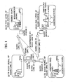
- Fig. 11 is a schematic diagram showing a communication control method according to the fourth embodiment;
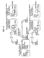
- Fig. 12 is a schematic diagram showing a process of a communication control system according to the fourth embodiment;
- Fig. 13 is a block diagram showing radio stations according to the fourth embodiment;
- Fig. 14 is a schematic diagram showing an overview of a communication control system according to the fifth embodiment;
- Fig. 15 is a block diagram showing radio stations according to the fifth embodiment;
- Fig. 16 is a schematic diagram showing assigned frequencies according to the first modification;
- Fig. 17 is a schematic diagram showing assigned frequencies according to the second modification;
- Fig. 18 is a schematic diagram showing assigned frequencies according to the third modification;
- Fig. 19 is a schematic diagram showing assigned frequencies according to the fourth modification;
- Fig. 20 is a schematic diagram showing assigned frequencies according to the fifth modification; and
- Fig. 21 is a schematic diagram showing assigned frequencies according to the fifth modification.
- Hereinafter, a communication control system according to the first embodiment will be described. Fig. 2 is a schematic diagram showing the overall configuration of a communication control system according to this embodiment. In Fig. 2, l1 through l5 indicate radio links. Accordingly,
radio stations 2 through 4 are interconnected by the radio links and theradio stations 2 through 4 transmit a notification signal that contains information regarding frequency band of radio links received at the radio station. - The
radio station 2 measures the frequency and reception power level of the radio signal received at a reception antenna when a new frequency band is assigned to the radio link l1 and transmits the measured information to a transmissionside radio station 1 as radio signal data. The transmissionside radio station 1 receives the radio signal data and acquires the reception power level of the notification signals transmitted by the respective radio stations and the information regarding frequency band contained in the notification signals. - The transmission
side radio station 1 can therefore recognize the frequency bands being used at other radio links and the interference that may affect the other radio links. For instance, interference whereby the radio link l1 may affect the radio link l4 can be recognized based on the reception power level of a notification signal l4' that is transmitted by theradio station 3, and the frequency band information of the radio link l4 can be acquired based on notification signal l4'. Further, the transmissionside radio station 1 can recognize a level of interference whereby the other radio links may affect theradio station 2 based on the radio signal data transmitted by theradio station 2. - The transmission
side radio station 1 can therefore determine a usable (assignable) frequency band according to the information acquired from the respective radio stations and the radio signal data transmitted by theradio station 2, both of which allow the estimation of interferences that may affect the other radio links. - Fig. 3 is a flowchart showing an assignment process of a frequency band according to this embodiment.
- As shown in Fig. 3, the
radio station 1 first initiates a radio link set up process (S100). Then an assignment request for a frequency band to a radio link arises, and the transmissionside radio station 1 transmits the request to the radio station 2 (S102). Theradio station 2 receives the request (S201). Theradio station 2 then measures the frequency of the radio signal and its reception power level on the traffic frequency band and transmits the measured frequency and the reception power level of the radio signal to the transmissionside radio station 1 as the radio signal data (S202). - On the other hand, the transmission
side radio station 1 acquires the reception power level of the notification signals that are transmitted by the other radio stations, and the information regarding the frequency band contained in the notification signal (S102), The transmissionside radio station 1 then receives the radio signal data from the radio station 2 (S103). Further, the transmissionside radio station 1 determines an assignable frequency band on the traffic frequency band based on the radio signal data, the reception power level of the notification signal and the information regarding the frequency band (S104). - Moreover, the transmission
side radio station 1 determines the transmission rate of the radio link to be set (S105), and selects a frequency band to be assigned to the radio link within the assignable frequency bands (S106). The transmissionside radio station 1 then transmits information indicating the selected frequency band to the radio station 2 (S107). Finally, the transmissionside radio station 1 transmits a radio signal using the selected frequency band (S108). Theradio station 2 receives the information indicating the selected frequency band (S203). Theradio station 2 then receives the radio signal from the transmissionside radio station 1 and transmits a notification signal regarding the selected frequency band to the other radio stations (S204), - Hereinafter, configuration of the notification signal will be described. Fig. 4 is a schematic diagram showing the configuration of the notification signal according to this embodiment. As shown in Fig. 4, the traffic frequency band and frequency band for control are assigned to the radio links l1 through l5. The
radio stations 1 through 4 determine a frequency band for the notification signal that is transmitted by the frequency band for control according to the frequency band of a radio signal received on the traffic frequency band. - For instance, as shown in Fig. 4 (a), f1 through f5 are set on the traffic frequency band and f1' through f5' are set on the frequency band for control, which correlates with f1 through f5, respectively. If f4 is used on the traffic frequency band, the notification signal is continuously transmitted using f4'. Further, if f1, f2 and f3 are used on the traffic frequency band, the notification signals are continuously transmitted using f1',f2, and f3'.
- The above described notification signal is transmitted as shown in Fig. 5. Fig. 5 is a schematic diagram showing the transmission and reception processes of the notification signal according to this embodiment. In Fig. 5, f1 through f5 indicate a traffic frequency band, and f1' through f5' indicate frequencies on the frequency band for control, which correlate with f1 through f5, respectively. In Fig. 5, bi-directional communication is being performed between the
radio station 1 andradio station 2. As shown in Fig. 5 (a) and (b), theradio stations 1 through 4 transmit the radio signal via the traffic frequency band and the notification signal via the frequency band for control, respectively. - Here, in a case where a radio link from the
radio station 3 to theradio station 4 is set, theradio station 4 measures the reception power level of radio signals on the traffic frequency band as shown in Fig. 5 (d), and theradio station 3 measures the reception power level of notification signals on the frequency band for control as shown in Fig. 5 (c). For instance, as shown in Fig. 5 (c), f1' that is transmitted by theradio station 2 has a greater reception power level than others at theradio station 3, and theradio station 3 recognizes that the radio link being set from theradio station 3 to theradio station 4 may adversely affect theradio station 2 if f1 is assigned to the radio link. - Accordingly, since the reception power level of interference at the
radio station 4 is below the threshold and the reception power level of the notification signal at theradio station 3 is below the threshold, theradio station 3 determines that f3 is an assignable frequency band for the radio link from theradio station 3 to theradio station 4. - Hereinafter, internal configuration of the radio station performing the above described communication control method will be described. Fig. 6 is a block diagram showing the radio station according to this embodiment. As shown in Fig. 6, a
radio station 100 and aradio station 200 have a TX/RX splitters antennas receivers demodulators dividers notification signal measurers radio signal measurers - Further, the
radio station 100 andradio station 200 havemultiplexers TX rate determiners frequency band controllers modulators notification signal generators combiners transmitters - It is to be noted that in the embodiments, the radio signal data measurer 107 acts as the radio signal data transmitter, the
notification signal generator 108 acts as the notification signal transmitter, and thefrequency band controller 109 acts as the frequency band determiner as well as the frequency band controller, respectively. - Firstly, a reception process at the
radio station 100 will be described. Theradio station 100 receives the radio signal from theradio station 200 via theantenna 101, and thereceiver 103 receives the radio signal through the TX/RX splitter 102. Thedemodulator 104 demodulates the received signal and forwards the signal to thedivider 105. Since the signal demodulated by thedemodulator 104 is configured with the information signal transmitted from theradio station 200 to theradio station 100 and a control signal that contains information regarding the radio signal received at theantenna 201 of theradio station 200, the signal is forwarded to thedivider 105 so as to divide the signal into the information signal and the control signal. The control signal is then forwarded to thefrequency band controller 109. - Further, the radio signal data measurer 107 measures the frequency and the reception power level of the radio signal received at the
antenna 101. Thenotification signal measurer 106 measures the reception power level of the notification signal on the frequency band for control, which is received at theantenna 101, and forwards the measured data that indicates the reception power level to thefrequency band controller 109. - Next, a transmission process of the
radio station 100 will be described. Themultiplexer 114 multiplexes the information regarding the reception power level of the radio signal that is measured by the radiosignal data measurer 107 and the information signal. Themultiplexer 114 forwards the multiplexed signal to theTX rate determiner 110 and themodulator 113. TheTX rate determiner 110 determines the transmission rate of the radio link to be set and forwards the determined rate to thefrequency band controller 109. - The
frequency band controller 109 controls a frequency band of the transmission radio link based on the information of the radio signal received at theradio station 200, the information of the notification signal measured at thenotification signal measurer 106 and the transmission rate determined by theTX rate determiner 110. Themodulator 113 then modulates the multiplexed signal to a radio signal according to the control of thefrequency band controller 109 and forwards the modulated signal to thecombiner 112. - Further, the
frequency band controller 109 forwards the information regarding the frequency band assigned to the radio link from theradio station 200 to theradio station 100, to thenotification signal generator 108. Thenotification signal generator 108 generates the notification signal corresponding to the frequency band of the radio link and forwards the notification signal to thecombiner 112. Thecombiner 112 combines the radio signal forwarded by themodulator 113 and the notification signal forwarded by thenotification signal generator 108, and forwards the combined signal to thetransmitter 111. The combined signal is then transmitted by theantenna 101 through the TX/RX splitter 102. - Hereinafter, the second embodiment of the present invention will be described. Fig. 7 is a schematic diagram showing an overview of a communication control system according to this embodiment. In Fig. 7, f1 and f2 indicate a frequency band on the traffic frequency band. The frequency bands are assigned to the radio links whereby bi-directional communication is being performed between the
radio station 1 and theradio station 2. - As shown in Fig. 7, the
radio station 1 and theradio station 2 transmit the notification signal that contains information regarding the frequency band of the received radio link, respectively. Theradio station 3 can therefore recognize the frequency bands being used at theradio stations radio station 3 can determine a frequency band, which will not interfere with the radio link between theradio station 1 and theradio station 2. - Especially, in this embodiment, each radio station (i.e.,
radio stations 1 through 4) modulates the information regarding the frequency band of the received radio link and transmits the modulated notification signal. The other radio stations demodulate the modulated notification signal so as to acquire the information contained in the notification signal. - Fig. 8 is a block diagram showing radio stations according to this embodiment. In order to accomplish the above-described feature, the radio station in the communication control system according to this embodiment has a notification signal demodulator 106', 107' instead of the
notification signal measurers notification signal generator - The
radio station 100 receives the radio signal from theradio station 200 via theantenna 101, and thereceiver 103 receives the radio signal through the TX/RX splitter 102. Thedemodulator 104 demodulates the received signal and forwards the signal to thedivider 105. Thedivider 105 divides the signal into the information signal and the control signal. The control signal is then forwarded to thefrequency band controller 109. - Further, the radio signal data measurer 107 measures the frequency and the reception power level of the radio signal. The notification signal demodulator 106' demodulates the notification signal, which is received at the
antenna 101. Further, the notification signal demodulator 106' acquires information regarding the received frequency band based on the notification signal and measures the reception power level of the notification signal. The information acquired from the notification signal and the measured reception power level are then forwarded to thefrequency band controller 109. - On the other hand, the
multiplexer 114 multiplexes the information regarding the reception power level of the radio signal that is measured by the radiosignal data measurer 107 and the information signal. Themultiplexer 114 forwards the multiplexed signal to theTX rate determiner 110 and themodulator 113. TheTX rate determiner 110 determines the transmission rate of the radio link to be set and forwards the determined rate to thefrequency band controller 109. - The
frequency band controller 109 controls a frequency band of the transmission radio link based on the information of the radio signal received at theradio station 200, the information of the notification signal measured at the notification signal demodulator 106' and the transmission rate determined by theTX rate determiner 110. Themodulator 113 then modulates the multiplexed signal to a radio signal according to the control of thefrequency band controller 109 and forwards the modulated signal to thecombiner 112. - Further, the
frequency band controller 109 forwards the information of the frequency band assigned to the radio link from theradio station 200 to theradio station 100 to the notification signal modulator 108'. The notification signal modulator 108' modulates the information regarding the frequency band of the radio link and forwards the notification signal to thecombiner 112. Thecombiner 112 combines the radio signal forwarded by themodulator 113 and the notification signal forwarded by the notification signal modulator 108', and forwards the combined signal to thetransmitter 111. The combined signal is then transmitted by theantenna 101 through the TX/RX splitter 102. It is to be noted that the same process is also performed in theradio station 200. - Fig. 9 is a schematic diagram showing a process of a communication control system according to the third embodiment. In Fig. 9, f1 through f5 show a frequency band on the traffic frequency band, and f1' through f5' show a frequency on the frequency band for control, which correlates with f1 through f5. Further, the frequency bands are assigned to radio links whereby bi-directional communications are being performed between the
radio station 1 and theradio station 4, and betweenradio station 2 and theradio station 3, respectively. - The
radio stations radio station 4 to theradio station 5 is assigned, theradio station 5 measures the reception power level of the received radio signals as shown in Fig. 9 (e), and theradio station 4 measures the reception power level of the notification signal for the certain period of time as shown in Fig. 9 (d). - The
radio station 4 determines that a frequency band is assignable, if its reception power level is less than a prescribed threshold during the certain period of time at theradio station 5 and the reception level of its notification signal does not exceed a prescribed threshold during the certain period of time at theradio station 4. That is, as shown in Fig. 9 (d) and (e), theradio station 4 determines a frequency band within f1 and f3, in both of which, the reception power level of the radio signal is less than the prescribed threshold. Further, since the reception power level of f3' (notification signal) does not exceed the prescribed threshold during the certain period of time whereas, the reception power level of f1' (notification signal) exceeds the threshold, theradio station 4 determines f3, which correlates with f3', as the assignable frequency band for the radio link. - As described heretofore, since each radio station randomly determines the transmission timing of the notification signal and continually transmits the signal, it is feasible to distinguish the frequency band, whose reception power level of the notification signal exceeds the prescribed threshold at the transmission timing during the certain period of time, from the frequency bands for which the notification signal is transmitted. Thus, the magnitude of interference caused by the radio link assignment can be examined more accurately.
- Fig. 10 is a schematic diagram showing a process of the communication control system according to modification of the third embodiment. In Fig. 10, f1 through f5 show a frequency band on the traffic frequency band. Further, the frequency bands are assigned to radio links whereby bi-directional communications are being performed between the
radio station 1 and theradio station 4, and betweenradio station 2 and theradio station 3, respectively. - In this modification, the
radio stations radio station 4 to theradio station 5 is assigned, theradio station 5 measures the reception power level of received radio signals as shown in Fig. 10 (e), and theradio station 4 measures the reception power level of the notification signal for the certain period of time as shown in Fig. 10 (d). - The
radio station 4 determines that a frequency band is assignable, if its reception power level is less than a prescribed threshold during the certain period of time at theradio station 5 and the reception level of its modulated notification signal does not exceed a prescribed threshold during the certain period of time at theradio station 4. As shown in Fig. 10 (d) and (e), theradio station 4 determines a frequency band within f1 and f3, in both of which, the reception power level of the radio signal is less than the prescribed threshold. Further, since the reception power level of the notification signal transmitted by theradio station 3 exceeds the threshold at theradio station 4 and f1 can be retrieved from the notification signal, theradio station 4 determines f3, which does not exceed the threshold as the assignable frequency band for the radio link. Thus, it is feasible to select a frequency band, in which the magnitude of interference caused by the other radio links is less than the prescribed threshold, and which may not greatly interfere with the other radio links. - Fig. 11 is a schematic diagram showing a communication control method according to this embodiment. In this embodiment, a transmission side radio station determines the transmission power level of the notification signal that is transmitted by the frequency band for control based on a carrier to interference ratio (hereinafter referred to as CIR).
- That is, as shown in Fig. 11 (a) and (b), the transmission power level is set according to the CIR. The notification signal is transmitted with the transmission power Pctb, which is calculated by the following formula.

- Here, CIRl means a CIR of a radio link, CIRreq means a required CIR for communication, and Ptb means a base transmission power level. Further, an upper limit is set for Pctb so as to limit the level.
- Fig. 12 is a schematic diagram showing a process of a communication control system according to this embodiment. In Fig. 12, f1 through f4 indicate a frequency band on the traffic frequency band. Further, the frequency bands are assigned to radio links whereby bi-directional communications are being performed between the
radio station 1 and theradio station 2, and between theradio station 5 and theradio station 6, respectively. - Since the
radio stations radio station 3 measures the reception power level of the notification signal. As a result, since theradio station 2 that has a smaller value of CIR, the reception power level of f1' is greater than f2' at theradio station 3. Therefore, f1 that correlates with f1' is not assigned to a radio link. This method can prevent a frequency band which may interfere with the radio link that has already been interfered with from being selected. - Fig. 13 is a block diagram showing radio stations according to this embodiment. In this embodiment,
CIR calculators radio station 100 andradio station 200, which are described in the first embodiment. - The
radio station 100 receives the radio signal from theradio station 200 via theantenna 101, and thereceiver 103 receives the radio signal through the TX/RX splitter 102. Thedemodulator 104 demodulates the received signal and forwards the signal to thedivider 105. Since the signal demodulated by thedemodulator 104 is configured with the information signal transmitted from theradio station 200 to theradio station 100 and a control signal that contains information regarding the radio signal received at theantenna 201, the signal is forwarded to thedivider 105 so as to divide the signal into the information signal and the control signal. The control signal is then forwarded to thefrequency band controller 109. Further, the radio signal data measurer 107 measures the frequency and the reception power level of the radio signal received at theantenna 101. Thenotification signal measurer 106 measures the reception power level of the notification signal in the frequency band for control, which is received at theantenna 101, and forwards the measured data that indicates the reception power level to thefrequency band controller 109. - The
CIR calculator 115 calculates interference included in the radio signal based on the radio signal retrieved from thereceiver 103 and the signal of information signal retrieved from thedemodulator 104, and forwards a value of CIR to thefrequency band controller 109. - On the other hand, the
multiplexer 114 multiplexes the information regarding the reception power level of the radio signal that is measured by the radiosignal data measurer 107 and the information signal. Themultiplexer 114 forwards the multiplexed signal to theTX rate determiner 110 and themodulator 113. TheTX rate determiner 110 determines the transmission rate of the radio link to be set and forwards the determined rate to thefrequency band controller 109. - The
frequency band controller 109 controls a frequency band of a transmission radio link based on the information regarding the interference received at theradio station 200, the information of the notification signal measured at thenotification signal measurer 106 and the transmission rate determined by theTX rate determiner 110. Themodulator 113 then modulates the multiplexed signal to a radio signal according to the control of thefrequency band controller 109 and forwards the modulated signal to thecombiner 112. - Further, the
frequency band controller 109 forwards the information regarding the frequency band assigned for the radio link from theradio station 200 to theradio station 100 to thenotification signal generator 108. Thenotification signal generator 108 generates the notification signal corresponding to the received frequency band of the radio link based on the value of the CIR forwarded by theCIR calculator 115. Thenotification signal generator 108 then forwards the generated notification signal to thecombiner 112. Thecombiner 112 combines the radio signal forwarded by themodulator 113 and the notification signal forwarded by thenotification signal generator 108, and forwards the combined signal to thetransmitter 111. The combined signal is then transmitted by theantenna 101 through the TX/RX splitter 102. It is to be noted that the same process is also performed in theradio station 200. - Fig. 14 is a schematic diagram showing an overview of a communication control system according to this embodiment. In Fig. 14, f1 through f5 indicate a frequency band on the traffic frequency band. Further, the frequency bands are assigned to radio links whereby bi-directional communications are being performed between the
radio station 1 and theradio station 2, and between theradio station 5 and theradio station 6, respectively. - In this embodiment, a transmission side radio station modulates the notification signal that contains a value of the calculated CIR and transmits the signal, and a reception side radio station retrieves the value of CIR by demodulating the received notification signal.
- Since the CIR at the
radio stations radio station 3, theradio station 3 determines an assignable frequency band using a propagation loss that is calculated based on the reception power level of the modulated notification signal, the information of the received frequency band contained in the notification signal and the value of the CIR. Thus, theradio station 3 can select a frequency band, which avoids that which has transmission quality whereby the radio link degrades below a prescribed threshold. - Fig. 15 is a schematic diagram showing radio stations according to this embodiment. Especially, in this embodiment, each radio station modulates the information regarding the frequency band of the received radio links, and transmits the modulated notification signal. Further, the radio station has a notification signal demodulator 106' which demodulates the notification signal so as to acquire the information regarding the frequency band, a
CIR calculator 115 which calculates the value of CIR, and a notification signal modulator 108' which modulates the notification signal according to the value of CIR. - The
radio station 100 receives the radio signal from theradio station 200 via theantenna 101, and thereceiver 103 receives the radio signal through the TX/RX splitter 102. Thedemodulator 104 demodulates the received signal and forwards the signal to thedivider 105. - Since the signal demodulated by the
demodulator 104 is configured with the information signal transmitted from theradio station 200 to theradio station 100 and a control signal that contains information regarding the radio signal received at theantenna 201, the signal is forwarded to thedivider 105 so as to divide the signal into the information signal and the control signal. - The control signal is then forwarded to the
frequency band controller 109. Further, the radio signal data measurer 107 measures the frequency and the reception power level of the radio signal received at theantenna 101. The notification signal demodulator 106' demodulates the notification signal, which is received at theantenna 101. Further, notification signal demodulator 106' acquires the information regarding the received frequency band and the value of CIR, and measures the reception power level of the notification signal. The information regarding the reception frequency band as well as the value of CIR and the measured reception power level are then forwarded to thefrequency band controller 109. - The
CIR calculator 115 calculates the interference included in the radio signal based on the radio signal retrieved from thereceiver 103 and the information signal retrieved form thedemodulator 104, and forwards the value of CIR to thefrequency band controller 109. - On the other hand, the
multiplexer 114 multiplexes the information regarding the reception power level of the radio signal that is measured by the radiosignal data measurer 107 and the information signal. Themultiplexer 114 forwards the multiplexed signal to theTX rate determiner 110 and themodulator 113. TheTX rate determiner 110 determines a transmission rate for the radio link to be set and forwards the determined rate to thefrequency band controller 109. - The
frequency band controller 109 controls a frequency band of the transmission radio link based on the information regarding the interference received at theradio station 200, the information of the notification signal measured at the notification signal demodulator 106' and the transmission rate determined by theTX rate determiner 110. Themodulator 113 then modulates the multiplexed signal to a radio signal according to the control of thefrequency band controller 109 and forwards the modulated signal to thecombiner 112. - Further, the
frequency band controller 109 forwards the information regarding the frequency band assigned for the radio link from theradio station 200 to theradio station 100 to the notification signal modulator 108'. The notification signal modulator 108' generates the notification signal that contains the value of CIR forwarded by theCIR calculator 115 and the information regarding the reception frequency band of the radio link, and modulates the notification signal. The notification signal modulator 108' then forwards the modulated notification signal to thecombiner 112. Thecombiner 112 combines the radio signal forwarded by themodulator 113 and the notification signal forwarded by the notification signal modulator 108', and forwards the combined signal to thetransmitter 111. The combined signal is then transmitted by theantenna 101 through the TX/RX splitter 102. It is to be noted that the same process is also performed in theradio station 200. - The present invention is not limited to the first through fifth embodiments described above and the following modifications can be made.
- Fig. 16 is a schematic diagram showing assigned frequencies according to this modification. In this modification, if frequency bands f2 and f5 are determined as assignable, the frequency band f2, of which the frequency is lower than f5, is assigned to a radio link using an appropriate embodiment as described above.
- Since assigning a frequency band, of which the frequency is as low as possible, to a radio link allows the effective use of frequencies, the total required frequency bandwidth is thus reduced.
- Fig. 17 is a schematic diagram showing assigned frequencies according to this modification. In this modification, if frequency bands f2 and f5 are determined as assignable, the frequency band f5, of which the frequency is higher than f2, is assigned to a radio link using an appropriate embodiment as described above.
- Since assigning a frequency band, of which the frequency is as high as possible, to a radio link allows the effective use of frequencies, the total required frequency bandwidth is thus reduced.
- Fig. 18 is a schematic diagram showing assigned frequencies according to this modification. In this modification, if frequency bands f2, f3 and f5 are determined as assignable, the frequency band f2, of which the reception level at a reception side radio station is lowest, is assigned to a radio link.
- This method reduces a situation where the level of interference power exceeds a prescribed threshold even if the condition of the interference varies, i.e., the level of the interference increases during communication.
- Fig. 19 is a schematic diagram showing assigned frequencies according to this modification. In this modification, if frequency bands f2, f3 and f5 are determined as assignable, the frequency band f5 is assigned to a radio link because the reception power level of the corresponding notification signal on the frequency band for control is lowest.
- Since interference that may affect other radio links can be minimized by assigning a frequency band, of which the notification signal has lower reception power level, to the radio link, this method reduces a situation whereby a radio link degrades below the prescribed transmission quality due to interference caused by assigning other radio links.
- Fig. 20 is a schematic diagram showing assigned frequencies according to this modification. In this modification, as shown in Fig. 20, a frequency band is assigned according to the volume of data to be transmitted in an assignable bandwidth.
- Further, as shown in Fig. 21, a couple of frequency bands may be assigned according to the volume of data to be transmitted as required. This method allows the effective use of frequencies even if a large volume of data is to be transmitted.
- Incidentally, although a case where the radio station acts as a radio base station is described in the above embodiments, the radio station may also act as a mobile station as well.
- As will be seen from the foregoing description, in the present invention, a notification signal which correlates with a reception frequency band is transmitted and the reception power level of the notification signal is measured at a transmission side radio station when radio communication is conducted between the transmission side radio station and a reception side radio station in a radio network in which a plurality of radio stations are deployed. Thus, the present invention prevents a frequency band that may greatly interfere with other radio links from being assigned, and an appropriate bandwidth can be assigned to respective radio links according to the volume of data to be transmitted.
- The invention has been described in detail by referring to the embodiments. It is obvious to those skilled in the art that the invention is not restricted to the embodiments mentioned above. The invention may be carried out as a corrected or modified embodiment not departing from the gist and scope specified by the scope of the claims of the patent. Therefore, the description of this specification aims at the representation of examples but does not have any limitation on the present invention.
Claims (18)
- A communication control method for conducting communication between a transmission side radio station and a reception side radio station in a radio network in which a plurality of the radio stations are deployed, comprising the steps of:(1) transmitting a notification signal that notifies information of a frequency of a radio link being used at a radio station;(2) measuring a reception power level of a radio signal received and detecting a frequency of the radio signal at the reception side radio station;(3) transmitting the reception power level and the frequency of the radio signal to the transmission side radio station;(4) measuring a reception power level of each of the notification signals and detecting the frequency of the radio link being used at each of the radio stations, which is notified by the notification signal, at the transmission side radio station; and(5) determining an assignable frequency band to be used between the transmission side radio station and the reception side radio station at the transmission side radio station based on the reception power level and the frequency of the radio signal, the reception power level of the notification signal and information contained in the notification signal.
- A communication control method according to claim 1, wherein the radio link is configured with a traffic frequency band that is used for transmission of an information signal and a frequency band for control that is used for a control signal,
the frequency of the radio link being used at the radio station at a step (1) is located in the traffic frequency band, and
the notification signal is transmitted using the frequency band for control. - A communication control method according to claim 2, wherein a frequency of the traffic frequency band correlates with a frequency of the frequency band for control, and
each of the radio stations detects the frequency of the notification signal in the frequency band for control so as to recognize the frequency being used in the traffic frequency band at the radio station that transmits the notification signal. - A communication control method according to claim 2, wherein each of the radio stations modulates the notification signal that contains information of the frequency being used in the traffic frequency band and transmits the modulated notification signal, and
other radio stations demodulate the modulated notification signal so as to acquire the information of the frequency being used in the traffic frequency band. - A communication control method according to claim 1, wherein each of the radio stations measures a carrier to interference ratio of the radio link being used, modulates the notification signal which has a power level corresponding to the measured carrier to interference ratio and transmits the modulated notification signal, and
other radio stations receive and demodulate the modulated notification signal so as to acquire the measured carrier to interference ratio. - A communication control method according to claim 1, wherein the transmission side radio station determines a transmission rate based on a volume of data to be transmitted and assigns a required frequency bandwidth to transmit the data by the determined transmission rate.
- A communication control system for conducting communication between a transmission side radio station and a reception side radio station in a radio network in which a plurality of the radio stations are deployed, comprising:a notification signal transmitter configured to transmit a notification signal that notifies information of a frequency of a radio link being used at a radio station;a notification signal measurer configured to measure a reception power level of the notification signal and to detect a frequency notified by the notification signal;a radio signal data transmitter configured to transmit a reception level and a frequency of the radio signal received at the reception side radio station;a frequency band determiner configured to determine an assignable frequency band to be used between the transmission side radio station and the reception side radio station based the reception power level and the frequency of the radio signal, the reception power level of the notification signal and information contained in the notification signal.
- A communication control system according to claim 7, wherein the radio link is configured with a traffic frequency band that is used for transmission of an information signal and a frequency band for control that is used for a control signal,
the frequency of the radio link being used at the radio station is located in the traffic frequency band, and
the notification signal transmitter transmits the notification signal using the frequency band for control. - A communication control system according to claim 8, wherein a frequency of the traffic frequency band correlates with a frequency of the frequency band for control, and
the notification signal measurer detects the frequency of the notification signal in the frequency band for control so as to recognize the frequency being used in the traffic frequency band at the radio station that transmits the notification signal. - A communication control system according to claim 8, further comprising:a notification signal modulator configured to modulate the notification signal that contains information of the frequency being used in the traffic frequency band and transmit the modulated notification signal, anda notification signal demodulator configured to demodulate the modulated notification signal so as to acquire the information of the frequency being used in the traffic frequency band.
- A communication control system according to claim 7, wherein the notification signal transmitter transmits the notification signal at a random interval within a prescribed time range.
- A communication control system according to claim 7, wherein the notification signal transmitter measures a carrier to interference ratio of the radio link being used and transmits the notification signal with a power level that corresponds to the measured carrier to interference ratio.
- A communication control system according to claim 7, wherein the notification signal modulator modulates the notification signal that contains the measured carrier to interference ratio and transmits the modulated notification signal, and
the notification signal demodulator demodulates the modulated notification signal so as to acquire the measured carrier to interference ratio. - A communication control system according to claim 7, further comprising:a transmission rate determiner configured to determine a transmission rate based on a volume of data to be transmitted, anda frequency band controller configured to assign a required frequency bandwidth to transmit the data by the determined transmission rate.
- A communication control system according to claim 7, wherein priority is given to a lower frequency in the assignable frequency band when a frequency is assigned to the radio link by the frequency band controller.
- A communication control system according to claim 7, wherein priority is given to a higher frequency in the assignable frequency band when a frequency is assigned to the radio link by the frequency band controller.
- A communication control system according to claim 7, wherein the frequency band controller assigns frequency bands that are contiguously located in the traffic frequency band to radio links.
- A communication control system according to claim 7, wherein the frequency band controller assigns a plurality of frequency bands to a radio link.
Applications Claiming Priority (2)
| Application Number | Priority Date | Filing Date | Title |
|---|---|---|---|
| JP2002061119A JP3857602B2 (en) | 2002-03-06 | 2002-03-06 | Communication control method and communication control system |
| JP2002061119 | 2002-03-06 |
Publications (2)
| Publication Number | Publication Date |
|---|---|
| EP1343338A1 true EP1343338A1 (en) | 2003-09-10 |
| EP1343338B1 EP1343338B1 (en) | 2005-10-12 |
Family
ID=27751150
Family Applications (1)
| Application Number | Title | Priority Date | Filing Date |
|---|---|---|---|
| EP03004883A Expired - Fee Related EP1343338B1 (en) | 2002-03-06 | 2003-03-06 | Communication control method and communication control system |
Country Status (5)
| Country | Link |
|---|---|
| US (1) | US7292824B2 (en) |
| EP (1) | EP1343338B1 (en) |
| JP (1) | JP3857602B2 (en) |
| CN (1) | CN1316758C (en) |
| DE (1) | DE60301811T2 (en) |
Cited By (5)
| Publication number | Priority date | Publication date | Assignee | Title |
|---|---|---|---|---|
| WO2006046307A1 (en) | 2004-10-29 | 2006-05-04 | Fujitsu Limited | Communication device by multicarrier transmission method and communication system |
| EP1952650A1 (en) * | 2005-11-07 | 2008-08-06 | Agency for Science, Technology and Research | Method and devices for determining available frequency ranges |
| EP1952649A1 (en) * | 2005-11-07 | 2008-08-06 | Agency for Science, Technology and Research | Methods and devices for allocating frequency ranges |
| WO2011017078A1 (en) * | 2009-07-27 | 2011-02-10 | Qualcomm Incorporated | Method and apparatus for managing flexible usage of unpaired frequencies |
| CN103260213A (en) * | 2004-10-29 | 2013-08-21 | 富士通株式会社 | Communication devices and communication system based on multi-carrier transmission mode |
Families Citing this family (22)
| Publication number | Priority date | Publication date | Assignee | Title |
|---|---|---|---|---|
| US7209716B2 (en) * | 2003-02-27 | 2007-04-24 | Ntt Docomo, Inc. | Radio communication system, radio station, and radio communication method |
| JP4522753B2 (en) * | 2004-06-11 | 2010-08-11 | 株式会社エヌ・ティ・ティ・ドコモ | Frequency selection device, radio communication system, and radio control channel setting method |
| CN103338098B (en) * | 2004-10-29 | 2016-12-28 | 富士通株式会社 | Communication means |
| CN101895498B (en) * | 2004-10-29 | 2016-03-02 | 富士通株式会社 | Based on communicator and the communication system of multicarrier transmission mode |
| CN102065052B (en) * | 2004-10-29 | 2013-04-24 | 富士通株式会社 | Communicator based on multi-carrier transmission mode |
| ES2356467T3 (en) * | 2004-12-14 | 2011-04-08 | Telecom Italia S.P.A. | PROCEDURE TO CONFIGURE A TELECOMMUNICATIONS NETWORK, TELECOMMUNICATIONS NETWORK AND CORRESPONDING MANAGEMENT ENTITIES. |
| US8045580B2 (en) | 2005-04-04 | 2011-10-25 | Nec Corporation | Band control method and communication apparatus |
| GB2426150B (en) * | 2005-05-12 | 2007-09-19 | Roke Manor Research | A method of controlling communication |
| CN100426697C (en) * | 2005-06-22 | 2008-10-15 | 中兴通讯股份有限公司 | Downlink power control method in multi-carrier cell |
| JP4856187B2 (en) * | 2006-10-13 | 2012-01-18 | 富士通株式会社 | Radio base station, relay station, and bandwidth allocation method |
| EP2059059B1 (en) | 2006-10-13 | 2013-12-25 | Fujitsu Limited | Radio base station and communication control method |
| US8705438B2 (en) * | 2007-07-10 | 2014-04-22 | Qualcomm Incorporated | Methods and apparatus for selecting and/or using a communications band for peer to peer signaling |
| US20090017838A1 (en) * | 2007-07-10 | 2009-01-15 | Qualcomm Incorporated | Methods and apparatus for selecting a communications band based on location information |
| US7899073B2 (en) * | 2007-07-10 | 2011-03-01 | Qualcomm Incorporated | Methods and apparatus for monitoring for signals and selecting and/or using a communications band based on the monitoring results |
| JP5115179B2 (en) * | 2007-12-20 | 2013-01-09 | 日本電気株式会社 | Wireless communication control device, wireless communication control system, wireless communication control method, wireless communication control program, and recording medium |
| US9001674B2 (en) * | 2008-11-14 | 2015-04-07 | Optis Cellular Technology, Llc | Method of sensing |
| EP2356843A1 (en) * | 2008-11-14 | 2011-08-17 | Telefonaktiebolaget L M Ericsson (PUBL) | A method of sensing in a radio system employing opportunistic spectrum access |
| ES2356002B1 (en) * | 2008-12-29 | 2012-02-27 | Vodafone España, S.A.U. | METHOD AND SYSTEM TO OPTIMIZE THE BAND WIDTH IN A LTE / GSM COMMUNICATION NETWORK. |
| CN102577555B (en) * | 2009-10-02 | 2015-09-16 | 富士通株式会社 | Wireless communications method in wireless communication system, base station apparatus, terminal installation and wireless communication system |
| WO2011104804A1 (en) * | 2010-02-25 | 2011-09-01 | 日本電気株式会社 | Signal processing circuit, wireless communication device, and signal processing method |
| JP5423499B2 (en) * | 2010-03-16 | 2014-02-19 | 富士通株式会社 | Base station apparatus, communication system, and communication system control method |
| JP5967521B2 (en) * | 2012-04-16 | 2016-08-10 | パナソニックIpマネジメント株式会社 | Communication network system, terminal device |
Citations (3)
| Publication number | Priority date | Publication date | Assignee | Title |
|---|---|---|---|---|
| EP0946072A1 (en) * | 1998-03-27 | 1999-09-29 | Nec Corporation | Method of preventing interference of adjacent frequencies in a cellular system by selection between adjacent carrier frequency and non-adjacent carrier frequency |
| WO2001024568A1 (en) * | 1999-09-30 | 2001-04-05 | Qualcomm Incorporated | Closed loop resource allocation in a high speed wireless communications network |
| US6351643B1 (en) * | 1996-08-28 | 2002-02-26 | Telefonaktiebolaget Lm Ericsson | Method and system for autonomously allocating a frequency hopping traffic channel in a private radio system |
Family Cites Families (3)
| Publication number | Priority date | Publication date | Assignee | Title |
|---|---|---|---|---|
| JPH05206933A (en) | 1992-01-27 | 1993-08-13 | Fujitsu Ltd | Radio channel allocation system |
| JP2000013853A (en) | 1998-06-22 | 2000-01-14 | Mitsubishi Electric Corp | Radio communication system and radio communication method |
| US6466793B1 (en) * | 1999-05-28 | 2002-10-15 | Ericsson Inc. | Automatic frequency allocation (AFA) for wireless office systems sharing the spectrum with public systems |
-
2002
- 2002-03-06 JP JP2002061119A patent/JP3857602B2/en not_active Expired - Lifetime
-
2003
- 2003-03-05 US US10/378,893 patent/US7292824B2/en not_active Expired - Fee Related
- 2003-03-06 EP EP03004883A patent/EP1343338B1/en not_active Expired - Fee Related
- 2003-03-06 CN CNB031202519A patent/CN1316758C/en not_active Expired - Fee Related
- 2003-03-06 DE DE60301811T patent/DE60301811T2/en not_active Expired - Lifetime
Patent Citations (3)
| Publication number | Priority date | Publication date | Assignee | Title |
|---|---|---|---|---|
| US6351643B1 (en) * | 1996-08-28 | 2002-02-26 | Telefonaktiebolaget Lm Ericsson | Method and system for autonomously allocating a frequency hopping traffic channel in a private radio system |
| EP0946072A1 (en) * | 1998-03-27 | 1999-09-29 | Nec Corporation | Method of preventing interference of adjacent frequencies in a cellular system by selection between adjacent carrier frequency and non-adjacent carrier frequency |
| WO2001024568A1 (en) * | 1999-09-30 | 2001-04-05 | Qualcomm Incorporated | Closed loop resource allocation in a high speed wireless communications network |
Cited By (31)
| Publication number | Priority date | Publication date | Assignee | Title |
|---|---|---|---|---|
| US8547924B2 (en) | 2004-10-29 | 2013-10-01 | Fujitsu Limited | Communications apparatus and communications system using multicarrier transmission mode |
| US8705480B2 (en) | 2004-10-29 | 2014-04-22 | Fujitsu Limited | Communications apparatus and communications system using multicarrier transmission mode |
| WO2006046307A1 (en) | 2004-10-29 | 2006-05-04 | Fujitsu Limited | Communication device by multicarrier transmission method and communication system |
| US8553640B2 (en) | 2004-10-29 | 2013-10-08 | Fujitsu Limited | Communications apparatus and communications system using multicarrier transmission mode |
| US9554385B2 (en) | 2004-10-29 | 2017-01-24 | Fujitsu Limited | Communications apparatus and communications system using multicarrier transmission mode |
| US9313790B2 (en) | 2004-10-29 | 2016-04-12 | Fujitsu Limited | Communications apparatus and communications system using multicarrier transmission mode |
| US9036593B2 (en) | 2004-10-29 | 2015-05-19 | Fijitsu Limited | Communications apparatus and communications system using multicarrier transmission mode |
| EP1816666A4 (en) * | 2004-10-29 | 2012-06-06 | Fujitsu Ltd | Communication device by multicarrier transmission method and communication system |
| US8750233B2 (en) | 2004-10-29 | 2014-06-10 | Fujitsu Limited | Communications apparatus and communications system using multicarrier transmission mode |
| US8705479B2 (en) | 2004-10-29 | 2014-04-22 | Fujitsu Limited | Communications apparatus and communications system using multicarrier transmission mode |
| US8363610B2 (en) | 2004-10-29 | 2013-01-29 | Fujitsu Limited | Communications apparatus and communications system using multicarrier transmission mode |
| US8472398B2 (en) | 2004-10-29 | 2013-06-25 | Fujitsu Limited | Communications apparatus and communications system using multicarrier transmission mode |
| US8503386B2 (en) | 2004-10-29 | 2013-08-06 | Fujitsu Limited | Communications apparatus and communications system using multicarrier transmission mode |
| CN103260213A (en) * | 2004-10-29 | 2013-08-21 | 富士通株式会社 | Communication devices and communication system based on multi-carrier transmission mode |
| US8599943B2 (en) | 2004-10-29 | 2013-12-03 | Fujitsu Limited | Communications apparatus and communications system using multicarrier transmission mode |
| CN103260213B (en) * | 2004-10-29 | 2017-03-01 | 富士通株式会社 | Communicator based on multicarrier transmission mode and communication system |
| EP1816666A1 (en) * | 2004-10-29 | 2007-08-08 | Fujitsu Ltd. | Communication device by multicarrier transmission method and communication system |
| EP2683108A1 (en) * | 2004-10-29 | 2014-01-08 | Fujitsu Limited | Communications apparatus and communications system using multicarrier transmission mode |
| EP2683106A1 (en) * | 2004-10-29 | 2014-01-08 | Fujitsu Limited | Communications apparatus and communications system using multicarrier transmission mode |
| EP2683107A1 (en) * | 2004-10-29 | 2014-01-08 | Fujitsu Limited | Communications apparatus and communications system using multicarrier transmission mode |
| US8638869B2 (en) | 2004-10-29 | 2014-01-28 | Fujitsu Limited | Communications apparatus and communications system using multicarrier transmission mode |
| US8693426B2 (en) | 2004-10-29 | 2014-04-08 | Fujitsu Limited | Communications apparatus and communications system using multicarrier transmission mode |
| EP1952650A1 (en) * | 2005-11-07 | 2008-08-06 | Agency for Science, Technology and Research | Method and devices for determining available frequency ranges |
| US8204071B2 (en) | 2005-11-07 | 2012-06-19 | Agency For Science, Technology And Research | Methods and devices for allocating frequency ranges |
| US8204072B2 (en) | 2005-11-07 | 2012-06-19 | Agency For Science, Technology And Research | Method and devices for determining available frequency ranges |
| EP1952649A4 (en) * | 2005-11-07 | 2011-04-06 | Agency Science Tech & Res | Methods and devices for allocating frequency ranges |
| EP1952650A4 (en) * | 2005-11-07 | 2011-04-06 | Agency Science Tech & Res | Method and devices for determining available frequency ranges |
| EP1952649A1 (en) * | 2005-11-07 | 2008-08-06 | Agency for Science, Technology and Research | Methods and devices for allocating frequency ranges |
| US8743749B2 (en) | 2009-07-27 | 2014-06-03 | Qualcomm Incorporated | Method and apparatus for managing flexible usage of unpaired frequencies |
| KR101470412B1 (en) * | 2009-07-27 | 2014-12-08 | 퀄컴 인코포레이티드 | Method and apparatus for managing flexible usage of unpaired frequencies |
| WO2011017078A1 (en) * | 2009-07-27 | 2011-02-10 | Qualcomm Incorporated | Method and apparatus for managing flexible usage of unpaired frequencies |
Also Published As
| Publication number | Publication date |
|---|---|
| CN1316758C (en) | 2007-05-16 |
| CN1442963A (en) | 2003-09-17 |
| JP2003264867A (en) | 2003-09-19 |
| JP3857602B2 (en) | 2006-12-13 |
| DE60301811T2 (en) | 2006-07-06 |
| US20040203967A1 (en) | 2004-10-14 |
| DE60301811D1 (en) | 2006-02-23 |
| US7292824B2 (en) | 2007-11-06 |
| EP1343338B1 (en) | 2005-10-12 |
Similar Documents
| Publication | Publication Date | Title |
|---|---|---|
| US7292824B2 (en) | Communication control method and communication control system | |
| CN109997404B (en) | Random access method for multi-parameter set operation | |
| EP0928074B1 (en) | Transmission power control in a CDMA/TDD radio communication system | |
| US5517675A (en) | Signal transmission synchronization in a communication system | |
| JP4806660B2 (en) | Wireless communication system and communication method thereof | |
| US9350464B2 (en) | Method and system for mitigating co-channel interference | |
| KR100621953B1 (en) | Communication channel setting method, communication controller, and radio communication system | |
| US10123213B2 (en) | Methods and devices for securing radio resources for an LTE-U data transmission | |
| CA2583075A1 (en) | Apparatus and method for receiving packet data on a subset of carrier frequencies in a wireless communication system | |
| EP2373096A2 (en) | Method for selecting a relay station | |
| US9485067B2 (en) | Pilot arrangement method in mobile radio communication system and transmitter/receiver adopting same | |
| EP0986192A2 (en) | Mobile station communication apparatus, base station communication apparatus and radio communication method for transmission power control | |
| EP1280284B1 (en) | Radio base station, method for controlling the same and program recorded medium | |
| US6639908B1 (en) | Method of facilitating transmission level measurement, and base station | |
| EP1448005A1 (en) | Communication terminal apparatus, base station apparatus and radio communication method | |
| US8559965B2 (en) | Radio base station device, radio terminal device, and radio communication system | |
| US7738438B2 (en) | Radio base system, channel allocation method and channel allocating program | |
| JPH02192231A (en) | Transmission power control system | |
| KR101742494B1 (en) | Wireless Ethernet transmission apparatus and method for traffic transmitting in the apparatus | |
| US20020128032A1 (en) | Radio communication system | |
| JP2005347846A (en) | Base station device and method for controlling the same | |
| GB2613971A (en) | Establishing a wireless connection with a mobile device | |
| JP5056893B2 (en) | Pilot arrangement method in mobile radio communication system and transmission / reception apparatus to which this method is applied | |
| JP2010041290A (en) | Wireless communication device | |
| MXPA01000354A (en) | Interference prevention in a radio communications system |
Legal Events
| Date | Code | Title | Description |
|---|---|---|---|
| PUAI | Public reference made under article 153(3) epc to a published international application that has entered the european phase |
Free format text: ORIGINAL CODE: 0009012 |
|
| 17P | Request for examination filed |
Effective date: 20030306 |
|
| AK | Designated contracting states |
Kind code of ref document: A1 Designated state(s): AT BE BG CH CY CZ DE DK EE ES FI FR GB GR HU IE IT LI LU MC NL PT RO SE SI SK TR |
|
| AX | Request for extension of the european patent |
Extension state: AL LT LV MK |
|
| 17Q | First examination report despatched |
Effective date: 20031216 |
|
| AKX | Designation fees paid |
Designated state(s): DE GB |
|
| GRAP | Despatch of communication of intention to grant a patent |
Free format text: ORIGINAL CODE: EPIDOSNIGR1 |
|
| GRAS | Grant fee paid |
Free format text: ORIGINAL CODE: EPIDOSNIGR3 |
|
| GRAA | (expected) grant |
Free format text: ORIGINAL CODE: 0009210 |
|
| AK | Designated contracting states |
Kind code of ref document: B1 Designated state(s): DE GB |
|
| REG | Reference to a national code |
Ref country code: GB Ref legal event code: FG4D |
|
| REF | Corresponds to: |
Ref document number: 60301811 Country of ref document: DE Date of ref document: 20060223 Kind code of ref document: P |
|
| PLBE | No opposition filed within time limit |
Free format text: ORIGINAL CODE: 0009261 |
|
| STAA | Information on the status of an ep patent application or granted ep patent |
Free format text: STATUS: NO OPPOSITION FILED WITHIN TIME LIMIT |
|
| 26N | No opposition filed |
Effective date: 20060713 |
|
| PGFP | Annual fee paid to national office [announced via postgrant information from national office to epo] |
Ref country code: GB Payment date: 20120301 Year of fee payment: 10 |
|
| PGFP | Annual fee paid to national office [announced via postgrant information from national office to epo] |
Ref country code: DE Payment date: 20120404 Year of fee payment: 10 |
|
| GBPC | Gb: european patent ceased through non-payment of renewal fee |
Effective date: 20130306 |
|
| REG | Reference to a national code |
Ref country code: DE Ref legal event code: R119 Ref document number: 60301811 Country of ref document: DE Effective date: 20131001 |
|
| PG25 | Lapsed in a contracting state [announced via postgrant information from national office to epo] |
Ref country code: DE Free format text: LAPSE BECAUSE OF NON-PAYMENT OF DUE FEES Effective date: 20131001 Ref country code: GB Free format text: LAPSE BECAUSE OF NON-PAYMENT OF DUE FEES Effective date: 20130306 |