EP1338330A2 - Apparatus for mixing and homogenizing emulsions - Google Patents
Apparatus for mixing and homogenizing emulsions Download PDFInfo
- Publication number
- EP1338330A2 EP1338330A2 EP03290291A EP03290291A EP1338330A2 EP 1338330 A2 EP1338330 A2 EP 1338330A2 EP 03290291 A EP03290291 A EP 03290291A EP 03290291 A EP03290291 A EP 03290291A EP 1338330 A2 EP1338330 A2 EP 1338330A2
- Authority
- EP
- European Patent Office
- Prior art keywords
- mixer
- rotor
- stage
- mixture
- stator
- Prior art date
- Legal status (The legal status is an assumption and is not a legal conclusion. Google has not performed a legal analysis and makes no representation as to the accuracy of the status listed.)
- Withdrawn
Links
Images


Classifications
-
- C—CHEMISTRY; METALLURGY
- C10—PETROLEUM, GAS OR COKE INDUSTRIES; TECHNICAL GASES CONTAINING CARBON MONOXIDE; FUELS; LUBRICANTS; PEAT
- C10L—FUELS NOT OTHERWISE PROVIDED FOR; NATURAL GAS; SYNTHETIC NATURAL GAS OBTAINED BY PROCESSES NOT COVERED BY SUBCLASSES C10G, C10K; LIQUEFIED PETROLEUM GAS; ADDING MATERIALS TO FUELS OR FIRES TO REDUCE SMOKE OR UNDESIRABLE DEPOSITS OR TO FACILITATE SOOT REMOVAL; FIRELIGHTERS
- C10L1/00—Liquid carbonaceous fuels
- C10L1/32—Liquid carbonaceous fuels consisting of coal-oil suspensions or aqueous emulsions or oil emulsions
- C10L1/328—Oil emulsions containing water or any other hydrophilic phase
-
- B—PERFORMING OPERATIONS; TRANSPORTING
- B01—PHYSICAL OR CHEMICAL PROCESSES OR APPARATUS IN GENERAL
- B01F—MIXING, e.g. DISSOLVING, EMULSIFYING OR DISPERSING
- B01F23/00—Mixing according to the phases to be mixed, e.g. dispersing or emulsifying
- B01F23/40—Mixing liquids with liquids; Emulsifying
- B01F23/41—Emulsifying
-
- B—PERFORMING OPERATIONS; TRANSPORTING
- B01—PHYSICAL OR CHEMICAL PROCESSES OR APPARATUS IN GENERAL
- B01F—MIXING, e.g. DISSOLVING, EMULSIFYING OR DISPERSING
- B01F27/00—Mixers with rotary stirring devices in fixed receptacles; Kneaders
- B01F27/27—Mixers with stator-rotor systems, e.g. with intermeshing teeth or cylinders or having orifices
- B01F27/271—Mixers with stator-rotor systems, e.g. with intermeshing teeth or cylinders or having orifices with means for moving the materials to be mixed radially between the surfaces of the rotor and the stator
-
- B—PERFORMING OPERATIONS; TRANSPORTING
- B01—PHYSICAL OR CHEMICAL PROCESSES OR APPARATUS IN GENERAL
- B01F—MIXING, e.g. DISSOLVING, EMULSIFYING OR DISPERSING
- B01F27/00—Mixers with rotary stirring devices in fixed receptacles; Kneaders
- B01F27/05—Stirrers
- B01F27/11—Stirrers characterised by the configuration of the stirrers
- B01F27/19—Stirrers with two or more mixing elements mounted in sequence on the same axis
- B01F27/191—Stirrers with two or more mixing elements mounted in sequence on the same axis with similar elements
Definitions
- the invention relates to a mixing and homogenization device intended for the production of high-speed emulsions, a process using this device, and a installation comprising such a device.
- Such a device is intended for the production of a mixture or an emulsion with from at least two fluids which are difficult to mix, the emulsion having a sufficient fineness and stability for certain industrial applications.
- the fuels concerned are typically liquid hydrocarbons such only petroleum derivatives (petrol, diesel, kerosene, fuel oils), derivatives of coal or gas, hydrocarbons of vegetable origin.
- petroleum derivatives such as petroleum derivatives (petrol, diesel, kerosene, fuel oils), derivatives of coal or gas, hydrocarbons of vegetable origin.
- emulsions which are extremely fine, typically below or close to one micron.
- Such a system includes a tank comprising the mixture, a mixer outside this tank, and pipes between the mixing tank and the mixer.
- the fluid is extracted from the mixing tank, transferred to the mixer, to be homogenized. After mixing, the fluid leaving the mixer is transferred to the tank.
- the invention aims to overcome the drawbacks of the prior art by proposing a device for the continuous production of a fine emulsion, which can be to do on a large scale, for operating costs and power used lower compared to conventional processes, in particular of the batch type.
- the invention also relates to the production of ultrafine emulsions whose diameter droplets is of the order of a micron, or even less, of the order of 200 nm.
- the invention also aims to better control the composition of the mixture and a greatly reduced deterioration of fragile components of the mixture.
- the invention further relates to a wide variety of industrial applications, in in the fields of chemistry, fuels, food.
- the stator typically comprises a fixing crown connecting the crown annular and the wall of the floor.
- the rotor is a paddle wheel comprising a transverse plate and a cylindrical bore receiving the shaft supporting the at least four blades on at least one side.
- the rotor is a four-blade turbine having a cylindrical bore receiving the shaft, mounted transversely on a circular plate, the cross section of the blades increasing in moving away from the axis substantially up to half the blades, then constant over the other half.
- the rotor is a four-blade turbine substantially trapezoidal, connected by a cylindrical bore, the cross-section transverse of the blades being increasing by moving away radially from the shaft.
- the dimension of the stator slots in the axial direction is typically two to ten times the size of the slits transversely to this axial direction.
- the space between the annular crown of the stator and the internal face of the wall of the stage is between 0.2 and once the dimension of the slots according to the axial direction.
- the segments extend parallel to the direction axial of the mixer, the end of the segments being free on the side opposite the fixing crown.
- the segments and the slots are inclined relative to to the axial direction by an angle of the order of 5 to 30 °.
- Each stage includes a zone of strong turbulence under the action of rotor / stator and a homogenization zone without particle coalescence between the zone of strong turbulence and the partition with the floor next, before transfer to the next floor.
- Each stage optimizes the quality (rate) of homogenization of the mixed.
- the particular choice of mixing mobiles at the rotor / stator level allows to multiply the number of passages of particles in the area of shear (stator slots and rotor blades) inside each bedroom.
- the mixer comprises deflocculation means in at least one mixing chamber intended to re-homogenize the flow and provide additional shear in the homogenization zone.
- the mixer comprises means of injection by introduction orifices of mixing components in the mixing stages.
- the mixer comprises external reinforcing collars to the periphery of the wall of the main body.
- the mixer includes means for controlling and regulating the speed of rotation of each rotor during mixing, the structure of each stator rotor being defined as a function of the desired shear stresses.
- the invention relates to a mixing installation comprising at least one mixer as described above.
- a zone of strong turbulence is created under the action of the rotor / stator and a homogenization zone without particle coalescence between the zone of strong turbulence and the partition with the floor next, before transfer to the next floor.
- the mixture of a stage is transferred, under the effect of the flow in this stage and the drive by the rotor of the following stage, towards the following stage.
- the components of the mixture are incorporated all at once in the first mixer stage or multi-stage mixer, the constituents more fragile being incorporated in the last stage (s) of the mixer.
- the emulsified mixture has a viscosity of the order of 1 mPa.s to 10Pa.s.
- the invention relates to the application of the method to the online production of detergent, resin, cosmetic emulsions, glues, oils, food derivatives.
- the invention relates to the application of the method to the online production of water emulsions in at least one chosen hydrocarbon in the group comprising fuel oil, diesel, fuel oil, petrol, kerosene, the water percentage of the mixture being from 1 to 15%.
- Mixer 1 is a multi-stage in-line homogenizer mixer.
- the mixer 1 comprises motorization means 2, a main body tubular 3 for mixing, a chassis 4, means 5 for inlet of fluids, means 6 for evacuating fluids.
- At least two fluids intended to be mixed in the mixer 3 are routed by the arrival means 5, pass through the main body 3 and are discharged from the mixer 1 by the discharge means 6.
- the mixer 1 is typically in a horizontal position.
- the mixer 1 comprises a mixing shaft 7 movable in rotation extending along the longitudinal X axis of the main body 3.
- the main body 3 has a circular section and comprises several 8 aligned compartments which form the stages 9 of the mixer. Each compartment or stage has a mixing chamber.
- the mixer 1 comprises in this embodiment four chambers 10, 11, 12, 13.
- the continuous phase of the mixture enters the chamber 10, the mixture in the form of an emulsion leaves the mixer 1 through the chamber 13.
- the main body 3 comprises a cylindrical wall 17 delimiting the chambers 10, 11, 12, 13.
- the inlet means 5 comprise on the one hand a flared supply 5a of the continuous phase, in the axial direction X.
- the means of arrival 5 on the other hand have side inlets 5b, 5c, 5d of fluids intended for be incorporated into the mixture, respectively introduced into the chambers 10, 11, 12, 13.
- each stage 9 also called dispersed phase
- the fluids introduced into each stage 9, also called dispersed phase are incorporated by incorporation orifices 14, 15, 16 respectively for the rooms 10, 11, 12.
- Stage 13 is the emulsion outlet stage obtained after mixing with a evacuation orifice 18 of the evacuation means 6.
- the mixer 1 also comprises reinforcing collars 19, 20, 21, 22, 23 fixed.
- the collar 19 forms the end wall of the chamber 10 at the entrance to the mixer 1.
- the reinforcing collar 23 is located at the extreme part of the chamber 13 from the mixer outlet 1.
- the collar 23 is mounted on a ring 24 of the mixer 1 using connecting bolts 25.
- the collars 20, 21 and 22 are located in the separation zone between the chambers, respectively 10 and 11 for the collar 20, 11 and 12 for the collar 21, 12 and 13 for the collar 22.
- the collars 20, 21, 22 are embedded in the cylindrical wall 17 which is thus divided into cylindrical sections, respectively the section 26 for the chamber 10, the section 27 for the chamber 11, the section 28 for the chamber 12, the section 29 for room 13.
- the mixer further comprises support rods 30, 31, 32, 33 connecting two by two respectively the collars 19, 20, 21, 22, 23.
- Each stage 9 comprises a device 34 of rotor / stator type.
- the four-stage mixer 1 thus comprises four rotor / stator devices, respectively 35 for room 10, 36 for room 11, 37 for the room 12, 38 for room 13.
- Each rotor / stator device 35, 36, 37, 38 comprises a rotor respectively 35a, 36a, 37a, 38a, and a stator respectively 35b, 36b, 37b, 38b.
- Each chamber 10, 11, 12, 13 thus comprises a first zone of turbulence comprising the rotor / stator device 34, and a second zone homogenization between the rotor / stator device 34 of this chamber, and the rotor / stator device 34 of the adjacent downstream chamber.
- the stator 36b is in one piece, and includes an annular crown 39 and a fixing crown 40.
- the annular crown 39 is in the form segments 41 spaced at regular circumferential intervals.
- the fixing ring 40 forms a ring anchored by a fixing portion 42 in the cylindrical wall 17, more precisely the section 27 of the chamber 11.
- the fixing portion 42 is thus contiguous with the fixing portion 43 of the collar support 20 located between the section 27 and the section 26 of the chamber 10.
- the annular ring 39 has slots 44 between the segments 41 extending axially, comprising one end 45 on the side of the crown attachment 40 and one end 46 on the side opposite to the attachment ring 40.
- the fixing ring 40 of the rotor 36b forms a partition wall between the rooms 10 and 11.
- proximal and distal For each room, we designate by the qualifiers "proximal” and “Distal”, the areas respectively close to a fixing ring 40 and moving away from this fixing ring 40.
- the end 45 of a segment 41 For example for the bedroom 11, the end 45 of a segment 41 is located in the proximal position while its end 46 is in a distal position.
- the rotor 36a is intended to be rotated by the mixing shaft 7.
- the rotor 36a is a wheel with blade which includes a transverse plate 48 supporting on each face 48a, 48b, blades 49, eight blades 49 on the variant shown.
- the plaque transverse 48 has an axial cylindrical bore 50 intended to receive the shaft 7, and integral with the shaft 7 during its rotation.
- the blades 49 are spaced from the axial tubular part 50, and each comprise a song 51a inclined with respect to the axial direction X by an angle of the order of 10 degrees, an edge 51b in the radial direction Y, and an axial edge 51c.
- the diameter of the annular crown 19 is slightly greater than the diameter of the plate 48, for example 125 mm, so as to allow the rotation of the rotor 36a.
- the edge 51c is perpendicular and tangent to the plate 48 to improve shearing through the slots 44 of the stator 36b.
- the stator 36b surrounds the rotor 36a.
- the annular crown 39 is spaced from a space 47, sufficiently small to the desired shear stresses of the cylindrical wall 17.
- the diameter of the chamber 11 is for example in this embodiment 180 mm. In certain embodiments the diameter of the mixer can vary from 80 to 400 mm.
- transverse plate 48 is spaced along the direction X of the face of the fixing ring 40 opposite, a distance d sufficient for allow the mixture to pass from the previous upstream chamber, the occurrence of chamber 10 for device 36, towards chamber 11.
- This distance d is in this example 20 mm, substantially equal to the distance axial edge 51c.
- the mixture flows while being stirred under the action of the rotation of the rotor 36a towards the downstream part of the chamber 11.
- the blades 49 located on the side of the face 48b of the plate 48 also project the mixture through the slots 44.
- the structure of the devices 35, 36, 37, 38 is identical.
- the circulation of the fluids in the mixer 1 is done in the manner next, choosing fuel oil as an example of a continuous phase.
- the continuous phase (or first fluid) enters the mixer 1 through the means 5 of arrival in room 10.
- a second fluid, water, intended to be mixed with the continuous phase is introduced into the chamber 10 through the orifice 14.
- the two fluids are mixed by the rotor 35a causing a shear of this mixture in the axial direction and in the radial direction.
- the blades 49 of the rotor 35a project the fluids stirred in the radial direction through the slots 44 of the annular crown 39 of the stator 35b, towards the space 47.
- the rotor / stator device 35 allows the fluids to be mixed in the chamber 10, with a direction of flow of the mixture towards the next chamber 11.
- a deflocculating turbine 65 is placed in the chamber 10 after the device rotor / stator, so as to continue mixing the mixture in the area of the room 10.
- the mixture thus obtained of the first fluid and the second fluid is intended to pass into the next chamber 11, opening at the level of the device of the rotor / stator 36 of this chamber 11.
- the rotor 36a of chamber 11 stirs the mixture and directs it radially through the slots 44 of the crown ring 39 of stator 36b. Then the mixture goes according to the direction flow to the next room 12.
- a third fluid intended to be incorporated into the mixture of the first two fluids, can be introduced into compartment 11 through port 15. According to a variant this third fluid is the same as the second fluid.
- the mixture of the first, second and third fluids is then transferred to chamber 12, stirred by the rotor / stator device 37 in a similar manner, with possible incorporation of a fourth fluid which may be different or identical to the second and third fluids of chambers 10 and 11.
- the mixture then passes through the fourth and last chamber 13 of the mixer. It is stirred by the rotor / stator 38, a last fluid which can be introduced through an orifice 17 to be incorporated into the mixture. This latter fluid is typically more fragile than the previous fluid (s).
- the mixture is then evacuated via the evacuation conduit 18 of the means evacuation 6.
- the embodiment described is typically used for mixtures of the type water / oil.
- Such a mixer is also suitable for a water / milk powder mixture.
- the particle size of the emulsion obtained is of the order of ⁇ m.
- the rotor stator devices 35,36,37,38 are as in the first mode of identical realization between them. We therefore describe, for example, the stator rotor 36.
- the rotor 36a comprises a plate bottom 48 'supporting four blades 51 which are interconnected by a bore cylindrical hollow 50 'able to receive the axis 7.
- the cylindrical bore 50' comprises orifices 52 for means for fixing the bore 50 'to the shaft 7.
- Each blade 51 includes a bulged end portion 53 close to the cylindrical bore 50 'and a substantially flat end portion 54.
- each blade 51 is straight.
- the free radial edge 56 has a section 57 parallel to the plate bottom 48 and a section 58 inclined with respect to the section 57 by an angle of the order 30 degrees.
- the tangent free edges 55 of the blades 51 are spaced apart by a angle of around 90 degrees.
- the free edge 56 of the blades 51 when the rotor is mounted on the shaft, is in proximal position, on the side of the fixing ring 48, the base plate 48 being in the distal position, on the stator rotor side according to 37. In the position of mounting, the free edge 55 is opposite and parallel to the segments 41.
- the length of the free edge 56 in the direction X is substantially equal to the length of the segments 41.
- the circumference of the base plate 48 'and the ends 46 of segments 41 are substantially in the same plane.
- the structure of the stator 36 is different from that of the embodiment described above.
- the one-piece stator 36b ( Figures 5a, 5b) always includes a crown annular 39 and a fixing ring 40. However, instead of segments 41 spaced and straight, the annular ring 39 comprises segments spaced 59 connected together at their distal extreme part by a distal ring 60.
- the circumferentially spaced segments 59 are parallel to each other and inclined with respect to the axial direction by an angle of the order of 30 degrees.
- the annular crown 39 comprises for example 16 or 24 segments.
- the rotor 36a comprises four blades 61 connected around a cylindrical portion 62 receiving the shaft 7, the section of blades being increasing from the cylindrical portion 62 towards the free edge 63 of the blades 61.
- the rotor 36a does not include a bottom plate.
- the song 63a inclined by about 10 ° to the east radial direction, in the position of mounting on the shaft located in the proximal position, i.e. on the side of the fixing crown 40 of stator 36b.
- the structure of the devices rotor / stator 34 varies between chambers 10, 11, 12, 13.
- inlet chamber 10 and outlet chamber 13 may include a downstream pumping turbine.
- the residence time in the mixing zone is extremely short, which allows fine emulsions to be produced on large scales at a cost lower operating procedures compared to conventional methods.
- the power required by the mixer typically from 0.03 to 0.08 kW / kg of product, is less than that of a batch system.
- rotor / stator can be used, ranging from laboratory with a capacity of a few liters, foam concentrates for tanks of 1000 liters.
- the viscosity range accepted by the mixer is quite wide, ranging from 1 mPa.s to 10Pa.s.
- the different products to be mixed may have different physical properties as well as a high viscosity ratio, around 1000.
- the distribution of the product is optimized and the dosage is easier since each stage of the mixer has a valve introduction.
- the incorporation of the products is then done directly in the mixing zone, which allows optimal work of the different tools.
- this modularity of the exchanger makes it possible to limit the shearing of sensitive products by incorporating them on the top floor.
- the dosage of the components of the mixture makes it possible to obtain online stable emulsions without the need for recycling, and the mixer allows obtain a very good distribution of the product under the best conditions taking into account the physical characteristics of the product while reducing energy consumption compared to conventional methods of manufacturing, so as to obtain a wide field of application.
Landscapes
- Chemical & Material Sciences (AREA)
- Chemical Kinetics & Catalysis (AREA)
- Oil, Petroleum & Natural Gas (AREA)
- Engineering & Computer Science (AREA)
- General Chemical & Material Sciences (AREA)
- Organic Chemistry (AREA)
- Mixers Of The Rotary Stirring Type (AREA)
Abstract
Description
L'invention concerne un dispositif de mélange et d'homogénéisation destiné à la productions d'émulsions à débit élevé, un procédé utilisant ce dispositif, et une installation comprenant un tel dispositif.The invention relates to a mixing and homogenization device intended for the production of high-speed emulsions, a process using this device, and a installation comprising such a device.
Un tel dispositif est destiné à la production d'un mélange ou d'une émulsion à partir d'au moins deux fluides difficiles à mélanger, l'émulsion présentant une finesse et une stabilité suffisantes pour certaines applications industrielles.Such a device is intended for the production of a mixture or an emulsion with from at least two fluids which are difficult to mix, the emulsion having a sufficient fineness and stability for certain industrial applications.
Par exemple, on souhaite obtenir des émulsions très fines à partir de corps gras, dans le domaine des détergents, des résines, des colles, des cosmétiques, pour certains produits alimentaires. Certaines applications concernent également la réduction de taille des particules dans le cas de pâtes pigmentaires.For example, we want to obtain very fine emulsions from bodies oily, in the field of detergents, resins, adhesives, cosmetics, for certain food products. Some applications also relate to the reduction in particle size in the case of pasta pigmentary.
Par ailleurs, dans le domaine des combustibles, on cherche à obtenir des émulsions très fines incorporant de l'eau afin de limiter les coûts, la pollution, l'utilisation de réserves naturelles.Furthermore, in the field of fuels, it is sought to obtain very fine emulsions incorporating water to limit costs, pollution, the use of nature reserves.
Les combustibles concernés sont typiquement des hydrocarbures liquides tels que des dérivés de pétrole (essence, gazole, kérosène, mazouts), des dérivés de charbon ou de gaz, des hydrocarbures d'origine végétale. Pour de tels combustibles émulsionnés, un manque de stabilité se traduit par une séparation du produit en phases, pouvant affecter le stockage et certaines étapes de procédés utilisant ces produits.The fuels concerned are typically liquid hydrocarbons such only petroleum derivatives (petrol, diesel, kerosene, fuel oils), derivatives of coal or gas, hydrocarbons of vegetable origin. For such emulsified fuels, lack of stability results in separation of the product in phases, which may affect storage and certain stages of processes using these products.
On recherche en outre pour certaines applications des émulsions extrêmement fines, typiquement inférieures ou voisines du micron.In addition, for certain applications, emulsions which are extremely fine, typically below or close to one micron.
On connaít déjà des systèmes de mélange de type batch destinés à la production d'émulsions fines. Typiquement, un tel système comprend une cuve comprenant le mélange, un mélangeur à l'extérieur de cette cuve, et des canalisations entre la cuve de mélange et le mélangeur. We already know batch type mixing systems for the production of fine emulsions. Typically, such a system includes a tank comprising the mixture, a mixer outside this tank, and pipes between the mixing tank and the mixer.
Le fluide est extrait de la cuve de mélange, transféré vers le mélangeur, pour être homogénéisé. Après mélange, le fluide en sortie de mélangeur est transféré vers la cuve.The fluid is extracted from the mixing tank, transferred to the mixer, to be homogenized. After mixing, the fluid leaving the mixer is transferred to the tank.
On répète cette opération un certain nombre de fois, jusqu'à ce que le contenu de la cuve soit une émulsion fine présentant les caractéristiques souhaitées.This is repeated a number of times, until the content of the tank or a fine emulsion having the desired characteristics.
Un tel système présente plusieurs inconvénients, notamment :
- une puissance nécessitée par le mélangeur élevée, pour mélanger à chaque passe le fluide de manière à obtenir une émulsion ;
- des phénomènes de coalescence dans la cuve de fluides ;
- l'encombrement d'une telle installation ;
- une altération des composants fragiles du mélange.
- a high power required by the mixer, to mix the fluid at each pass so as to obtain an emulsion;
- coalescence phenomena in the fluid tank;
- the size of such an installation;
- alteration of the fragile components of the mixture.
L'invention vise à pallier les inconvénients de l'art antérieur en proposant un dispositif permettant une production en continu d'une émulsion fine, pouvant se faire à grande échelle, pour des coûts opératoires et une puissance utilisée moindres par rapport aux procédés classiques, notamment de type batch.The invention aims to overcome the drawbacks of the prior art by proposing a device for the continuous production of a fine emulsion, which can be to do on a large scale, for operating costs and power used lower compared to conventional processes, in particular of the batch type.
L'invention vise également la production d'émulsions ultrafines dont le diamètre des gouttelettes est de l'ordre du micron, voire moins, de l'ordre de 200 nm.The invention also relates to the production of ultrafine emulsions whose diameter droplets is of the order of a micron, or even less, of the order of 200 nm.
L'invention vise par ailleurs un meilleur contrôle de la composition du mélange et une altération fortement réduite de composants fragiles du mélange.The invention also aims to better control the composition of the mixture and a greatly reduced deterioration of fragile components of the mixture.
L'invention vise en outre une grande diversité d'applications industrielles, dans des domaines de la chimie, des combustibles, alimentaires.The invention further relates to a wide variety of industrial applications, in in the fields of chemistry, fuels, food.
A cet effet, l'invention propose selon un premier aspect un dispositif de rotor stator d'un mélangeur destiné à la production en continu d'émulsions fines, à partir d'au moins deux fluides difficiles à mélanger, le mélangeur comprenant au moins un étage de mélange, les étages étant séparés entre eux par des moyens formant cloison ménageant au moins une zone de passage du mélange, chaque étage comprenant :
- un rotor monté sur un axe support et comportant des pales de mélange exerçant des forces de cisaillement sur le mélange dans la direction axiale et dans la direction radiale ;
- un stator comportant une couronne annulaire entourant le rotor, située à une faible distance de la face interne de la paroi de l'étage, présentant des segments espacés circonférentiellement par des fentes de manière à définir des ouvertures, parallèles entre elles, et telles que le mélange projeté par le rotor selon la direction radiale à travers les ouvertures subit un cisaillement selon cette direction radiale.
- a rotor mounted on a support axis and comprising mixing blades exerting shear forces on the mixture in the axial direction and in the radial direction;
- a stator comprising an annular ring surrounding the rotor, located a short distance from the internal face of the stage wall, having segments spaced circumferentially by slots so as to define openings, parallel to each other, and such that the mixture projected by the rotor in the radial direction through the openings undergoes shearing in this radial direction.
Le stator comprend typiquement une couronne de fixation reliant la couronne annulaire et la paroi de l'étage.The stator typically comprises a fixing crown connecting the crown annular and the wall of the floor.
Selon un mode de réalisation, le rotor est une roue à aube comprenant une plaque transversale et un alésage cylindrique recevant l'arbre supportant au moins quatre pales sur au moins une face.According to one embodiment, the rotor is a paddle wheel comprising a transverse plate and a cylindrical bore receiving the shaft supporting the at least four blades on at least one side.
Selon un autre mode de réalisation, le rotor est une turbine à quatre pales comportant un alésage cylindrique recevant l'arbre, montées transversalement sur une plaque circulaire, la section transversale des pales étant croissante en s'éloignant de l'axe sensiblement jusqu'à la moitié des pales, puis constante sur l'autre moitié.According to another embodiment, the rotor is a four-blade turbine having a cylindrical bore receiving the shaft, mounted transversely on a circular plate, the cross section of the blades increasing in moving away from the axis substantially up to half the blades, then constant over the other half.
Selon un autre mode de réalisation, le rotor est une turbine à quatre pales sensiblement trapézoïdales, reliées par un alésage cylindrique, la section transversale des pales étant croissante en s'éloignant radialement de l'arbre.According to another embodiment, the rotor is a four-blade turbine substantially trapezoidal, connected by a cylindrical bore, the cross-section transverse of the blades being increasing by moving away radially from the shaft.
La dimension des fentes du stator selon la direction axiale est typiquement deux à dix fois supérieure à la dimension des fentes transversalement à cette direction axiale. The dimension of the stator slots in the axial direction is typically two to ten times the size of the slits transversely to this axial direction.
L'espace entre la couronne annulaire du stator et la face interne de la paroi de l'étage est compris entre 0.2 et une fois la dimension des fentes selon la direction axiale.The space between the annular crown of the stator and the internal face of the wall of the stage is between 0.2 and once the dimension of the slots according to the axial direction.
Selon une réalisation, les segments s'étendent parallèlement à la direction axiale du mélangeur, l'extrémité des segments étant libre du côté opposé à la couronne de fixation.According to one embodiment, the segments extend parallel to the direction axial of the mixer, the end of the segments being free on the side opposite the fixing crown.
Selon une autre réalisation, les segments et les fentes sont inclinés par rapport à la direction axiale d'un angle de l'ordre de 5 à 30°.According to another embodiment, the segments and the slots are inclined relative to to the axial direction by an angle of the order of 5 to 30 °.
Selon un second aspect l'invention concerne un mélangeur comprenant :
- un corps principal de mélange tubulaire comportant la paroi externe du mélangeur, le mélangeur comprenant au moins un étage de mélange, les étages étant alignés en série selon la direction d'écoulement et séparés entre eux par une cloison de séparation ménageant au moins une zone de passage du mélange ;
- des moyens de motorisation et de commande de la rotation de l'axe support des outils de mélange ;
- des moyens d'arrivée au mélangeur des constituants du mélange et des moyens d'évacuation du mélange du mélangeur ;
- a main tubular mixing body comprising the external wall of the mixer, the mixer comprising at least one mixing stage, the stages being aligned in series in the direction of flow and separated from each other by a partition separating at least one zone of passage of the mixture;
- means for motorizing and controlling the rotation of the support axis of the mixing tools;
- means for supplying the components of the mixture to the mixer and means for discharging the mixture from the mixer;
Chaque étage comprend une zone de forte turbulence sous l'action du rotor/stator et une zone d'homogénéisation sans coalescence des particules entre la zone de forte turbulence et la cloison de séparation avec l'étage suivant, avant le transfert à l'étage suivant. Each stage includes a zone of strong turbulence under the action of rotor / stator and a homogenization zone without particle coalescence between the zone of strong turbulence and the partition with the floor next, before transfer to the next floor.
Chaque étage permet d'optimiser la qualité (le taux) d'homogénéisation du mélange. Le choix particulier des mobiles de mélange au niveau du rotor/stator permet de multiplier le nombre de passages des particules dans la zone de cisaillement (fentes du stator et pales du rotor) à l'intérieur même de chaque chambre.Each stage optimizes the quality (rate) of homogenization of the mixed. The particular choice of mixing mobiles at the rotor / stator level allows to multiply the number of passages of particles in the area of shear (stator slots and rotor blades) inside each bedroom.
On peut donc obtenir, pour un nombre réduit d'éléments de mélange, un temps de séjour du produit supérieur grâce à la recirculation interne à chaque chambre.It is therefore possible to obtain, for a reduced number of mixing elements, a time of stay of the superior product thanks to the internal recirculation at each bedroom.
Selon une réalisation, le mélangeur comprend des moyens de défloculation dans au moins une chambre de mélange destinés à réhomogénéiser le flux et apporter un cisaillement supplémentaire dans la zone d'homogénéisation.According to one embodiment, the mixer comprises deflocculation means in at least one mixing chamber intended to re-homogenize the flow and provide additional shear in the homogenization zone.
Le mélangeur comprend des moyens d'injection par des orifices d'introduction de composants du mélange dans les étages de mélange.The mixer comprises means of injection by introduction orifices of mixing components in the mixing stages.
Selon une réalisation, le mélangeur comprend des colliers externes de renfort à la périphérie de la paroi du corps principal.According to one embodiment, the mixer comprises external reinforcing collars to the periphery of the wall of the main body.
Le mélangeur comprend des moyens de contrôle et de régulation de la vitesse de rotation de chaque rotor lors du mélange, la structure de chaque rotor stator étant définie en fonction des contraintes de cisaillement souhaitées.The mixer includes means for controlling and regulating the speed of rotation of each rotor during mixing, the structure of each stator rotor being defined as a function of the desired shear stresses.
Selon un troisième aspect l'invention concerne une installation de mélange comprenant au moins un mélangeur tel que décrit précédemment.According to a third aspect the invention relates to a mixing installation comprising at least one mixer as described above.
Selon un quatrième aspect l'invention concerne un procédé d'homogénéisation en continu destiné à la production à débit élevé d'émulsions fines mettant en oeuvre un tel mélangeur et comprenant les étapes suivantes :
- a) introduction des fluides par lesdits moyens d'entrée dans un étage d'entrée du mélangeur ;
- b) mélange des matières premières dans le premier étage à l'aide du dispositif rotor/stator, de manière à exercer des forces de cisaillement dans la direction axiale et la direction radiale du mélangeur ;
- c) transfert du mélange selon l'axe du mélangeur jusque dans l'étage suivant ;
- d) répétition des étapes b) et c) pour chaque étage du mélangeur, le mélange transféré subissant au moins un cycle de mélange à chaque étage avant le transfert à l'étage suivant ;
- e) évacuation du mélange homogénéisé, de manière à obtenir des émulsions ultrafines stables, et dont le diamètre des particules est contrôlé, de l'ordre de 100 nanomètres à plusieurs microns.
- a) introduction of the fluids by said input means into an input stage of the mixer;
- b) mixing the raw materials in the first stage using the rotor / stator device, so as to exert shear forces in the axial direction and the radial direction of the mixer;
- c) transfer of the mixture along the axis of the mixer to the next stage;
- d) repeating steps b) and c) for each stage of the mixer, the transferred mixture undergoing at least one mixing cycle at each stage before transfer to the next stage;
- e) evacuation of the homogenized mixture, so as to obtain stable ultrafine emulsions, the particle diameter of which is controlled, of the order of 100 nanometers to several microns.
Dans chaque étage on crée une zone de forte turbulence sous l'action du rotor/stator et une zone d'homogénéisation sans coalescence des particules entre la zone de forte turbulence et la cloison de séparation avec l'étage suivant, avant le transfert à l'étage suivant.In each stage, a zone of strong turbulence is created under the action of the rotor / stator and a homogenization zone without particle coalescence between the zone of strong turbulence and the partition with the floor next, before transfer to the next floor.
Le mélange d'un étage est transféré, sous l'effet de l'écoulement dans cet étage et de l'entraínement par le rotor de l'étage suivant, vers l'étage suivant.The mixture of a stage is transferred, under the effect of the flow in this stage and the drive by the rotor of the following stage, towards the following stage.
Les composants du mélange sont incorporés en une seule fois dans le premier étage du mélangeur ou à plusieurs étages du mélangeur, les constituants les plus fragiles étant incorporés dans le ou les derniers étages du mélangeur.The components of the mixture are incorporated all at once in the first mixer stage or multi-stage mixer, the constituents more fragile being incorporated in the last stage (s) of the mixer.
Le mélange émulsionné a une viscosité de l'ordre de 1 mPa.s à 10Pa.s.The emulsified mixture has a viscosity of the order of 1 mPa.s to 10Pa.s.
Selon un cinquième aspect l'invention concerne l'application du procédé à la production en ligne d'émulsions de type détergents, résines, cosmétiques, colles, huiles, dérivés alimentaires.According to a fifth aspect, the invention relates to the application of the method to the online production of detergent, resin, cosmetic emulsions, glues, oils, food derivatives.
Selon un sixième aspect l'invention concerne l'application du procédé à la production en ligne d'émulsions d'eau dans au moins un hydrocarbure choisi dans le groupe comprenant le fioul, le gazole, le mazout, l'essence, le kérosène, le pourcentage en eau du mélange étant de 1 à 15%.According to a sixth aspect the invention relates to the application of the method to the online production of water emulsions in at least one chosen hydrocarbon in the group comprising fuel oil, diesel, fuel oil, petrol, kerosene, the water percentage of the mixture being from 1 to 15%.
Selon un septième aspect l'invention concerne un produit obtenu par la mise en oeuvre du procédé comprenant :
- 1 à 15% d'eau ;
- 0 à 10% d'un système émulsifiant ;
- le complément à 100% d'hydrocarbures choisis dans le groupe comprenant le fioul, le gazole, le mazout, l'essence, le kérosène ; la taille des particules du mélange obtenu étant de l'ordre de 200 nm à quelques micromètres, et le mélange étant stable de manière à éviter une coalescence perturbant son utilisation.
- 1 to 15% water;
- 0 to 10% of an emulsifying system;
- the complement to 100% of hydrocarbons chosen from the group comprising fuel oil, diesel, fuel oil, petrol, kerosene; the particle size of the mixture obtained being of the order of 200 nm to a few micrometers, and the mixture being stable so as to avoid a coalescence disrupting its use.
D'autres objets et avantages de l'invention apparaítront au cours de la description qui va être faite en référence aux figures annexées dans lesquelles :
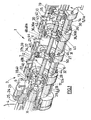
- la figure 1 est une vue écorchée du mélangeur à plusieurs étages selon l'invention ;
- la figure 2 est une vue en agrandissement de la figure 1 au niveau des chambres de mélange 10 à 12 ;
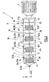
- la figure 3 est une vue générale schématique en coupe longitudinale d'un mélangeur selon l'invention ;
- les figures 4a, 4b sont des vues ,respectivement du stator et du rotor d'un étage, selon un deuxième mode de réalisation ;
- les figures 5a, 5b et 5c représentent des variantes de réalisation du rotor/stator d'un étage du mélangeur selon un troisième mode de réalisation de l'invention.
- Figure 1 is a cutaway view of the multi-stage mixer according to the invention;
- Figure 2 is an enlarged view of Figure 1 at the mixing
chambers 10 to 12; - Figure 3 is a schematic general view in longitudinal section of a mixer according to the invention;
- Figures 4a, 4b are views, respectively of the stator and the rotor of a stage, according to a second embodiment;
- Figures 5a, 5b and 5c show alternative embodiments of the rotor / stator of a stage of the mixer according to a third embodiment of the invention.
On décrit un premier mode de réalisation du mélangeur selon l'invention puis différentes variantes de réalisation plus spécifiquement destinées à telle ou telle application.A first embodiment of the mixer according to the invention is described, then different embodiments more specifically intended for such and such application.
Le mélangeur 1 est un mélangeur homogénéiseur en ligne multiétagé. Mixer 1 is a multi-stage in-line homogenizer mixer.
Le mélangeur 1 comprend des moyens de motorisation 2, un corps principal
tubulaire 3 de mélange, un châssis 4, des moyens d'arrivée 5 de fluides, des
moyens d'évacuation 6 de fluides.The mixer 1 comprises motorization means 2, a
Au moins deux fluides destinés à être mélangés dans le mélangeur 3 sont
acheminés par les moyens d'arrivée 5, transitent dans le corps principal 3 et
sont évacués du mélangeur 1 par les moyens d'évacuation 6.At least two fluids intended to be mixed in the
Le mélangeur 1 est typiquement en position horizontale.The mixer 1 is typically in a horizontal position.
Le mélangeur 1 comprend un arbre de mélange 7 mobile en rotation s'étendant
selon l'axe X longitudinal du corps principal 3.The mixer 1 comprises a mixing shaft 7 movable in rotation extending
along the longitudinal X axis of the
Le corps principal 3 a une section circulaire et comprend plusieurs
compartiments 8 alignés qui forment les étages 9 du mélangeur. Chaque
compartiment ou étage comporte une chambre de mélange.The
Le mélangeur 1 comprend dans ce mode de réalisation quatre chambres 10,
11, 12, 13. La phase continue du mélange pénètre dans la chambre 10, le
mélange sous forme d'émulsion sort du mélangeur 1 par la chambre 13.The mixer 1 comprises in this embodiment four
Le corps principal 3 comprend une paroi cylindrique 17 délimitant les chambres
10, 11, 12, 13.The
Les moyens d'arrivée 5 comprennent d'une part une alimentation évasée 5a de
la phase continue, selon la direction axiale X. Les moyens d'arrivée 5
comportent d'autre part des entrées latérales 5b, 5c, 5d de fluides destinés à
être incorporés au mélange, introduits respectivement dans les chambres
10, 11, 12, 13. The inlet means 5 comprise on the one hand a flared supply 5a of
the continuous phase, in the axial direction X. The means of arrival 5
on the other hand have side inlets 5b, 5c, 5d of fluids intended for
be incorporated into the mixture, respectively introduced into the
Les fluides introduits à chaque étage 9, appelés aussi phase dispersée, sont
incorporés par des orifices d'incorporation respectivement 14, 15, 16 pour les
chambres 10, 11, 12.The fluids introduced into each stage 9, also called dispersed phase, are
incorporated by
L'étage 13 est l'étage de sortie de l'émulsion obtenue après mélange par un orifice d'évacuation 18 des moyens d'évacuation 6.Stage 13 is the emulsion outlet stage obtained after mixing with a evacuation orifice 18 of the evacuation means 6.
Le mélangeur 1 comprend en outre des colliers de renfort 19, 20, 21, 22, 23
fixes. Le collier 19 forme la paroi d'extrémité de la chambre 10 à l'entrée du
mélangeur 1. Le collier de renfort 23 est situé à la partie extrême de la chambre
13 de sortie du mélangeur 1. Le collier 23 est monté sur une couronne 24 du
mélangeur 1 à l'aide de boulons de liaison 25.The mixer 1 also comprises reinforcing
Les colliers 20, 21 et 22 se situent dans la zone de séparation entre les
chambres, respectivement 10 et 11 pour le collier 20, 11 et 12 pour le collier 21,
12 et 13 pour le collier 22.The
Les colliers 20, 21, 22 sont encastrés dans la paroi cylindrique 17 qui est ainsi
divisée en tronçons cylindriques, respectivement le tronçon 26 pour la chambre
10, le tronçon 27 pour la chambre 11, le tronçon 28 pour la chambre 12, le
tronçon 29 pour la chambre 13.
Le mélangeur comprend en outre des tiges de soutien 30, 31, 32, 33 reliant
deux à deux respectivement les colliers 19, 20, 21, 22, 23.The
The mixer further comprises
Chaque étage 9 comprend un dispositif 34 de type rotor/stator.Each stage 9 comprises a device 34 of rotor / stator type.
Le mélangeur 1 à quatre étages 9 comprend ainsi quatre dispositifs rotor/stator,
respectivement 35 pour la chambre 10, 36 pour la chambre 11, 37 pour la
chambre 12, 38 pour la chambre 13.The four-stage mixer 1 thus comprises four rotor / stator devices,
respectively 35 for
Chaque dispositif rotor/stator 35, 36, 37, 38 comprend un rotor respectivement
35a, 36a, 37a, 38a, et un stator respectivement 35b, 36b, 37b, 38b . Each rotor /
Chaque chambre 10, 11, 12, 13 comprend ainsi une première zone de
turbulence comportant le dispositif rotor/stator 34, et une seconde zone
d'homogénéisation entre le dispositif rotor/stator 34 de cette chambre, et le
dispositif rotor/stator 34 de la chambre adjacente en aval.Each
On désigne par les qualificatifs d' « extérieur », des positions selon la direction
radiale à proximité de la paroi cylindrique 17, et d' « intérieur » les positions à
proximité de l'axe.We designate by the qualifiers "outside", positions according to the direction
radial near the
On décrit plus précisément la structure du rotor/stator 36, la structure des
quatre dispositifs 35, 36, 37, 38 étant identique dans ce mode de réalisation
(figures 1, 2).The structure of the rotor / stator 36, the structure of the
four
Le stator 36b est monobloc, et comprend une couronne annulaire 39 et une
couronne de fixation 40. La couronne annulaire 39 se présente sous la forme
de segments 41 espacés à intervalles réguliers circonférenciellement. La
couronne de fixation 40 forme un anneau ancré par une portion de fixation 42
dans la paroi cylindrique 17, plus précisément le tronçon 27 de la chambre 11.The
La portion de fixation 42 est ainsi contiguë de la portion de fixation 43 du collier
de soutien 20 située entre le tronçon 27 et le tronçon 26 de la chambre 10.The fixing portion 42 is thus contiguous with the fixing
La couronne annulaire 39 présente entre les segments 41 des fentes 44
s'étendant axialement, comprenant une extrémité 45 du côté de la couronne de
fixation 40 et une extrémité 46 du côté opposé à la couronne de fixation 40.The
La couronne de fixation 40 du rotor 36b forme une paroi de séparation entre les
chambres 10 et 11.The fixing
Pour chaque chambre, on désigne par les qualificatifs « proximale » et
« distale », les zones respectivement à proximité d'une couronne de fixation 40
et s'éloignant de cette couronne de fixation 40. Par exemple pour la chambre
11, l'extrémité 45 d'un segment 41 est située en position proximale tandis que
son extrémité 46 est en position distale.For each room, we designate by the qualifiers "proximal" and
"Distal", the areas respectively close to a fixing
Le rotor 36a est destiné à être entraíné en rotation par l'arbre de mélange 7.The
Selon un premier mode de réalisation (figures 1, 2), le rotor 36a est une roue à
aube qui comprend une plaque transversale 48 supportant sur chaque face
48a, 48b, des pales 49, huit pales 49 sur la variante représentée. La plaque
transversale 48 comporte un alésage cylindrique axial 50 destiné à recevoir
l'arbre 7, et solidaire de l'arbre 7 lors de sa rotation. Les pales 49 sont
espacées de la partie tubulaire axiale 50, et comprennent chacune un chant
51a incliné par rapport à la direction axiale X d'un angle de l'ordre de 10
degrés, un chant 51b selon la direction radiale Y, et un chant axial 51c.According to a first embodiment (Figures 1, 2), the
Le diamètre de la couronne annulaire 19 est légèrement supérieur au diamètre
de la plaque 48, par exemple 125 mm, de manière à autoriser la rotation du
rotor 36a. Dans la réalisation, le chant 51c est perpendiculaire et tangent à la
plaque 48 pour améliorer le cisaillement à travers les fentes 44 du stator 36b.
le stator 36b entoure le rotor 36a.The diameter of the
La couronne annulaire 39 est écartée d'un espace 47, suffisamment faible pour
les contraintes de cisaillement souhaitées, de la paroi cylindrique 17. Le
diamètre de la chambre 11 est par exemple dans cette réalisation de 180 mm.
Dans certaines réalisations le diamètre du mélangeur peut varier de 80 à 400
mm.The
En outre, la plaque transversale 48 est espacée selon la direction X de la face
de la couronne de fixation 40 en regard, d'une distance d suffisante pour
permettre le passage du mélange de la chambre précédente amont, en
l'occurrence la chambre 10 pour le dispositif 36, vers la chambre 11. Cette
distance d est dans cet exemple de 20 mm, sensiblement égale à la distance
du chant axial 51c. In addition, the
Ainsi le mélange qui provient de la chambre 10 s'écoule vers le rotor 36a de la
chambre 11, plus précisément vers la face 48a de la plaque 48 et les pales 49.
Les pales en rotation 49 le projettent radialement à travers les fentes 44 de la
couronne annulaire 39 vers l'espace 47.Thus the mixture which comes from the
Le mélange s'écoule tout en étant brassé sous l'action de la rotation du rotor
36a vers la partie aval de la chambre 11. Selon cette variante, les pales 49
situées du côté de la face 48b de la plaque 48 projettent également le mélange
à travers les fentes 44.The mixture flows while being stirred under the action of the rotation of the
Dans ce mode de réalisation, la structure des dispositifs 35, 36, 37, 38 est
identique. La circulation des fluides dans le mélangeur 1 se fait de la manière
suivante, en choisissant comme exemple d'une phase continue le fioul.In this embodiment, the structure of the
La phase continue (ou premier fluide) pénètre dans le mélangeur 1 par les
moyens 5 d'arrivée dans la chambre 10.The continuous phase (or first fluid) enters the mixer 1 through the
means 5 of arrival in
En parallèle, un deuxième fluide, de l'eau, destiné à être mélangé avec la
phase continue est introduit dans la chambre 10 par l'orifice 14.In parallel, a second fluid, water, intended to be mixed with the
continuous phase is introduced into the
Les deux fluides sont mélangés par le rotor 35a entraínant un cisaillement de
ce mélange selon la direction axiale et selon la direction radiale. Les pales 49
du rotor 35a projettent les fluides brassés selon la direction radiale à travers les
fentes 44 de la couronne annulaire 39 du stator 35b, vers l'espace 47.The two fluids are mixed by the rotor 35a causing a shear of
this mixture in the axial direction and in the radial direction. The blades 49
of the rotor 35a project the fluids stirred in the radial direction through the
Des forces de cisaillement intenses sont ainsi appliquées radialement sur le mélange.Intense shear forces are thus applied radially to the mixed.
Le dispositif rotor/stator 35 permet le mélange des fluides dans la chambre 10,
avec une direction d'écoulement du mélange vers la chambre suivante 11. The rotor /
Une turbine défloculeuse 65 est disposée dans la chambre 10 après le dispositif
rotor/stator, de manière à continuer le brassage du mélange dans la zone de la
chambre 10.A deflocculating
Le mélange ainsi obtenu du premier fluide et du deuxième fluide est destiné à
passer dans la chambre suivante 11, en débouchant au niveau du dispositif du
rotor/stator 36 de cette chambre 11.The mixture thus obtained of the first fluid and the second fluid is intended to
pass into the
De façon analogue au compartiment 10, le rotor 36a de la chambre 11 brasse
le mélange et le dirige radialement à travers les fentes 44 de la couronne
annulaire 39 du stator 36b. Puis le mélange se dirige selon la direction
d'écoulement vers la chambre suivante 12.Analogously to
Un troisième fluide, destiné à être incorporé au mélange des deux premiers
fluides, peut être introduit dans le compartiment 11 par l'orifice 15. Selon une
variante ce troisième fluide est le même que le deuxième fluide.A third fluid, intended to be incorporated into the mixture of the first two
fluids, can be introduced into
Le mélange des premier, deuxième et troisième fluides, est alors transféré vers
la chambre 12, brassé par le dispositif rotor/stator 37 de façon analogue, avec
incorporation possible d'un quatrième fluide qui peut être différent ou identique
aux deuxième et troisième fluides des chambres 10 et 11.The mixture of the first, second and third fluids is then transferred to
chamber 12, stirred by the rotor / stator device 37 in a similar manner, with
possible incorporation of a fourth fluid which may be different or identical
to the second and third fluids of
Le mélange transite alors dans la quatrième et dernière chambre 13 du
mélangeur. Il est brassé par le rotor/stator 38, un dernier fluide pouvant être
introduit par un orifice 17 pour être incorporé au mélange. Ce dernier fluide est
typiquement plus fragile que le(s) fluide(s) précédent(s).The mixture then passes through the fourth and last chamber 13 of the
mixer. It is stirred by the rotor / stator 38, a last fluid which can be
introduced through an
Le mélange est ensuite évacué par le conduit d'évacuation 18 des moyens
d'évacuation 6.The mixture is then evacuated via the evacuation conduit 18 of the
Le mode de réalisation décrit est utilisé typiquement pour des mélanges de type eau/fioul. The embodiment described is typically used for mixtures of the type water / oil.
Un tel mélangeur convient également pour un mélange eau/lait en poudre. La taille des particules de I 'émulsion obtenue est de l'ordre du µm.Such a mixer is also suitable for a water / milk powder mixture. The particle size of the emulsion obtained is of the order of μm.
On décrit maintenant d'autres modes de réalisation de mélangeurs, avec quatre étages, mais dont la structure des dispositifs rotor stator 34 est différente.We now describe other embodiments of mixers, with four stages, but whose structure of the rotor stator devices 34 is different.
Les dispositifs rotor stator 35,36,37,38 sont comme dans le premier mode de
réalisation identiques entre eux. On décrit donc par exemple le rotor stator 36.The
Selon un mode de réalisation (figure 4b), le rotor 36a comprend une plaque de
fond 48' supportant quatre pales 51 qui sont reliées entre elles par un alésage
cylindrique creux 50' apte à recevoir l'axe 7. L'alésage cylindrique 50' comprend
des orifices 52 pour des moyens de fixation de l'alésage 50' à l'arbre 7.According to one embodiment (FIG. 4b), the
Chaque pale 51 comprend une partie extrême renflée 53 à proximité de
l'alésage cylindrique 50' et une partie extrême 54 sensiblement plate.Each
Le bord libre 55 tangent à la plaque de fond 48' de chaque pale 51 est
rectiligne. Le bord libre radial 56 présente un tronçon 57 parallèle à la plaque de
fond 48 et un tronçon 58 incliné par rapport au tronçon 57 d'un angle de l'ordre
de 30 degrés. Les bords libres tangents 55 des pales 51 sont espacés d'un
angle de l'ordre de 90 degrés.The
Le bord libre 56 des pales 51, lorsque le rotor est monté sur l'arbre, est en
position proximale, du côté de la couronne de fixation 48, la plaque de base 48
étant en position distale, du côté du rotor stator suivant 37. En position de
montage, le bord libre 55 est en regard des et parallèle aux segments 41. La
longueur du bord libre 56 selon la direction X est sensiblement égale à la
longueur des segments 41. La circonférence de la plaque de base 48' et les
extrémités 46 des segments 41 sont sensiblement dans un même plan.The free edge 56 of the
Selon un autre mode de réalisation, la structure du stator 36 est différente de celle de la réalisation décrite précédemment. According to another embodiment, the structure of the stator 36 is different from that of the embodiment described above.
Le stator 36b (figures 5a, 5b) monobloc comprend toujours une couronne
annulaire 39 et une couronne de fixation 40. Toutefois, au lieu de segments 41
espacés et rectilignes, la couronne annulaire 39 comprend des segments
espacés 59 reliés entre eux à leur partie extrême distale par un anneau distal
60.The one-
Les segments 59 espacés circonférenciellement sont parallèles entre eux et
inclinés par rapport à la direction axiale d'un angle de l'ordre de 30 degrés.The circumferentially spaced
La couronne annulaire 39 comprend par exemple 16 ou 24 segments.The
Dans ce mode de réalisation (figure 5c), le rotor 36a comprend quatre pales 61
reliées autour d'une portion cylindrique 62 recevant l'arbre 7, la section des
pales étant croissante de la portion cylindrique 62 vers le bord libre 63 des
pales 61. Le rotor 36a ne comprend pas de plaque de fond. Le chant 63a
incliné d'environ 10° par rapport à la direction radiale est, en position de
montage sur l'arbre situé en position proximale, c'est à dire du côté de la
couronne de fixation 40 du stator 36b.In this embodiment (FIG. 5c), the
Dans d'autres modes de réalisation de l'invention, la structure des dispositifs
rotor/stator 34 varie entre les chambres 10, 11, 12, 13.In other embodiments of the invention, the structure of the devices
rotor / stator 34 varies between
Des modes de réalisation décrits, on comprend que la structure (nombre d'étages, rotor-stators utilisés, dimensions..), et le fonctionnement du mélangeur (vitesse, débit...) sont adaptés en fonction des applications choisies, notamment des fluides utilisés, des débits de production souhaités, de la finesse de l'émulsion.From the embodiments described, it is understood that the structure (number of stages, rotor-stators used, dimensions, etc.), and the operation of the mixer (speed, flow ...) are adapted according to the chosen applications, including fluids used, desired production rates, fine emulsion.
Par exemple, la chambre d'entrée 10 et la chambre de sortie 13 peuvent inclure
une turbine de pompage en aval. For example,
Le réglage de ces différents paramètres permet de produire une émulsion fine en ligne avec une très bonne répartition du produit dans la zone de mélange. Cette opération effectuée en continu ne nécessite donc aucun recyclage du produit.Adjusting these various parameters produces a fine emulsion in line with a very good distribution of the product in the mixing zone. This continuous operation therefore does not require any recycling of the product.
Le temps de séjour dans la zone de mélange est extrêmement court, ce qui permet de réaliser des émulsions fines à de grandes échelles pour des coûts opératoires moindres par rapport aux procédés classiques. De plus, la puissance nécessitée par le mélangeur, typiquement de 0,03 à 0,08 kW/kg de produit, est inférieure à celle d'un système batch.The residence time in the mixing zone is extremely short, which allows fine emulsions to be produced on large scales at a cost lower operating procedures compared to conventional methods. In addition, the power required by the mixer, typically from 0.03 to 0.08 kW / kg of product, is less than that of a batch system.
En outre, une large gamme de rotor/stator est utilisable, allant de l'appareil de laboratoire d'une capacité de quelques litres, à des émulseurs pour des cuves de 1000 litres.In addition, a wide range of rotor / stator can be used, ranging from laboratory with a capacity of a few liters, foam concentrates for tanks of 1000 liters.
Grâce à la diversité des rotor/stators utilisés, une nette amélioration en terme de débits générés ainsi que des taux de cisaillement appliqués aux produits mélangés, a été obtenue. En outre l'homothétie de différentes configurations permet une facilité d'industrialisation.Thanks to the diversity of the rotor / stators used, a clear improvement in terms of flow rates generated as well as shear rates applied to products mixed, was obtained. In addition the homothety of different configurations allows ease of industrialization.
La plage de viscosité acceptée par le mélangeur est assez étendue, allant de 1 mPa.s à 10Pa.s. Les différents produits à mélanger peuvent avoir des propriétés physiques différentes ainsi qu'un rapport de viscosité important, de l'ordre de 1000.The viscosity range accepted by the mixer is quite wide, ranging from 1 mPa.s to 10Pa.s. The different products to be mixed may have different physical properties as well as a high viscosity ratio, around 1000.
De plus, comme on l'a décrit, la répartition du produit est optimisée et le dosage est facilité puisque chaque étage du mélangeur comporte une vanne d'introduction. L'incorporation des produits se fait alors directement dans la zone de mélange, ce qui permet un travail optimal des différents outils.In addition, as described, the distribution of the product is optimized and the dosage is easier since each stage of the mixer has a valve introduction. The incorporation of the products is then done directly in the mixing zone, which allows optimal work of the different tools.
De plus, cette modularité de l'échangeur permet de limiter le cisaillement des produits sensibles en les incorporant au dernier étage. In addition, this modularity of the exchanger makes it possible to limit the shearing of sensitive products by incorporating them on the top floor.
Le dosage des composants du mélange permet d'obtenir en ligne des émulsions stables sans nécessiter de recyclage, et le mélangeur permet d'obtenir une très bonne répartition du produit dans les meilleures conditions possibles en tenant compte des caractéristiques physiques du produit tout en réduisant la consommation d'énergie par rapport aux procédés classiques de fabrication, de manière à obtenir un vaste champ d'application.The dosage of the components of the mixture makes it possible to obtain online stable emulsions without the need for recycling, and the mixer allows obtain a very good distribution of the product under the best conditions taking into account the physical characteristics of the product while reducing energy consumption compared to conventional methods of manufacturing, so as to obtain a wide field of application.
Claims (23)
Applications Claiming Priority (2)
| Application Number | Priority Date | Filing Date | Title |
|---|---|---|---|
| FR0201575A FR2835762B1 (en) | 2002-02-08 | 2002-02-08 | MIXING AND HOMOGENIZATION DEVICE FOR THE PRODUCTION OF EMULSIONS |
| FR0201575 | 2002-02-08 |
Publications (2)
| Publication Number | Publication Date |
|---|---|
| EP1338330A2 true EP1338330A2 (en) | 2003-08-27 |
| EP1338330A3 EP1338330A3 (en) | 2003-10-29 |
Family
ID=27620032
Family Applications (1)
| Application Number | Title | Priority Date | Filing Date |
|---|---|---|---|
| EP03290291A Withdrawn EP1338330A3 (en) | 2002-02-08 | 2003-02-05 | Apparatus for mixing and homogenizing emulsions |
Country Status (2)
| Country | Link |
|---|---|
| EP (1) | EP1338330A3 (en) |
| FR (1) | FR2835762B1 (en) |
Cited By (9)
| Publication number | Priority date | Publication date | Assignee | Title |
|---|---|---|---|---|
| CN100462627C (en) * | 2006-09-30 | 2009-02-18 | 宋凤杰 | Apparatus for micrifying fuel |
| FR2929133A1 (en) * | 2008-03-31 | 2009-10-02 | Vmi Sa | MIXING DEVICE COMPRISING A CONDUIT OF PARTICLE MECHANISM DEBOUCHING IN THE TURBULENCE AREA |
| US8408299B2 (en) | 2008-03-20 | 2013-04-02 | Exxonmobil Upstream Research Company | Viscous oil recovery using emulsions |
| US8592351B2 (en) | 2008-03-20 | 2013-11-26 | Exxonmobil Upstream Research Company | Enhancing emulsion stability |
| CN103933884A (en) * | 2014-05-07 | 2014-07-23 | 冀中能源邯郸矿业集团有限公司 | Powered three-way-feed liquid/solid medium mixing device |
| CN104289136A (en) * | 2014-09-19 | 2015-01-21 | 江西中船航海仪器有限公司 | Magnetic transmission type homogenizer |
| CN104329193A (en) * | 2014-11-15 | 2015-02-04 | 安庆泰邦机械科技有限责任公司 | Fuel oil homogenizer with magnetic coupler |
| WO2017046017A1 (en) * | 2015-09-14 | 2017-03-23 | Wacker Chemie Ag | Process for continuous production of stable silicone emulsions |
| CN115105985A (en) * | 2022-06-28 | 2022-09-27 | 广东永芳日用化工有限公司 | Emulsifying homogenizing pot |
Families Citing this family (2)
| Publication number | Priority date | Publication date | Assignee | Title |
|---|---|---|---|---|
| US8269057B2 (en) | 2007-06-27 | 2012-09-18 | H R D Corporation | System and process for alkylation |
| FR2970879B1 (en) * | 2011-01-31 | 2013-02-15 | Vmi | MIXING DEVICE |
Citations (6)
| Publication number | Priority date | Publication date | Assignee | Title |
|---|---|---|---|---|
| US3194540A (en) * | 1961-07-28 | 1965-07-13 | Liberty Nat Bank And Trust Com | Homogenizing apparatus |
| JPS56139124A (en) * | 1980-03-31 | 1981-10-30 | Sekiguchi:Kk | Inside-pipeline type continuous emulsifier |
| GB2120566A (en) * | 1982-05-28 | 1983-12-07 | Janke & Kunkel Gmbh Co Kg | Dispersing or emulsifying apparatus |
| JPS596928A (en) * | 1982-07-05 | 1984-01-14 | Toshio Araki | Apraratus for preparing emulsion fluid |
| WO2001004239A1 (en) * | 1999-07-07 | 2001-01-18 | The Lubrizol Corporation | Process and apparatus for making aqueous hydrocarbon fuel compositions, and aqueous hydrocarbon fuel compositions |
| EP1108463A1 (en) * | 1998-01-13 | 2001-06-20 | Advanced Molecular Technologies, L.L.C. | Emulsifying method and device for realising the same |
-
2002
- 2002-02-08 FR FR0201575A patent/FR2835762B1/en not_active Expired - Fee Related
-
2003
- 2003-02-05 EP EP03290291A patent/EP1338330A3/en not_active Withdrawn
Patent Citations (6)
| Publication number | Priority date | Publication date | Assignee | Title |
|---|---|---|---|---|
| US3194540A (en) * | 1961-07-28 | 1965-07-13 | Liberty Nat Bank And Trust Com | Homogenizing apparatus |
| JPS56139124A (en) * | 1980-03-31 | 1981-10-30 | Sekiguchi:Kk | Inside-pipeline type continuous emulsifier |
| GB2120566A (en) * | 1982-05-28 | 1983-12-07 | Janke & Kunkel Gmbh Co Kg | Dispersing or emulsifying apparatus |
| JPS596928A (en) * | 1982-07-05 | 1984-01-14 | Toshio Araki | Apraratus for preparing emulsion fluid |
| EP1108463A1 (en) * | 1998-01-13 | 2001-06-20 | Advanced Molecular Technologies, L.L.C. | Emulsifying method and device for realising the same |
| WO2001004239A1 (en) * | 1999-07-07 | 2001-01-18 | The Lubrizol Corporation | Process and apparatus for making aqueous hydrocarbon fuel compositions, and aqueous hydrocarbon fuel compositions |
Non-Patent Citations (2)
| Title |
|---|
| PATENT ABSTRACTS OF JAPAN vol. 006, no. 015 (C-089), 28 janvier 1982 (1982-01-28) & JP 56 139124 A (SEKIGUCHI:KK), 30 octobre 1981 (1981-10-30) * |
| PATENT ABSTRACTS OF JAPAN vol. 008, no. 085 (C-219), 18 avril 1984 (1984-04-18) & JP 59 006928 A (TOSHIO ARAKI), 14 janvier 1984 (1984-01-14) * |
Cited By (14)
| Publication number | Priority date | Publication date | Assignee | Title |
|---|---|---|---|---|
| CN100462627C (en) * | 2006-09-30 | 2009-02-18 | 宋凤杰 | Apparatus for micrifying fuel |
| US8408299B2 (en) | 2008-03-20 | 2013-04-02 | Exxonmobil Upstream Research Company | Viscous oil recovery using emulsions |
| US8592351B2 (en) | 2008-03-20 | 2013-11-26 | Exxonmobil Upstream Research Company | Enhancing emulsion stability |
| US8960993B2 (en) | 2008-03-31 | 2015-02-24 | Vmi | Blender assembly for producing a vacuum inside a vat and method for dispensing particles therein |
| FR2929133A1 (en) * | 2008-03-31 | 2009-10-02 | Vmi Sa | MIXING DEVICE COMPRISING A CONDUIT OF PARTICLE MECHANISM DEBOUCHING IN THE TURBULENCE AREA |
| WO2009122021A1 (en) * | 2008-03-31 | 2009-10-08 | Vmi | Blender assembly and method for producing a preparation using said assembly |
| CN103933884B (en) * | 2014-05-07 | 2016-03-09 | 冀中能源邯郸矿业集团有限公司 | A kind of dynamic three-dimensional pan feeding liquid-solid medium mixing arrangement |
| CN103933884A (en) * | 2014-05-07 | 2014-07-23 | 冀中能源邯郸矿业集团有限公司 | Powered three-way-feed liquid/solid medium mixing device |
| CN104289136A (en) * | 2014-09-19 | 2015-01-21 | 江西中船航海仪器有限公司 | Magnetic transmission type homogenizer |
| CN104329193A (en) * | 2014-11-15 | 2015-02-04 | 安庆泰邦机械科技有限责任公司 | Fuel oil homogenizer with magnetic coupler |
| WO2017046017A1 (en) * | 2015-09-14 | 2017-03-23 | Wacker Chemie Ag | Process for continuous production of stable silicone emulsions |
| US10561995B2 (en) | 2015-09-14 | 2020-02-18 | Wacker Chemie Ag | Process for continuous production of stable silicone emulsions |
| CN115105985A (en) * | 2022-06-28 | 2022-09-27 | 广东永芳日用化工有限公司 | Emulsifying homogenizing pot |
| CN115105985B (en) * | 2022-06-28 | 2024-03-12 | 广东永芳日用化工有限公司 | Emulsifying homogenizing pot |
Also Published As
| Publication number | Publication date |
|---|---|
| FR2835762A1 (en) | 2003-08-15 |
| EP1338330A3 (en) | 2003-10-29 |
| FR2835762B1 (en) | 2005-02-18 |
Similar Documents
| Publication | Publication Date | Title |
|---|---|---|
| EP1338330A2 (en) | Apparatus for mixing and homogenizing emulsions | |
| EP0596764B1 (en) | Device and process for carrying out the phase separation by filtration and centrifugation | |
| US7645067B2 (en) | Homogenizer | |
| EP0781929B1 (en) | Device for pumping or compressing a multi-phase fluid comprising tandem blading | |
| US20110038901A1 (en) | Method for Gentle Mechanical Generation of Finely Dispersed Micro-/Nano-Emulsions with Narrow Particle Size Distribution and Device for Carrying Out Said Method | |
| CA2320342C (en) | Method for preparing an emulsified fuel and implementing device | |
| US20090176638A1 (en) | Gas sealed apparatus for separating solids, liquids and gases having different specific gravities | |
| CA2489088A1 (en) | Method for continuously and dynamically mixing at least two fluids, and micromixer | |
| JP2008185223A (en) | Emulsion production apparatus | |
| EP2673075A1 (en) | Device for the continuous treatment of at least one raw material, treatment installation and use of such a device | |
| CN1615180A (en) | Annular centrifugal extractor with embedded stirring rotor | |
| WO2008107404A1 (en) | Device and method for injecting fluid into a rotary fluidized bed | |
| AU2008240757B2 (en) | Process and device for the separation of oil/water mixtures | |
| JP7342134B2 (en) | Methods and devices for separating less dense fluids from more dense fluids | |
| WO1999042732A1 (en) | Cell for pumping polyphasic effluent and pump comprising at least one of said cells | |
| FR2511031A1 (en) | DEVICE FOR THE PREPARATION OF LOW VISCOSITY FLUID MEDIA AND VERY VISCOUS MEDIA, ESPECIALLY FOR FERMENTATION OF MICROORGANISMS | |
| EP1467810A1 (en) | Shaking device and method, particularly for dispersing or emulsifying two immiscible fluids | |
| GB1578785A (en) | Process and apparatus for mixing immiscible liquids and one or more other substances | |
| CN2611042Y (en) | Combination type reverse rotatnig, over gravity field mass transfer reactor | |
| EP1799339B1 (en) | Method for filling a chamber with a bed of variable density particles | |
| EP1865781B1 (en) | Device for continuously mixing a food dough provided with two types of superimposed mixing tools and a side discharge, method and installation | |
| EP3113867B1 (en) | Process and device for dispersing gas in a liquid | |
| RU2613957C1 (en) | Device for preparing firing liquid | |
| EP1108463A1 (en) | Emulsifying method and device for realising the same | |
| BE499081A (en) |
Legal Events
| Date | Code | Title | Description |
|---|---|---|---|
| PUAI | Public reference made under article 153(3) epc to a published international application that has entered the european phase |
Free format text: ORIGINAL CODE: 0009012 |
|
| AK | Designated contracting states |
Designated state(s): AT BE BG CH CY CZ DE DK EE ES FI FR GB GR HU IE IT LI LU MC NL PT SE SI SK TR |
|
| AX | Request for extension of the european patent |
Extension state: AL LT LV MK RO |
|
| PUAL | Search report despatched |
Free format text: ORIGINAL CODE: 0009013 |
|
| AK | Designated contracting states |
Kind code of ref document: A3 Designated state(s): AT BE BG CH CY CZ DE DK EE ES FI FR GB GR HU IE IT LI LU MC NL PT SE SI SK TR |
|
| AX | Request for extension of the european patent |
Extension state: AL LT LV MK RO |
|
| RIC1 | Information provided on ipc code assigned before grant |
Ipc: 7B 01F 3/08 B Ipc: 7C 10L 1/32 B Ipc: 7B 01F 7/00 A |
|
| 17P | Request for examination filed |
Effective date: 20040127 |
|
| 17Q | First examination report despatched |
Effective date: 20040330 |
|
| AKX | Designation fees paid |
Designated state(s): BE DE FR GB IT |
|
| STAA | Information on the status of an ep patent application or granted ep patent |
Free format text: STATUS: THE APPLICATION IS DEEMED TO BE WITHDRAWN |
|
| 18D | Application deemed to be withdrawn |
Effective date: 20041012 |