EP1337983B1 - Automatic dispenser - Google Patents
Automatic dispenser Download PDFInfo
- Publication number
- EP1337983B1 EP1337983B1 EP01980560A EP01980560A EP1337983B1 EP 1337983 B1 EP1337983 B1 EP 1337983B1 EP 01980560 A EP01980560 A EP 01980560A EP 01980560 A EP01980560 A EP 01980560A EP 1337983 B1 EP1337983 B1 EP 1337983B1
- Authority
- EP
- European Patent Office
- Prior art keywords
- belt
- goods
- vertical
- horizontal
- delivery
- Prior art date
- Legal status (The legal status is an assumption and is not a legal conclusion. Google has not performed a legal analysis and makes no representation as to the accuracy of the status listed.)
- Expired - Lifetime
Links
Images


Classifications
-
- G—PHYSICS
- G07—CHECKING-DEVICES
- G07F—COIN-FREED OR LIKE APPARATUS
- G07F11/00—Coin-freed apparatus for dispensing, or the like, discrete articles
- G07F11/02—Coin-freed apparatus for dispensing, or the like, discrete articles from non-movable magazines
- G07F11/04—Coin-freed apparatus for dispensing, or the like, discrete articles from non-movable magazines in which magazines the articles are stored one vertically above the other
- G07F11/16—Delivery means
- G07F11/165—Delivery means using xyz-picker or multi-dimensional article picking arrangements
-
- G—PHYSICS
- G07—CHECKING-DEVICES
- G07F—COIN-FREED OR LIKE APPARATUS
- G07F11/00—Coin-freed apparatus for dispensing, or the like, discrete articles
- G07F11/02—Coin-freed apparatus for dispensing, or the like, discrete articles from non-movable magazines
- G07F11/04—Coin-freed apparatus for dispensing, or the like, discrete articles from non-movable magazines in which magazines the articles are stored one vertically above the other
- G07F11/10—Coin-freed apparatus for dispensing, or the like, discrete articles from non-movable magazines in which magazines the articles are stored one vertically above the other two or more magazines having a common delivery chute
-
- G—PHYSICS
- G07—CHECKING-DEVICES
- G07F—COIN-FREED OR LIKE APPARATUS
- G07F11/00—Coin-freed apparatus for dispensing, or the like, discrete articles
- G07F11/02—Coin-freed apparatus for dispensing, or the like, discrete articles from non-movable magazines
- G07F11/04—Coin-freed apparatus for dispensing, or the like, discrete articles from non-movable magazines in which magazines the articles are stored one vertically above the other
- G07F11/16—Delivery means
- G07F11/163—Delivery means characterised by blocking access to the output bins
-
- G—PHYSICS
- G07—CHECKING-DEVICES
- G07F—COIN-FREED OR LIKE APPARATUS
- G07F11/00—Coin-freed apparatus for dispensing, or the like, discrete articles
- G07F11/02—Coin-freed apparatus for dispensing, or the like, discrete articles from non-movable magazines
- G07F11/38—Coin-freed apparatus for dispensing, or the like, discrete articles from non-movable magazines in which the magazines are horizontal
- G07F11/42—Coin-freed apparatus for dispensing, or the like, discrete articles from non-movable magazines in which the magazines are horizontal the articles being delivered by motor-driven means
Definitions
- the present invention relates to an automatic dispenser as defined in the preamble of claim 1.
- An automatic dispenser is known from specification WO 00/60553 .
- the housing of the apparatus comprises a wall with a delivery orifice for delivery of goods.
- a stock of goods is provided inside the housing and it may contain several types of goods.
- a selecting device such as a keyset, a user can select a desired item from among the various types of goods in stock.
- the automatic dispenser is provided with a number of shelves placed one above the other, each shelf comprising adjacent compartments where goods can be stored in horizontal files to form a stock of goods.
- Each compartment comprises a front guard for each file of goods, all front guards being placed at substantially the same vertical plane.
- the front end of the shelf and the front guard are provided with a slot or the like extending in the direction of the file of goods.
- the automatic dispenser comprises a conveying means for conveying the desired items from the stock so that the user can reach them through the delivery orifice.
- the conveying means comprises a planar transfer mechanism arranged to operate in a vertical plane on the front side of the shelves, between the front guards and the wall.
- the conveying means comprises a delivery carriage, which comprises a carriage frame fitted in the space between the front guards and the wall and which is connected to the planar transfer mechanism to allow the delivery carriage to be moved to a position directly opposite to the file of goods pertaining to the goods selected, the foremost item in the file to be moved across the front guard, the item to be received onto the delivery carriage and the item to be moved to the delivery orifice.
- the delivery carriage is provided with motor-driven fingers which lift the item from the end of the shelf onto supporting bars provided in the delivery carriage.
- a problem with this prior-art automatic dispenser is that, due to the movable fingers of the delivery carriage, the bearings of the various shafts, the toothed gears, motor and other components, the delivery carriage is expensive, complicated, heavy and susceptible to failure.
- the inertia of the mass of the delivery carriage involves certain limitations regarding minimization of the time required for retrieval of goods.
- the larger the number of regulating elements in the automatic dispenser the higher the demands imposed on the control system controlling the functions of the automatic dispenser because each regulating element has to be controlled separately.
- the object of the invention is to eliminate the above-mentioned disadvantages.
- a specific object of the invention is to disclose a compact automatic dispenser which, in comparison to its volume, contains a large stock and selection of goods.
- a further object of the invention is to disclose an automatic dispenser which is as simple as possible in structure, containing only a small number of regulating elements.
- Yet another object of the invention is to disclose an automatic dispenser in which case the time required for retrieval of goods is shorter than in the prior-art automatic dispenser.
- Claim 1 discloses the present invention. Preferred embodiments are disclosed in claims 2-8.
- the automatic dispenser of the invention is characterized by what is presented in claim 1.
- the delivery carriage comprises a cam element fixedly mounted relative to the carriage frame and fitted to extend from the carriage frame to a space on the side of the shelves relative to the vertical plane formed by the front guards of the shelves and to a distance smaller than the dimension of the item of goods in the direction of the file relative to the front guard, so that when the lifting carriage is moved vertically at the level of a shelf so that the cam element passes through the slot to lift the foremost item in the file of goods over the front guard and further so that it can be carried by the delivery carriage.
- the invention provides the advantage that the structure of the automatic dispenser is as simple as possible as it does not involve many regulating elements.
- the planar transfer mechanism can be operated by two motors.
- the delivery carriage requires no regulating element at all.
- the delivery carriage can be implemented as a very light structure, which means that the inertia of its mass imposes no load on the planar transfer mechanism and its power means.
- the light construction allows very fast changes of direction and movements of the delivery carriage and a short time of retrieval of goods.
- the automatic dispenser of the invention can be easily modified to suit different types of goods. It is required that the goods consist of relatively stiff material so that the package has a substantially regular shape.
- the automatic dispenser is especially suited for packages having the shape of a parallelopiped. Such packages include e.g. cigarette packets, candy boxes, medicine packages, etc.
- the automatic dispenser may be of a design that is operated without payment, such as e.g. a dispenser placed near the cash desk of a self-service store, or the automatic dispenser may be provided with a payment device so that the goods can be delivered from the dispenser against payment.
- the automatic dispenser comprises a pusher device arranged to push the file of goods against the front guard so that the foremost item in the file leans against the front guard.
- the planar transfer mechanism has been arranged to move the delivery carriage along horizontal and vertical paths.
- the horizontal path is in the space between shelves.
- the vertical path is in a space beside the shelves.
- the shelves are disposed at a distance from each other such that they form horizontal free spaces between them to provide horizontal paths for the cam element.
- the shelves are fitted in the space inside the housing so that at least one vertical free space is formed inside the housing to provide a vertical path for the cam element.
- the delivery orifice has been fitted in the front wall, preferably in its upper part, in alignment with the vertical path of the cam element.
- the carriage frame comprises a through aperture which in the downward direction is limited by a sloping bottom and in lateral directions by side walls, the dimensions of said aperture being larger than the outer dimensions of the goods.
- the front wall forms during conveyance a lateral support for the goods item, which lies in the aperture of the carriage frame so that it can only move away from the aperture after it has reached the delivery orifice.
- the housing of the apparatus comprises a door opening disposed on the opposite side of the shelves relative to the front wall.
- Each shelf is supported by horizontal slide runners permitting the shelf to be pulled out through the door opening so that it can be loaded with goods from above.
- the planar transfer mechanism comprises motor-driven belt drive mechanisms, and vertical and horizontal guide bars connected to the belt drive mechanisms so that they can be moved horizontally and vertically, said vertical and horizontal guide bars simultaneously acting as guide bars of the delivery carriage to allow the latter to be moved in a vertical plane.
- the planar transfer mechanism comprises: a horizontal first belt drive mechanism, which is located in the upper part of the housing and comprises an endless first belt and a first pair of belt pulleys, said first belt being passed over said first pair of belt pulleys; a horizontal second belt drive mechanism, which is disposed in the lower part of the housing at a distance from the first belt drive mechanism and comprises an endless second belt and a second pair of belt pulleys, said second belt being passed over said second pair of belt pulleys; horizontal first guide bars in the vicinity of the first and second belt drive mechanisms; a vertical guide bar fastened by its ends to the first belt and to the second belt and extending vertically in front of the shelves, with first slides connected to said vertical guide bar near its ends, said first slides being guided by said first guide bars; a vertical third belt drive mechanism located on one side of the housing of the apparatus and comprising an endless third belt and a third pair of belt pulleys, said third belt being passed over said third pair of belt pulleys; a vertical third belt drive mechanism located on one
- the belt pulleys of the first and second belt drive mechanisms are interconnected by vertical first shafts to synchronize said belt drive mechanisms and to transmit traction.
- the planar transfer mechanism comprises a first motor for driving a first shaft.
- the first shafts are designed to act as said vertical second guide bars.
- the belt pulleys of the third and fourth belt drive mechanisms are interconnected by horizontal second shafts to synchronize said belt drive mechanisms and to transmit traction.
- the planar transfer mechanism comprises a second motor for driving a second shaft.
- the second shafts are designed to act as said horizontal first guide bars.
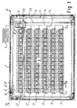
- Fig. 1 and 2 illustrate an automatic dispenser fitted as a dispenser of cigarette packets, which is intended to be placed near a cash desk in a self-service store or supermarket and in which a customer can select a desired packet of cigarettes of a given brand from among a large variety of different kinds and brands of cigarettes.
- the article to be selected in this example is a pack of cigarettes, it is to be understood that the automatic dispenser of the invention can be adapted for other goods as well.
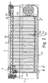
- the automatic dispenser comprises a housing 1, which is a box-like casing inside which the mechanisms of the automatic dispenser are assembled.
- the housing 1 comprises a vertical front wall 2 provided with a delivery orifice 3.
- the delivery orifice 3 is preferably placed in the upper part of the front wall 2.
- the delivery orifice 3 is preferably placed at a height such that it lies somewhat above the cash desk belt so that the pack of cigarettes can be dropped directly from the delivery orifice 3 onto the cash desk belt.
- a stock of goods 4 is provided inside the housing and it contains several sorts of goods, in this example many different brands of cigarettes in cigarette packets.
- a selector device 5 by means of which the user can select the desired item from among the various sorts of goods in stock, is placed within the user's reach.
- the selector device 5 may be e.g. a keyset panel in which each selecting key may be provided with pictures of different packets of cigarettes in the conventional manner.
- the stock of goods 4 is organized in such manner that the automatic dispenser comprises a number of horizontal shelves 7 1 ...7 6 placed one above the other, the example embodiment in Fig. 1 having six shelves. There is no limitation regarding the number of shelves placed above each other; instead, any suitable number of shelves may be used.
- Each shelf 7 1 ...7 6 is provided with compartments 8 1 ...8 16 disposed adjacently to and separated from each other, in which the packets of cigarettes can be placed in horizontal files 9 1 ...9 16 .
- Each compartment 8 1 ...8 16 comprises a front guard 10 for each file of goods.
- Fig. 1 shows the foremost packet in each file of cigarette packets, placed against the front guard 10. All front guards 10 are located in the same vertical plane.
- each compartment 8 1 ...8 16 is provided with a pusher P, which pushes the file of goods toward the front guard 10 so that the foremost item in the file leans against the front guard 10.
- each shelf comprises sixteen compartments 8 1 ..8 16 , so it is possible to load the automatic dispenser with 96 different sorts of goods.
- the number of compartments is not limited, but the dispenser may contain any suitable number of them.
- the pusher P in each compartment 8 1 ...8 16 comprises a slide element 55, which has been arranged to be movable along a groove 57 provided in the bottom 56 of the compartment. Connected to the slide element 55 is a back guard 58.
- a spring 59 acting between the slide element 55 and the bottom 56 exerts a force pushing the slide element 55 and the back guard 58 toward the front guard 10.
- the spring 59 may be e.g. a helical spring formed from spring steel band, producing a substantially constant spring force.
- One end of the spring is connected to the slide element 55 and the other end to the bottom 56 of the compartment 8 1 ...8 16 .
- the file of cigarette packets is placed between the back guard 58 and the front guard 10, the foremost packet in the file being thus pressed against the front guard 10.
- the automatic dispenser further comprises a conveying means 6 which picks up the selected item from the stock of goods and delivers it via the delivery orifice 3 so that the user can reach it.
- the conveying means 6 comprises a planar transfer mechanism 11 operating in a vertical plane on the front side of the shelves 7 1 ...7 6 , between the front guards 10 and the front wall 2.
- the delivery carriage 13 is connected to the planar transfer mechanism 11.
- the delivery carriage 13 can be moved by the planar transfer mechanism 11 in two dimensions in a vertical plane.
- the planar transfer mechanism 11 is able to move the delivery carriage 13 to a position opposite to the file 9 1 ... 9 16 of cigarette packets corresponding to the selected brand of cigarettes, move the foremost cigarette packet in the file over the front guard 10, receive the cigarette packet into the delivery carriage 13 and move the item to the delivery orifice 3, thus bringing it forth so that the user can reach it.
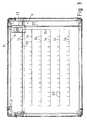
- Fig. 3 outlines the vertical and horizontal paths 14, 15 along which the planar transfer mechanism 11 has been arranged to move the delivery carriage 13.
- the vertical and horizontal transfer paths are because the delivery carriage 13 comprises a cam element 16 extending into the space on the side of the shelves 7 1 ...7 6 relative to the vertical plane formed by the front guards 10.
- the horizontal path 14 of the delivery carriage 13 is in the space between shelves 7 1 ...7 6 , while the vertical path 15 is in the space beside the shelves.
- the paths shown in Fig. 3 represent especially the paths of the cam element 16.
- the front guard 10 at the front end of each shelf 7 1 ...7 6 is provided with a slot 17 extending in the direction of the file of goods 9 1 ...9 16 .
- the delivery carriage 13 comprises a carriage frame 18 fitted in the space between the front guards 10 of the shelves and the front wall 2.
- the cam element 16 extends from the carriage frame 18 to a distance L relative to the front guard that is shorter than the dimension S of the item in the direction of the file.
- Fig. 3 outlines the short transfer paths 60 extending vertically from the horizontal transfer paths 14 between the shelves, representing the passage of the cam element 16 through the slot 17.
- the shelves 7 1 ...7 6 are fitted at a distance from each other such that they form horizontal free spaces between them to provide horizontal paths for the cam element 16.
- the shelves are so fitted inside the housing 1 that a vertical free space is formed in the housing on one side of the shelves to provide a vertical path 15 for the cam element 16.
- the delivery orifice 3 is located in the upper part of the front wall 2 in alignment with the vertical path 15 of the cam element 16.
- the delivery carriage 13 is shown in a position directly opposite to the delivery orifice 3.
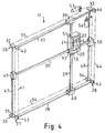
- Fig. 4 - 7 illustrate a preferred construction of the delivery carriage 13.
- the carriage frame 18 comprises a through aperture 19 which is limited in the downward direction by a sloping bottom 20 and in lateral directions by side walls 21, 22.
- the dimensions of the aperture 19 are larger than the outer dimensions of a cigarette packet.
- the front wall 2 of the housing 1 forms a lateral support for the article being conveyed in the aperture 19 of the carriage frame so that the article will only leave the aperture 19 after it has reached the delivery orifice 3.
- the use of the front wall 2 to keep the article in the aperture during the transfer serves the purpose of achieving a delivery carriage 13 that does not have to be provided with any sort of regulating element.
- the housing 1 comprises a door opening 23 disposed on the opposite side of the shelves 7 1 ...7 6 relative to the front wall 2.
- the door opening 23 can be closed with a so-called rulo-door.
- Each shelf 7 1 ...7 6 is supported on the housing 1 by horizontal slide runners 24. Supported by the slide runners 24, the shelves can be extracted through the door opening 23 so that they can be filled from above.
- Fig. 4 illustrates the structure of the planar transfer mechanism 11 used to move the delivery carriage 13.
- the planar transfer mechanism 11 comprises motor-driven belt drive mechanisms 25, 26, 27, 28.
- the vertical and horizontal guide bars 29, 30 are connected to the belt drive mechanisms so that they can be moved in horizontal and vertical directions, said vertical and horizontal guide bars 29, 30 simultaneously acting as guide bars for the delivery carriage 13 to allow the delivery carriage 13 to be moved in a vertical plane.
- a horizontal first belt drive mechanism 25 is disposed in the upper part of the housing 1.
- the first belt drive mechanism 25 comprises an endless first belt 31 and a first pair of belt pulleys 32, 33, over which the first belt is passed.
- a horizontal second belt drive mechanism 26 is disposed in the lower part of the housing 1 at a distance from the first belt drive mechanism.
- the second belt drive mechanism 26 comprises an endless second belt 34 and a second pair of belt pulleys 35, 36, over which the second belt 34 is passed.
- Horizontal first guide bars 37, 38 are placed in the vicinity of the first and second belt drive mechanisms.
- the vertical guide bar 29 is fastened by its ends to the first belt and similarly to the second belt and it extends in a vertical direction in front of the shelves. Connected to the vertical guide bar 29 are first slides 39, 40 near the ends. The first slides 39, 40 are guided by the first guide bars 37, 38.
- a vertical third belt drive mechanism 27 is provided on one side of the housing.
- the third belt drive mechanism 27 comprises an endless third belt 41 and a third pair of belt pulleys 42, 43, over which the third belt is passed.
- a vertical fourth belt drive mechanism 28 is provided on the other side of the housing at a distance from the third belt drive mechanism 27.
- the fourth belt drive mechanism 28 comprises an endless fourth belt 44 and a fourth pair of belt pulleys 45, 46, over which the fourth belt is passed.
- Vertical second guide bars 47, 48 are provided near the third and fourth belt drive mechanisms.
- a horizontal guide bar 30 is fastened by its ends to the third belt 41 and to the fourth belt 44 and extends horizontally in front of the shelves. Connected to the horizontal guide bar 30 are second slides 49, 50 near the ends. The second slides 49, 50 are guided by the second guide bars 47, 48.
- the delivery carriage 13 comprises a vertical first guide sleeve 51, which is guided by the vertical guide bar 29, and a horizontal second guide sleeve 52, which is guided by the horizontal guide bar 30.
- the belt pulleys 32, 33; 35, 36 of the first 25 and the second belt drive mechanism 26 are interconnected by vertical first shafts 47, 48 to synchronize the aforesaid belt drive mechanisms and to transmit traction.
- the first shafts 47, 48 function as aforesaid vertical second guide bars 47, 48 for the second slides 49, 50 placed at the ends of the horizontal guide bar 30 functioning as second guide bars 47, 48.
- the belt pulleys 42, 43; 45, 46 of the third 27 and fourth 28 belt drive mechanisms are interconnected by horizontal second shafts 37, 38 to synchronize the said belt drive mechanisms and to transmit traction.
- the second shafts 37, 38 have been arranged to function as said horizontal first guide bars 37, 38 for the first slides 39, 40 placed at the ends of the vertical guide bar 29.
- the planar transfer mechanism 11 is operated by a first motor 53 driving the first shaft 48 and second motor 54 driving the second shaft 37. No other motors or regulating elements are needed.
- the motors 53, 54 are e.g. servo motors, which can be controlled by a control device and by means of which the position of the delivery carriage 13 can be defined by the control device.
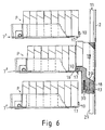
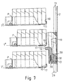
- Fig. 5 - 8 illustrate the delivery process.
- the delivery carriage 13 is in the stand-by position indicated in Fig. 3.
- the planar transfer mechanism 11 moves the delivery carriage 13 along the vertical and horizontal paths 14, 15 to a position below the end of the file corresponding to the selected sort of goods, i.e. in the example in Fig. 5 to a position opposite to the file of goods 9 4 on shelf 7 2 so that the cam element 16 lies directly below the slot 17.
- the delivery carriage 13 is raised so that the first cigarette packet in the file is lifted up and supported by the cam element 16.
- the next cigarette packet in the file, being pushed by the pusher P, is leaning against the forward surface of the cam element 16.
- the delivery carriage 13 is raised until the bottom of the cigarette packet passes over the front guard 10.
- the cam element 16 When the delivery carriage 13 is lowered again, the cam element 16 is disengaged from contact with the next cigarette packet in the file, and this packet is pressed by the pusher P against the front guard 10, thus becoming the foremost packet in the file. At the same time, it pushes the cigarette packet supported by the cam element 16 into the pocket consisting of the through aperture 19 in the delivery carriage 13. Its sloping bottom 20 guides the cigarette packet forward so that it comes to lean against the solid front wall 10 of the housing 1 as shown in Fig. 7.
- the planar transfer mechanism 11 moves the delivery carriage 13 to a position opposite to the delivery orifice 3, with the result that the cigarette packet in the aperture 19 of the delivery carriage 13 falls through the delivery orifice 13 so that it can be picked up by the user.
Description
- The present invention relates to an automatic dispenser as defined in the preamble of
claim 1. - An automatic dispenser is known from specification
WO 00/60553 - The document
JP-2000076535 claim 1. - In addition, the conveying means comprises a delivery carriage, which comprises a carriage frame fitted in the space between the front guards and the wall and which is connected to the planar transfer mechanism to allow the delivery carriage to be moved to a position directly opposite to the file of goods pertaining to the goods selected, the foremost item in the file to be moved across the front guard, the item to be received onto the delivery carriage and the item to be moved to the delivery orifice. To enable the item of goods to be moved onto the delivery carriage, the delivery carriage is provided with motor-driven fingers which lift the item from the end of the shelf onto supporting bars provided in the delivery carriage.
- A problem with this prior-art automatic dispenser is that, due to the movable fingers of the delivery carriage, the bearings of the various shafts, the toothed gears, motor and other components, the delivery carriage is expensive, complicated, heavy and susceptible to failure. The inertia of the mass of the delivery carriage involves certain limitations regarding minimization of the time required for retrieval of goods. Moreover, there are difficulties in transmitting the motor control signal to the movable delivery carriage. The larger the number of regulating elements in the automatic dispenser, the higher the demands imposed on the control system controlling the functions of the automatic dispenser because each regulating element has to be controlled separately.
- The object of the invention is to eliminate the above-mentioned disadvantages.
- A specific object of the invention is to disclose a compact automatic dispenser which, in comparison to its volume, contains a large stock and selection of goods. A further object of the invention is to disclose an automatic dispenser which is as simple as possible in structure, containing only a small number of regulating elements. Yet another object of the invention is to disclose an automatic dispenser in which case the time required for retrieval of goods is shorter than in the prior-art automatic dispenser.
-
Claim 1 discloses the present invention. Preferred embodiments are disclosed in claims 2-8. - The automatic dispenser of the invention is characterized by what is presented in
claim 1. - According to the invention, the delivery carriage comprises a cam element fixedly mounted relative to the carriage frame and fitted to extend from the carriage frame to a space on the side of the shelves relative to the vertical plane formed by the front guards of the shelves and to a distance smaller than the dimension of the item of goods in the direction of the file relative to the front guard, so that when the lifting carriage is moved vertically at the level of a shelf so that the cam element passes through the slot to lift the foremost item in the file of goods over the front guard and further so that it can be carried by the delivery carriage.
- The invention provides the advantage that the structure of the automatic dispenser is as simple as possible as it does not involve many regulating elements. The planar transfer mechanism can be operated by two motors. The delivery carriage requires no regulating element at all. The delivery carriage can be implemented as a very light structure, which means that the inertia of its mass imposes no load on the planar transfer mechanism and its power means. The light construction allows very fast changes of direction and movements of the delivery carriage and a short time of retrieval of goods.
- The automatic dispenser of the invention can be easily modified to suit different types of goods. It is required that the goods consist of relatively stiff material so that the package has a substantially regular shape. The automatic dispenser is especially suited for packages having the shape of a parallelopiped. Such packages include e.g. cigarette packets, candy boxes, medicine packages, etc. The automatic dispenser may be of a design that is operated without payment, such as e.g. a dispenser placed near the cash desk of a self-service store, or the automatic dispenser may be provided with a payment device so that the goods can be delivered from the dispenser against payment.
- In an embodiment of the automatic dispenser, the automatic dispenser comprises a pusher device arranged to push the file of goods against the front guard so that the foremost item in the file leans against the front guard.
- In an embodiment of the automatic dispenser, the planar transfer mechanism has been arranged to move the delivery carriage along horizontal and vertical paths.
- In an embodiment of the automatic dispenser, the horizontal path is in the space between shelves. The vertical path is in a space beside the shelves.
- In an embodiment of the automatic dispenser, the shelves are disposed at a distance from each other such that they form horizontal free spaces between them to provide horizontal paths for the cam element. The shelves are fitted in the space inside the housing so that at least one vertical free space is formed inside the housing to provide a vertical path for the cam element.
- In an embodiment of the automatic dispenser, the delivery orifice has been fitted in the front wall, preferably in its upper part, in alignment with the vertical path of the cam element.
- In an embodiment of the automatic dispenser, the carriage frame comprises a through aperture which in the downward direction is limited by a sloping bottom and in lateral directions by side walls, the dimensions of said aperture being larger than the outer dimensions of the goods. The front wall forms during conveyance a lateral support for the goods item, which lies in the aperture of the carriage frame so that it can only move away from the aperture after it has reached the delivery orifice.
- In an embodiment of the automatic dispenser, the housing of the apparatus comprises a door opening disposed on the opposite side of the shelves relative to the front wall. Each shelf is supported by horizontal slide runners permitting the shelf to be pulled out through the door opening so that it can be loaded with goods from above.
- In an embodiment of the automatic dispenser, the planar transfer mechanism comprises motor-driven belt drive mechanisms, and vertical and horizontal guide bars connected to the belt drive mechanisms so that they can be moved horizontally and vertically, said vertical and horizontal guide bars simultaneously acting as guide bars of the delivery carriage to allow the latter to be moved in a vertical plane.
- In an embodiment of the automatic dispenser, the planar transfer mechanism comprises: a horizontal first belt drive mechanism, which is located in the upper part of the housing and comprises an endless first belt and a first pair of belt pulleys, said first belt being passed over said first pair of belt pulleys; a horizontal second belt drive mechanism, which is disposed in the lower part of the housing at a distance from the first belt drive mechanism and comprises an endless second belt and a second pair of belt pulleys, said second belt being passed over said second pair of belt pulleys; horizontal first guide bars in the vicinity of the first and second belt drive mechanisms; a vertical guide bar fastened by its ends to the first belt and to the second belt and extending vertically in front of the shelves, with first slides connected to said vertical guide bar near its ends, said first slides being guided by said first guide bars; a vertical third belt drive mechanism located on one side of the housing of the apparatus and comprising an endless third belt and a third pair of belt pulleys, said third belt being passed over said third pair of belt pulleys; a vertical fourth belt drive mechanism disposed on the other side of the housing at a distance from the third belt drive mechanism and comprising an endless fourth belt and a fourth pair of belt pulleys, said fourth belt being passed over said fourth pair of belt pulleys; vertical second guide bars in the vicinity of the third and fourth belt drive mechanisms; a horizontal guide bar fastened by its ends to the third belt and to the fourth belt and extending horizontally in front of the shelves, with second slides connected to said horizontal guide bar near its ends, said second slides being guided by said second guide bars. The delivery carriage comprises a vertical first guide sleeve, which is guided by the vertical guide bar, and a horizontal second guide sleeve, which is guided by the horizontal guide bar.
- In an embodiment of the automatic dispenser, the belt pulleys of the first and second belt drive mechanisms are interconnected by vertical first shafts to synchronize said belt drive mechanisms and to transmit traction. The planar transfer mechanism comprises a first motor for driving a first shaft. The first shafts are designed to act as said vertical second guide bars.
- In an embodiment of the automatic dispenser, the belt pulleys of the third and fourth belt drive mechanisms are interconnected by horizontal second shafts to synchronize said belt drive mechanisms and to transmit traction. The planar transfer mechanism comprises a second motor for driving a second shaft. The second shafts are designed to act as said horizontal first guide bars.
- In the following, the invention will be described in detail by the aid of a few examples of its embodiments with reference to the attached drawings, wherein
- Fig. 1 presents a diagrammatic front view of an embodiment of the automatic dispenser of the invention without a front wall,
- Fig. 2 presents a section II-II through the automatic dispenser of Fig. 1,
- Fig. 3 presents a front view of the conveying means of the automatic dispenser in Fig. 1, also showing the horizontal and vertical paths of the delivery carriage,
- Fig. 4 presents a diagrammatic axonometric view of the conveying means of the automatic dispenser in Fig. 1,
- Fig. 5 - 7 present diagrammatic side views of a part of the automatic dispenser in Fig. 1 with the conveying means performing a delivery operation, showing different stages of the operation, the delivery carriage being vertically sectioned, and
- Fig. 8 diagrammatic and vertically sectioned side view of the delivery carriage at the final stage of the delivery operation when the carriage is in a position directly opposite to the delivery orifice.
- Fig. 1 and 2 illustrate an automatic dispenser fitted as a dispenser of cigarette packets, which is intended to be placed near a cash desk in a self-service store or supermarket and in which a customer can select a desired packet of cigarettes of a given brand from among a large variety of different kinds and brands of cigarettes. Although the article to be selected in this example is a pack of cigarettes, it is to be understood that the automatic dispenser of the invention can be adapted for other goods as well.
- The automatic dispenser comprises a
housing 1, which is a box-like casing inside which the mechanisms of the automatic dispenser are assembled. As shown in Fig. 2, thehousing 1 comprises a verticalfront wall 2 provided with adelivery orifice 3. As thehousing 1 is mounted on the floor, thedelivery orifice 3 is preferably placed in the upper part of thefront wall 2. Thedelivery orifice 3 is preferably placed at a height such that it lies somewhat above the cash desk belt so that the pack of cigarettes can be dropped directly from thedelivery orifice 3 onto the cash desk belt. - A stock of goods 4 is provided inside the housing and it contains several sorts of goods, in this example many different brands of cigarettes in cigarette packets. A
selector device 5, by means of which the user can select the desired item from among the various sorts of goods in stock, is placed within the user's reach. Theselector device 5 may be e.g. a keyset panel in which each selecting key may be provided with pictures of different packets of cigarettes in the conventional manner. The stock of goods 4 is organized in such manner that the automatic dispenser comprises a number of horizontal shelves 71...76 placed one above the other, the example embodiment in Fig. 1 having six shelves. There is no limitation regarding the number of shelves placed above each other; instead, any suitable number of shelves may be used. - Each shelf 71...76 is provided with
compartments 81...816 disposed adjacently to and separated from each other, in which the packets of cigarettes can be placed in horizontal files 91...916. Eachcompartment 81...816 comprises afront guard 10 for each file of goods. Fig. 1 shows the foremost packet in each file of cigarette packets, placed against thefront guard 10. Allfront guards 10 are located in the same vertical plane. As shown in Fig. 2 and Fig. 5 - 7, eachcompartment 81...816 is provided with a pusher P, which pushes the file of goods toward thefront guard 10 so that the foremost item in the file leans against thefront guard 10. In the example embodiment presented in Fig. 1, each shelf comprises sixteencompartments 81..816, so it is possible to load the automatic dispenser with 96 different sorts of goods. The number of compartments is not limited, but the dispenser may contain any suitable number of them. - As can be seen from Fig. 2 and 5 - 7, the pusher P in each
compartment 81...816 comprises aslide element 55, which has been arranged to be movable along agroove 57 provided in the bottom 56 of the compartment. Connected to theslide element 55 is aback guard 58. Aspring 59 acting between theslide element 55 and the bottom 56 exerts a force pushing theslide element 55 and theback guard 58 toward thefront guard 10. Thespring 59 may be e.g. a helical spring formed from spring steel band, producing a substantially constant spring force. One end of the spring is connected to theslide element 55 and the other end to the bottom 56 of thecompartment 81...816. The file of cigarette packets is placed between theback guard 58 and thefront guard 10, the foremost packet in the file being thus pressed against thefront guard 10. - The automatic dispenser further comprises a conveying
means 6 which picks up the selected item from the stock of goods and delivers it via thedelivery orifice 3 so that the user can reach it. - The conveying means 6 comprises a
planar transfer mechanism 11 operating in a vertical plane on the front side of the shelves 71...76, between thefront guards 10 and thefront wall 2. Thedelivery carriage 13 is connected to theplanar transfer mechanism 11. Thedelivery carriage 13 can be moved by theplanar transfer mechanism 11 in two dimensions in a vertical plane. Thus, theplanar transfer mechanism 11 is able to move thedelivery carriage 13 to a position opposite to the file 91... 916 of cigarette packets corresponding to the selected brand of cigarettes, move the foremost cigarette packet in the file over thefront guard 10, receive the cigarette packet into thedelivery carriage 13 and move the item to thedelivery orifice 3, thus bringing it forth so that the user can reach it. - Fig. 3 outlines the vertical and
horizontal paths planar transfer mechanism 11 has been arranged to move thedelivery carriage 13. The vertical and horizontal transfer paths are because thedelivery carriage 13 comprises acam element 16 extending into the space on the side of the shelves 71...76relative to the vertical plane formed by the front guards 10. Thehorizontal path 14 of thedelivery carriage 13 is in the space between shelves 71...76, while thevertical path 15 is in the space beside the shelves. The paths shown in Fig. 3 represent especially the paths of thecam element 16. - As shown in Fig. 2 and Fig. 5 - 7, the
front guard 10 at the front end of each shelf 71...76 is provided with aslot 17 extending in the direction of the file of goods 91...916. Thedelivery carriage 13 comprises acarriage frame 18 fitted in the space between thefront guards 10 of the shelves and thefront wall 2. As shown in Fig. 5, thecam element 16 extends from thecarriage frame 18 to a distance L relative to the front guard that is shorter than the dimension S of the item in the direction of the file. Thus, when the liftingcarriage 16 is moved vertically in alignment with theslot 17, thecam element 16 can move through theslot 17 to lift the foremost item in the file of goods over thefront guard 10 so that the item can enter thedelivery carriage 13 and be conveyed by it as explained in connection with Fig. 5 - 7. Fig. 3 outlines theshort transfer paths 60 extending vertically from thehorizontal transfer paths 14 between the shelves, representing the passage of thecam element 16 through theslot 17. - The shelves 71...76 are fitted at a distance from each other such that they form horizontal free spaces between them to provide horizontal paths for the
cam element 16. In addition, the shelves are so fitted inside thehousing 1 that a vertical free space is formed in the housing on one side of the shelves to provide avertical path 15 for thecam element 16. - The
delivery orifice 3 is located in the upper part of thefront wall 2 in alignment with thevertical path 15 of thecam element 16. In Fig. 1 and 3, thedelivery carriage 13 is shown in a position directly opposite to thedelivery orifice 3. - Fig. 4 - 7 illustrate a preferred construction of the
delivery carriage 13. Thecarriage frame 18 comprises a throughaperture 19 which is limited in the downward direction by a slopingbottom 20 and in lateral directions byside walls 21, 22. The dimensions of theaperture 19 are larger than the outer dimensions of a cigarette packet. Thefront wall 2 of thehousing 1 forms a lateral support for the article being conveyed in theaperture 19 of the carriage frame so that the article will only leave theaperture 19 after it has reached thedelivery orifice 3. The use of thefront wall 2 to keep the article in the aperture during the transfer serves the purpose of achieving adelivery carriage 13 that does not have to be provided with any sort of regulating element. - Further referring to Fig. 2, the
housing 1 comprises adoor opening 23 disposed on the opposite side of the shelves 71...76 relative to thefront wall 2. Thedoor opening 23 can be closed with a so-called rulo-door. Each shelf 71...76 is supported on thehousing 1 byhorizontal slide runners 24. Supported by theslide runners 24, the shelves can be extracted through the door opening 23 so that they can be filled from above. - Fig. 4 illustrates the structure of the
planar transfer mechanism 11 used to move thedelivery carriage 13. Theplanar transfer mechanism 11 comprises motor-drivenbelt drive mechanisms delivery carriage 13 to allow thedelivery carriage 13 to be moved in a vertical plane. - A horizontal first
belt drive mechanism 25 is disposed in the upper part of thehousing 1. The firstbelt drive mechanism 25 comprises an endlessfirst belt 31 and a first pair of belt pulleys 32, 33, over which the first belt is passed. - A horizontal second
belt drive mechanism 26 is disposed in the lower part of thehousing 1 at a distance from the first belt drive mechanism. The secondbelt drive mechanism 26 comprises an endlesssecond belt 34 and a second pair of belt pulleys 35, 36, over which thesecond belt 34 is passed. - Horizontal first guide bars 37, 38 are placed in the vicinity of the first and second belt drive mechanisms.
- The
vertical guide bar 29 is fastened by its ends to the first belt and similarly to the second belt and it extends in a vertical direction in front of the shelves. Connected to thevertical guide bar 29 arefirst slides - A vertical third
belt drive mechanism 27 is provided on one side of the housing. The thirdbelt drive mechanism 27 comprises an endless third belt 41 and a third pair of belt pulleys 42, 43, over which the third belt is passed. - A vertical fourth
belt drive mechanism 28 is provided on the other side of the housing at a distance from the thirdbelt drive mechanism 27. The fourthbelt drive mechanism 28 comprises an endlessfourth belt 44 and a fourth pair of belt pulleys 45, 46, over which the fourth belt is passed. - Vertical second guide bars 47, 48 are provided near the third and fourth belt drive mechanisms.
- A
horizontal guide bar 30 is fastened by its ends to the third belt 41 and to thefourth belt 44 and extends horizontally in front of the shelves. Connected to thehorizontal guide bar 30 aresecond slides - The
delivery carriage 13 comprises a verticalfirst guide sleeve 51, which is guided by thevertical guide bar 29, and a horizontalsecond guide sleeve 52, which is guided by thehorizontal guide bar 30. - The belt pulleys 32, 33; 35, 36 of the first 25 and the second
belt drive mechanism 26 are interconnected by verticalfirst shafts first shafts horizontal guide bar 30 functioning as second guide bars 47, 48. - The belt pulleys 42, 43; 45, 46 of the third 27 and fourth 28 belt drive mechanisms are interconnected by horizontal
second shafts second shafts vertical guide bar 29. - The
planar transfer mechanism 11 is operated by afirst motor 53 driving thefirst shaft 48 andsecond motor 54 driving thesecond shaft 37. No other motors or regulating elements are needed. Themotors delivery carriage 13 can be defined by the control device. - Fig. 5 - 8 illustrate the delivery process. At the beginning of the action, the
delivery carriage 13 is in the stand-by position indicated in Fig. 3. Once the customer has made a selection via the selectingdevice 5, theplanar transfer mechanism 11 moves thedelivery carriage 13 along the vertical andhorizontal paths cam element 16 lies directly below theslot 17. - Next, as shown in Fig. 6, the
delivery carriage 13 is raised so that the first cigarette packet in the file is lifted up and supported by thecam element 16. The next cigarette packet in the file, being pushed by the pusher P, is leaning against the forward surface of thecam element 16. Thedelivery carriage 13 is raised until the bottom of the cigarette packet passes over thefront guard 10. - When the
delivery carriage 13 is lowered again, thecam element 16 is disengaged from contact with the next cigarette packet in the file, and this packet is pressed by the pusher P against thefront guard 10, thus becoming the foremost packet in the file. At the same time, it pushes the cigarette packet supported by thecam element 16 into the pocket consisting of the throughaperture 19 in thedelivery carriage 13. Its sloping bottom 20 guides the cigarette packet forward so that it comes to lean against the solidfront wall 10 of thehousing 1 as shown in Fig. 7. - Referring to Fig. 8, the
planar transfer mechanism 11 moves thedelivery carriage 13 to a position opposite to thedelivery orifice 3, with the result that the cigarette packet in theaperture 19 of thedelivery carriage 13 falls through thedelivery orifice 13 so that it can be picked up by the user.
Claims (8)
- Automatic dispenser, comprising- a housing (1) with a wall (2) provided with a delivery orifice (3) for the delivery of goods;- a stock of goods (4), which is placed inside the housing and may contain several sorts of goods;- a selecting device (5), by means of which the user can select a desired item from among the various sorts of goods available in the stock of goods;- a number of shelves (71... 76) placed one above the other, each shelf comprising a number of adjacent compartments (81...816) where the goods can be placed in files of goods (91...916) to form the said stock of goods (4), each compartment comprising a front guard (10) for each file of goods, all front guards being located substantially in the same vertical plane, the front end of the shelf (71... 76) and the front guard (10) being provided with a slot (17) extending in the direction of the file of goods (91... 916) ; and- a conveying means (6) for moving the selected item from the stock of goods through the delivery orifice and bringing it within the user's reach, said conveying means (6) comprisingsaid delivery carriage (13) being connected to said planar transfer mechanism (11) which is disposed to move the delivery carriage (13) along horizontal and vertical paths (14, 15) to a position directly opposite to the file of goods (91...916) pertaining to the item selected, to move the delivery carriage (13) vertically so that the cam element (16) passes through said slot (17) and lifts the foremost item in the file of goods over the front guard (10) to the delivery carriage (13), and to move the delivery carriage (13) to the delivery orifice (3) for dispensing of the item, characterized in that the cam element (16) is fixed to the carriage frame (18) and thereby fixedly extends from the carriage frame (18) into the space on the side of the shelves (71...76) relative to the vertical plane formed by the front guards (10) of the shelves and to a distance (L) smaller than the dimension (S) of the item of goods in the direction of the file relative to the front guard (10); that the shelves (71...76) are disposed at a distance from each other to form horizontal free spaces between the shelves in order to provide horizontal paths (14) for the movement of the cam element (16); and that the shelves are fitted in the space inside the housing (1) so that at least one vertical free space is formed inside the housing to provide a vertical path (15) for the movement of the cam element (16).-- a planar transfer mechanism (11) arranged to operate in a vertical plane on the front side of the shelves (71...76), between the front guards (10) and the wall (2), and-- a delivery carriage (13), comprising a carriage frame (18) fitted in the space between the front guards (10) and the wall (2), and a cam element (16) connected to the carriage frame,
- Automatic dispenser as defined in claim 1, characterized in that the automatic dispenser comprises a pusher device (P) arranged to push the file of goods (91...916) against the front guard (10) so that the foremost item in the file leans against the front guard.
- Automatic dispenser as defined in claim 1 or 2, characterized in that the delivery orifice (3) has been fitted in the wall (2), preferably in its upper part, in alignment with the vertical path (15) of the cam element (16).
- Automatic dispenser as defined in any one of claims 1 - 3, characterized in that the carriage frame (18) comprises a through aperture (19) which in the downward direction is limited by a sloping bottom (20) and in lateral directions by side walls (21, 22) and whose dimensions are larger than the outer dimensions of the item of goods; and that the wall (2) forms during conveyance a lateral support for the item, which lies in the aperture (19) of the carriage frame so that it can only leave the aperture (19) after it has reached the delivery orifice (3).
- Automatic dispenser as defined in any one of claims 1 - 4, characterized in that the housing (1) comprises a door opening (23) disposed on the opposite side of the shelves (71...76) relative to the wall (2); and that each shelf is supported by horizontal slide runners (24) on which the shelf can be pulled out through the door opening to allow the shelf to be loaded with goods from above.
- Automatic dispenser as defined in any one of claims 1 - 5, characterized in that the planar transfer mechanism (11) comprises motor-driven, belt drive mechanisms(25, 26, 27, 28) and vertical and horizontal guide bars (29, 30) connected to the belt drive mechanisms so that they can be moved horizontally and vertically, said vertical and horizontal guide bars (29, 30) simultaneously acting as guide bars for the delivery carriage (13) to allow the delivery carriage (13) to be moved in a vertical plane.
- Automatic dispenser as defined in claim 6, characterized in that the planar transfer mechanism (11) comprises- a horizontal first belt drive mechanism (25), which is located in the upper part of the housing (1) and comprises an endless first belt (31) and a first pair of belt pulleys (32, 32), said first belt being passed over said first pair of belt pulleys,- a horizontal second belt drive mechanism (26), which is disposed in the lower part of the housing at a distance from the first belt drive mechanism and comprises an endless second belt (34) and a second pair of belt pulleys (35, 36), said second belt being passed over said second pair of belt pulleys;- horizontal first guide bars (37, 38) in the vicinity of the first and second belt drive mechanisms,- a vertical guide bar (29) fastened by its ends to the first belt and to the second belt and extending vertically in front of the shelves, with first slides (39, 40) connected to said vertical guide bar near its ends, said first slides being guided by said first guide bars (37, 38),- a vertical third belt drive mechanism (27) located on one side of the housing of the apparatus and comprising an endless third belt (41) and a third pair of belt pulleys (42, 43), said third belt being passed over said third pair of belt pulleys,- a vertical fourth belt drive mechanism (28) disposed on the other side of the housing at a distance from the third belt drive mechanism and comprising an endless fourth belt (44) and a fourth pair of belt pulleys (45, 46), said fourth belt being passed over said fourth pair of belt pulleys,- vertical second guide bars (47, 48) in the vicinity of the third and fourth belt drive mechanisms,- a horizontal guide bar (30) fastened by its ends to the third belt and to the fourth belt and extending horizontally in front of the shelves, with second slides (49, 50) connected to said horizontal guide bar near its ends, said second slides being guided by said second guide bars (47, 48),and that the delivery carriage (13) comprises a vertical first guide sleeve (51), which is guided by the vertical guide bar (29), and a horizontal second guide sleeve (52), which is guided by the horizontal guide bar (30).
- Automatic dispenser as defined in claim 7, characterized in that the belt pulleys (32, 33; 35, 36) of the first (25) and second (26) belt drive mechanisms are interconnected by vertical first shafts (47, 48) to synchronize said belt drive mechanisms and to transmit traction; that the planar transfer mechanism (11) comprises a first motor (53) for driving a first shaft (47 or 48); and that the first shafts (47, 48) are designed to act as said vertical second guide bars (47, 48); and/or that
the belt pulleys (42, 43; 45, 46) of the third (27) and fourth (28) belt drive mechanisms are interconnected by horizontal second shafts (37, 38) to synchronize said belt drive mechanisms and to transmit traction; that the planar transfer mechanism (11) comprises a second motor (54) for driving a second shaft (37 or 38); that the second shafts (37, 38) are designed to act as said horizontal first guide bars (37, 38).
Applications Claiming Priority (3)
| Application Number | Priority Date | Filing Date | Title |
|---|---|---|---|
| FI20002371 | 2000-10-27 | ||
| FI20002371A FI20002371A0 (en) | 2000-10-27 | 2000-10-27 | Automatic |
| PCT/FI2001/000912 WO2002035484A1 (en) | 2000-10-27 | 2001-10-19 | Automatic dispenser |
Publications (2)
| Publication Number | Publication Date |
|---|---|
| EP1337983A1 EP1337983A1 (en) | 2003-08-27 |
| EP1337983B1 true EP1337983B1 (en) | 2007-11-21 |
Family
ID=8559384
Family Applications (1)
| Application Number | Title | Priority Date | Filing Date |
|---|---|---|---|
| EP01980560A Expired - Lifetime EP1337983B1 (en) | 2000-10-27 | 2001-10-19 | Automatic dispenser |
Country Status (5)
| Country | Link |
|---|---|
| EP (1) | EP1337983B1 (en) |
| AU (1) | AU2002212374A1 (en) |
| DE (1) | DE60131559D1 (en) |
| FI (1) | FI20002371A0 (en) |
| WO (1) | WO2002035484A1 (en) |
Cited By (2)
| Publication number | Priority date | Publication date | Assignee | Title |
|---|---|---|---|---|
| CN106081460A (en) * | 2016-08-11 | 2016-11-09 | 苏州欧伟力自动化设备有限公司 | Charging tray storage rack and charging tray store method |
| CN106241168A (en) * | 2016-09-13 | 2016-12-21 | 国网辽宁省电力有限公司电力科学研究院 | A kind of fluent shelf intelligent management apapratus and method |
Families Citing this family (9)
| Publication number | Priority date | Publication date | Assignee | Title |
|---|---|---|---|---|
| WO2007012073A2 (en) * | 2005-07-20 | 2007-01-25 | Coin Acceptors | Method of retrofitting a vending machine |
| EP2390849B1 (en) * | 2007-05-16 | 2014-07-30 | Sanden Corporation | Commodity carrying out device |
| EP2012281B1 (en) * | 2007-05-21 | 2014-11-19 | Sanden Corporation | Commodity carrying out device |
| ES2388097B1 (en) * | 2010-03-22 | 2013-08-23 | Azkoyen, S.A. | CONTAINER AND EXTRACTOR MECHANISM OF PRODUCTS FOR EXPENDING MACHINES. |
| SE1150103A1 (en) * | 2011-02-10 | 2012-08-11 | Frepart Ab | storage Systems |
| WO2012124192A1 (en) * | 2011-03-16 | 2012-09-20 | 富士電機リテイルシステムズ株式会社 | Vending machine |
| EP3332672A1 (en) * | 2016-12-12 | 2018-06-13 | smark - Philipp Hoening & Maximilian Ittermann GbR | Mobile magazine |
| CN108009614A (en) * | 2018-01-09 | 2018-05-08 | 广州大学 | A kind of Automatic object distribution device |
| CN112773106B (en) * | 2021-02-27 | 2022-07-19 | 东港瑞云数据技术有限公司 | Intelligent file access system and file access method |
Family Cites Families (5)
| Publication number | Priority date | Publication date | Assignee | Title |
|---|---|---|---|---|
| US4134520A (en) * | 1977-01-24 | 1979-01-16 | Rod Pierce & Associates | Article dispensing machine with spring-driven carriages for advancing articles to be dispensed |
| CA1260117A (en) * | 1985-02-14 | 1989-09-26 | Nelson Vending Technology Limited | Automatic vending machine |
| JP3159648B2 (en) * | 1996-05-17 | 2001-04-23 | 松下冷機株式会社 | Vending machine product transfer equipment |
| JP2000076535A (en) * | 1998-08-27 | 2000-03-14 | Toshiba Corp | Automatic vending machine |
| CN1161718C (en) * | 1999-04-02 | 2004-08-11 | 可口可乐公司 | Dispensing apparatus and method of using same |
-
2000
- 2000-10-27 FI FI20002371A patent/FI20002371A0/en unknown
-
2001
- 2001-10-19 DE DE60131559T patent/DE60131559D1/en not_active Expired - Lifetime
- 2001-10-19 EP EP01980560A patent/EP1337983B1/en not_active Expired - Lifetime
- 2001-10-19 WO PCT/FI2001/000912 patent/WO2002035484A1/en active IP Right Grant
- 2001-10-19 AU AU2002212374A patent/AU2002212374A1/en not_active Abandoned
Cited By (4)
| Publication number | Priority date | Publication date | Assignee | Title |
|---|---|---|---|---|
| CN106081460A (en) * | 2016-08-11 | 2016-11-09 | 苏州欧伟力自动化设备有限公司 | Charging tray storage rack and charging tray store method |
| CN106081460B (en) * | 2016-08-11 | 2018-07-10 | 苏州欧伟力自动化设备有限公司 | Charging tray stores method |
| CN106241168A (en) * | 2016-09-13 | 2016-12-21 | 国网辽宁省电力有限公司电力科学研究院 | A kind of fluent shelf intelligent management apapratus and method |
| CN106241168B (en) * | 2016-09-13 | 2019-03-29 | 国网辽宁省电力有限公司电力科学研究院 | A kind of fluent shelf intelligent management apapratus and method |
Also Published As
| Publication number | Publication date |
|---|---|
| WO2002035484A1 (en) | 2002-05-02 |
| AU2002212374A1 (en) | 2002-05-06 |
| FI20002371A0 (en) | 2000-10-27 |
| EP1337983A1 (en) | 2003-08-27 |
| DE60131559D1 (en) | 2008-01-03 |
Similar Documents
| Publication | Publication Date | Title |
|---|---|---|
| EP1166241B1 (en) | Vending machine which minimises agitation of goods | |
| US6962267B2 (en) | Automated shopping system | |
| US6286715B1 (en) | Transparent front vending machine | |
| US3348732A (en) | Article dispensing device | |
| EP1337983B1 (en) | Automatic dispenser | |
| KR100264373B1 (en) | Vending machine for packaged commidties | |
| US3991907A (en) | Solid merchandise dispensing system for mechanical or electrical control | |
| US6729499B2 (en) | System for conveying a selected product to a collection compartment in automatic vending machines | |
| JP2957639B2 (en) | Vending machine product transfer equipment | |
| JP2557504B2 (en) | vending machine | |
| JP7252848B2 (en) | Vending machines, product storage racks and product unloading devices | |
| KR0130748B1 (en) | A rticle receipt device for automatic vending machine | |
| JP2815550B2 (en) | Transfer device | |
| JP5272402B2 (en) | vending machine | |
| JP2005128684A (en) | Automatic vending machine | |
| JPH11175838A (en) | Automatic vending machine | |
| JP2005128683A (en) | Vending machine | |
| JP2009157718A (en) | Vending machine | |
| JP2906359B2 (en) | Direct loading vending machine | |
| CN110942554A (en) | Automatic vending equipment | |
| KR19990012026U (en) | Rack Drive Units in Vending Machine | |
| JP2009157717A (en) | Vending machine | |
| JP2009157716A (en) | Vending machine | |
| JPH0887672A (en) | Article extracting device and automatic vending machine using the same | |
| JP2007172355A (en) | Article conveyer for automatic vending machine |
Legal Events
| Date | Code | Title | Description |
|---|---|---|---|
| PUAI | Public reference made under article 153(3) epc to a published international application that has entered the european phase |
Free format text: ORIGINAL CODE: 0009012 |
|
| 17P | Request for examination filed |
Effective date: 20030509 |
|
| AK | Designated contracting states |
Designated state(s): AT BE CH CY DE DK ES FI FR GB GR IE IT LI LU MC NL PT SE TR |
|
| AX | Request for extension of the european patent |
Extension state: AL LT LV MK RO SI |
|
| 17Q | First examination report despatched |
Effective date: 20061102 |
|
| GRAP | Despatch of communication of intention to grant a patent |
Free format text: ORIGINAL CODE: EPIDOSNIGR1 |
|
| GRAS | Grant fee paid |
Free format text: ORIGINAL CODE: EPIDOSNIGR3 |
|
| GRAA | (expected) grant |
Free format text: ORIGINAL CODE: 0009210 |
|
| AK | Designated contracting states |
Kind code of ref document: B1 Designated state(s): AT BE CH CY DE DK ES FI FR GB GR IE IT LI LU MC NL PT SE TR |
|
| REG | Reference to a national code |
Ref country code: GB Ref legal event code: FG4D |
|
| REG | Reference to a national code |
Ref country code: IE Ref legal event code: FG4D |
|
| REG | Reference to a national code |
Ref country code: CH Ref legal event code: EP |
|
| REF | Corresponds to: |
Ref document number: 60131559 Country of ref document: DE Date of ref document: 20080103 Kind code of ref document: P |
|
| PG25 | Lapsed in a contracting state [announced via postgrant information from national office to epo] |
Ref country code: SE Free format text: LAPSE BECAUSE OF FAILURE TO SUBMIT A TRANSLATION OF THE DESCRIPTION OR TO PAY THE FEE WITHIN THE PRESCRIBED TIME-LIMIT Effective date: 20080221 Ref country code: CH Free format text: LAPSE BECAUSE OF FAILURE TO SUBMIT A TRANSLATION OF THE DESCRIPTION OR TO PAY THE FEE WITHIN THE PRESCRIBED TIME-LIMIT Effective date: 20071121 Ref country code: LI Free format text: LAPSE BECAUSE OF FAILURE TO SUBMIT A TRANSLATION OF THE DESCRIPTION OR TO PAY THE FEE WITHIN THE PRESCRIBED TIME-LIMIT Effective date: 20071121 Ref country code: ES Free format text: LAPSE BECAUSE OF FAILURE TO SUBMIT A TRANSLATION OF THE DESCRIPTION OR TO PAY THE FEE WITHIN THE PRESCRIBED TIME-LIMIT Effective date: 20080304 Ref country code: NL Free format text: LAPSE BECAUSE OF FAILURE TO SUBMIT A TRANSLATION OF THE DESCRIPTION OR TO PAY THE FEE WITHIN THE PRESCRIBED TIME-LIMIT Effective date: 20071121 |
|
| NLV1 | Nl: lapsed or annulled due to failure to fulfill the requirements of art. 29p and 29m of the patents act | ||
| PG25 | Lapsed in a contracting state [announced via postgrant information from national office to epo] |
Ref country code: FI Free format text: LAPSE BECAUSE OF FAILURE TO SUBMIT A TRANSLATION OF THE DESCRIPTION OR TO PAY THE FEE WITHIN THE PRESCRIBED TIME-LIMIT Effective date: 20071121 |
|
| REG | Reference to a national code |
Ref country code: CH Ref legal event code: PL |
|
| PG25 | Lapsed in a contracting state [announced via postgrant information from national office to epo] |
Ref country code: AT Free format text: LAPSE BECAUSE OF FAILURE TO SUBMIT A TRANSLATION OF THE DESCRIPTION OR TO PAY THE FEE WITHIN THE PRESCRIBED TIME-LIMIT Effective date: 20071121 |
|
| PG25 | Lapsed in a contracting state [announced via postgrant information from national office to epo] |
Ref country code: DK Free format text: LAPSE BECAUSE OF FAILURE TO SUBMIT A TRANSLATION OF THE DESCRIPTION OR TO PAY THE FEE WITHIN THE PRESCRIBED TIME-LIMIT Effective date: 20071121 |
|
| PG25 | Lapsed in a contracting state [announced via postgrant information from national office to epo] |
Ref country code: BE Free format text: LAPSE BECAUSE OF FAILURE TO SUBMIT A TRANSLATION OF THE DESCRIPTION OR TO PAY THE FEE WITHIN THE PRESCRIBED TIME-LIMIT Effective date: 20071121 |
|
| PLBE | No opposition filed within time limit |
Free format text: ORIGINAL CODE: 0009261 |
|
| STAA | Information on the status of an ep patent application or granted ep patent |
Free format text: STATUS: NO OPPOSITION FILED WITHIN TIME LIMIT |
|
| PG25 | Lapsed in a contracting state [announced via postgrant information from national office to epo] |
Ref country code: PT Free format text: LAPSE BECAUSE OF FAILURE TO SUBMIT A TRANSLATION OF THE DESCRIPTION OR TO PAY THE FEE WITHIN THE PRESCRIBED TIME-LIMIT Effective date: 20080421 |
|
| 26N | No opposition filed |
Effective date: 20080822 |
|
| PG25 | Lapsed in a contracting state [announced via postgrant information from national office to epo] |
Ref country code: DE Free format text: LAPSE BECAUSE OF FAILURE TO SUBMIT A TRANSLATION OF THE DESCRIPTION OR TO PAY THE FEE WITHIN THE PRESCRIBED TIME-LIMIT Effective date: 20080222 Ref country code: FR Free format text: LAPSE BECAUSE OF FAILURE TO SUBMIT A TRANSLATION OF THE DESCRIPTION OR TO PAY THE FEE WITHIN THE PRESCRIBED TIME-LIMIT Effective date: 20080905 |
|
| PG25 | Lapsed in a contracting state [announced via postgrant information from national office to epo] |
Ref country code: GR Free format text: LAPSE BECAUSE OF FAILURE TO SUBMIT A TRANSLATION OF THE DESCRIPTION OR TO PAY THE FEE WITHIN THE PRESCRIBED TIME-LIMIT Effective date: 20080222 |
|
| PG25 | Lapsed in a contracting state [announced via postgrant information from national office to epo] |
Ref country code: MC Free format text: LAPSE BECAUSE OF NON-PAYMENT OF DUE FEES Effective date: 20081031 |
|
| GBPC | Gb: european patent ceased through non-payment of renewal fee |
Effective date: 20081019 |
|
| PG25 | Lapsed in a contracting state [announced via postgrant information from national office to epo] |
Ref country code: CY Free format text: LAPSE BECAUSE OF FAILURE TO SUBMIT A TRANSLATION OF THE DESCRIPTION OR TO PAY THE FEE WITHIN THE PRESCRIBED TIME-LIMIT Effective date: 20071121 |
|
| PG25 | Lapsed in a contracting state [announced via postgrant information from national office to epo] |
Ref country code: IE Free format text: LAPSE BECAUSE OF NON-PAYMENT OF DUE FEES Effective date: 20081020 |
|
| PG25 | Lapsed in a contracting state [announced via postgrant information from national office to epo] |
Ref country code: GB Free format text: LAPSE BECAUSE OF NON-PAYMENT OF DUE FEES Effective date: 20081019 |
|
| PG25 | Lapsed in a contracting state [announced via postgrant information from national office to epo] |
Ref country code: LU Free format text: LAPSE BECAUSE OF NON-PAYMENT OF DUE FEES Effective date: 20081019 |
|
| PG25 | Lapsed in a contracting state [announced via postgrant information from national office to epo] |
Ref country code: TR Free format text: LAPSE BECAUSE OF FAILURE TO SUBMIT A TRANSLATION OF THE DESCRIPTION OR TO PAY THE FEE WITHIN THE PRESCRIBED TIME-LIMIT Effective date: 20071121 |
|
| PG25 | Lapsed in a contracting state [announced via postgrant information from national office to epo] |
Ref country code: IT Free format text: LAPSE BECAUSE OF NON-PAYMENT OF DUE FEES Effective date: 20081031 |