EP1326385A2 - System and method for a control services link for a multi-shelf node in a communications switch - Google Patents
System and method for a control services link for a multi-shelf node in a communications switch Download PDFInfo
- Publication number
- EP1326385A2 EP1326385A2 EP02292375A EP02292375A EP1326385A2 EP 1326385 A2 EP1326385 A2 EP 1326385A2 EP 02292375 A EP02292375 A EP 02292375A EP 02292375 A EP02292375 A EP 02292375A EP 1326385 A2 EP1326385 A2 EP 1326385A2
- Authority
- EP
- European Patent Office
- Prior art keywords
- connections
- controller
- shelf
- switch
- shelves
- Prior art date
- Legal status (The legal status is an assumption and is not a legal conclusion. Google has not performed a legal analysis and makes no representation as to the accuracy of the status listed.)
- Granted
Links
Images


Classifications
-
- H—ELECTRICITY
- H04—ELECTRIC COMMUNICATION TECHNIQUE
- H04Q—SELECTING
- H04Q11/00—Selecting arrangements for multiplex systems
- H04Q11/04—Selecting arrangements for multiplex systems for time-division multiplexing
- H04Q11/0421—Circuit arrangements therefor
-
- H—ELECTRICITY
- H04—ELECTRIC COMMUNICATION TECHNIQUE
- H04J—MULTIPLEX COMMUNICATION
- H04J3/00—Time-division multiplex systems
- H04J3/02—Details
- H04J3/06—Synchronising arrangements
- H04J3/0635—Clock or time synchronisation in a network
- H04J3/0685—Clock or time synchronisation in a node; Intranode synchronisation
-
- H—ELECTRICITY
- H04—ELECTRIC COMMUNICATION TECHNIQUE
- H04Q—SELECTING
- H04Q2213/00—Indexing scheme relating to selecting arrangements in general and for multiplex systems
- H04Q2213/13003—Constructional details of switching devices
-
- H—ELECTRICITY
- H04—ELECTRIC COMMUNICATION TECHNIQUE
- H04Q—SELECTING
- H04Q2213/00—Indexing scheme relating to selecting arrangements in general and for multiplex systems
- H04Q2213/13104—Central control, computer control
-
- H—ELECTRICITY
- H04—ELECTRIC COMMUNICATION TECHNIQUE
- H04Q—SELECTING
- H04Q2213/00—Indexing scheme relating to selecting arrangements in general and for multiplex systems
- H04Q2213/13178—Control signals
-
- H—ELECTRICITY
- H04—ELECTRIC COMMUNICATION TECHNIQUE
- H04Q—SELECTING
- H04Q2213/00—Indexing scheme relating to selecting arrangements in general and for multiplex systems
- H04Q2213/1334—Configuration within the switch
-
- H—ELECTRICITY
- H04—ELECTRIC COMMUNICATION TECHNIQUE
- H04Q—SELECTING
- H04Q2213/00—Indexing scheme relating to selecting arrangements in general and for multiplex systems
- H04Q2213/13341—Connections within the switch
-
- H—ELECTRICITY
- H04—ELECTRIC COMMUNICATION TECHNIQUE
- H04Q—SELECTING
- H04Q2213/00—Indexing scheme relating to selecting arrangements in general and for multiplex systems
- H04Q2213/1336—Synchronisation
Definitions
- RTS cable 318 is shown, for an exemplary connection between switch controller 202 and HSPS 204A.
- the original RTS signal carried on line 328 is provided to differential amplifier 330.
- the voltage level of signals on line 328 is generally 3.3 volts.
- Differential amplifier produces a differential signal modulating about zero volts.
- the differential signal is in RS485 format and has a value of approximately 300mV.
- the differential signal is provided to RTS link 318 on lines 318A and 318B.
- CSL 206 provides a connection to differential receiver 332.
Abstract
Description
- The invention relates to a system and method providing transmission of control information via control services communication links between components in a communication device.
- Many communication switch and router systems architecture provide modular communication capabilities. Lucent Technologies, Murray Hill, New Jersey has announced a system under its MSC 25000 Multiservice Packet Core Switch (trade -mark of Lucent Technologies). Marconi plc, London, England has announced a system under its BXR 48000 router (trade-mark of Marconi plc). A common feature of a modular system is to provide separate shelves dedicated to specific tasks.
- In order to have the shelves operate together in the switch, it is necessary to have the shelves communicating control information with amongst themselves. Prior art systems provide the communication links, but there is added complexity in the communication link when the control signals increase in number and complexity. Prior art systems do not manage these signals in an elegant and physically simple manner.
- There is a need for a system and method which improves upon the control signalling systems of the prior art.
- In a first aspect, a connection system for a communication switch is provided. The switch comprises a controller and shelves providing communication capabilities for the switch. The controller is able to communicate with each shelf utilizing categories of communication signals. The connection system comprises connections providing signalling links for the categories of communication signals between the controller and each shelf. The connections are bundled together in a single, collective span of cable and each connection provides its individual category of communication signals independently of the other connections.
- The single, collective span of cable may have a first end having a connector adapted to provide connections for each connection to the controller and a second end having a second connector adapted to provide connections for each connection to each shelf. The first and second connectors may have physical profiles which do not allow the first connector to be connected with the shelf and the second connector with the controller.
- The connection system may have one of the connections adapted to carry E1 frame format signals.
- The connection system may have a second connection adapted to carry Ethernet format signals.
- The connection system may have a third connection is adapted to carry
RS 485 format signals. - The connection system may have one of the connections adapted to carry timing synchronization signals for the communication switch.
- The connection system may have the timing synchronization signals comprise a first set of timing signals generated by the controller and transmitted on one of connections to each shelf, a second set of response timing signals generated by each shelf and transmitted on the connection to the controller and a third set of synchronization signals generated by the controller and transmitted on the connection to each shelf. The second set of timing signals is related to local timing signals related to each shelf. The third set of synchronization signals are synchronized to one of the local timing signals.
- In other aspects of the invention, various combinations and subset of the above aspects are provided.
- The foregoing and other aspects of the invention will become more apparent from the following description of specific embodiments thereof and the accompanying drawings which illustrate, by way of example only, the principles of the invention. In the drawings, where like elements feature like reference numerals (and wherein individual elements bear unique alphabetical suffixes):
- Fig. 1
- shows a block diagram of a communication network incorporating a switch embodying the invention;
- Fig. 2A
- shows another block diagram of components of the switch of Fig. 1;
- Fig. 2B
- shows another block diagram of components and connections of the switch of Fig. 2A;
- Fig. 3A
- shows a block diagram of a cabling system of the switch of Fig. 2A;
- Fig 3B
- shows a block diagram of a RTS signalling circuit associated with an RTS cable associated with the cabling system of Fig. 3A;
- Fig. 4
- shows a block diagram of a controller card of a control shelf of the switch of Fig. 2A; and
- Fig. 5
- shows a block diagram of a shelf controller card of a high speedperipheral shelf associated with the switch of Fig. 2A.
- The description which follows, and the embodiments described therein, are provided by way of illustration of an example, or examples, of particular embodiments of the principles of the present invention. These examples are provided for the purposes of explanation, and not limitation, of those principles and of the invention. In the description, which follows, like parts are marked throughout the specification and the drawings with the same respective reference numerals.
- For general introduction, the following is a description of a network associated with the switch associated with the embodiment. Briefly, the system of the embodiment provides a system for processing data traffic through a routing system or communication switch utilizing a redundant data switching fabric or datapath.
- Referring to Fig. 1, a
communication network 100 is shown. Network 100 allows devices 102A, 102B, and 102C to communicate with devices 104A and 104B throughnetwork cloud 106. At the edge ofnetwork cloud 106,switch 108 is the connection point for devices 102A, 102B and 102C tonetwork cloud 106. Innetwork cloud 106, a plurality of switches 110A, 110B and 110C are connected forming the communications backbone ofnetwork cloud 106. In turn, connections fromnetwork cloud 106 to devices 104A and 104B. - Switch 108 incorporates the control signal system and method of the embodiment. It will be appreciated that terms such as "routing switch", "communication switch", "communication device", "switch" and other terms known in the art may be used to describe
switch 108. Further, while the embodiment is described forswitch 108, it will be appreciated that the system and method described herein may be adapted to any switching system, including switches 110A, 110B and 110C. - Following is a general description of the main elements of a switch for the control signal system and method of the embodiment. Referring to Figs. 2A and 2B,
switch 108 is a multi-shelf switching system comprising a number of shelves, including twoswitching shelves switch controller 202 andperipheral shelves 204A .... 204O (providing a total of 15 peripheral shelves). Switchingshelves switch 108.Switch controller 202 provides input/output for theswitch 108. Peripheral shelves 204 provide I/O forswitch 108, allowing connection of devices, like customer premise devices (CPEs) 102A, 102B, and 102C to switch 108.Switch controller 202 is a separate shelf with control cards, which provide central management forswitch 108. Aspects relating to datastream switching is not provided herein, unless it pertains to a control aspect ofswitch 108. - Communication links enable
switch controller 202 to communicate with switching shelves 200, peripheral shelves 204. Control Service Links (CSLs) 206 are individual communication links which connectlink switch controller 202 with switchingshelves CSL links 206 is provided below. -
Terminal 208 is connected to switch 108 and runs controlling software, which allows an operator to modify, and control the operation of,switch 108. - Referring to Fig. 2B, there are two types of peripheral shelves 204. The first type is a High Speed Peripheral Shelf (HSPS), represented as
peripheral shelf 204A.Peripheral shelf 204A contains two redundant High Speed Shelf Controllers (HSC)cards 210. For the data plane, High Speed Line Processing (HLPC) Cards, I/O cards, High Speed Fabric Interface Cards (HFIC) are also provided, but not shown. The second type is a Peripheral Shelf (PS), represented asperipheral shelf 204B. Peripheral Interface Cards 212, Line Processing Cards, I/O cards and Peripheral Fabric Interface Cards (not shown) are provided for the data plane. -
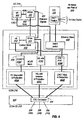
Switch controller 202 comprises acontrol card 214, a inter-connection (ICON)card 216, ICON- I/O card 218, a Control Interconnect Card (CIC card) 220 associated with thecontrol card 214 and a Facilities Card (FAC card) (not shown). TheICON card 216 provides the interface for connecting theswitch controller 202 to all peripheral shelf controllers on the other shelves 200, 204 in theswitch 108. TheCIC 220 provides an interface to communicate with line cards inswitch controller 202. - Fig. 2B illustrates
CSL 206 connections between various peripheral devices to theswitch controller 202. As shown, each high speedperipheral shelf 204B has a pair of redundant shelf controllers 210A and 210B each connecting the peripheral shelf 204 to an ICON I/O interface card 218 viaCSL 206. Similarly, eachperipheral shelf 204A has a pair of redundant shelf controllers 210A and 210B each connecting thePS 204A to the ICON I/O interface card 218, again viaCSL 206. As seen, the embodiment utilizes redundant cards and connections in its architecture. - Still referring to Fig. 2B, a
switching shelf 200A has ashelf controller 222 connecting theswitching shelf 200A to ICON I/O interface card 218. Also, aswitching shelf 200B has a shelf controller 220B connecting theswitching shelf 200B to ICON I/O interface card 218. The connection examples shown in Fig. 2B illustrate the flexibility in the architecture in accommodating many different types of peripheral devices and redundant connections. However, it will be understood the examples shown in Fig. 2B are not limiting. Many alternative designs are possible showing different interconnections. - Still referring to Fig. 2B, ICON I/O interface card 218A is connected to
ICON management card 216.ICON management card 216 is in turn connected to controlcard 214. Again, the embodiment may utilize redundant cards withinswitch controller 202 and may connect them to provide multiple paths between each component. - Aspects relating to the communication of signals between
control card 214 to each of peripheral shelf 204, high-speed peripheral shelf 204 and switching shelf 200 is now described. - As noted above,
switch controller 202 provides control operations forswitch 108. Control commands are initiated via elements in control card 214 (described later) and are converted to signals which are transmitted to the target shelves. - It will be appreciated that different control commands will have different bandwidth and timing requirements. In the embodiment, there are four categories of control commands which have different timing sensitivities. The first category of commands has a low bandwidth requirement for its transmission from the switch controller to the destination; however, the commands have a sensitive time requirements for transmission and receipt of the commands. This first category of commands includes commands such as reporting severe faults in a fabric and initiating switching of fabrics. A second category of commands relate to servicing functions for the
switch 108. These types of commands may have high bandwidth requirements, but may not have critical timing issues. Examples of the second category of commands include commands to download software, update local tables and initiate or tear down a connection. A third category of timing commands include time of day distribution commands. Commands in this third category are used during usage billing calculations. There may not be a critical timing issue for these commands. A fourth category of commands relates to clocking synchronization. It is necessary to synchronize clock signals amongst theswitch controller 202 and theperipheral shelves switching shelves - It will be appreciated that each of the four categories of timing commands may be carried over a single control transmission datastream. However, due to the conflicting features of the timing requirements for the categories, it will be appreciated that it may not always be possible to combine all of the four categories together. For example, the high bandwidth, low priority service requirements of the second category of command signals may conflict with the low bandwidth, high priority service requirements of the first category of commands.
- Accordingly, the embodiment provides four separate transmission systems for encoding and transmitting the control signals from the
switch controller 202 to the other shelves, namely high speed peripheral shelf 204,peripheral shelves 204B....204O, and switchingshelves - (i) for the first category of low bandwidth, high priority commands signals, an E1 communication transmission protocol is used;
- (ii) for the second category of high bandwidth, lower priority commands, an Ethernet signalling transmission protocol is used;
- (iii) for the third category of time of day distribution signalling, a real time signalling
(RTS) protocol is used which utilizes electrical characteristics for its signalling
per the known
RS 485 convention; and - (iv) for the fourth category of commands, commands are provided via an embedded E1 signalling transmission protocol. The fourth category utilizes features of a known signalling protocol (as will be described later) which is inherent to the E1 communication link used by the first category of commands.
-
- It will be appreciated that other signalling protocols may be used for any of the four categories of commands, as long as the selected protocols meet the requirements for their respective category, such as timing and bandwidth. It will be also appreciated that when possible, it may be possible to combine one or more of the four categories into a single or multiple set of signals, appropriately modulated on top of each other, to achieve both the transmission requirements for the respective category and also combining the physical transmissions into one or more communication links.
- Referring to Fig. 3A, for the embodiment, E1 transmissions are carried over two twisted pairs of
wire 302A, 302B with onetwisted pair 302A carrying communications downstream from theswitch controller 202 to the connected shelf and another twisted pair 302B of wire carrying E1 encoded communications from the shelf to theswitch controller 202. In the embodiment, the two sets of twisted pairs are grouped together as a set of four conductors twisted together. Similarly, for Ethernet communications, two pairs oftwisted wires switch controller 202 to the connected shelf, with one pair ofwires 310A providing a downstream link from theswitch controller 202 to the connected shelf and another twisted pair ofwires 310B to carry communications upstream from the connected shelf to theswitch controller 202. Again, the two pairs of conductors are grouped together as a set of four conductors twisted together. For RTS signals, a single pair oftwisted wires 318 is provided from theswitch controller 202 to the connected shelf. As this is a broadcast-type of transmission, no response is required from any of the shelves. Accordingly, no upstream communication link is provided for the RTS signalling. For the fourth category, appropriate signals inherent to the E1 protocol provided as part of the E1 transmission standard for the first category signals are utilized at each end of the existing E1 link. - Referring to Fig. 3A, each of the distinct transmission protocols, namely E1, Ethernet and RTS, are carried on separate conductors, but the embodiment physically groups together each of the three types of conductors together in a single common link. This link is
CSL 206, described earlier. InCSL 206,E1 cable 300 comprises twisted pairs ofconductors 302A and 302B. In Fig. 3A,conductors 302A and 302B are illustrated as separate pairs, but as described earlier, the embodiment has the two pairs twisted together.Conductors 302A and 302B are collectively shielded in ametal foil layer 304.Ethernet cable 308 comprises twisted pairs ofcables E1 cable 300,cables metal foil layer 312. TheRTS cable 316 comprises a twisted pair ofwires 318. In the embodiment, two pairs of conductors twisted together are provided incable 316; however, for the sake of clarity, only one pair ofwires 318 is illustrated in Fig. 3B. Again,twisted pair 318 is surrounded by ametal foil 320. Finally,cables metal foil lawyer 324 and ametal braid 326. An appropriate exterior sheathing may be provided to protect any or all of the cables. In other embodiments, the above noted pairs of conductors may not be twisted together. Accordingly, it will be appreciated thatCSL cable 206 individually isolates each cable from its neighbours and collectively isolates the set of cables from RFI and EMI external interference. It will be appreciated thatcable 206 provides a single run of groupedcables cable 206. Accordingly,cable 206 provides a single connection system forcontroller 202 to each shelf 204 and 200 which provides all four categories of communication signals.Cable 206 may be terminated at each end with a physically unique connector to prevent miscabling ofcable 206 between shelves and in incorrect orientations. It will be appreciated that the term forcable 316 is synonymous with other terms, such as conductor, connection and link. - Referring to Fig. 3B, further detail on the
RTS cable 318 is shown, for an exemplary connection betweenswitch controller 202 andHSPS 204A. To produce the signal that is carried uponRTS link 316, at the interface point ofICON card 218, the original RTS signal carried online 328 is provided todifferential amplifier 330. The voltage level of signals online 328 is generally 3.3 volts. Differential amplifier produces a differential signal modulating about zero volts. The differential signal is in RS485 format and has a value of approximately 300mV. The differential signal is provided to RTS link 318 onlines HSPS 204A,CSL 206 provides a connection todifferential receiver 332. The differential receiver converts the received signal onlines line 334. The output produced online 334 is a 3.3 volt signal. The signal can then be used byHSPS 204A. For RTS connections for the peripheral switch controller and the switching shelf controller, a comparable RTS connection, as described above, is provided. - Following is a description of each of the elements in the
switch controller 202 and each of the peripheral shelves, 204B, high speedperipheral shelf 204A and switching shelf 200. - First, a description is provided of each of the elements in each of the shelves related to the E1 transmissions. Referring to Fig. 4, in
switch controller 202,control card 214 comprisesmicroprocessor 400 andFPGA 402.ICON card 216 comprisesEthernet switch block 408,control block 410,transceiver block 416 andisolation modules 420. Incontrol block 410, microprocessor 412 operates software which controlsICON card 216. Periodically, the software operating onmicroprocessor 400 may initiate a command which falls into the first category of commands, described earlier. Accordingly, the software operating inmicroprocessor 400 sends to FPGA 402 via link 404 a message that a first category command is to be sent. TheFPGA 402 generates an appropriate message and sends it via 490 or 492 (depending on the data) toICON card 216. - For an E1 command, within
ICON card 216,FPGA 414 provides same to controlblock 410.Control block 410 comprises microprocessor 412 andFPGA 414. Accordingly, an E1 message is generated and the message is provided totransceiver block 416. Withintransceiver block 408, the E1 message is routed toE1 framer 418A. E1 framers are known in the art.E1 framer 418A frames the E1 message per the recognized protocol and sends it toexternal interface block 420. Withinexternal interface block 420, the E1 transmission is received by E1 magnetics andprotection block 422A which electrically isolates the signal from the rest of thecable 206. Next, the E1 signal is provided to a physical termination point in ICON I/O card 218, namelyCSL connector 424.CSL connector 424 has appropriate terminations which allow a connected CSL link 206 to connect itsE1 cable 300 to the appropriate terminal inCSL connector 424. From that point, the E1 communications are carried over to the connected shelf byCSL cable 206. - Referring to Fig. 5, elements relating to the processing of the E1 communication protocol are shown for high speed
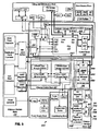
peripheral shelf 204A. First, CSL link 206 connects toexternal interface block 500 atCSL connector 502.CSL connector 502 provides an appropriate connection fromCSL cable 206 to the interface portion for E1 transmission protocol processing for high speedperipheral shelf 204A. Accordingly, from CSL connector 504, E1 signals are provided to E1 magnetics and protection block 504A which provides electrical isolation of high speedperipheral shelf 204A from E1 signals carried uponCSL link 206. Fromexternal interface block 500, the E1 communications stream is provided totransceiver block 506. Withintransceiver block 506, the E1 signals are received byE1 framer 508A which appropriately unframes the E1 signal. The unframed E1 signal is then provided to controlblock 510. Therein,microprocessor 512 andFPGA 514 collectively operate to decode the E1 signal to identify the message contained therein and the destination of the message into an appropriate DC signal, providing a midplane signal which can be provided to line card 516. - In the embodiment, a toggling signal is generated and sent by a shelf controller to indicate its activity status to its associated line card. The activity status of a shelf controller is either active, inactive, a request to be active or a fault. A request to be active is typically generated on startup of the switch. In particular, in a shelf controller the toggling signal is generated by
FPGA 514. For example, if the shelf controller is being switched from an active state to an inactive state, the signal provided byFPGA 514 to line card 516 is a "slow toggle" signal. If the shelf controller is being switched from an inactive state to an active state, the signal provided byFPGA 514 to line card 516 is be a "fast toggle" signal. If a "medium toggle" signal is generated byFPGA 514, a request to be active is sent from the shelf controller. If the signal is a DC value, i.e. no toggle, then an error condition is present in the shelf controller. - In the embodiment, the protocol parameters of E1 communications enables time sensitive commands to be encoded and sent from
switch controller 202 to various remote shelves. - It will be appreciated that communications from line card 516 destined for
switch controller 202 which are encoded in E1 format may be processed by the earlier described modules forcontroller 202 in a similar fashion, as described above but for the flow of data occurring in the upstream direction. Upstream E1 transmissions are carried onCSL link 206 via cables 302B. - Following is a description of Ethernet communications from
switch controller 202 to line card 516. Referring to Fig. 4, software operating onmicroprocessor 400 determines that a download of updated software, for example, is necessary for line card 516.Microprocessor 400 sends a message directly toICON card 216. InICON card 216, the Ethernet message is received atEthernet switch 408 and provided directly to theEthernet PHY block 418B oftransceiver block 416. Fromtransceiver block 416, the Ethernet encoded message is provided toexternal interface block 420. Therein, the signal is provided to Ethernet magnetics and protection block 424B. Therefrom, the Ethernet signal is provided toCSL connector 424 which has appropriate connections toCSL cable 206 tocables 308. From that point, the Ethernet message is sent overCSL 206 to the connectingHSPS 204A. - Referring to Fig. 5, the Ethernet message in
CSL 206 is received atexternal interface block 500 atCSL connector 502. The Ethernet stream is directed to Ethernet magnetics andprotection block 504B. Therefrom, the Ethernet message is provided to transceiver block 506 and EthernetPHY conversion block 508B. FromPHY block 508B, the Ethernet message is provided to Ethernet switch block 516. Ethernet switch block 516 routes the Ethernet message tomidplane interface block 518 which then provides the Ethernet signal to line card 516. - It will be appreciated that communications from line card 516 to switch
controller 202 which are carried over our Ethernet link may be processed by the above described Ethernet modules in a similar fashion as described above, but for the flow of data occurring in the upstream direction. Ethernet transmissions are carried over CSL link 206 viacables 310B. Ethernet messages may also be provided to local microprocessors in ICON card216 andshelf controller 210. - In the embodiment, it will be appreciated that Ethernet transmissions may be transmitted from its source directly to the line card 516. Whereas with E1 communications, in the embodiment it is not possible to send some transmissions from ultimate source to ultimate destination without having an intervening protocol introduced to transmit the message to the "last mile", i.e the component. It will be appreciated that in other embodiments, other modules may be provided to allow "end-to-end" transmissions of any given protocol for any given signal.
- The following is a description of the transmission of RTS signals from
switch controller 202 to line card 516. The RTS signalling system provides a time stamp to all line cards 516. The RTS pulse has an embedded date value. The RTS signal allows a local card to synchronize with a clock using an offset value contained in the signal. The time stamp provides 100 ms of synchronization accuracy between cards 516 on different shelves. To accomplish this, two counters are used in RTS receivers to generate a universal time stamp: a local high resolution (1 us) counter and a low resolution counter. The low resolution signal is sent over theRTS link 316. The receipt of the low-resolution signal provides a stimulus to initiate a free-running counter which is used to generate the high-resolution portion of the timestamp. For the low-resolution counter, it has a value derived from a PWM signal generated from theswitch controller 202. The sequence of values in the low resolution counter is a pseudo-random number and is provided in an accessible software table. Accordingly, a look-up must be performed at line card 516 to determine the offset time indicated by the low resolution counter. At line card 516 the result of this look-up is combined with the local high resolution counter to provide a local time stamp having micro-second precision. - Referring to Fig. 4, for a time stamp signal, software operating on
microprocessor 400 inswitch controller 202 sends a base time signal on Ethernet link 494 toICON card 216.FPGA 402 generates a pulse width modulation (PWM) signal encoding the RTS message and provides same toICON module 216 vialink 492. WithinICON module 216, the RTS message is received atcontrol block 410. ThereinFPGA 414 cause the generation of a broadcast signal which will be "fanned out" to each of the connected HSPS cards for 204A. Accordingly, in "fanning out" the signal,control block 410 provides the received RTS message toRS 485transmitter 422C intransceiver block 416. Fromtransceiver block 416, the message is provided toexternal interface block 420 andRS 485 isolation andprotection module 422C. From there, theisolation block 422C has a connection to the appropriate RTS links inCSL connector 424. Accordingly, the RTS signal is carried upon appropriate CSL cable(s) 206 andwires 316 to each shelf. - Referring to Fig. 5, at a particular shelf the RTS message is received from
CSL cable 206 atCSL connector 502 inexternal interface block 500. From theconnector 502, the RTS signal is provided toRS 485 isolation and protection block 504C which electrically isolates theHSPS 204A fromCSL 206. Fromexternal interface block 500, the RTS signal is provided totransceiver block 506. Intransceiver block 506, the signal is provided toRS 485 receivingblock 508C and then, the RTS signal is provided to controlblock 510. Therein,FPGA 514 generates signals to distribute the RTS signal locally to each connected line card 516 or other elements which have a microprocessor. - The following is a description of the fourth category of commands. As noted earlier, the embodiment provides synchronization for all clocks distributed in the system, namely the controller clocks on the
switch controller 202 and the each of the shelves. The following signalling method is used which is transmitted by piggy backing the signals on the E1 communications stream. - First, a description of the general parameters of the timing mechanism is provided. As each of the I/O sources are operating on different SONET rings, the embodiment provides a method of synchronizing all timing aspects amongst each of the rings. Essentially, the
switch controller 202 receives timing information from each of the distributed elements, namely line cards 516 etc. Initially an arbitrary clock signal is generated by theswitch controller 202 as the synchronization signal. Next, the peripheral shelf 204 recovers the timing signal from the E1 channel driven byswitch controller 202. Next, shelf controller 204 calculates a digital phase word and places the word in the TDM stream, which is transmitted to switchcontroller 202. Then switchcontroller 202 notifies shelf controller 204 of which line card 516 is to be used to calculate the digital phase word. Finally,ICON management card 216 utilizes the clock signal provided byswitch controller 202 to synchronize E1 framers such that all shelf controllers 204 and 200 receive the same synchronization signal. - It will be appreciated that the embodiment provides a single connection point between heterogeneous cabling systems having common beginning and termination points. Also, the embodiment provides a system of transmitting heterogeneous signalling protocols to various shelves. It will further be appreciated that the embodiment may be used between any shelves or components in the switch requiring a plurality of signalling systems.
- It is noted that those skilled in the art will appreciate that various modifications of detail may be made to the present embodiment, all of which would come within the scope of the invention.
Claims (7)
- A connection system for a communication switch comprising a controller and a plurality of shelves providing communication capabilities for said communication switch, said controller being able to communicate with each shelf of said plurality of shelves utilizing a plurality of categories of communication signals, said connection system comprising:wherein said plurality of connections are bundled together in a single, collective span of cable and each connection of said plurality of connections provides its individual category of said plurality of categories of communication signal independently of the other connections of said plurality of connections.a plurality of connections providing signalling links for said plurality of categories of communication signals between said controller and said each shelf of said plurality of shelves,
- A connection system according to claim 1 wherein
said single, collective span of cable comprises a first end having a connector adapted to provide connections for each connection of said plurality of connections to said controller and a second end having a second connector adapted to provide connections for each connection of said plurality of connections to said each shelf; and
wherein said first and second connectors have physical profiles which do not allow said first connector to be connected with said shelf and said second connector with said controller. - A connection system according to any one of claims 1 or 2 wherein one of said plurality of connections is adapted to carry E1 frame format signals.
- A connection system according to claim 3 wherein a second of said plurality of connections is adapted to carry Ethernet format signals.
- A connection system according to claim 4 wherein a third of said plurality of connections is adapted to carry RS 485 format signals.
- A connection system according to any one of claims 1 to 5 wherein one of said plurality of connections is adapted to carry timing synchronization signals for said communication switch.
- A connection system according to claim 6 wherein said timing synchronization signals comprise:a first set of timing signals generated by said controller and transmitted on said one of said plurality of connections to each of said plurality of shelves;a second set of response timing signals generated by each of said plurality of shelves and transmitted on said one of said plurality of connections to said controller, said second set of timing signals related to local timing signals related to each of said plurality of shelves; anda third set of synchronization signals generated by said controller and transmitted on said one of said plurality of connections to each of said plurality of shelves, said third set of synchronization signals synchronized to one of said local timing signals.
Applications Claiming Priority (4)
| Application Number | Priority Date | Filing Date | Title |
|---|---|---|---|
| CA2358037 | 2001-09-27 | ||
| CA002358037A CA2358037A1 (en) | 2001-09-27 | 2001-09-27 | System and method for a control services link for a multi-shelf node in a communication switch |
| US10/012,434 US7095735B2 (en) | 2001-09-27 | 2001-12-12 | System and method for a control services link for a multi-shelf node in a communication switch |
| US12434 | 2001-12-12 |
Publications (3)
| Publication Number | Publication Date |
|---|---|
| EP1326385A2 true EP1326385A2 (en) | 2003-07-09 |
| EP1326385A3 EP1326385A3 (en) | 2004-05-19 |
| EP1326385B1 EP1326385B1 (en) | 2006-07-26 |
Family
ID=25682739
Family Applications (1)
| Application Number | Title | Priority Date | Filing Date |
|---|---|---|---|
| EP02292375A Expired - Lifetime EP1326385B1 (en) | 2001-09-27 | 2002-09-26 | System and method for a service control link for a multi-shelf node in a communication switch |
Country Status (4)
| Country | Link |
|---|---|
| US (1) | US7653052B2 (en) |
| EP (1) | EP1326385B1 (en) |
| AT (1) | ATE334536T1 (en) |
| DE (1) | DE60213358T2 (en) |
Cited By (1)
| Publication number | Priority date | Publication date | Assignee | Title |
|---|---|---|---|---|
| EP1519505A3 (en) * | 2003-09-26 | 2006-06-07 | Alcatel | Multi-Shelf system clock synchronization |
Families Citing this family (6)
| Publication number | Priority date | Publication date | Assignee | Title |
|---|---|---|---|---|
| US7710866B2 (en) * | 2001-09-27 | 2010-05-04 | Alcatel-Lucent Canada Inc. | Method and apparatus for optimization of redundant link usage in a multi-shelf network element |
| US7619886B2 (en) * | 2001-09-27 | 2009-11-17 | Alcatel-Lucent Canada Inc. | Method and apparatus for providing a common support services infrastructure for a network element |
| US7382774B2 (en) * | 2005-05-31 | 2008-06-03 | Falco Anthony R | Bankover connection system |
| US8064200B1 (en) | 2008-04-16 | 2011-11-22 | Cyan Optics, Inc. | Cooling a chassis by moving air through a midplane between two sets of channels oriented laterally relative to one another |
| US8155520B1 (en) * | 2008-04-16 | 2012-04-10 | Cyan, Inc. | Multi-fabric shelf for a transport network |
| US8390993B1 (en) | 2008-04-16 | 2013-03-05 | Cyan, Inc. | Light source in chassis to provide frontal illumination of a faceplate on the chassis |
Citations (4)
| Publication number | Priority date | Publication date | Assignee | Title |
|---|---|---|---|---|
| US3997879A (en) * | 1975-12-24 | 1976-12-14 | Allen-Bradley Company | Fault processor for programmable controller with remote I/O interface racks |
| EP0687123A2 (en) * | 1994-06-10 | 1995-12-13 | Harris Corporation | Intgrated network switch supporting a wide range of functions |
| US5729546A (en) * | 1995-06-21 | 1998-03-17 | Cisco Systems, Inc. | Expandable communication cell bus for multiplexing and concentrating communication cell traffic onto high speed lines |
| US6421322B1 (en) * | 1997-11-17 | 2002-07-16 | Adc Telecommunications, Inc. | System and method for electronically identifying connections of a cross-connect system |
Family Cites Families (1)
| Publication number | Priority date | Publication date | Assignee | Title |
|---|---|---|---|---|
| CA2358037A1 (en) * | 2001-09-27 | 2003-03-27 | Alcatel Canada Inc. | System and method for a control services link for a multi-shelf node in a communication switch |
-
2002
- 2002-09-26 AT AT02292375T patent/ATE334536T1/en not_active IP Right Cessation
- 2002-09-26 DE DE60213358T patent/DE60213358T2/en not_active Expired - Lifetime
- 2002-09-26 EP EP02292375A patent/EP1326385B1/en not_active Expired - Lifetime
-
2006
- 2006-05-18 US US11/435,869 patent/US7653052B2/en not_active Expired - Fee Related
Patent Citations (4)
| Publication number | Priority date | Publication date | Assignee | Title |
|---|---|---|---|---|
| US3997879A (en) * | 1975-12-24 | 1976-12-14 | Allen-Bradley Company | Fault processor for programmable controller with remote I/O interface racks |
| EP0687123A2 (en) * | 1994-06-10 | 1995-12-13 | Harris Corporation | Intgrated network switch supporting a wide range of functions |
| US5729546A (en) * | 1995-06-21 | 1998-03-17 | Cisco Systems, Inc. | Expandable communication cell bus for multiplexing and concentrating communication cell traffic onto high speed lines |
| US6421322B1 (en) * | 1997-11-17 | 2002-07-16 | Adc Telecommunications, Inc. | System and method for electronically identifying connections of a cross-connect system |
Cited By (2)
| Publication number | Priority date | Publication date | Assignee | Title |
|---|---|---|---|---|
| EP1519505A3 (en) * | 2003-09-26 | 2006-06-07 | Alcatel | Multi-Shelf system clock synchronization |
| US7209530B2 (en) | 2003-09-26 | 2007-04-24 | Alcatei | Multi-shelf system clock synchronization |
Also Published As
| Publication number | Publication date |
|---|---|
| US7653052B2 (en) | 2010-01-26 |
| US20060274736A1 (en) | 2006-12-07 |
| EP1326385A3 (en) | 2004-05-19 |
| ATE334536T1 (en) | 2006-08-15 |
| EP1326385B1 (en) | 2006-07-26 |
| DE60213358T2 (en) | 2007-08-09 |
| DE60213358D1 (en) | 2006-09-07 |
Similar Documents
| Publication | Publication Date | Title |
|---|---|---|
| US7460482B2 (en) | Master-slave communications system and method for a network element | |
| US7526203B2 (en) | Apparatus and method for optical switching at an optical switch fabric | |
| EP0369690B1 (en) | Frame synchronization in a network of time multiplexed optical space switches | |
| US5787070A (en) | One for N redundancy in a communication system | |
| FI107204B (en) | Optical data network | |
| US5463623A (en) | Integrated wireless telecommunication and local area network system | |
| US7653052B2 (en) | System and method for a control services link for a multi-shelf node in a communication switch | |
| US5901136A (en) | System and method for controlling timing in a distributed digital cross-connect system | |
| EP2337372B1 (en) | High capacity switching system | |
| CA2326894A1 (en) | Voice and data apparatus comprising a selective tapping digital signal processing resource | |
| US7209477B2 (en) | Multi-subshelf control system and method for a network element | |
| US7233590B2 (en) | Switched channel-band network | |
| US5787085A (en) | Data transmission optimization system and method | |
| US6198720B1 (en) | Distributed digital cross-connect system and method | |
| US7095735B2 (en) | System and method for a control services link for a multi-shelf node in a communication switch | |
| US6501766B1 (en) | Generic bus system | |
| US7639655B2 (en) | Ethernet switch interface for use in optical nodes | |
| US6285687B1 (en) | Timing system and method for distributing a timing signal | |
| US5303267A (en) | Multipoint data communications system | |
| EP0953272B1 (en) | System and method for controlling timing in a distributed digital cross-connect system | |
| EP1298867B1 (en) | Master-slave communication system and method for a network element | |
| EP1298852B1 (en) | Multi-subshelf control system and method for a network element | |
| EP0950334B1 (en) | Distributed digital cross-connect system and method | |
| JPS59161163A (en) | Automatic remote supervisory device | |
| KR970002711B1 (en) | Small scale network termination unit for b-isdn |
Legal Events
| Date | Code | Title | Description |
|---|---|---|---|
| PUAI | Public reference made under article 153(3) epc to a published international application that has entered the european phase |
Free format text: ORIGINAL CODE: 0009012 |
|
| AK | Designated contracting states |
Designated state(s): AT BE BG CH CY CZ DE DK EE ES FI FR GB GR IE IT LI LU MC NL PT SE SK TR |
|
| AX | Request for extension of the european patent |
Extension state: AL LT LV MK RO SI |
|
| PUAL | Search report despatched |
Free format text: ORIGINAL CODE: 0009013 |
|
| AK | Designated contracting states |
Kind code of ref document: A3 Designated state(s): AT BE BG CH CY CZ DE DK EE ES FI FR GB GR IE IT LI LU MC NL PT SE SK TR |
|
| AX | Request for extension of the european patent |
Extension state: AL LT LV MK RO SI |
|
| 17P | Request for examination filed |
Effective date: 20041119 |
|
| 17Q | First examination report despatched |
Effective date: 20041217 |
|
| AKX | Designation fees paid |
Designated state(s): AT BE BG CH CY CZ DE DK EE ES FI FR GB GR IE IT LI LU MC NL PT SE SK TR |
|
| GRAP | Despatch of communication of intention to grant a patent |
Free format text: ORIGINAL CODE: EPIDOSNIGR1 |
|
| RTI1 | Title (correction) |
Free format text: SYSTEM AND METHOD FOR A SERVICE CONTROL LINK FOR A MULTI-SHELF NODE IN A COMMUNICATION SWITCH |
|
| GRAS | Grant fee paid |
Free format text: ORIGINAL CODE: EPIDOSNIGR3 |
|
| GRAA | (expected) grant |
Free format text: ORIGINAL CODE: 0009210 |
|
| AK | Designated contracting states |
Kind code of ref document: B1 Designated state(s): AT BE BG CH CY CZ DE DK EE ES FI FR GB GR IE IT LI LU MC NL PT SE SK TR |
|
| PG25 | Lapsed in a contracting state [announced via postgrant information from national office to epo] |
Ref country code: BE Free format text: LAPSE BECAUSE OF FAILURE TO SUBMIT A TRANSLATION OF THE DESCRIPTION OR TO PAY THE FEE WITHIN THE PRESCRIBED TIME-LIMIT Effective date: 20060726 Ref country code: CH Free format text: LAPSE BECAUSE OF FAILURE TO SUBMIT A TRANSLATION OF THE DESCRIPTION OR TO PAY THE FEE WITHIN THE PRESCRIBED TIME-LIMIT Effective date: 20060726 Ref country code: SK Free format text: LAPSE BECAUSE OF FAILURE TO SUBMIT A TRANSLATION OF THE DESCRIPTION OR TO PAY THE FEE WITHIN THE PRESCRIBED TIME-LIMIT Effective date: 20060726 Ref country code: FI Free format text: LAPSE BECAUSE OF FAILURE TO SUBMIT A TRANSLATION OF THE DESCRIPTION OR TO PAY THE FEE WITHIN THE PRESCRIBED TIME-LIMIT Effective date: 20060726 Ref country code: NL Free format text: LAPSE BECAUSE OF FAILURE TO SUBMIT A TRANSLATION OF THE DESCRIPTION OR TO PAY THE FEE WITHIN THE PRESCRIBED TIME-LIMIT Effective date: 20060726 Ref country code: LI Free format text: LAPSE BECAUSE OF FAILURE TO SUBMIT A TRANSLATION OF THE DESCRIPTION OR TO PAY THE FEE WITHIN THE PRESCRIBED TIME-LIMIT Effective date: 20060726 Ref country code: AT Free format text: LAPSE BECAUSE OF FAILURE TO SUBMIT A TRANSLATION OF THE DESCRIPTION OR TO PAY THE FEE WITHIN THE PRESCRIBED TIME-LIMIT Effective date: 20060726 Ref country code: CZ Free format text: LAPSE BECAUSE OF FAILURE TO SUBMIT A TRANSLATION OF THE DESCRIPTION OR TO PAY THE FEE WITHIN THE PRESCRIBED TIME-LIMIT Effective date: 20060726 |
|
| REG | Reference to a national code |
Ref country code: GB Ref legal event code: FG4D |
|
| REG | Reference to a national code |
Ref country code: CH Ref legal event code: EP |
|
| REG | Reference to a national code |
Ref country code: IE Ref legal event code: FG4D |
|
| REF | Corresponds to: |
Ref document number: 60213358 Country of ref document: DE Date of ref document: 20060907 Kind code of ref document: P |
|
| PG25 | Lapsed in a contracting state [announced via postgrant information from national office to epo] |
Ref country code: IE Free format text: LAPSE BECAUSE OF NON-PAYMENT OF DUE FEES Effective date: 20060926 |
|
| PGFP | Annual fee paid to national office [announced via postgrant information from national office to epo] |
Ref country code: ES Payment date: 20060928 Year of fee payment: 5 |
|
| PG25 | Lapsed in a contracting state [announced via postgrant information from national office to epo] |
Ref country code: MC Free format text: LAPSE BECAUSE OF NON-PAYMENT OF DUE FEES Effective date: 20060930 |
|
| PG25 | Lapsed in a contracting state [announced via postgrant information from national office to epo] |
Ref country code: BG Free format text: LAPSE BECAUSE OF FAILURE TO SUBMIT A TRANSLATION OF THE DESCRIPTION OR TO PAY THE FEE WITHIN THE PRESCRIBED TIME-LIMIT Effective date: 20061026 Ref country code: SE Free format text: LAPSE BECAUSE OF FAILURE TO SUBMIT A TRANSLATION OF THE DESCRIPTION OR TO PAY THE FEE WITHIN THE PRESCRIBED TIME-LIMIT Effective date: 20061026 Ref country code: DK Free format text: LAPSE BECAUSE OF FAILURE TO SUBMIT A TRANSLATION OF THE DESCRIPTION OR TO PAY THE FEE WITHIN THE PRESCRIBED TIME-LIMIT Effective date: 20061026 |
|
| PG25 | Lapsed in a contracting state [announced via postgrant information from national office to epo] |
Ref country code: ES Free format text: LAPSE BECAUSE OF FAILURE TO SUBMIT A TRANSLATION OF THE DESCRIPTION OR TO PAY THE FEE WITHIN THE PRESCRIBED TIME-LIMIT Effective date: 20061106 |
|
| ET | Fr: translation filed | ||
| PG25 | Lapsed in a contracting state [announced via postgrant information from national office to epo] |
Ref country code: PT Free format text: LAPSE BECAUSE OF FAILURE TO SUBMIT A TRANSLATION OF THE DESCRIPTION OR TO PAY THE FEE WITHIN THE PRESCRIBED TIME-LIMIT Effective date: 20061226 |
|
| NLV1 | Nl: lapsed or annulled due to failure to fulfill the requirements of art. 29p and 29m of the patents act | ||
| PLBE | No opposition filed within time limit |
Free format text: ORIGINAL CODE: 0009261 |
|
| STAA | Information on the status of an ep patent application or granted ep patent |
Free format text: STATUS: NO OPPOSITION FILED WITHIN TIME LIMIT |
|
| 26N | No opposition filed |
Effective date: 20070427 |
|
| PG25 | Lapsed in a contracting state [announced via postgrant information from national office to epo] |
Ref country code: GR Free format text: LAPSE BECAUSE OF FAILURE TO SUBMIT A TRANSLATION OF THE DESCRIPTION OR TO PAY THE FEE WITHIN THE PRESCRIBED TIME-LIMIT Effective date: 20061027 |
|
| PG25 | Lapsed in a contracting state [announced via postgrant information from national office to epo] |
Ref country code: EE Free format text: LAPSE BECAUSE OF FAILURE TO SUBMIT A TRANSLATION OF THE DESCRIPTION OR TO PAY THE FEE WITHIN THE PRESCRIBED TIME-LIMIT Effective date: 20060726 |
|
| PG25 | Lapsed in a contracting state [announced via postgrant information from national office to epo] |
Ref country code: TR Free format text: LAPSE BECAUSE OF FAILURE TO SUBMIT A TRANSLATION OF THE DESCRIPTION OR TO PAY THE FEE WITHIN THE PRESCRIBED TIME-LIMIT Effective date: 20060726 Ref country code: LU Free format text: LAPSE BECAUSE OF NON-PAYMENT OF DUE FEES Effective date: 20060926 |
|
| PG25 | Lapsed in a contracting state [announced via postgrant information from national office to epo] |
Ref country code: CY Free format text: LAPSE BECAUSE OF FAILURE TO SUBMIT A TRANSLATION OF THE DESCRIPTION OR TO PAY THE FEE WITHIN THE PRESCRIBED TIME-LIMIT Effective date: 20060726 |
|
| REG | Reference to a national code |
Ref country code: FR Ref legal event code: CD Owner name: ALCATEL-LUCENT CANADA INC Effective date: 20130723 |
|
| REG | Reference to a national code |
Ref country code: FR Ref legal event code: GC Effective date: 20130820 |
|
| REG | Reference to a national code |
Ref country code: GB Ref legal event code: 732E Free format text: REGISTERED BETWEEN 20130912 AND 20130918 |
|
| REG | Reference to a national code |
Ref country code: FR Ref legal event code: RG Effective date: 20141015 |
|
| REG | Reference to a national code |
Ref country code: FR Ref legal event code: PLFP Year of fee payment: 14 |
|
| REG | Reference to a national code |
Ref country code: FR Ref legal event code: PLFP Year of fee payment: 15 |
|
| REG | Reference to a national code |
Ref country code: FR Ref legal event code: PLFP Year of fee payment: 16 |
|
| REG | Reference to a national code |
Ref country code: FR Ref legal event code: PLFP Year of fee payment: 17 |
|
| PGFP | Annual fee paid to national office [announced via postgrant information from national office to epo] |
Ref country code: DE Payment date: 20180920 Year of fee payment: 17 Ref country code: IT Payment date: 20180925 Year of fee payment: 17 Ref country code: FR Payment date: 20180924 Year of fee payment: 17 |
|
| PGFP | Annual fee paid to national office [announced via postgrant information from national office to epo] |
Ref country code: GB Payment date: 20180919 Year of fee payment: 17 |
|
| REG | Reference to a national code |
Ref country code: DE Ref legal event code: R119 Ref document number: 60213358 Country of ref document: DE |
|
| PG25 | Lapsed in a contracting state [announced via postgrant information from national office to epo] |
Ref country code: DE Free format text: LAPSE BECAUSE OF NON-PAYMENT OF DUE FEES Effective date: 20200401 |
|
| PG25 | Lapsed in a contracting state [announced via postgrant information from national office to epo] |
Ref country code: IT Free format text: LAPSE BECAUSE OF NON-PAYMENT OF DUE FEES Effective date: 20190926 |
|
| GBPC | Gb: european patent ceased through non-payment of renewal fee |
Effective date: 20190926 |
|
| PG25 | Lapsed in a contracting state [announced via postgrant information from national office to epo] |
Ref country code: GB Free format text: LAPSE BECAUSE OF NON-PAYMENT OF DUE FEES Effective date: 20190926 Ref country code: FR Free format text: LAPSE BECAUSE OF NON-PAYMENT OF DUE FEES Effective date: 20190930 |