EP1324569B1 - Foldable electronic apparatus - Google Patents
Foldable electronic apparatus Download PDFInfo
- Publication number
- EP1324569B1 EP1324569B1 EP01310922A EP01310922A EP1324569B1 EP 1324569 B1 EP1324569 B1 EP 1324569B1 EP 01310922 A EP01310922 A EP 01310922A EP 01310922 A EP01310922 A EP 01310922A EP 1324569 B1 EP1324569 B1 EP 1324569B1
- Authority
- EP
- European Patent Office
- Prior art keywords
- edge
- adjacent
- open configuration
- operating controls
- open
- Prior art date
- Legal status (The legal status is an assumption and is not a legal conclusion. Google has not performed a legal analysis and makes no representation as to the accuracy of the status listed.)
- Expired - Lifetime
Links
- 230000003213 activating effect Effects 0.000 description 1
- 239000003086 colorant Substances 0.000 description 1
- 238000010586 diagram Methods 0.000 description 1
- 230000010365 information processing Effects 0.000 description 1
- 238000010295 mobile communication Methods 0.000 description 1
- 230000003068 static effect Effects 0.000 description 1
- 230000000007 visual effect Effects 0.000 description 1
Images


Classifications
-
- G—PHYSICS
- G06—COMPUTING; CALCULATING OR COUNTING
- G06F—ELECTRIC DIGITAL DATA PROCESSING
- G06F1/00—Details not covered by groups G06F3/00 - G06F13/00 and G06F21/00
- G06F1/16—Constructional details or arrangements
- G06F1/1613—Constructional details or arrangements for portable computers
- G06F1/1633—Constructional details or arrangements of portable computers not specific to the type of enclosures covered by groups G06F1/1615 - G06F1/1626
- G06F1/1675—Miscellaneous details related to the relative movement between the different enclosures or enclosure parts
- G06F1/1677—Miscellaneous details related to the relative movement between the different enclosures or enclosure parts for detecting open or closed state or particular intermediate positions assumed by movable parts of the enclosure, e.g. detection of display lid position with respect to main body in a laptop, detection of opening of the cover of battery compartment
-
- G—PHYSICS
- G06—COMPUTING; CALCULATING OR COUNTING
- G06F—ELECTRIC DIGITAL DATA PROCESSING
- G06F1/00—Details not covered by groups G06F3/00 - G06F13/00 and G06F21/00
- G06F1/16—Constructional details or arrangements
- G06F1/1613—Constructional details or arrangements for portable computers
- G06F1/1615—Constructional details or arrangements for portable computers with several enclosures having relative motions, each enclosure supporting at least one I/O or computing function
- G06F1/1616—Constructional details or arrangements for portable computers with several enclosures having relative motions, each enclosure supporting at least one I/O or computing function with folding flat displays, e.g. laptop computers or notebooks having a clamshell configuration, with body parts pivoting to an open position around an axis parallel to the plane they define in closed position
-
- G—PHYSICS
- G06—COMPUTING; CALCULATING OR COUNTING
- G06F—ELECTRIC DIGITAL DATA PROCESSING
- G06F1/00—Details not covered by groups G06F3/00 - G06F13/00 and G06F21/00
- G06F1/16—Constructional details or arrangements
- G06F1/1613—Constructional details or arrangements for portable computers
- G06F1/1633—Constructional details or arrangements of portable computers not specific to the type of enclosures covered by groups G06F1/1615 - G06F1/1626
- G06F1/1662—Details related to the integrated keyboard
- G06F1/1671—Special purpose buttons or auxiliary keyboards, e.g. retractable mini keypads, keypads or buttons that remain accessible at closed laptop
-
- H—ELECTRICITY
- H04—ELECTRIC COMMUNICATION TECHNIQUE
- H04M—TELEPHONIC COMMUNICATION
- H04M1/00—Substation equipment, e.g. for use by subscribers
- H04M1/02—Constructional features of telephone sets
- H04M1/0202—Portable telephone sets, e.g. cordless phones, mobile phones or bar type handsets
- H04M1/0206—Portable telephones comprising a plurality of mechanically joined movable body parts, e.g. hinged housings
- H04M1/0208—Portable telephones comprising a plurality of mechanically joined movable body parts, e.g. hinged housings characterized by the relative motions of the body parts
- H04M1/0214—Foldable telephones, i.e. with body parts pivoting to an open position around an axis parallel to the plane they define in closed position
- H04M1/0216—Foldable in one direction, i.e. using a one degree of freedom hinge
-
- E—FIXED CONSTRUCTIONS
- E05—LOCKS; KEYS; WINDOW OR DOOR FITTINGS; SAFES
- E05D—HINGES OR SUSPENSION DEVICES FOR DOORS, WINDOWS OR WINGS
- E05D15/00—Suspension arrangements for wings
- E05D15/48—Suspension arrangements for wings allowing alternative movements
- E05D15/50—Suspension arrangements for wings allowing alternative movements for opening at either of two opposite edges
- E05D15/507—Suspension arrangements for wings allowing alternative movements for opening at either of two opposite edges by detachment of the hinge from the wing or the frame
-
- E—FIXED CONSTRUCTIONS
- E05—LOCKS; KEYS; WINDOW OR DOOR FITTINGS; SAFES
- E05Y—INDEXING SCHEME ASSOCIATED WITH SUBCLASSES E05D AND E05F, RELATING TO CONSTRUCTION ELEMENTS, ELECTRIC CONTROL, POWER SUPPLY, POWER SIGNAL OR TRANSMISSION, USER INTERFACES, MOUNTING OR COUPLING, DETAILS, ACCESSORIES, AUXILIARY OPERATIONS NOT OTHERWISE PROVIDED FOR, APPLICATION THEREOF
- E05Y2201/00—Constructional elements; Accessories therefor
- E05Y2201/60—Suspension or transmission members; Accessories therefor
- E05Y2201/622—Suspension or transmission members elements
- E05Y2201/624—Arms
-
- E—FIXED CONSTRUCTIONS
- E05—LOCKS; KEYS; WINDOW OR DOOR FITTINGS; SAFES
- E05Y—INDEXING SCHEME ASSOCIATED WITH SUBCLASSES E05D AND E05F, RELATING TO CONSTRUCTION ELEMENTS, ELECTRIC CONTROL, POWER SUPPLY, POWER SIGNAL OR TRANSMISSION, USER INTERFACES, MOUNTING OR COUPLING, DETAILS, ACCESSORIES, AUXILIARY OPERATIONS NOT OTHERWISE PROVIDED FOR, APPLICATION THEREOF
- E05Y2999/00—Subject-matter not otherwise provided for in this subclass
Definitions
- the present invention relates to electronic devices, and, more particularly, to electronic devices that can physically be manipulated between different configurations.
- the invention has been developed primarily for use in the fields of personal digital assistants and mobile telephone handsets, and will be described hereinafter with reference to these applications. However, it will be appreciated that the invention has application in a number of alternative electronic devices.
- US Patent No. 5,494,447 which relates to a hinge assembly for electronic devices that allows for lineal and rotational adjustment of each device part.
- European Patent Application Publication No. 0807879 relates to an information processing apparatus having a main body and a lid body configured so that the lid body may be configured between a closed state, a stacked state, a double screen state and an inverted state.
- a device foldable between a first open configuration, a closed configuration and a second open configuration including:a first body portion having a first edge, a first face and a second edge opposite the first edge; a second body portion having a third edge, a second face and a fourth edge opposite the third edge; a first connecting member, one end of which is hingedly connected to the first edge and an opposite end of which is hingedly connected to the third edge; and a second member, one end of which is hingedly connected to the second edge and an opposite end of which is hingedly connected to the fourth edge; the apparatus being configured such that: in the closed configuration the first edge is adjacent the fourth edge and the second edge is adjacent the third edge; in the first open configuration the second edge is adjacent the third edge and the first edge is not adjacent the fourth edge; and in the second open configuration the first edge is adjacent the fourth edge and the second edge is not adjacent the third edge; characterized in that the device is an electronic apparatus, and in that in the first open configuration a first set
- At least some of the operating controls are on at least one of the members, such that they are accessible on that member only in one of the two open configurations.
- both sides of at least one of the members includes one or more of the operating controls, such that that member reveals the operating controls on one of its sides when in the first open configuration and on the other of its sides when in the second open configuration.
- one or more of members has a through hole or other through contour that surrounds or lies adjacent one or more of the operating controls when in one of the open configurations, such that indicia on the member adjacent the hole or shape labels that operating control when in that open configuration.
- the hole or contour surrounds one or more of the operating controls in the first open configurations, and one or more other operating controls in the second open configuration, such that indicia adjacent the hole or shape label the operating controls when adjacent the operating controls in each of the respective open configurations.
- FIG. 1 there is shown an electronic apparatus 100 foldable between a first open configuration, a closed configuration and a second open configuration. It will be appreciated that the apparatus has not been drawn to scale and has somewhat looser connections than would be the case in an engineered version, to enable a better understanding of the multi-way hinge connection.
- the apparatus 100 includes a first body portion 102 having a first edge 104, a first face 106 and a second edge 108 substantially opposite the first edge.
- a second body portion 110 has a third edge 112, a second face 114 and a fourth edge 116 substantially opposite the third edge.
- a first connecting member 118 has one end 120 hingedly connected to the first edge 104 by a first hinge 105 and an opposite end 122 hingedly connected to the third edge 112 by a third hinge 113.
- a second member 123 has one end 124 hingedly connected to the second edge 108 by a second hinge 109 and an opposite end 126 which is hingedly connected to the fourth edge 116 by a fourth hinge 117.
- a first set of operating controls 128 are disposed on the first face 106 and a second set of operating controls 130 are disposed on the second face 114.
- the first set 128 includes operating buttons 132 and the second set 130 includes buttons 134.
- the first face 106 also includes an operating display 136.
- the apparatus of figure 1 In a closed position (not shown) the apparatus of figure 1 has the first edge adjacent the fourth edge and the second edge adjacent the third edge.
- the operating controls and the display are then enclosed and protected by the first body portion 102 and the second body portion 110.
- the display When the device is opened into a first open configuration, as shown in Figure 1, the display is uncovered, as are the first and second sets of controls.
- the user can then implement any combination of data required.
- data can be input via either or both sets of buttons. It will be appreciated that a greater number of operating control buttons will be desirable in such an embodiment, but for the purposes of simplicity, only a small number of such buttons are shown.
- the fourth and first edges are first swung back together around the axes of the second and third hinges.
- the second and third edges are then separated from each other and the apparatus rotated into the second open position about the axes of the first and fourth hinges.
- the first and fourth hinge axes will be substantially coincident, as will those of the second and third hinge axes, to ensure that the device closes completely between the two open configurations.
- the members are too long for this to occur, for the sake of understanding the mechanics of the invention.
- the first member covers the second set of operating controls, such that a user cannot see or access them. Also, the operating display is obscured by the position of the second member.
- the different side of the members, and the areas that they obscure in different open configurations, can be coloured differently, and can include indicia that is revealed or obscured depending upon which of the two open configurations are in use. This provides the ability for a visual appearance that is customisable depending upon the configuration.
- FIG. 2 to 5 An alternative embodiment is shown in Figures 2 to 5, which shows a design that is correctly engineered such that the apparatus closed properly intermediate the first and second open configurations.
- the main distinction is that there are third 136 and fourth 138 members that operate similar to the respective first and second members. This enables a more stable apparatus that is more resistant to undesirable torsional forces in use, as well as providing more options for changing the appearance of the operating controls in the two open configurations.
- buttons 140 themselves include operating controls in the form of buttons 140. Whilst such buttons are shown on all sides of the members, it will be appreciated that this is optional, and that such buttons or other operating controls can appear on either or both sides of one or more of the members (or not at all, as in the Figure 1 embodiment).
- the apparatus in this embodiment is a handset for two-way video telephony, and therefore includes a camera 142 and a display 143 for displaying video from another device to which the displayed apparatus is connected via, for example, a wireless network.
- Figure 2 shows the apparatus in the closed configuration.
- Figure 3 shows the apparatus partially opening into the first open configuration.
- Figure 4 shows the device completely in the first open configuration.
- Figure 5 shows the apparatus completely in the second open configuration. It will be noted that alternative controls are now visible on each of the members, whilst the controls that were visible in Figures 3 and 4 are hidden. Similarly, the members have obscured some controls on the first and second faces that were visible in the first open configuration, and revealed some others that they obscured in the first configuration. In a preferred form, the controls are visually brighter in Figures 3 and 4, due to the colours chosen for the sides of the members that are shown in those Figures. Figure 5 reveals a more sombre colour scheme. The sparkling version could be, for example, a game, whilst the more sombre version could implement the more conservative video telephony configuration.
- positions of the members in the two configurations can also reveal or obscure indicia, such as numbers, letters or diagrams, that can modify the way a user understands an operating control.
- a member can have a first function label on one side (visible in the first open configuration) and a second function label on the other side. These labels are disposed adjacent an operating control to which they relate, when the apparatus is in the configuration that allows that function to be implemented by activating that operating control.
- the apparatus in one orientation can be configured to act as a mobile communication handset, whilst in another it can operate as a PDA.
- one configuration can be a language translator and the other a calculator. It will be understood that although the preferred embodiment incorporates a telecommunications handset in at least one embodiment, any combination of devices or operating configurations can be implemented.
Landscapes
- Engineering & Computer Science (AREA)
- Computer Hardware Design (AREA)
- Theoretical Computer Science (AREA)
- Physics & Mathematics (AREA)
- General Engineering & Computer Science (AREA)
- General Physics & Mathematics (AREA)
- Human Computer Interaction (AREA)
- Signal Processing (AREA)
- Mathematical Physics (AREA)
- Telephone Set Structure (AREA)
- Pivots And Pivotal Connections (AREA)
- Casings For Electric Apparatus (AREA)
- Closing And Opening Devices For Wings, And Checks For Wings (AREA)
- Fittings On The Vehicle Exterior For Carrying Loads, And Devices For Holding Or Mounting Articles (AREA)
- Telephone Function (AREA)
Abstract
Description
- The present invention relates to electronic devices, and, more particularly, to electronic devices that can physically be manipulated between different configurations.
- The invention has been developed primarily for use in the fields of personal digital assistants and mobile telephone handsets, and will be described hereinafter with reference to these applications. However, it will be appreciated that the invention has application in a number of alternative electronic devices.
- It is common for personal digital assistants and some mobile telephones to incorporate a hinging mechanism for allowing an open and closed configuration. In the closed configuration, some or all of any operating display is obscured (and protected), and some or all controls such as input keys and buttons may be covered to prevent accidental use of, or damage to, the device when not in use. Once the device is opened about the hinge, the user can access all of the controls and see an operating display.
- Whilst convenient in some cases, such devices can only operate in a single open configuration with static options as far as operating controls are concerned.
- Reference is made to US Patent No. 5,494,447 which relates to a hinge assembly for electronic devices that allows for lineal and rotational adjustment of each device part. European Patent Application Publication No. 0807879 relates to an information processing apparatus having a main body and a lid body configured so that the lid body may be configured between a closed state, a stacked state, a double screen state and an inverted state.
- It would be desirable if more than one operating mode could be provided to enable a wider range of control options.
- According to the invention, there is provided a device foldable between a first open configuration, a closed configuration and a second open configuration, the apparatus including:a first body portion having a first edge, a first face and a second edge opposite the first edge; a second body portion having a third edge, a second face and a fourth edge opposite the third edge; a first connecting member, one end of which is hingedly connected to the first edge and an opposite end of which is hingedly connected to the third edge; and a second member, one end of which is hingedly connected to the second edge and an opposite end of which is hingedly connected to the fourth edge; the apparatus being configured such that: in the closed configuration the first edge is adjacent the fourth edge and the second edge is adjacent the third edge; in the first open configuration the second edge is adjacent the third edge and the first edge is not adjacent the fourth edge; and in the second open configuration the first edge is adjacent the fourth edge and the second edge is not adjacent the third edge; characterized in that the device is an electronic apparatus, and in that in the first open configuration a first set of operating controls is revealed, and in the second open configuration a second set of operating controls is revealed, and the appearance or operation of the first and second sets of operative controls is changed by either or both of the members obscuring or revealing operating controls in first and second respective open configurations. respective open configurations.
- Preferably, at least some of the operating controls are on at least one of the members, such that they are accessible on that member only in one of the two open configurations.
- Preferably, both sides of at least one of the members includes one or more of the operating controls, such that that member reveals the operating controls on one of its sides when in the first open configuration and on the other of its sides when in the second open configuration.
- In a preferred embodiment, one or more of members has a through hole or other through contour that surrounds or lies adjacent one or more of the operating controls when in one of the open configurations, such that indicia on the member adjacent the hole or shape labels that operating control when in that open configuration.
- In an alternative embodiment, the hole or contour surrounds one or more of the operating controls in the first open configurations, and one or more other operating controls in the second open configuration, such that indicia adjacent the hole or shape label the operating controls when adjacent the operating controls in each of the respective open configurations.
-
- Figure 1 is a perspective view of an electronic apparatus according to the invention, with detail omitted for clarity;
- Figure 2 is a perspective view of an alternative embodiment of an electronic apparatus according to the invention, in the closed position;
- Figure 3 is a perspective view of the electronic apparatus of Figure 2, partially opened towards a first open configuration;
- Figure 4 is a perspective view of the electronic apparatus of Figure 2 and 3, in the first open configuration; and
- Figure 5 is a perspective view of the electronic apparatus of Figures 2 to 4, in a second open configuration.
- Referring to Figure 1, there is shown an
electronic apparatus 100 foldable between a first open configuration, a closed configuration and a second open configuration. It will be appreciated that the apparatus has not been drawn to scale and has somewhat looser connections than would be the case in an engineered version, to enable a better understanding of the multi-way hinge connection. - The
apparatus 100 includes afirst body portion 102 having afirst edge 104, afirst face 106 and asecond edge 108 substantially opposite the first edge. Asecond body portion 110 has athird edge 112, asecond face 114 and afourth edge 116 substantially opposite the third edge. - A first connecting
member 118 has oneend 120 hingedly connected to thefirst edge 104 by afirst hinge 105 and anopposite end 122 hingedly connected to thethird edge 112 by athird hinge 113. Asecond member 123 has oneend 124 hingedly connected to thesecond edge 108 by asecond hinge 109 and anopposite end 126 which is hingedly connected to thefourth edge 116 by afourth hinge 117. - A first set of
operating controls 128 are disposed on thefirst face 106 and a second set ofoperating controls 130 are disposed on thesecond face 114. In this embodiment, thefirst set 128 includesoperating buttons 132 and thesecond set 130 includesbuttons 134. - The
first face 106 also includes anoperating display 136. - In a closed position (not shown) the apparatus of figure 1 has the first edge adjacent the fourth edge and the second edge adjacent the third edge. The operating controls and the display are then enclosed and protected by the
first body portion 102 and thesecond body portion 110. - When the device is opened into a first open configuration, as shown in Figure 1, the display is uncovered, as are the first and second sets of controls. The user can then implement any combination of data required. For example, if the invention is embodied in a personal digital assistant (PDA), data can be input via either or both sets of buttons. It will be appreciated that a greater number of operating control buttons will be desirable in such an embodiment, but for the purposes of simplicity, only a small number of such buttons are shown.
- To fold the device into a second open configuration, the fourth and first edges are first swung back together around the axes of the second and third hinges. The second and third edges are then separated from each other and the apparatus rotated into the second open position about the axes of the first and fourth hinges. It will be appreciated that in a properly engineered product, the first and fourth hinge axes will be substantially coincident, as will those of the second and third hinge axes, to ensure that the device closes completely between the two open configurations. However, in this case the members are too long for this to occur, for the sake of understanding the mechanics of the invention.
- In the second open configuration, the first member covers the second set of operating controls, such that a user cannot see or access them. Also, the operating display is obscured by the position of the second member.
- The different side of the members, and the areas that they obscure in different open configurations, can be coloured differently, and can include indicia that is revealed or obscured depending upon which of the two open configurations are in use. This provides the ability for a visual appearance that is customisable depending upon the configuration.
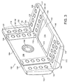
- An alternative embodiment is shown in Figures 2 to 5, which shows a design that is correctly engineered such that the apparatus closed properly intermediate the first and second open configurations. The main distinction is that there are third 136 and fourth 138 members that operate similar to the respective first and second members. This enables a more stable apparatus that is more resistant to undesirable torsional forces in use, as well as providing more options for changing the appearance of the operating controls in the two open configurations.
- In this embodiment, the members themselves include operating controls in the form of
buttons 140. Whilst such buttons are shown on all sides of the members, it will be appreciated that this is optional, and that such buttons or other operating controls can appear on either or both sides of one or more of the members (or not at all, as in the Figure 1 embodiment). - The apparatus in this embodiment is a handset for two-way video telephony, and therefore includes a
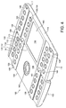
camera 142 and adisplay 143 for displaying video from another device to which the displayed apparatus is connected via, for example, a wireless network. - Figure 2 shows the apparatus in the closed configuration. Figure 3 shows the apparatus partially opening into the first open configuration. Figure 4 shows the device completely in the first open configuration.
- Figure 5 shows the apparatus completely in the second open configuration. It will be noted that alternative controls are now visible on each of the members, whilst the controls that were visible in Figures 3 and 4 are hidden. Similarly, the members have obscured some controls on the first and second faces that were visible in the first open configuration, and revealed some others that they obscured in the first configuration. In a preferred form, the controls are visually brighter in Figures 3 and 4, due to the colours chosen for the sides of the members that are shown in those Figures. Figure 5 reveals a more sombre colour scheme. The colourful version could be, for example, a game, whilst the more sombre version could implement the more conservative video telephony configuration.
- It will be appreciated that the positions of the members in the two configurations can also reveal or obscure indicia, such as numbers, letters or diagrams, that can modify the way a user understands an operating control. For example, a member can have a first function label on one side (visible in the first open configuration) and a second function label on the other side. These labels are disposed adjacent an operating control to which they relate, when the apparatus is in the configuration that allows that function to be implemented by activating that operating control.
- Various exemplary forms of the invention are envisaged. For example, in one orientation the apparatus can be configured to act as a mobile communication handset, whilst in another it can operate as a PDA. In other embodiments, one configuration can be a language translator and the other a calculator. It will be understood that although the preferred embodiment incorporates a telecommunications handset in at least one embodiment, any combination of devices or operating configurations can be implemented.
- It will be appreciated by those skilled in the art that the described embodiments are exemplary only. Accordingly, the scope of the invention is not to be limited by the embodiments described in this specification.
Claims (5)
- A device (100) foldable between a first open configuration, a closed configuration and a second open configuration, the apparatus including:a first body portion (102) having a first edge (104), a first face (106) and a second edge (108) opposite the first edge;a second body portion (110) having a third edge (112), a second face (114) and a fourth edge (116) opposite the third edge;a first connecting member (118), one end of which is hingedly connected to the first edge and an opposite end of which is hingedly connected to the third edge; anda second connecting member (123), one end of which is hingedly connected to the second edge and an opposite end of which is hingedly connected to the fourth edge;the apparatus being configured such that:in the closed configuration the first edge is adjacent the fourth edge and the second edge is adjacent the third edge;in the first open configuration the second edge is adjacent the third edge and the first edge is not adjacent the fourth edge; andin the second open configuration the first edge is adjacent the fourth edge and the second edge is not adjacent the third edge;characterized in that the device is an electronic apparatus, and in that in the first open configuration a first set of operating controls (128) is revealed, and in the second open configuration a second set of operating controls (130) is revealed, and the appearance or operation of the first and second sets of operative controls is changed by either or both of the connecting members obscuring or revealing operating controls in first and second respective open configurations.
- A device according to claim 1, wherein at least some of the operating controls are on at least one of the members, such that they are accessible on that member only in one of the two open configurations.
- A device according to claim 2, wherein both sides of at least one of the members includes one or more of the operating controls, such that that member reveals the operating controls on one of its sides when in the first open configuration and on the other of its sides when in the second open configuration.
- A device according to claim 1 or 2, wherein one or more of members has a through hole or other through contour that surrounds or lies adjacent one or more of the operating controls when in one of the open configurations, such that indicia on the member adjacent the hole or shape labels that operating control when in that open configuration.
- A device according to claim 4, wherein the hole or contour surrounds one or more of the operating controls in the first open configurations, and one or more other operating controls in the second open configuration, such that indicia adjacent the hole or shape label the operating controls when adjacent the operating controls in each of the respective open configurations.
Priority Applications (3)
| Application Number | Priority Date | Filing Date | Title |
|---|---|---|---|
| DE60121975T DE60121975T2 (en) | 2001-12-28 | 2001-12-28 | Hinged electronic device |
| AT01310922T ATE335351T1 (en) | 2001-12-28 | 2001-12-28 | HINGED ELECTRONIC DEVICE |
| EP01310922A EP1324569B1 (en) | 2001-12-28 | 2001-12-28 | Foldable electronic apparatus |
Applications Claiming Priority (1)
| Application Number | Priority Date | Filing Date | Title |
|---|---|---|---|
| EP01310922A EP1324569B1 (en) | 2001-12-28 | 2001-12-28 | Foldable electronic apparatus |
Publications (2)
| Publication Number | Publication Date |
|---|---|
| EP1324569A1 EP1324569A1 (en) | 2003-07-02 |
| EP1324569B1 true EP1324569B1 (en) | 2006-08-02 |
Family
ID=8182581
Family Applications (1)
| Application Number | Title | Priority Date | Filing Date |
|---|---|---|---|
| EP01310922A Expired - Lifetime EP1324569B1 (en) | 2001-12-28 | 2001-12-28 | Foldable electronic apparatus |
Country Status (3)
| Country | Link |
|---|---|
| EP (1) | EP1324569B1 (en) |
| AT (1) | ATE335351T1 (en) |
| DE (1) | DE60121975T2 (en) |
Family Cites Families (6)
| Publication number | Priority date | Publication date | Assignee | Title |
|---|---|---|---|---|
| US4132034A (en) * | 1977-10-25 | 1979-01-02 | Siclen William C Van | Refrigerator door with double acting hinge |
| FR2562599A1 (en) * | 1984-04-06 | 1985-10-11 | Bride Marcel | Two-way opening device for doors, leaves or coverings for any building or object requiring access from two opposite sides |
| US5103376A (en) * | 1991-02-19 | 1992-04-07 | At&T Bell Laboratories | Dual position computer arrangement |
| AU6496594A (en) * | 1993-03-26 | 1994-10-24 | Khalil S. Zaidan | Hinge assembly for electronic devices |
| DE4416370A1 (en) * | 1993-08-03 | 1995-02-09 | Dux Juergen Dipl Designer | Folding map |
| JP3222764B2 (en) * | 1996-05-17 | 2001-10-29 | シャープ株式会社 | Information processing device |
-
2001
- 2001-12-28 DE DE60121975T patent/DE60121975T2/en not_active Expired - Lifetime
- 2001-12-28 AT AT01310922T patent/ATE335351T1/en not_active IP Right Cessation
- 2001-12-28 EP EP01310922A patent/EP1324569B1/en not_active Expired - Lifetime
Also Published As
| Publication number | Publication date |
|---|---|
| EP1324569A1 (en) | 2003-07-02 |
| DE60121975D1 (en) | 2006-09-14 |
| DE60121975T2 (en) | 2007-03-01 |
| ATE335351T1 (en) | 2006-08-15 |
Similar Documents
| Publication | Publication Date | Title |
|---|---|---|
| KR101098618B1 (en) | Composition open and close type mobile communication terminal | |
| EP1186111B1 (en) | Personal digital assistant/telephone combination device | |
| EP1161062B1 (en) | Foldable electronic device | |
| US7158817B2 (en) | Portable terminal | |
| US7443979B2 (en) | Portable communication terminal having a housing capable of both sliding and swinging | |
| KR100993095B1 (en) | Foldable portable device | |
| US7184796B2 (en) | Personal communication device having a built in projection display | |
| US20010003707A1 (en) | Portable radio apparatus with additional display unit | |
| KR20040021366A (en) | Portable information phone with expansion data inputting unit | |
| CN101068266B (en) | Portable communication terminal for games and user interfacing device thereof | |
| KR20080035709A (en) | A triple folder type cellular phone with flexible display | |
| KR20020087847A (en) | Foldable keyboard for mobile communications device | |
| US7450968B2 (en) | Mobile communication device with slide portion | |
| EP1710986B1 (en) | Folder-type portable communication device having sliding display unit | |
| US7532915B2 (en) | Electronic apparatus having three modes of operation | |
| KR20060039750A (en) | Slide type mobile communication terminal having cover that opening and shutting for random angle is available | |
| EP1324569B1 (en) | Foldable electronic apparatus | |
| KR20020012880A (en) | Folder type portable flat display device | |
| US20050134568A1 (en) | Method and system for providing a rotated keyboard and angled display in a hand-held computing device | |
| KR20080088079A (en) | Wireless mobile terminal | |
| JP2001358811A (en) | Portable information terminal equipment | |
| KR100628744B1 (en) | Device for opening slider of slide type telecommunication terminal | |
| KR100592182B1 (en) | Folder type mobile phone which rotates an angle of 360 degrees | |
| KR200230378Y1 (en) | Double cover of mobile communication apparatus | |
| KR20040060566A (en) | Mobile phone |
Legal Events
| Date | Code | Title | Description |
|---|---|---|---|
| PUAI | Public reference made under article 153(3) epc to a published international application that has entered the european phase |
Free format text: ORIGINAL CODE: 0009012 |
|
| AK | Designated contracting states |
Designated state(s): AT BE CH CY DE DK ES FI FR GB GR IE IT LI LU MC NL PT SE TR |
|
| AX | Request for extension of the european patent |
Extension state: AL LT LV MK RO SI |
|
| 17P | Request for examination filed |
Effective date: 20031230 |
|
| AKX | Designation fees paid |
Designated state(s): AT BE CH CY DE DK ES FI FR GB GR IE IT LI LU MC NL PT SE TR |
|
| GRAP | Despatch of communication of intention to grant a patent |
Free format text: ORIGINAL CODE: EPIDOSNIGR1 |
|
| GRAS | Grant fee paid |
Free format text: ORIGINAL CODE: EPIDOSNIGR3 |
|
| GRAA | (expected) grant |
Free format text: ORIGINAL CODE: 0009210 |
|
| AK | Designated contracting states |
Kind code of ref document: B1 Designated state(s): AT BE CH CY DE DK ES FI FR GB GR IE IT LI LU MC NL PT SE TR |
|
| PG25 | Lapsed in a contracting state [announced via postgrant information from national office to epo] |
Ref country code: IT Free format text: LAPSE BECAUSE OF FAILURE TO SUBMIT A TRANSLATION OF THE DESCRIPTION OR TO PAY THE FEE WITHIN THE PRESCRIBED TIME-LIMIT;WARNING: LAPSES OF ITALIAN PATENTS WITH EFFECTIVE DATE BEFORE 2007 MAY HAVE OCCURRED AT ANY TIME BEFORE 2007. THE CORRECT EFFECTIVE DATE MAY BE DIFFERENT FROM THE ONE RECORDED. Effective date: 20060802 Ref country code: NL Free format text: LAPSE BECAUSE OF FAILURE TO SUBMIT A TRANSLATION OF THE DESCRIPTION OR TO PAY THE FEE WITHIN THE PRESCRIBED TIME-LIMIT Effective date: 20060802 Ref country code: LI Free format text: LAPSE BECAUSE OF FAILURE TO SUBMIT A TRANSLATION OF THE DESCRIPTION OR TO PAY THE FEE WITHIN THE PRESCRIBED TIME-LIMIT Effective date: 20060802 Ref country code: CH Free format text: LAPSE BECAUSE OF FAILURE TO SUBMIT A TRANSLATION OF THE DESCRIPTION OR TO PAY THE FEE WITHIN THE PRESCRIBED TIME-LIMIT Effective date: 20060802 Ref country code: FI Free format text: LAPSE BECAUSE OF FAILURE TO SUBMIT A TRANSLATION OF THE DESCRIPTION OR TO PAY THE FEE WITHIN THE PRESCRIBED TIME-LIMIT Effective date: 20060802 Ref country code: BE Free format text: LAPSE BECAUSE OF FAILURE TO SUBMIT A TRANSLATION OF THE DESCRIPTION OR TO PAY THE FEE WITHIN THE PRESCRIBED TIME-LIMIT Effective date: 20060802 Ref country code: AT Free format text: LAPSE BECAUSE OF FAILURE TO SUBMIT A TRANSLATION OF THE DESCRIPTION OR TO PAY THE FEE WITHIN THE PRESCRIBED TIME-LIMIT Effective date: 20060802 |
|
| REG | Reference to a national code |
Ref country code: GB Ref legal event code: FG4D |
|
| REG | Reference to a national code |
Ref country code: CH Ref legal event code: EP |
|
| REG | Reference to a national code |
Ref country code: IE Ref legal event code: FG4D |
|
| REF | Corresponds to: |
Ref document number: 60121975 Country of ref document: DE Date of ref document: 20060914 Kind code of ref document: P |
|
| PG25 | Lapsed in a contracting state [announced via postgrant information from national office to epo] |
Ref country code: SE Free format text: LAPSE BECAUSE OF FAILURE TO SUBMIT A TRANSLATION OF THE DESCRIPTION OR TO PAY THE FEE WITHIN THE PRESCRIBED TIME-LIMIT Effective date: 20061102 Ref country code: DK Free format text: LAPSE BECAUSE OF FAILURE TO SUBMIT A TRANSLATION OF THE DESCRIPTION OR TO PAY THE FEE WITHIN THE PRESCRIBED TIME-LIMIT Effective date: 20061102 |
|
| PG25 | Lapsed in a contracting state [announced via postgrant information from national office to epo] |
Ref country code: ES Free format text: LAPSE BECAUSE OF FAILURE TO SUBMIT A TRANSLATION OF THE DESCRIPTION OR TO PAY THE FEE WITHIN THE PRESCRIBED TIME-LIMIT Effective date: 20061113 |
|
| PG25 | Lapsed in a contracting state [announced via postgrant information from national office to epo] |
Ref country code: IE Free format text: LAPSE BECAUSE OF NON-PAYMENT OF DUE FEES Effective date: 20061228 |
|
| PG25 | Lapsed in a contracting state [announced via postgrant information from national office to epo] |
Ref country code: MC Free format text: LAPSE BECAUSE OF NON-PAYMENT OF DUE FEES Effective date: 20061231 |
|
| NLV1 | Nl: lapsed or annulled due to failure to fulfill the requirements of art. 29p and 29m of the patents act | ||
| PG25 | Lapsed in a contracting state [announced via postgrant information from national office to epo] |
Ref country code: PT Free format text: LAPSE BECAUSE OF FAILURE TO SUBMIT A TRANSLATION OF THE DESCRIPTION OR TO PAY THE FEE WITHIN THE PRESCRIBED TIME-LIMIT Effective date: 20070102 |
|
| ET | Fr: translation filed | ||
| REG | Reference to a national code |
Ref country code: CH Ref legal event code: PL |
|
| PLBE | No opposition filed within time limit |
Free format text: ORIGINAL CODE: 0009261 |
|
| STAA | Information on the status of an ep patent application or granted ep patent |
Free format text: STATUS: NO OPPOSITION FILED WITHIN TIME LIMIT |
|
| 26N | No opposition filed |
Effective date: 20070503 |
|
| PG25 | Lapsed in a contracting state [announced via postgrant information from national office to epo] |
Ref country code: GR Free format text: LAPSE BECAUSE OF FAILURE TO SUBMIT A TRANSLATION OF THE DESCRIPTION OR TO PAY THE FEE WITHIN THE PRESCRIBED TIME-LIMIT Effective date: 20061103 |
|
| PG25 | Lapsed in a contracting state [announced via postgrant information from national office to epo] |
Ref country code: LU Free format text: LAPSE BECAUSE OF NON-PAYMENT OF DUE FEES Effective date: 20061228 Ref country code: TR Free format text: LAPSE BECAUSE OF FAILURE TO SUBMIT A TRANSLATION OF THE DESCRIPTION OR TO PAY THE FEE WITHIN THE PRESCRIBED TIME-LIMIT Effective date: 20060802 |
|
| PG25 | Lapsed in a contracting state [announced via postgrant information from national office to epo] |
Ref country code: CY Free format text: LAPSE BECAUSE OF FAILURE TO SUBMIT A TRANSLATION OF THE DESCRIPTION OR TO PAY THE FEE WITHIN THE PRESCRIBED TIME-LIMIT Effective date: 20060802 |
|
| PGFP | Annual fee paid to national office [announced via postgrant information from national office to epo] |
Ref country code: FR Payment date: 20091221 Year of fee payment: 9 Ref country code: GB Payment date: 20091223 Year of fee payment: 9 |
|
| PGFP | Annual fee paid to national office [announced via postgrant information from national office to epo] |
Ref country code: DE Payment date: 20091224 Year of fee payment: 9 |
|
| GBPC | Gb: european patent ceased through non-payment of renewal fee |
Effective date: 20101228 |
|
| REG | Reference to a national code |
Ref country code: FR Ref legal event code: ST Effective date: 20110831 |
|
| PG25 | Lapsed in a contracting state [announced via postgrant information from national office to epo] |
Ref country code: FR Free format text: LAPSE BECAUSE OF NON-PAYMENT OF DUE FEES Effective date: 20110103 |
|
| PG25 | Lapsed in a contracting state [announced via postgrant information from national office to epo] |
Ref country code: GB Free format text: LAPSE BECAUSE OF NON-PAYMENT OF DUE FEES Effective date: 20101228 Ref country code: DE Free format text: LAPSE BECAUSE OF NON-PAYMENT OF DUE FEES Effective date: 20110701 |
|
| REG | Reference to a national code |
Ref country code: DE Ref legal event code: R119 Ref document number: 60121975 Country of ref document: DE Effective date: 20110701 |