EP1318689A2 - Communication control system, communication control method, base station and mobile station - Google Patents
Communication control system, communication control method, base station and mobile station Download PDFInfo
- Publication number
- EP1318689A2 EP1318689A2 EP20020027548 EP02027548A EP1318689A2 EP 1318689 A2 EP1318689 A2 EP 1318689A2 EP 20020027548 EP20020027548 EP 20020027548 EP 02027548 A EP02027548 A EP 02027548A EP 1318689 A2 EP1318689 A2 EP 1318689A2
- Authority
- EP
- European Patent Office
- Prior art keywords
- packet
- base station
- radio network
- state
- circuit
- Prior art date
- Legal status (The legal status is an assumption and is not a legal conclusion. Google has not performed a legal analysis and makes no representation as to the accuracy of the status listed.)
- Granted
Links
Images


Classifications
-
- H—ELECTRICITY
- H04—ELECTRIC COMMUNICATION TECHNIQUE
- H04W—WIRELESS COMMUNICATION NETWORKS
- H04W28/00—Network traffic management; Network resource management
- H04W28/02—Traffic management, e.g. flow control or congestion control
- H04W28/10—Flow control between communication endpoints
-
- H—ELECTRICITY
- H04—ELECTRIC COMMUNICATION TECHNIQUE
- H04L—TRANSMISSION OF DIGITAL INFORMATION, e.g. TELEGRAPHIC COMMUNICATION
- H04L47/00—Traffic control in data switching networks
- H04L47/10—Flow control; Congestion control
- H04L47/24—Traffic characterised by specific attributes, e.g. priority or QoS
-
- H—ELECTRICITY
- H04—ELECTRIC COMMUNICATION TECHNIQUE
- H04W—WIRELESS COMMUNICATION NETWORKS
- H04W72/00—Local resource management
- H04W72/12—Wireless traffic scheduling
-
- H—ELECTRICITY
- H04—ELECTRIC COMMUNICATION TECHNIQUE
- H04W—WIRELESS COMMUNICATION NETWORKS
- H04W72/00—Local resource management
- H04W72/50—Allocation or scheduling criteria for wireless resources
- H04W72/52—Allocation or scheduling criteria for wireless resources based on load
-
- H—ELECTRICITY
- H04—ELECTRIC COMMUNICATION TECHNIQUE
- H04W—WIRELESS COMMUNICATION NETWORKS
- H04W28/00—Network traffic management; Network resource management
- H04W28/02—Traffic management, e.g. flow control or congestion control
- H04W28/10—Flow control between communication endpoints
- H04W28/14—Flow control between communication endpoints using intermediate storage
Definitions
- the present invention relates to a communication control system and a communication control method in packet mobile communication, and to abase station and a mobile station, which are suitable for being applied thereto.
- Traffic admission control is an essential technique to prevent congestion from occurring in the network, to ensure the stability of the network and to support Qos (Quality of Service), by controlling the traffic coming into a network.
- Qos Quality of Service
- the admission control of the traffic flowing in a radio link (network) is indispensable.
- ATM Asynchronous Transfer Mode
- buffer queue average length (refer to "Congestion prevention device and method thereof using RED” : JPP2001-111556 A), or buffer queue usage rate (refer to "Congestion control system in intelligent network”: JP P2000-358068) is used.
- the amount of radio resources creates a bottleneck more frequently than the capacity of the queue.
- An object of the invention is to control the traffic that flows in a radio link to ensure the stability of the network as well as to prevent the deterioration of communication quality due to the transmission of packets exceeding the capacity thereof, and to increase communication volume.
- Another object of the invention is to increase communication quality by carrying out "traffic admission control" in accordance with the state of use of radio resources and the traffic type of a packet.
- the gist of a first characteristic of the invention is a communication control system in a packet mobile communication that transmits a downlink packet from a base station to a mobile station via a radio network, wherein the base station comprises a transmission determiner for determining whether or not to transmit the downlink packet to the radio network in accordance with the state of congestion of the radio network and the traffic type of the downlink packet.
- the transmission determiner estimates the state of congestion of the radio network in accordance with the state of use of transmission power resources in the base station.
- the transmission determiner estimates the state of congestion of the radio network by comparing a predetermined threshold set for each traffic type of the downlink packet with the state of use of transmission power resources in the base station.
- the traffic type is identified by means of a code point of a DiffServ IP packet (DSCP).
- DSCP DiffServ IP packet
- the gist of a second characteristic of the invention is a communication control system in a packet mobile communication that transmits an uplink packet from a mobile station to a base station via a radio network
- the base station comprises an admission determiner for determining whether or not to admit the uplink packet that is transmitted from the mobile station via the radio network in accordance with the state of congestion of the radio network and the traffic type of the uplink packet, and a notifier for notifying the determined result to the mobile station
- the mobile station comprises a transmission determiner for determining whether or not to transmit the uplink packet to the radio network in accordance with the notified result.
- the admission determiner estimate the state of congestion of the radio network in accordance with the state of use of reception power resources in the base station.
- the admission determiner estimates the state of congestion of the radio network by comparing a predetermined threshold set for each traffic type of the uplink packet with the state of use of reception power resources in the base station.
- the traffic type is identified by means of a code point of a DiffServ IP packet (DSCP).
- DSCP DiffServ IP packet
- the gist of a third characteristic of the invention is a communication control method in a packet mobile communication that transmits a downlink packet from a base station to a mobile station via a radio network comprising a step of A) determining, in the base station, whether or not to transmit the downlink packet to the radio network in accordance with the state of congestion of the radio network and the traffic type of the downlink packet.
- the gist of a fourth characteristic of the invention is a communication control method in a packet mobile communication that transmits an uplink packet from a mobile station to a base station via a radio network, comprising the steps of: A) determining, in the base station, whether or not to admit the uplink packet transmitted from the mobile station via the radio network in accordance with the state of congestion of the radio network and the traffic type of the uplink packet; B) notifying, from the base station, the determined result to the mobile station; and C) determining, in the mobile station, whether or not to transmit the uplink packet to the radio network in accordance with the notified result.
- the gist of a fifth characteristic of the invention is a base station that transmits a downlink packet to a mobile station via a radio network comprising a transmission determiner for determining whether or not to transmit the downlink packet to the radio network in accordance with the state of congestion of the radio network and the traffic type of the downlink packet.
- the gist of a sixth characteristic of the invention is a base station that receives an uplink packet from a mobile station via a radio network comprising an admission determiner for determining whether or not to admit the uplink packet transmitted from the mobile station via the radio network in accordance with the state of congestion of the radio network and the traffic type of the uplink packet, and a notifier for notifying the determined result to the mobile station.
- the gist of a seventh characteristic of the invention is a mobile station that transmits an uplink packet to a base station via a radio network comprising a transmission determiner for determining whether or not to transmit the uplink packet to the radio network by the base station in accordance with the state of congestion of the radio network and the traffic type of the uplink packet.
- FIG. 1 is an illustration showing a packet mobile communication environment including a communication control system according to an embodiment of the invention.
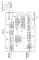
- FIG. 2 is a functional block diagram of a base station according to an embodiment of the invention.
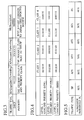
- FIG. 3 is a diagram showing traffic types according to an embodiment of the invention.
- FIG. 4 is a diagram showing traffic types according to an embodiment of the invention.
- FIG. 5 is a diagram showing an admission threshold for each traffic type according to an embodiment of the invention.
- FIG. 6 is a functional block diagram of a mobile station according to an embodiment of the invention.
- FIG. 7 is a flowchart diagram illustrating an operation of the base station when a communication control system according to an embodiment of the invention performs a traffic admission control with respect to a downlink packet.
- FIG. 8 is a flowchart diagram illustrating an operation of the base station when a communication control system according to an embodiment of the invention performs a traffic admission control with respect to an uplink packet.
- FIG. 9 is a flowchart diagram illustrating an operation of the mobile station when a communication control system according to an embodiment of the invention performs a traffic admission control with respect to a downlink packet.
- FIG. 1 is an illustration showing a packet mobile communication environment including the communication control system according to the embodiment of the invention.
- the packet mobile communication environment shown in FIG. 1 is configured with a base station 10 and a plurality of mobile stations 30 1 to 30 n .
- the plurality of mobile stations 30 1 to 30 n are connected to the base station 10, downlink signals 1 1 to 1 n are transmitted from the base station 10 to the plurality of mobile stations 30 1 to 30 n , and uplink signals 2 1 to 2 n are transmitted from the plurality of mobile stations 30 1 to 30 n to the base station 10.
- the communication control system In the packet mobile communication environment, in which a downlink packet 3 (downlink signal 1) is transmitted from the base station 10 to a mobile station 30 and an uplink packet 4 (uplink signal 2) is transmitted from the mobile station 30 to the base station 10 via a radio network, the communication control system according to the embodiment performs traffic admission control and network congestion control. The above is achieved by the functions provided to the base station 10 and the plurality of mobile stations 30 1 to 30 n .
- the base station 10 comprises a packet admission determination circuit 11, a signal multiplexing circuit 12, an encoding circuit 13, a modulating circuit 14, a down average transmission power measuring circuit 15, a circulator 16, a radio antenna 17, an up average reception power measuring circuit 18, a packet admission circuit 19, a demodulating circuit 20, a decoding circuit 21, a signal separating circuit 22, and an admission estimation result notifying circuit 23.
- the packet admission determination circuit 11 constitutes a transmission determiner configured to determine whether or not to transmit a downlink packet 3 to the radio network according to the state of congestion of the radio network and the traffic type of the downlink packet 3.
- the up average reception power measuring circuit 18 and the admission estimation result notifying circuit 23 constitute an admission determiner configured to determine whether or not to admit the uplink packet 4 transmitted from the mobile station 30 via the radio network according to the state of congestion of the radio network and the traffic type of the uplink packet 4, and a notifier configured to notify the determined result to the mobile station 30.
- the packet admission determination circuit 11 which is connected to the signal multiplexing circuit 12 and to the down average transmission power measuring circuit 15, estimates the network state of congestion according to the down average transmission power transferred from the down average transmission power measuring circuit 15 and to the traffic type of the downlink packet 3.
- the packet admission determination circuit 11 determines whether or not to admit the downlink packet 3 received from the superior network (a switching center, a radio network controller or the like) based on the estimated result, and transfers the downlink packet 3, that it is determined to admit, to the signal multiplexing circuit 12.
- the superior network a switching center, a radio network controller or the like
- the traffic type of the packet is identified by a "code point of a DiffServ IP packet: Diffserv Code Point (DSCP)" that is set in the packet header of the relevant packet.
- DSCP Diffserv Code Point
- the traffic type of the packet may be determined in such manner that the traffic type is notified at the time of reserving radio resources, and so on.
- the traffic types of the packets used in the embodiment will be described.
- three types are defined; i.e., an "EF (Expedited Forwarding) type” , an “AF (Assured Forwarding) type” and a “BE (Best Effort) type”.
- the "AF type” is classified into four classes (class 1 to 4) in accordance with priority (packet transmission speed, buffer length or the like).
- the four classes are categorized into three levels (level 1 to 3) respectively on the basis of discard priority.
- the "DSCP” of a packet of the "EF type” is "101110"
- the "DSCP” of a packet of the "AF type” is "XXXYYO”
- the "DSCP” of a packet of the "BE type” is "000000”.
- the "DSCP” of a packet of the "AF type/class 1/level 1" is "001010"
- the "DSCP” of a packet of the "AF type/class 1/level 2" is "001100”
- the "DSCP” of a packet of the "AF type/class 1/level 3" is "001110".
- the "DSCP” of a packet of the "AF type/class 2/level 1" is "010010” ; the "DSCP” of a packet of the "AF type/class 2/level 2" is “010100”; and the "DSCP” of a packet of the "AF type/class 2/level 3" is "010110".
- the "DSCP” of a packet of the "AF type/class 3/level 1" is "011010"; the "DSCP” of a packet of the "AF type/class 3/level 2" is "011100” ; and the "DSCP” of a packet of the "AF type/class 3/level 3" is "011110".
- the "DSCP” of a packet of the "AF type/class 4/level 1" is "100010"; the "DSCP” of a packet of the "AF type/class 4/level 2" is "100100”; and the "DSCP” of a packet of the "AF type/class 4/level 3" is "100110".
- the "EF type” defines the packets classified in the highest class in quality and priority.
- the "AF type” defines the packets classified in the class next in priority to the "EF type”.
- the "BE type” defines best-effort type packets.
- AF1 type the "AF type/class 1/level 1 to 3”
- AF2 type the "AF type/class 2/level 1 to 3”
- AF3 type the "AF type/class 4/level 1 to 3”
- AF4 type the "AF type/class 4/level 1 to 3”
- packets of "EF type” are defined as “real-time type” packets.
- the other traffic type packets are defined as “non-real-time type” packets.
- the packet admission determination circuit 11 calculates the "down radio resources usage rate (state of use of transmission power resources in the base station 10) R" in order to estimate the network state of congestion .
- down radio resources usage rate R means the proportion of the "down maximum transmission power" occupied by "down average transmission power”.
- down average transmission power means a time average of the down transmission power per predetermined period of time.
- down average transmission power means a time average of the down transmission power for each time slot within each frame that has already been transmitted by the base station 10.
- down maximum transmission power means a maximum value of the power by which the base station 10 can transmit the downlink signal 1.
- the packet admission determination circuit 11 determines to admit the downlink packet 3.
- the packet admission determination circuit 11 determines not to admit the downlink packet 3 in the case where the downlink packet 3 is real time traffic (i.e., packet of "EF type"); and determines to buffer the downlink packet 3 in the case where the downlink packet 3 is non-real-time traffic (i.e. packet other than "EF type").
- FIG. 5 shows admission threshold N i for each traffic type.
- the symbol “i” denotes a traffic type ("EF type”, “AF4 type”, “AF3 type “, “AF2 type”, “AF1 type” or "BE type”).
- the admission threshold N EF is set to 90%; the admission threshold N AF4 is set to 80%; the admission threshold N AF3 is set to 70%; the admission threshold N AF2 is set to 60%; the admission threshold N AF1 is set to 50%; and the admission threshold N BE is set to 40%.
- the packet admission determination circuit 11 renews the radio resources usage rate R in accordance with the down average transmission power from the down average transmission power measuring circuit 15 at every predetermined period of time (for example, every frame).
- the signal multiplexing circuit 12 is connected to the packet admission determination circuit 11, the encoding circuit 13, and the admission estimation result notifying circuit 23; and multiplexes the downlink packet 3 from the packet admission determination circuit 11 and an admission estimation result from the admission estimation result notifying circuit 23, and transmits it to the encoding circuit 13.
- the encoding circuit 13 is connected to the signal multiplexing circuit 12 and the modulating circuit 14; and encodes the multiplexed signal from the signal multiplexing circuit 12, and transmits it to the modulating circuit 14.
- the modulating circuit 14 is connected to the encoding circuit 13, the down average transmission power measuring circuit 15, and the circulator 16; and modulates the encoded signal from the encoding circuit 13, and transmits it to the down average transmission power measuring circuit 15 and the circulator 16.
- the down average transmission power measuring circuit 15 is connected to the packet admission determination circuit 11 and the modulating circuit 14; and monitors the modulated signal from the modulating circuit 14 to measure the down average transmission power. The measured down average transmission power is transmitted to the packet admission determination circuit 11.
- the down average transmission power measuring circuit 15 measures the down average transmission power at every predetermined period of time (for example, at every time slot within the frame).
- the circulator 16 is connected to the modulating circuit 14, the radio antenna 17, the up average reception power measuring circuit 18 and the packet admission determination circuit 19; and switches between the transmission process of the downlink signal 1 transferred from the modulating circuit 14 to the radio antenna 17, and the reception process of the uplink signal 2 transferred from the radio antenna 17 to the packet admission determination circuit 19 and the up average reception power measuring circuit 18.
- the up average reception power measuring circuit 18 is connected to the circulator 16 and the admission estimation result notifying circuit 23; and monitors the uplink signal 2 from the circulator 16 to measure the up average reception power, and transmits the measured up average reception power to the admission estimation result notifying circuit 23.
- the up average reception power measuring circuit 18 measures the up average reception power every predetermined period of time (for example, every time slot in the frame).
- the up average reception power measuring circuit 18 may measure the average value of "SIR (Signal to Interference Power Ratio)" every predetermined period of time, as the up average reception power, in place of measuring the average value of the up average reception power level at every predetermined period of time.
- SIR Signal to Interference Power Ratio
- the packet admission circuit 19 is connected to the circulator 16 and the demodulating circuit 20; and admits the uplink signal 2 from the circulator 16, to transmit the admitted uplink signal 2 to the demodulating circuit 20.
- the demodulating circuit 20 is connected to the packet admission circuit 19 and the decoding circuit 21; and demodulates the uplink signal 2 from the packet admission circuit 19, and transfers it to the decoding circuit 21.
- the decoding circuit 21 is connected to the demodulating circuit 20 and the signal separating circuit 22; and decodes the demodulated signal from the demodulating circuit 20, and transmits it to the signal separating circuit 22.
- the signal separating circuit 22 is connected to the decoding circuit 21; and separates the decoded signal from the decoding circuit 21 and extracts the uplink packet 4 to transmit the extracted uplink packet 4 to the superior network.
- the admission estimation result notifying circuit 23 is connected to the signal multiplexing circuit 12 and the up average reception power measuring circuit 18.
- the admission estimation result notifying circuit 23 estimates the state of congestion of the radio network in accordance with the up average reception power from the up average reception power measuring circuit 18; determines whether or not to receive the uplink packet 4 of each traffic type based on the estimated result, and transmits the determined admission estimation result (to receive or not to receive) to the signal multiplexing circuit 12.
- the admission estimation result notifying circuit 23 calculates the "up radio resources usage rate (state of use of reception power resources in the base station 10) R".
- up radio resources usage rate R means the proportion of the "up maximum reception power” occupied by "up average reception power”
- up average reception power means the time average of the up reception power at every predetermined period of time, for example, the time average of the up reception power in each time slot in the frame that has been received by the base station 10.
- up maximum reception power means the maximum value of power by which the base station 10 can receive the uplink signal 2.
- the admission estimation result notifying circuit 23 determines to admit the uplink packet 4 (uplink signal 2) of the traffic type i.
- the admission estimation result notifying circuit 23 determines not to admit the uplink packet 4 (uplink signal 2) of the traffic type i.
- the mobile station 30 comprises a packet input circuit 31, a traffic type check circuit 32, an encoding circuit 33, a modulating circuit 34, a circulator 35, a signal separating circuit 36, an admission Y/N judgment circuit 37, a transmission timing determination circuit 38, a demodulating circuit 39, a decoding circuit 40 and a packet output circuit 41.
- the admission Y/N judgment circuit 37 constitutes a transmission determiner configured to determine whether or not to transmit the uplink packet 4 to the radio network in accordance with the result notified from the base station 10.
- the packet input circuit 31 is connected to the traffic type check circuit 32.
- the packet input circuit 31 is an input interface for allowing a user of the mobile station 30 to input data (including voice data); and generates the uplink packet 4 based on the input data to transmit to the traffic type check circuit 32.
- the packet input circuit 31 sets a DSCP (traffic type) in the packet header in accordance with the content of the data.
- the traffic type check circuit 32 is connected to the packet input circuit 31, the encoding circuit 33 and the admission Y/N judgment circuit 37; and checks the traffic type of the uplink packet 4 based on the DSCP in the packet header of the uplink packet 4 from the packet input circuit 31.
- the traffic type check circuit 32 transmits the checked traffic type to the admission Y/N judgment circuit 37 and transmits the uplink packet 4 from the packet input circuit 31 to the encoding circuit 33.
- the encoding circuit 33 is connected to the traffic type check circuit 32, the modulating circuit 34 and the transmission timing determination circuit 38; and encodes the uplink packet 4 from the traffic type check circuit 32 in accordance with the transmission timing from the transmission timing determination circuit 38, and transfers it to the modulating circuit 34.
- the modulating circuit 34 is connected to the encoding circuit 33 and the circulator 35; and modulates the encoded signal from the encoding circuit 33, and transfers it to the circulator 35.
- the circulator 35 is connected to the modulating circuit 34 and the radio antenna 42; and switches between the transmission process of an uplink signal 2 from the modulating circuit 34 to the radio antenna 42, and the reception process of a downlink signal 1 from the radio antenna 42 to the signal separating circuit 36.
- the signal separating circuit 36 is connected to the circulator 35, the admission Y/N judgment circuit 37 and the demodulating circuit 39.
- the signal separating circuit 36 separates the admission estimation result in the downlink signal 1 from the circulator 35 to transmit to the admission Y/N judgment circuit 37; and transmits the rest thereof to the demodulating circuit 39.
- the admission Y/N judgment circuit 37 is connected to the traffic type check circuit 32, the signal separating circuit 36 and the transmission timing determination circuit 38; and judges whether or not the traffic type of the uplink packet 4 is admitted by the base station 10 in accordance with the traffic type from the traffic type check circuit 32 and the admission estimation result from the signal separating circuit 36, and notifies the judged result to the transmission timing determination circuit 38.
- the transmission timing determination circuit 38 is connected to the encoding circuit 33 and the admission Y/N judgment circuit 37; and generates transmission timing in accordance with the judged result from the admission Y/N judgment circuit 37, and transmits it to the encoding circuit 33.
- the transmission timing determination circuit 38 does not generate the transmission timing when the result judged by the admission Y/N judgment circuit 37 is such that the traffic type of the uplink packet 4 is not admitted by the base station 10. As a result, the encoding circuit 33 does not encode the uplink packet 4.
- the demodulating circuit 39 is connected to the signal separating circuit 36 and the decoding circuit 40; and demodulates the downlink signal 1 from the signal separating circuit 36, and transmits it to the decoding circuit 40.
- the decoding circuit 40 is connected to the demodulating circuit 39 and the packet output circuit 41; and decodes the demodulated signal from the demodulating circuit 39, and transmits it to the packet output circuit 41.
- the packet output circuit 41 is connected to the decoding circuit 40; and is an output interface that restores the downlink packet 3 in accordance with the decoded signal from the decoding circuit 40, and that outputs data (including voice data) to the user of the mobile station 30 according to the restored downlink packet 3.
- FIG. 7 is a flowchart diagram illustrating an operation of the base station 10 when the communication control system according to the embodiment performs a traffic admission control with respect to a downlink packet.
- FIG. 8 is a flowchart diagram illustrating an operation of the base station 10 when the communication control system according to the embodiment performs a traffic admission control with respect to an uplink packet.
- FIG. 9 is a flowchart diagram illustrating an operation of the mobile station 30 when the communication control system according to the embodiment performs a traffic admission control with respect to an uplink packet.
- step 701 the packet admission determination circuit 11 checks the traffic type of the downlink packet 3 by checking the DSCP set in the packet header of the downlink packet 3 received from the superior network.
- step 702 the packet admission determination circuit 11 compares the down radio resources usage rate R with the admission threshold N i of traffic type of the downlink packet 3.
- the packet admission determination circuit 11 determines to admit the downlink packet 3.
- the admitted downlink packet 3 is transmitted to the mobile station 30 via the signal multiplexing circuit 12, the encoding circuit 13, the modulating circuit 14, the circulator 16 and the radio antenna 17. Then, the operation proceeds to step 707.
- the packet admission determination circuit 11 determines whether or not the downlink packet 3 is a real time traffic (packet of "EF type").
- step 705 the packet admission determination circuit 11 determines not to admit the downlink packet 3. And the packet admission determination circuit 11 notifies the fact to the superior network. Then, the operation proceeds to step 707.
- step 706 the packet admission determination circuit 11 determines to buffer the downlink packet 3. Then , the operation proceeds to step 707.
- step 707 the down average transmission power measuring circuit 15 measures the down average transmission power at every predetermined period of time (for example, every time slot in the frame), and transfers it to the packet admission determination circuit 11.
- the packet admission determination circuit 11 renews the down radio resources usage rate R by recalculating the same in accordance with the down average transmission power value received from the down average transmission power measuring circuit 15. Then, the operation returns to step 701.
- the admission estimation result notifying circuit 23 estimates the state of congestion of the radio network in accordance with the up average reception power from the up average reception power measuring circuit 18, determines whether or not to admit the uplink packet 4 of each traffic type in accordance with the estimated result, and transfers the determined admission estimation result (to admit or not to admit) to the signal multiplexing circuit 12.
- the admission estimation result notifying circuit 23 compares the up radio resources usage rate R with the admission threshold N i of traffic type of the uplink packet 4.
- the admission estimation result notifying circuit 23 determines to admit the uplink packet 4 of the traffic type i.
- the admission estimation result notifying circuit 23 determines not to admit the uplink packet 4 of the traffic type i.
- step 802 the above-described admission estimation result is multiplexed with the downlink packet 3 by the signal multiplexing circuit 12 and transferred to the mobile station 30 via the encoding circuit 13, the modulating circuit 14, the circulator 16 and the radio antenna 17.
- the up average reception power measuring circuit 18 measures the up average reception power at every predetermined period of time (for example, every time slot in the frame), and transmits it to the admission estimation result notifying circuit 23.
- the admission estimation result notifying circuit 23 renews the up radio resources usage rate R by recalculating the same in accordance with the up average reception power value received from the up average reception power measuring circuit 18. Then, the operation returns to step 801.
- step 901 the packet input circuit 31 generates an uplink packet 4 based on the data input by a user of the mobile station 30.
- the traffic type check circuit 32 checks the traffic type of the uplink packet 4 by checking the DSCP set in the packet header of the generated uplink packet 4.
- step 903 the admission Y/N judgment circuit 37 receives the admission estimation result transferred from the base station 10 via the circulator 35 and checks the contents thereof .
- step 904 the admission Y/N judgment circuit 37 judges whether or not to admit the uplink packet 4 in accordance with the above-described admission estimation result and the traffic type of the uplink packet 4 from the traffic check circuit 32.
- the transmission timing determination circuit 38 When the circuit 37 judges to admit the uplink packet 4, in step 905, the transmission timing determination circuit 38 generates the transmission timing.
- step 906 the uplink packet 4 is transmitted to the base station 10 via the encoding circuit 33, the modulating circuit 34, the circulator 35 and the radio antenna 42. Then, the operation returns to step 901.
- the admission Y/N judgment circuit 37 estimates whether or not the uplink packet 3 is real time traffic (packet of "EF type").
- step 908 the admission Y/N judgment circuit 37 rejects the admission of the uplink packet 4, and notifies the fact to the user of the mobile station 30. Then, the operation returns to step 901.
- step 909 the admission Y/N judgment circuit 37 buffers the uplink packet 4. Then, the operation returns to step 901.
- the packet admission determination circuit 11 of the base station 10 determines whether or not to transmit the downlink packet 3 in accordance with the state of congestion of the radio network, it is possible to control the down traffic that flows in a radio link to ensure the stability of the network, to prevent the deterioration in the communication quality due to transmission of downlink packets 3 exceeding the capacity, and to increase the communication capacity.
- the packet admission determination circuit 11 of the base station 10 determines whether or not to transmit the downlink packet 3 in accordance with the traffic type (DSCP) of the downlink packet 3, it is possible to perform "traffic admission control" in accordance with the traffic type (DSCP) of the downlink packet 3 resulting in an enhanced communication quality.
- the up average reception power measuring circuit 18 and the admission estimation result notifying circuit 23 of the base station 10 determines whether or not to admit the uplink packet 4 in accordance with the state of congestion of the radio network, and the admission Y/N judgment circuit 37 of the mobile station 30 determines whether or not to transmit the uplink packet 4 in accordance with the admission estimation result; therefore it is possible to control the up traffic that flow in the radio link to ensure the stability of the network, to prevent the deterioration of the communication quality due to the transmission quality of uplink packets 4 exceeding capacity, and to increase communication capacity.
- the up average reception power measuring circuit 18 and the admission estimation result notifying circuit 23 of the base station 10 determine whether or not to admit the uplink packet 4 in accordance with the traffic type (DSCP) of the uplink packet 4, and the admission Y/N judgment circuit 37 of the mobile station 10 determines whether or not to transmit the uplink packet 4 in accordance with the admission estimation result; therefore it is possible to perform "traffic admission control" in accordance with the traffic type (DSCP) of the uplink packet 4 resulting in enhanced communication quality.
- DSCP traffic type
- the invention it is possible to control the traffic flowing in a radio link to ensure the stability of the network, to prevent the deterioration of the communication quality due to the quality of packets transmitted exceeding capacity, and to increase communication capacity.
Abstract
Description
- This application is based upon and claims the benefit of priority from the prior Japanese patent Applications No.P2001-376420, filed on 10 December, 2001; the entire contents of which are incorporated herein by reference.
- The present invention relates to a communication control system and a communication control method in packet mobile communication, and to abase station and a mobile station, which are suitable for being applied thereto.
- Traffic admission control is an essential technique to prevent congestion from occurring in the network, to ensure the stability of the network and to support Qos (Quality of Service), by controlling the traffic coming into a network. Particularly, since the radio communication (mobile communication) environment is limited in radio resources, the admission control of the traffic flowing in a radio link (network) is indispensable.
- Conventionally, in the mobile communication environment based on circuit switching, "traffic admission control" based on the available number of channels allotted to each cell, or "traffic admission control" determining the number of users admitted simultaneously based on the monitored result of the loss probability or the deterioration rate, is carried out (refer to "Call admission control method and apparatus in mobile communication"; JP P1997-84105 A).
- In ATM (Asynchronous Transfer Mode) communication environment, it is determined at the connection setting whether to permit the relevant connection setting request, to reject the relevant connection setting request, or to negotiate the connection setting conditions contained in the relevant connection setting request.
- Further, conventionally, for the network state of congestion estimation carried out at the traffic admission control, buffer queue average length (refer to "Congestion prevention device and method thereof using RED" : JPP2001-111556 A), or buffer queue usage rate (refer to "Congestion control system in intelligent network": JP P2000-358068) is used.
- However, in packet mobile communication, since a channel is shared by a plurality of users, and the occurrence pattern and number of the packets such as voice packets and data packets change, there is a problem in that it is difficult to apply "traffic admission control" in a mobile communication environment based on the conventional circuit switching.
- Also, in packet mobile communication, since it is a connectionless communication, there is a problem in that the "traffic admission control" used in an ATM communication environment, which is a connection-type communication, cannot be applied thereto.
- Further, in conventional network state of congestion determination, the traffic type of packet is not taken into consideration. Therefore, when it is determined that the network is in a congested state, there is a problem in that the probability of the rejection of real-time traffic is increased, thereby resulting in a decrease in Qos.
- Furthermore, in the packet mobile communication environment, the amount of radio resources creates a bottleneck more frequently than the capacity of the queue.
- Accordingly, there is a problem in that it is difficult to estimate the state of congestion of the network using the average queue length or the queue usage rate.
- Accordingly, the invention has been proposed in view of the above-described problems.
- An object of the invention is to control the traffic that flows in a radio link to ensure the stability of the network as well as to prevent the deterioration of communication quality due to the transmission of packets exceeding the capacity thereof, and to increase communication volume.
- Another object of the invention is to increase communication quality by carrying out "traffic admission control" in accordance with the state of use of radio resources and the traffic type of a packet.
- The gist of a first characteristic of the invention is a communication control system in a packet mobile communication that transmits a downlink packet from a base station to a mobile station via a radio network, wherein the base station comprises a transmission determiner for determining whether or not to transmit the downlink packet to the radio network in accordance with the state of congestion of the radio network and the traffic type of the downlink packet.
- In the first characteristic of the invention, it is preferred that the transmission determiner estimates the state of congestion of the radio network in accordance with the state of use of transmission power resources in the base station.
- In the first characteristic of the invention, it is preferred that the transmission determiner estimates the state of congestion of the radio network by comparing a predetermined threshold set for each traffic type of the downlink packet with the state of use of transmission power resources in the base station.
- In the first characteristic of the invention, it is preferred that the traffic type is identified by means of a code point of a DiffServ IP packet (DSCP).
- The gist of a second characteristic of the invention is a communication control system in a packet mobile communication that transmits an uplink packet from a mobile station to a base station via a radio network, wherein the base station comprises an admission determiner for determining whether or not to admit the uplink packet that is transmitted from the mobile station via the radio network in accordance with the state of congestion of the radio network and the traffic type of the uplink packet, and a notifier for notifying the determined result to the mobile station; the mobile station comprises a transmission determiner for determining whether or not to transmit the uplink packet to the radio network in accordance with the notified result.
- In the second characteristic of the invention, it is preferred that the admission determiner estimate the state of congestion of the radio network in accordance with the state of use of reception power resources in the base station.
- In the second characteristic of the invention, it is preferred that the admission determiner estimates the state of congestion of the radio network by comparing a predetermined threshold set for each traffic type of the uplink packet with the state of use of reception power resources in the base station.
- In the second characteristic of the invention, it is preferred that the traffic type is identified by means of a code point of a DiffServ IP packet (DSCP).
- The gist of a third characteristic of the invention is a communication control method in a packet mobile communication that transmits a downlink packet from a base station to a mobile station via a radio network comprising a step of A) determining, in the base station, whether or not to transmit the downlink packet to the radio network in accordance with the state of congestion of the radio network and the traffic type of the downlink packet.
- The gist of a fourth characteristic of the invention is a communication control method in a packet mobile communication that transmits an uplink packet from a mobile station to a base station via a radio network, comprising the steps of: A) determining, in the base station, whether or not to admit the uplink packet transmitted from the mobile station via the radio network in accordance with the state of congestion of the radio network and the traffic type of the uplink packet; B) notifying, from the base station, the determined result to the mobile station; and C) determining, in the mobile station, whether or not to transmit the uplink packet to the radio network in accordance with the notified result.
- The gist of a fifth characteristic of the invention is a base station that transmits a downlink packet to a mobile station via a radio network comprising a transmission determiner for determining whether or not to transmit the downlink packet to the radio network in accordance with the state of congestion of the radio network and the traffic type of the downlink packet.
- The gist of a sixth characteristic of the invention is a base station that receives an uplink packet from a mobile station via a radio network comprising an admission determiner for determining whether or not to admit the uplink packet transmitted from the mobile station via the radio network in accordance with the state of congestion of the radio network and the traffic type of the uplink packet, and a notifier for notifying the determined result to the mobile station.
- The gist of a seventh characteristic of the invention is a mobile station that transmits an uplink packet to a base station via a radio network comprising a transmission determiner for determining whether or not to transmit the uplink packet to the radio network by the base station in accordance with the state of congestion of the radio network and the traffic type of the uplink packet.
- FIG. 1 is an illustration showing a packet mobile communication environment including a communication control system according to an embodiment of the invention.
- FIG. 2 is a functional block diagram of a base station according to an embodiment of the invention.
- FIG. 3 is a diagram showing traffic types according to an embodiment of the invention.
- FIG. 4 is a diagram showing traffic types according to an embodiment of the invention.
- FIG. 5 is a diagram showing an admission threshold for each traffic type according to an embodiment of the invention.
- FIG. 6 is a functional block diagram of a mobile station according to an embodiment of the invention.
- FIG. 7 is a flowchart diagram illustrating an operation of the base station when a communication control system according to an embodiment of the invention performs a traffic admission control with respect to a downlink packet.
- FIG. 8 is a flowchart diagram illustrating an operation of the base station when a communication control system according to an embodiment of the invention performs a traffic admission control with respect to an uplink packet.
- FIG. 9 is a flowchart diagram illustrating an operation of the mobile station when a communication control system according to an embodiment of the invention performs a traffic admission control with respect to a downlink packet.
- The configuration of a communication control system according to an embodiment of the invention will be described with reference to the drawings. FIG. 1 is an illustration showing a packet mobile communication environment including the communication control system according to the embodiment of the invention.
- The packet mobile communication environment shown in FIG. 1 is configured with a
base station 10 and a plurality ofmobile stations 301 to 30n. - In FIG. 1, the plurality of
mobile stations 301 to 30n are connected to thebase station 10,downlink signals 11 to 1n are transmitted from thebase station 10 to the plurality ofmobile stations 301 to 30n, anduplink signals 21 to 2n are transmitted from the plurality ofmobile stations 301 to 30n to thebase station 10. - In the packet mobile communication environment, in which a downlink packet 3 (downlink signal 1) is transmitted from the
base station 10 to amobile station 30 and an uplink packet 4 (uplink signal 2) is transmitted from themobile station 30 to thebase station 10 via a radio network, the communication control system according to the embodiment performs traffic admission control and network congestion control. The above is achieved by the functions provided to thebase station 10 and the plurality ofmobile stations 301 to 30n. - Among the functions provided to the
base station 10 and the plurality ofmobile stations 301 to 30n, those relevant to the communication control system according to the embodiment will be described. - As shown in FIG. 2, the
base station 10 comprises a packetadmission determination circuit 11, asignal multiplexing circuit 12, anencoding circuit 13, a modulatingcircuit 14, a down average transmissionpower measuring circuit 15, acirculator 16, aradio antenna 17, an up average receptionpower measuring circuit 18, apacket admission circuit 19, ademodulating circuit 20, adecoding circuit 21, asignal separating circuit 22, and an admission estimation result notifyingcircuit 23. - According to the embodiment, the packet
admission determination circuit 11 constitutes a transmission determiner configured to determine whether or not to transmit adownlink packet 3 to the radio network according to the state of congestion of the radio network and the traffic type of thedownlink packet 3. - Also, the up average reception
power measuring circuit 18 and the admission estimationresult notifying circuit 23 constitute an admission determiner configured to determine whether or not to admit theuplink packet 4 transmitted from themobile station 30 via the radio network according to the state of congestion of the radio network and the traffic type of theuplink packet 4, and a notifier configured to notify the determined result to themobile station 30. - The packet
admission determination circuit 11, which is connected to thesignal multiplexing circuit 12 and to the down average transmissionpower measuring circuit 15, estimates the network state of congestion according to the down average transmission power transferred from the down average transmissionpower measuring circuit 15 and to the traffic type of thedownlink packet 3. - The packet
admission determination circuit 11 determines whether or not to admit thedownlink packet 3 received from the superior network (a switching center, a radio network controller or the like) based on the estimated result, and transfers thedownlink packet 3, that it is determined to admit, to thesignal multiplexing circuit 12. - According to the embodiment, it is assumed that the traffic type of the packet is identified by a "code point of a DiffServ IP packet: Diffserv Code Point (DSCP)" that is set in the packet header of the relevant packet.
- However, the invention is not limited to the above. The traffic type of the packet may be determined in such manner that the traffic type is notified at the time of reserving radio resources, and so on.
- Referring to FIG. 3 and FIG 4, the traffic types of the packets used in the embodiment will be described. As the traffic types of the packets used in the embodiment, as shown FIG. 3, three types are defined; i.e., an "EF (Expedited Forwarding) type" , an "AF (Assured Forwarding) type" and a "BE (Best Effort) type".
- And further, as shown in FIG. 4, the "AF type" is classified into four classes (
class 1 to 4) in accordance with priority (packet transmission speed, buffer length or the like). The four classes are categorized into three levels (level 1 to 3) respectively on the basis of discard priority. - The "DSCP" of a packet of the "EF type" is "101110"; the "DSCP" of a packet of the "AF type" is "XXXYYO"; and the "DSCP" of a packet of the "BE type" is "000000".
- The "DSCP" of a packet of the "AF type/
class 1/level 1" is "001010"; the "DSCP" of a packet of the "AF type/class 1/level 2" is "001100"; and the "DSCP" of a packet of the "AF type/class 1/level 3" is "001110". - The "DSCP" of a packet of the "AF type/
class 2/level 1" is "010010" ; the "DSCP" of a packet of the "AF type/class 2/level 2" is "010100"; and the "DSCP" of a packet of the "AF type/class 2/level 3" is "010110". - The "DSCP" of a packet of the "AF type/
class 3/level 1" is "011010"; the "DSCP" of a packet of the "AF type/class 3/level 2" is "011100" ; and the "DSCP" of a packet of the "AF type/class 3/level 3" is "011110". - The "DSCP" of a packet of the "AF type/
class 4/level 1" is "100010"; the "DSCP" of a packet of the "AF type/class 4/level 2" is "100100"; and the "DSCP" of a packet of the "AF type/class 4/level 3" is "100110". - The "EF type" defines the packets classified in the highest class in quality and priority. The "AF type" defines the packets classified in the class next in priority to the "EF type". The "BE type" defines best-effort type packets.
- Hereinafter, the "AF type/
class 1/level 1 to 3" will be referred to, generically, as "AF1 type"; the "AF type/class 2/level 1 to 3" will be referred to, generically, as "AF2 type"; the "AF type/class 3/level 1 to 3" will be referred to, generically, as "AF3 type"; and the "AF type/class 4/level 1 to 3" will be referred to, generically, as "AF4 type". - In the embodiment, packets of "EF type" are defined as "real-time type" packets. The other traffic type packets are defined as "non-real-time type" packets.
- Specifically, the packet
admission determination circuit 11 calculates the "down radio resources usage rate (state of use of transmission power resources in the base station 10) R" in order to estimate the network state of congestion . - Herein, the term "down radio resources usage rate R" means the proportion of the "down maximum transmission power" occupied by "down average transmission power".
- Also, the term "down average transmission power" means a time average of the down transmission power per predetermined period of time. For example, the term "down average transmission power" means a time average of the down transmission power for each time slot within each frame that has already been transmitted by the
base station 10. - Further, the term "down maximum transmission power" means a maximum value of the power by which the
base station 10 can transmit thedownlink signal 1. - When the down radio resources usage rate R is smaller than the admission threshold Ni of the traffic type of the
downlink packet 3, the packetadmission determination circuit 11 determines to admit thedownlink packet 3. - On the other hand, when the down radio resources usage rate R is equal to or larger than the admission threshold Ni of the traffic type of the
downlink packet 3, the packetadmission determination circuit 11 determines not to admit thedownlink packet 3 in the case where thedownlink packet 3 is real time traffic (i.e., packet of "EF type"); and determines to buffer thedownlink packet 3 in the case where thedownlink packet 3 is non-real-time traffic (i.e. packet other than "EF type"). - FIG. 5 shows admission threshold Ni for each traffic type. The symbol "i" denotes a traffic type ("EF type", "AF4 type", "AF3 type ", "AF2 type", "AF1 type" or "BE type").
- In the embodiment, as shown in FIG. 5, the admission threshold NEF is set to 90%; the admission threshold NAF4 is set to 80%; the admission threshold NAF3 is set to 70%; the admission threshold NAF2 is set to 60%; the admission threshold NAF1 is set to 50%; and the admission threshold NBE is set to 40%.
- The packet
admission determination circuit 11 renews the radio resources usage rate R in accordance with the down average transmission power from the down average transmissionpower measuring circuit 15 at every predetermined period of time (for example, every frame). - The
signal multiplexing circuit 12 is connected to the packetadmission determination circuit 11, theencoding circuit 13, and the admission estimationresult notifying circuit 23; and multiplexes thedownlink packet 3 from the packetadmission determination circuit 11 and an admission estimation result from the admission estimationresult notifying circuit 23, and transmits it to theencoding circuit 13. - The
encoding circuit 13 is connected to thesignal multiplexing circuit 12 and the modulatingcircuit 14; and encodes the multiplexed signal from thesignal multiplexing circuit 12, and transmits it to the modulatingcircuit 14. - The modulating
circuit 14 is connected to theencoding circuit 13, the down average transmissionpower measuring circuit 15, and thecirculator 16; and modulates the encoded signal from theencoding circuit 13, and transmits it to the down average transmissionpower measuring circuit 15 and thecirculator 16. - The down average transmission
power measuring circuit 15 is connected to the packetadmission determination circuit 11 and the modulatingcircuit 14; and monitors the modulated signal from the modulatingcircuit 14 to measure the down average transmission power. The measured down average transmission power is transmitted to the packetadmission determination circuit 11. - The down average transmission
power measuring circuit 15 measures the down average transmission power at every predetermined period of time (for example, at every time slot within the frame). - The
circulator 16 is connected to the modulatingcircuit 14, theradio antenna 17, the up average receptionpower measuring circuit 18 and the packetadmission determination circuit 19; and switches between the transmission process of thedownlink signal 1 transferred from the modulatingcircuit 14 to theradio antenna 17, and the reception process of theuplink signal 2 transferred from theradio antenna 17 to the packetadmission determination circuit 19 and the up average receptionpower measuring circuit 18. - The up average reception
power measuring circuit 18 is connected to thecirculator 16 and the admission estimationresult notifying circuit 23; and monitors theuplink signal 2 from thecirculator 16 to measure the up average reception power, and transmits the measured up average reception power to the admission estimationresult notifying circuit 23. - The up average reception
power measuring circuit 18 measures the up average reception power every predetermined period of time (for example, every time slot in the frame). - Herein, the up average reception
power measuring circuit 18 may measure the average value of "SIR (Signal to Interference Power Ratio)" every predetermined period of time, as the up average reception power, in place of measuring the average value of the up average reception power level at every predetermined period of time. - The
packet admission circuit 19 is connected to thecirculator 16 and thedemodulating circuit 20; and admits theuplink signal 2 from thecirculator 16, to transmit the admitteduplink signal 2 to thedemodulating circuit 20. - The
demodulating circuit 20 is connected to thepacket admission circuit 19 and thedecoding circuit 21; and demodulates theuplink signal 2 from thepacket admission circuit 19, and transfers it to thedecoding circuit 21. - The
decoding circuit 21 is connected to thedemodulating circuit 20 and thesignal separating circuit 22; and decodes the demodulated signal from thedemodulating circuit 20, and transmits it to thesignal separating circuit 22. - The
signal separating circuit 22 is connected to thedecoding circuit 21; and separates the decoded signal from thedecoding circuit 21 and extracts theuplink packet 4 to transmit the extracteduplink packet 4 to the superior network. - The admission estimation
result notifying circuit 23 is connected to thesignal multiplexing circuit 12 and the up average receptionpower measuring circuit 18. - The admission estimation
result notifying circuit 23 estimates the state of congestion of the radio network in accordance with the up average reception power from the up average receptionpower measuring circuit 18; determines whether or not to receive theuplink packet 4 of each traffic type based on the estimated result, and transmits the determined admission estimation result (to receive or not to receive) to thesignal multiplexing circuit 12. - Specifically, in order to estimate the state of congestion of the radio network, the admission estimation
result notifying circuit 23 calculates the "up radio resources usage rate (state of use of reception power resources in the base station 10) R". - Herein, the term "up radio resources usage rate R" means the proportion of the "up maximum reception power" occupied by "up average reception power"
- The term "up average reception power" means the time average of the up reception power at every predetermined period of time, for example, the time average of the up reception power in each time slot in the frame that has been received by the
base station 10. - The term "up maximum reception power" means the maximum value of power by which the
base station 10 can receive theuplink signal 2. - When the up radio resources usage rate R is smaller than the admission threshold Ni of the traffic type i, the admission estimation
result notifying circuit 23 determines to admit the uplink packet 4 (uplink signal 2) of the traffic type i. - On the other hand, when the up radio resources usage rate R is equal to or larger than the admission threshold Ni of the traffic type i, the admission estimation
result notifying circuit 23 determines not to admit the uplink packet 4 (uplink signal 2) of the traffic type i. - As shown in FIG. 6, the
mobile station 30 comprises apacket input circuit 31, a traffictype check circuit 32, anencoding circuit 33, a modulatingcircuit 34, acirculator 35, asignal separating circuit 36, an admission Y/N judgment circuit 37, a transmissiontiming determination circuit 38, ademodulating circuit 39, adecoding circuit 40 and apacket output circuit 41. - According to the embodiment, the admission Y/
N judgment circuit 37 constitutes a transmission determiner configured to determine whether or not to transmit theuplink packet 4 to the radio network in accordance with the result notified from thebase station 10. - The
packet input circuit 31 is connected to the traffictype check circuit 32. Thepacket input circuit 31 is an input interface for allowing a user of themobile station 30 to input data (including voice data); and generates theuplink packet 4 based on the input data to transmit to the traffictype check circuit 32. When generating theuplink packet 4, thepacket input circuit 31 sets a DSCP (traffic type) in the packet header in accordance with the content of the data. - The traffic
type check circuit 32 is connected to thepacket input circuit 31, theencoding circuit 33 and the admission Y/N judgment circuit 37; and checks the traffic type of theuplink packet 4 based on the DSCP in the packet header of theuplink packet 4 from thepacket input circuit 31. - Also, the traffic
type check circuit 32 transmits the checked traffic type to the admission Y/N judgment circuit 37 and transmits theuplink packet 4 from thepacket input circuit 31 to theencoding circuit 33. - The
encoding circuit 33 is connected to the traffictype check circuit 32, the modulatingcircuit 34 and the transmissiontiming determination circuit 38; and encodes theuplink packet 4 from the traffictype check circuit 32 in accordance with the transmission timing from the transmissiontiming determination circuit 38, and transfers it to the modulatingcircuit 34. - The modulating
circuit 34 is connected to theencoding circuit 33 and thecirculator 35; and modulates the encoded signal from theencoding circuit 33, and transfers it to thecirculator 35. - The
circulator 35 is connected to the modulatingcircuit 34 and theradio antenna 42; and switches between the transmission process of anuplink signal 2 from the modulatingcircuit 34 to theradio antenna 42, and the reception process of adownlink signal 1 from theradio antenna 42 to thesignal separating circuit 36. - The
signal separating circuit 36 is connected to thecirculator 35, the admission Y/N judgment circuit 37 and thedemodulating circuit 39. Thesignal separating circuit 36 separates the admission estimation result in thedownlink signal 1 from thecirculator 35 to transmit to the admission Y/N judgment circuit 37; and transmits the rest thereof to thedemodulating circuit 39. - The admission Y/
N judgment circuit 37 is connected to the traffictype check circuit 32, thesignal separating circuit 36 and the transmissiontiming determination circuit 38; and judges whether or not the traffic type of theuplink packet 4 is admitted by thebase station 10 in accordance with the traffic type from the traffictype check circuit 32 and the admission estimation result from thesignal separating circuit 36, and notifies the judged result to the transmissiontiming determination circuit 38. - The transmission
timing determination circuit 38 is connected to theencoding circuit 33 and the admission Y/N judgment circuit 37; and generates transmission timing in accordance with the judged result from the admission Y/N judgment circuit 37, and transmits it to theencoding circuit 33. - The transmission
timing determination circuit 38 does not generate the transmission timing when the result judged by the admission Y/N judgment circuit 37 is such that the traffic type of theuplink packet 4 is not admitted by thebase station 10. As a result, theencoding circuit 33 does not encode theuplink packet 4. - The
demodulating circuit 39 is connected to thesignal separating circuit 36 and thedecoding circuit 40; and demodulates thedownlink signal 1 from thesignal separating circuit 36, and transmits it to thedecoding circuit 40. - The
decoding circuit 40 is connected to thedemodulating circuit 39 and thepacket output circuit 41; and decodes the demodulated signal from thedemodulating circuit 39, and transmits it to thepacket output circuit 41. - The
packet output circuit 41 is connected to thedecoding circuit 40; and is an output interface that restores thedownlink packet 3 in accordance with the decoded signal from thedecoding circuit 40, and that outputs data (including voice data) to the user of themobile station 30 according to the restoreddownlink packet 3. - Referring to drawings , the operation of the communication control system having the configuration as described above will be described.
- FIG. 7 is a flowchart diagram illustrating an operation of the
base station 10 when the communication control system according to the embodiment performs a traffic admission control with respect to a downlink packet. - FIG. 8 is a flowchart diagram illustrating an operation of the
base station 10 when the communication control system according to the embodiment performs a traffic admission control with respect to an uplink packet. - FIG. 9 is a flowchart diagram illustrating an operation of the
mobile station 30 when the communication control system according to the embodiment performs a traffic admission control with respect to an uplink packet. - First of all, the operation of the
base station 10 when the communication control system according to the embodiment performs the traffic admission control with respect to thedownlink packet 3 will be described. - As shown in FIG. 7, in
step 701, the packetadmission determination circuit 11 checks the traffic type of thedownlink packet 3 by checking the DSCP set in the packet header of thedownlink packet 3 received from the superior network. - In
step 702, the packetadmission determination circuit 11 compares the down radio resources usage rate R with the admission threshold Ni of traffic type of thedownlink packet 3. - When the down radio resources usage rate R is smaller than the admission threshold Ni of traffic type of the
downlink packet 3, instep 703, the packetadmission determination circuit 11 determines to admit thedownlink packet 3. The admitteddownlink packet 3 is transmitted to themobile station 30 via thesignal multiplexing circuit 12, theencoding circuit 13, the modulatingcircuit 14, thecirculator 16 and theradio antenna 17. Then, the operation proceeds to step 707. - When the down radio resources usage rate R is equal to or larger than the admission threshold Ni of traffic type of the
downlink packet 3, instep 704, the packetadmission determination circuit 11 determines whether or not thedownlink packet 3 is a real time traffic (packet of "EF type"). - When the
downlink packet 3 is real time traffic, instep 705, the packetadmission determination circuit 11 determines not to admit thedownlink packet 3. And the packetadmission determination circuit 11 notifies the fact to the superior network. Then, the operation proceeds to step 707. - When the
downlink packet 3 is not real time traffic, instep 706, the packetadmission determination circuit 11 determines to buffer thedownlink packet 3. Then , the operation proceeds to step 707. - In step 707, the down average transmission
power measuring circuit 15 measures the down average transmission power at every predetermined period of time (for example, every time slot in the frame), and transfers it to the packetadmission determination circuit 11. - The packet
admission determination circuit 11 renews the down radio resources usage rate R by recalculating the same in accordance with the down average transmission power value received from the down average transmissionpower measuring circuit 15. Then, the operation returns to step 701. - Secondly, the operation of the
base station 10 when the communication control system according to the embodiment performs the traffic admission control with respect to theuplink packet 4 will be described. - As shown in FIG. 8, in
step 801, the admission estimationresult notifying circuit 23 estimates the state of congestion of the radio network in accordance with the up average reception power from the up average receptionpower measuring circuit 18, determines whether or not to admit theuplink packet 4 of each traffic type in accordance with the estimated result, and transfers the determined admission estimation result (to admit or not to admit) to thesignal multiplexing circuit 12. - Specifically, the admission estimation
result notifying circuit 23 compares the up radio resources usage rate R with the admission threshold Ni of traffic type of theuplink packet 4. - When the up radio resources usage rate R is smaller than the admission threshold Ni of the traffic type i, the admission estimation
result notifying circuit 23 determines to admit theuplink packet 4 of the traffic type i. - On the other hand, when the up radio resources usage rate R is equal to or larger than the admission threshold Ni of the traffic type i, the admission estimation
result notifying circuit 23 determines not to admit theuplink packet 4 of the traffic type i. - In
step 802, the above-described admission estimation result is multiplexed with thedownlink packet 3 by thesignal multiplexing circuit 12 and transferred to themobile station 30 via theencoding circuit 13, the modulatingcircuit 14, thecirculator 16 and theradio antenna 17. - In
step 803, the up average receptionpower measuring circuit 18 measures the up average reception power at every predetermined period of time (for example, every time slot in the frame), and transmits it to the admission estimationresult notifying circuit 23. - The admission estimation
result notifying circuit 23 renews the up radio resources usage rate R by recalculating the same in accordance with the up average reception power value received from the up average receptionpower measuring circuit 18. Then, the operation returns to step 801. - Thirdly, the operation of the
mobile station 30 when the communication control system according to the embodiment performs the traffic admission control with respect to theuplink packet 4 will be described. - As shown in FIG. 9, in
step 901, thepacket input circuit 31 generates anuplink packet 4 based on the data input by a user of themobile station 30. - At the
step 902, the traffictype check circuit 32 checks the traffic type of theuplink packet 4 by checking the DSCP set in the packet header of the generateduplink packet 4. - In
step 903, the admission Y/N judgment circuit 37 receives the admission estimation result transferred from thebase station 10 via thecirculator 35 and checks the contents thereof . - In
step 904, the admission Y/N judgment circuit 37 judges whether or not to admit theuplink packet 4 in accordance with the above-described admission estimation result and the traffic type of theuplink packet 4 from thetraffic check circuit 32. - When the
circuit 37 judges to admit theuplink packet 4, instep 905, the transmissiontiming determination circuit 38 generates the transmission timing. - And then, in
step 906, theuplink packet 4 is transmitted to thebase station 10 via theencoding circuit 33, the modulatingcircuit 34, thecirculator 35 and theradio antenna 42. Then, the operation returns to step 901. - When the
circuit 37 judges not to admit theuplink packet 4, instep 907, the admission Y/N judgment circuit 37 estimates whether or not theuplink packet 3 is real time traffic (packet of "EF type"). - When the
uplink packet 3 is real time traffic, in step 908, the admission Y/N judgment circuit 37 rejects the admission of theuplink packet 4, and notifies the fact to the user of themobile station 30. Then, the operation returns to step 901. - When the
uplink packet 3 is not real time traffic, instep 909, the admission Y/N judgment circuit 37 buffers theuplink packet 4. Then, the operation returns to step 901. - In the communication control system according to the embodiment, since the packet
admission determination circuit 11 of thebase station 10 determines whether or not to transmit thedownlink packet 3 in accordance with the state of congestion of the radio network, it is possible to control the down traffic that flows in a radio link to ensure the stability of the network, to prevent the deterioration in the communication quality due to transmission ofdownlink packets 3 exceeding the capacity, and to increase the communication capacity. - Also, in the communication control system according to the embodiment, since the packet
admission determination circuit 11 of thebase station 10 determines whether or not to transmit thedownlink packet 3 in accordance with the traffic type (DSCP) of thedownlink packet 3, it is possible to perform "traffic admission control" in accordance with the traffic type (DSCP) of thedownlink packet 3 resulting in an enhanced communication quality. - Further, in the communication control system according to the embodiment, the up average reception
power measuring circuit 18 and the admission estimationresult notifying circuit 23 of thebase station 10 determines whether or not to admit theuplink packet 4 in accordance with the state of congestion of the radio network, and the admission Y/N judgment circuit 37 of themobile station 30 determines whether or not to transmit theuplink packet 4 in accordance with the admission estimation result; therefore it is possible to control the up traffic that flow in the radio link to ensure the stability of the network, to prevent the deterioration of the communication quality due to the transmission quality ofuplink packets 4 exceeding capacity, and to increase communication capacity. - Furthermore, owing to the communication control system according to the embodiment, the up average reception
power measuring circuit 18 and the admission estimationresult notifying circuit 23 of thebase station 10 determine whether or not to admit theuplink packet 4 in accordance with the traffic type (DSCP) of theuplink packet 4, and the admission Y/N judgment circuit 37 of themobile station 10 determines whether or not to transmit theuplink packet 4 in accordance with the admission estimation result; therefore it is possible to perform "traffic admission control" in accordance with the traffic type (DSCP) of theuplink packet 4 resulting in enhanced communication quality. - As described above, according to the invention, it is possible to control the traffic flowing in a radio link to ensure the stability of the network, to prevent the deterioration of the communication quality due to the quality of packets transmitted exceeding capacity, and to increase communication capacity.
- Further, according to the invention, it is possible to perform "traffic admission control" in accordance with the radio resource usage state and the traffic type of the packet resulting in enhanced communication quality.
- Additional advantages and modifications will readily occur to those skilled in the art. Therefore, the invention in its broader aspects is not limited to the specific details and the representative embodiment shown and described herein. Accordingly, various modifications may be made without departing from the spirit or scope of the general inventive concept as defined by the appended claims and their equivalents .
Claims (25)
- A communication control system in a packet mobile communication that transmits a downlink packet from a base station to a mobile station via a radio network, wherein
said base station comprises a transmission determiner for determining whether or not to transmit the downlink packet to the radio network in accordance with the state of congestion of said radio network and the traffic type of said downlink packet. - The communication control system according to claim 1, wherein said transmission determiner estimates the state of congestion of said radio network in accordance with the state of use of transmission power resources in said base station.
- The communication control system according to claim 2, wherein said transmission determiner estimates the state of congestion of said radio network by comparing a predetermined threshold set for each traffic type of said downlink packet with the state of use of transmission power resources in said base station.
- The communication control system according to claim 1, wherein said traffic type is identified by means of a code point of a DiffServ IP packet (DSCP).
- A communication control system in a packet mobile communication that transmits an uplink packet from a mobile station to a base station via a radio network, wherein said base station comprisesan admission determiner for determining whether or not to admit the uplink packet transmitted from said mobile station via the radio network in accordance with the state of congestion of said radio network and the traffic type of said uplink packet, anda notifier for notifying the determined result to said mobile station; and
said mobile station comprises a transmission determiner for determining whether or not to transmit said uplink packet to said radio network in accordance with said notified result. - The communication control system according to claim 5, wherein said admission determiner estimates the state of congestion of said radio network in accordance with the state of use of reception power resources in said base station.
- The communication control system according to claim 6, wherein said admission determiner estimates the state of congestion of said radio network by comparing a predetermined threshold set for each traffic type of said uplink packet with the state of use of reception power resources in said base station.
- The communication control system according to claim 5, wherein said traffic type is identified by means of a code point of a DiffServ IP packet (DSCP).
- A communication control method in a packet mobile communication that transmits a downlink packet from a base station to a mobile station via a radio network, comprising the step of;A) determining, in said base station, whether or not to transmit the downlink packet to the radio network in accordance with the state of congestion of said radio network and the traffic type of said downlink packet.
- The communication control method according to claim 9, wherein said base station, in said step A), estimates the state of congestion of said radio network in accordance with the state of use of transmission power resources in said base station.
- The communication control method according to claim 10, wherein said base station, in said step A), estimates the state of congestion of said radio network by comparing a predetermined threshold set for each traffic type of said downlink packet with the state of use of transmission power resources in said base station.
- The communication control method according to claim 9, wherein said traffic type is identified by means of a code point of a DiffServ IP packet (DSCP).
- A communication control method in a packet mobile communication that transmits an uplink packet from a mobile station to a base station via a radio network, comprising the steps of:A) determining, in said base station, whether or not to admit the uplink packet transmitted from said mobile station via the radio network in accordance with the state of congestion of said radio network and the traffic type of said uplink packet;B) notifying, in said base station, the determined result to said mobile station; andC) determining, in said mobile station, whether or not to transmit said uplink packet to said radio network in accordance with said notified result.
- The communication control method according to claim 13, wherein said base station, in said step A), estimates the state of congestion of said radio network in accordance with the state of use of reception power resources in said base station.
- The communication control method according to claim 14, wherein said base station, in said step A), estimates the state of congestion of said radio network by comparing a predetermined threshold set for each traffic type of said uplink packet with the state of use of reception power resources in said base station.
- The communication control method according to claim 13, wherein said traffic type is identified by means of a code point of a DiffServ IP packet (DSCP).
- A base station that transmits a downlink packet to a mobile station via a radio network, comprising a transmission determiner for determining whether or not to transmit the downlink packet to the radio network in accordance with the state of congestion of said radio network and the traffic type of said downlink packet.
- The base station according to claim 17, wherein said transmission determiner estimates the state of congestion of said radio network in accordance with the state of use of transmission power resources in said base station.
- The base station according to claim 18, wherein said transmission determiner estimates the state of congestion of said radio network by comparing a predetermined threshold set for each traffic type of said downlink packet with the state of use of transmission power resources in said base station.
- A base station according to claim 17, wherein said traffic type is identified by means of code point of a DiffServ IP packet (DSCP).
- A base station that receives an uplink packet from a mobile station via a radio network, comprising:an admission determiner for determining whether or not to admit the uplink packet transmitted from said mobile station via the radio network in accordance with the state of congestion of said radio network and the traffic type of said uplink packet; anda notifier for notifying the determined result to said mobile station.
- The base station according to claim 21, wherein said admission determiner estimates the state of congestion of said radio network in accordance with the state of use of reception power resources in said base station.
- The base station according to claim 22, wherein said admission determiner estimates the state of congestion of said radio network by comparing a predetermined threshold set for each traffic type of said uplink packet with the state of use of reception power resources in said base station.
- The base station according to claim 21, wherein said traffic type is identified by means of a code point of a DiffServ IP packet (DSCP).
- A mobile station that transmits an uplink packet to a base station via a radio network, comprising a transmission determiner for determining whether or not to transmit said uplink packet to said radio network in accordance with the state of congestion of said radio network and the traffic type of said uplink packet.
Applications Claiming Priority (2)
| Application Number | Priority Date | Filing Date | Title |
|---|---|---|---|
| JP2001376420A JP3848145B2 (en) | 2001-12-10 | 2001-12-10 | Communication control system, communication control method, and base station |
| JP2001376420 | 2001-12-10 |
Publications (3)
| Publication Number | Publication Date |
|---|---|
| EP1318689A2 true EP1318689A2 (en) | 2003-06-11 |
| EP1318689A3 EP1318689A3 (en) | 2004-02-04 |
| EP1318689B1 EP1318689B1 (en) | 2006-03-01 |
Family
ID=19184615
Family Applications (1)
| Application Number | Title | Priority Date | Filing Date |
|---|---|---|---|
| EP20020027548 Expired - Fee Related EP1318689B1 (en) | 2001-12-10 | 2002-12-09 | Communication control system, communication control method and base station |
Country Status (7)
| Country | Link |
|---|---|
| US (1) | US7308282B2 (en) |
| EP (1) | EP1318689B1 (en) |
| JP (1) | JP3848145B2 (en) |
| KR (1) | KR100592899B1 (en) |
| CN (1) | CN100450070C (en) |
| DE (1) | DE60209429T2 (en) |
| SG (1) | SG107126A1 (en) |
Cited By (7)
| Publication number | Priority date | Publication date | Assignee | Title |
|---|---|---|---|---|
| WO2005029790A2 (en) * | 2003-09-15 | 2005-03-31 | Qualcomm Incorporated | Flow admission control for wireless systems |
| WO2005034438A1 (en) * | 2003-09-30 | 2005-04-14 | Telefonaktiebolaget Lm Ericsson (Publ) | Method and apparatus for congestion control in high speed wireless packet data networks |
| WO2005055528A1 (en) * | 2003-11-28 | 2005-06-16 | Telefonaktiebolaget Lm Ericsson (Publ) | Method of, and network controller and telecommunications unit for handling data traffic in a telecommunications network |
| GB2447434A (en) * | 2007-02-09 | 2008-09-17 | Vodafone Plc | Restricting access to telecommunications networks based upon network conditions |
| EP2064846A1 (en) * | 2006-09-19 | 2009-06-03 | Telefonaktiebolaget LM Ericsson (PUBL) | Method and arrangement for optimizing radio resource utilization when scheduling data transmissions |
| CN103024819A (en) * | 2012-06-15 | 2013-04-03 | 中国人民解放军国防科学技术大学 | Data distribution method of third-generation mobile communication core network based on user terminal IP (Internet Protocol) |
| CN103152809A (en) * | 2005-08-22 | 2013-06-12 | 索尼公司 | Uplink resource allocation to control intercell interference in a wireless communication system |
Families Citing this family (23)
| Publication number | Priority date | Publication date | Assignee | Title |
|---|---|---|---|---|
| US6842618B2 (en) * | 2002-03-14 | 2005-01-11 | Interdigital Technology Corporation | Method and system for performing call admission control in the uplink for third generation wireless communication systems |
| JP4127052B2 (en) * | 2003-01-10 | 2008-07-30 | 日本電気株式会社 | Content distribution system, network, and channel switching control method |
| US20040264472A1 (en) * | 2003-06-27 | 2004-12-30 | Oliver Neal C. | Method and system for open-loop congestion control in a system fabric |
| TW200605688A (en) * | 2003-07-09 | 2006-02-01 | Interdigital Tech Corp | Method and system for managing radio resources in a time-slotted communicationwireless system |
| WO2005009065A1 (en) * | 2003-07-17 | 2005-01-27 | Utstarcom (China) Co., Ltd. | A method for improving service quality in universal mobile telecomunications system (umts) radio |
| JP4349050B2 (en) * | 2003-09-24 | 2009-10-21 | 日本電気株式会社 | Mobile communication system, radio base station, scheduling apparatus, and scheduling method used therefor |
| KR100595645B1 (en) * | 2004-01-09 | 2006-07-03 | 엘지전자 주식회사 | Method for transmitting control signal in mobile communication system |
| US20060246935A1 (en) * | 2004-02-13 | 2006-11-02 | Matsushita Electric Industrial Co., Ltd. | Scheduling apparatus and scheduling apparatus method |
| JP4548125B2 (en) * | 2005-01-18 | 2010-09-22 | 日本電気株式会社 | Congestion control method and apparatus |
| JP2006253916A (en) * | 2005-03-09 | 2006-09-21 | Tokyo Electric Power Co Inc:The | Communication device |
| US8116781B2 (en) * | 2005-03-28 | 2012-02-14 | Rockstar Bidco Lp | Method and system of managing wireless resources |
| CN100407842C (en) * | 2006-02-13 | 2008-07-30 | 华为技术有限公司 | Method for monitoring resource |
| US8274905B2 (en) * | 2006-08-22 | 2012-09-25 | Embarq Holdings Company, Llc | System and method for displaying a graph representative of network performance over a time period |
| JP5060885B2 (en) | 2006-09-22 | 2012-10-31 | 株式会社エヌ・ティ・ティ・ドコモ | Mobile communication system and communication control method |
| KR100927231B1 (en) * | 2007-12-17 | 2009-11-16 | 한국전자통신연구원 | Overload control device of wireless communication system and load control method using same |
| US8041379B2 (en) * | 2008-02-01 | 2011-10-18 | At&T Intellectual Property I, L.P. | Reducing co-interference by hushing selective cellular devices |
| US8418228B2 (en) * | 2008-12-03 | 2013-04-09 | Electronics And Telecommunications Research Institute | Converged access control method using network access device at penetration node of IP network of convergence ALL-IP network |
| WO2010101391A2 (en) * | 2009-03-02 | 2010-09-10 | 한국전자통신연구원 | Method and apparatus for supporting discontinuous operation of base station in wireless communication system, and system for controlling same |
| JP5697608B2 (en) | 2009-03-02 | 2015-04-08 | エレクトロニクス アンド テレコミュニケーションズ リサーチ インスチチュートElectronics And Telecommunications Research Institute | Method and apparatus for supporting discontinuous operation of base station in wireless communication system, and control system therefor |
| CN101794519B (en) * | 2009-12-31 | 2014-08-13 | 西安信唯信息科技有限公司 | Vehicle-mounted 3G mobile method with monitoring capacity |
| US20150124604A1 (en) * | 2013-11-06 | 2015-05-07 | Futurewei Technologies, Inc. | Systems and Methods for Proactive Congestion Detection in Radio Access Networks |
| US11139884B1 (en) * | 2015-12-08 | 2021-10-05 | Sprint Spectrum L.P. | Differential distribution of wireless relay backhaul traffic among carriers based on whether traffic is control-plane with relay base station or rather user-plane with relay-served device |
| CN108370521B (en) * | 2016-01-05 | 2023-03-24 | 富士通株式会社 | Information transmission method, device and system |
Citations (4)
| Publication number | Priority date | Publication date | Assignee | Title |
|---|---|---|---|---|
| WO1997016039A1 (en) * | 1995-10-24 | 1997-05-01 | Telefonaktiebolaget Lm Ericsson (Publ) | Packet switched radio channel traffic supervision |
| WO1999045736A1 (en) * | 1998-03-06 | 1999-09-10 | Telefonaktiebolaget Lm Ericsson (Publ) | Telecommunications inter-exchange measurement transfer |
| GB2343331A (en) * | 1998-10-27 | 2000-05-03 | Roke Manor Research | Base station signals to switch mobile terminals out of a power saving mode to ensure that its own power budget is not exceeded |
| WO2001093620A1 (en) * | 2000-05-30 | 2001-12-06 | Telefonaktiebolaget L M Ericsson (Publ) | Dynamic call admission |
Family Cites Families (29)
| Publication number | Priority date | Publication date | Assignee | Title |
|---|---|---|---|---|
| JP3231575B2 (en) * | 1995-04-18 | 2001-11-26 | 三菱電機株式会社 | Wireless data transmission equipment |
| JP3179021B2 (en) * | 1996-06-19 | 2001-06-25 | 株式会社エヌ・ティ・ティ・ドコモ | Mobile communication call admission control method |
| US6032034A (en) * | 1997-04-28 | 2000-02-29 | Nokia Mobile Phones Limited | Complete dialed number detection in WLL terminal without specified time delay |
| JP2978456B2 (en) * | 1997-06-23 | 1999-11-15 | 株式会社ワイ・アール・ピー移動通信基盤技術研究所 | Wireless packet transmission system |
| US6219343B1 (en) * | 1997-07-29 | 2001-04-17 | Nokia Mobile Phones Ltd. | Rate control techniques for efficient high speed data services |
| US6128506A (en) * | 1997-09-24 | 2000-10-03 | Telefonaktiebolaget Lm Ericsson | Integrated power control and congestion control in a communication system |
| US6216006B1 (en) | 1997-10-31 | 2001-04-10 | Motorola, Inc. | Method for an admission control function for a wireless data network |
| US6091709A (en) * | 1997-11-25 | 2000-07-18 | International Business Machines Corporation | Quality of service management for packet switched networks |
| JP2000022628A (en) * | 1998-07-01 | 2000-01-21 | Matsushita Electric Ind Co Ltd | Communication method and communication system |
| KR20000039971A (en) * | 1998-12-16 | 2000-07-05 | 김영환 | Method for restricting/releasing message transmission when interworking network element and network management center of mobile communication |
| AU2415199A (en) * | 1998-12-18 | 2000-07-12 | Nokia Networks Oy | A method for traffic load control in a telecommunication network |
| KR100299038B1 (en) * | 1999-04-03 | 2001-10-29 | 윤종용 | Method for limiting forward call and estimating transmit power in base station of mobile telecommunication |
| KR100567283B1 (en) * | 1999-07-10 | 2006-04-05 | 유티스타콤코리아 유한회사 | Method for dynamic channel assignment in mobile communication system |
| EP1069736B1 (en) * | 1999-07-15 | 2012-09-05 | TELEFONAKTIEBOLAGET LM ERICSSON (publ) | Scheduling and admission control of packet data traffic |
| WO2001013667A1 (en) * | 1999-08-12 | 2001-02-22 | Fujitsu Limited | Method of accepting packet call in mobile communication system |
| JP2001078260A (en) * | 1999-09-06 | 2001-03-23 | Yrp Kokino Idotai Tsushin Kenkyusho:Kk | Congestion control method in mobile communication system, mobile terminal and base station |
| CN1174561C (en) * | 1999-09-17 | 2004-11-03 | 诺基亚公司 | Power estimation method |
| US6603761B1 (en) * | 1999-09-17 | 2003-08-05 | Lucent Technologies Inc. | Using internet and internet protocols to bypass PSTN, GSM map, and ANSI-41 networks for wireless telephone call delivery |
| KR20010028874A (en) * | 1999-09-27 | 2001-04-06 | 서평원 | A method of transmitting packet data by using power control signal for wireless packet data network |
| KR20010060693A (en) * | 1999-12-27 | 2001-07-07 | 서평원 | A method of preventing loss for realtime traffic in atm exchange |
| JP2001333458A (en) * | 2000-05-24 | 2001-11-30 | Ntt Docomo Inc | Traffic monitoring mobile communication method and device |
| US20020049062A1 (en) * | 2000-10-02 | 2002-04-25 | Robert Petersen | Distributed admission control |
| WO2002039650A2 (en) * | 2000-11-09 | 2002-05-16 | Telefonaktiebolaget Lm Ericsson | Device and method for transfer of data packets |
| EP1209861A1 (en) * | 2000-11-22 | 2002-05-29 | Telefonaktiebolaget L M Ericsson (Publ) | Monitoring traffic in packet networks |
| JP3682768B2 (en) * | 2001-02-09 | 2005-08-10 | 株式会社エヌ・ティ・ティ・ドコモ | Call admission control device and base station |
| US6804526B1 (en) * | 2001-04-26 | 2004-10-12 | Sprint Spectrum L.P. | Method and system for reporting outside temperature |
| US6983153B2 (en) * | 2001-06-07 | 2006-01-03 | Qualcomm Incorporated | Method and apparatus for congestion control in a wireless communication system |
| KR100420917B1 (en) * | 2001-12-27 | 2004-03-02 | 삼성전자주식회사 | A Method and System for Controlling traffic load of Asynchronous IMT-2000 Radio Network Controller |
| JP2004015342A (en) * | 2002-06-05 | 2004-01-15 | Ntt Docomo Inc | Call acceptance control method, and communication system applied thereof |
-
2001
- 2001-12-10 JP JP2001376420A patent/JP3848145B2/en not_active Expired - Fee Related
-
2002
- 2002-12-05 SG SG200207443A patent/SG107126A1/en unknown
- 2002-12-09 DE DE2002609429 patent/DE60209429T2/en not_active Expired - Lifetime
- 2002-12-09 KR KR20020077992A patent/KR100592899B1/en not_active IP Right Cessation
- 2002-12-09 EP EP20020027548 patent/EP1318689B1/en not_active Expired - Fee Related
- 2002-12-09 US US10/314,153 patent/US7308282B2/en not_active Expired - Fee Related
- 2002-12-10 CN CNB021552967A patent/CN100450070C/en not_active Expired - Fee Related
Patent Citations (4)
| Publication number | Priority date | Publication date | Assignee | Title |
|---|---|---|---|---|
| WO1997016039A1 (en) * | 1995-10-24 | 1997-05-01 | Telefonaktiebolaget Lm Ericsson (Publ) | Packet switched radio channel traffic supervision |
| WO1999045736A1 (en) * | 1998-03-06 | 1999-09-10 | Telefonaktiebolaget Lm Ericsson (Publ) | Telecommunications inter-exchange measurement transfer |
| GB2343331A (en) * | 1998-10-27 | 2000-05-03 | Roke Manor Research | Base station signals to switch mobile terminals out of a power saving mode to ensure that its own power budget is not exceeded |
| WO2001093620A1 (en) * | 2000-05-30 | 2001-12-06 | Telefonaktiebolaget L M Ericsson (Publ) | Dynamic call admission |
Non-Patent Citations (1)
| Title |
|---|
| LOUKAS R ET AL: "FUZZY RED: CONGESTION CONTROL FOR TCP/IP DIFF-SERV" MELECON 2000. 10TH. MEDITERRANEAN ELECTROTECHNICAL CONFERENCE. LEMESOS, CYPRUS, MAY 29 - 31, 2000, MELECON CONFERENCES, NEW YORK, NY: IEEE, US, vol. 1 OF 3. CONF. 10, 29 May 2000 (2000-05-29), pages 19-22, XP001017019 ISBN: 0-7803-6291-8 * |
Cited By (14)
| Publication number | Priority date | Publication date | Assignee | Title |
|---|---|---|---|---|
| WO2005029790A2 (en) * | 2003-09-15 | 2005-03-31 | Qualcomm Incorporated | Flow admission control for wireless systems |
| WO2005029790A3 (en) * | 2003-09-15 | 2005-08-04 | Qualcomm Inc | Flow admission control for wireless systems |
| US7385920B2 (en) | 2003-09-15 | 2008-06-10 | Qualcomm Incorporated | Flow admission control for wireless systems |
| WO2005034438A1 (en) * | 2003-09-30 | 2005-04-14 | Telefonaktiebolaget Lm Ericsson (Publ) | Method and apparatus for congestion control in high speed wireless packet data networks |
| WO2005055528A1 (en) * | 2003-11-28 | 2005-06-16 | Telefonaktiebolaget Lm Ericsson (Publ) | Method of, and network controller and telecommunications unit for handling data traffic in a telecommunications network |
| CN103152810A (en) * | 2005-08-22 | 2013-06-12 | 索尼公司 | Uplink resource allocation to control intercell interference in wireless communication system |
| CN103152809A (en) * | 2005-08-22 | 2013-06-12 | 索尼公司 | Uplink resource allocation to control intercell interference in a wireless communication system |
| CN103152809B (en) * | 2005-08-22 | 2016-01-13 | 索尼公司 | Control the uplink resource allocation of the presence of intercell interference in wireless communication system |
| EP2064846A1 (en) * | 2006-09-19 | 2009-06-03 | Telefonaktiebolaget LM Ericsson (PUBL) | Method and arrangement for optimizing radio resource utilization when scheduling data transmissions |
| EP2064846A4 (en) * | 2006-09-19 | 2015-04-15 | Ericsson Telefon Ab L M | Method and arrangement for optimizing radio resource utilization when scheduling data transmissions |
| GB2447434A (en) * | 2007-02-09 | 2008-09-17 | Vodafone Plc | Restricting access to telecommunications networks based upon network conditions |
| US8543112B2 (en) | 2007-02-09 | 2013-09-24 | Vodafone Group Plc | Implementation of telecommunications network access restrictions |
| CN103024819A (en) * | 2012-06-15 | 2013-04-03 | 中国人民解放军国防科学技术大学 | Data distribution method of third-generation mobile communication core network based on user terminal IP (Internet Protocol) |
| CN103024819B (en) * | 2012-06-15 | 2014-11-26 | 中国人民解放军国防科学技术大学 | Data distribution method of third-generation mobile communication core network based on user terminal IP (Internet Protocol) |
Also Published As
| Publication number | Publication date |
|---|---|
| CN100450070C (en) | 2009-01-07 |
| SG107126A1 (en) | 2004-11-29 |
| EP1318689B1 (en) | 2006-03-01 |
| JP2003179968A (en) | 2003-06-27 |
| KR20030047833A (en) | 2003-06-18 |
| US20030114167A1 (en) | 2003-06-19 |
| DE60209429D1 (en) | 2006-04-27 |
| JP3848145B2 (en) | 2006-11-22 |
| EP1318689A3 (en) | 2004-02-04 |
| DE60209429T2 (en) | 2006-11-02 |
| US7308282B2 (en) | 2007-12-11 |
| KR100592899B1 (en) | 2006-06-23 |
| CN1426206A (en) | 2003-06-25 |
Similar Documents
| Publication | Publication Date | Title |
|---|---|---|
| US7308282B2 (en) | Communication control system, communication control method, base station and mobile station | |
| JP3927027B2 (en) | Resource control system, resource control method, and base station suitable for use in the same | |
| CN1319349C (en) | Method and apparatus for enhancing the quality of service of a wireless communication | |
| KR100614597B1 (en) | Packet Transmission Method, Base Station, and Mobile Station | |
| RU2316127C2 (en) | Spectrally limited controlling packet transmission for controlling overload and setting up calls in packet-based networks | |
| US7385920B2 (en) | Flow admission control for wireless systems | |
| AU722102B2 (en) | Method and router in a packet network with priority classes | |
| US6594241B1 (en) | Channel-type switching control | |
| US7804798B2 (en) | Method, system and computer program product for managing the transmission of information packets in a telecommunication network | |
| EP1787436B1 (en) | Method and system for managing radio resources in mobile communication networks, related network and computer program product therefor | |
| EP2080326B1 (en) | System and method of load dependent rate control | |
| US7031254B2 (en) | Rate control system and method for a link within a wireless communications system | |
| US20030012217A1 (en) | Channel-type switching to a common channel based on common channel load | |
| KR100415115B1 (en) | Data congestion notifying method and apparatus in communication system | |
| KR100429513B1 (en) | Service switching method based on quality of service in a mobile telecommunication system | |
| EP1739896A1 (en) | Traffic control between a base station and a radio network controller | |
| US20070082675A1 (en) | Method for controlling traffic between a base station and a radio network controller and related equipments | |
| KR20050119966A (en) | Method for measurement reporting of the data amount on uplink mobile communication |
Legal Events
| Date | Code | Title | Description |
|---|---|---|---|
| PUAI | Public reference made under article 153(3) epc to a published international application that has entered the european phase |
Free format text: ORIGINAL CODE: 0009012 |
|
| 17P | Request for examination filed |
Effective date: 20021209 |
|
| AK | Designated contracting states |
Designated state(s): AT BE BG CH CY CZ DE DK EE ES FI FR GB GR IE IT LI LU MC NL PT SE SI SK TR |
|
| AX | Request for extension of the european patent |
Extension state: AL LT LV MK RO |
|
| PUAL | Search report despatched |
Free format text: ORIGINAL CODE: 0009013 |
|
| AK | Designated contracting states |
Kind code of ref document: A3 Designated state(s): AT BE BG CH CY CZ DE DK EE ES FI FR GB GR IE IT LI LU MC NL PT SE SI SK TR |
|
| AX | Request for extension of the european patent |
Extension state: AL LT LV MK RO |
|
| 17Q | First examination report despatched |
Effective date: 20040422 |
|
| AKX | Designation fees paid |
Designated state(s): DE GB IT |
|
| GRAP | Despatch of communication of intention to grant a patent |
Free format text: ORIGINAL CODE: EPIDOSNIGR1 |
|
| RTI1 | Title (correction) |
Free format text: COMMUNICATION CONTROL SYSTEM, COMMUNICATION CONTROL METHOD AND BASE STATION |
|
| GRAS | Grant fee paid |
Free format text: ORIGINAL CODE: EPIDOSNIGR3 |
|
| GRAA | (expected) grant |
Free format text: ORIGINAL CODE: 0009210 |
|
| AK | Designated contracting states |
Kind code of ref document: B1 Designated state(s): DE GB IT |
|
| REG | Reference to a national code |
Ref country code: GB Ref legal event code: FG4D |
|
| REF | Corresponds to: |
Ref document number: 60209429 Country of ref document: DE Date of ref document: 20060427 Kind code of ref document: P |
|
| PLBE | No opposition filed within time limit |
Free format text: ORIGINAL CODE: 0009261 |
|
| STAA | Information on the status of an ep patent application or granted ep patent |
Free format text: STATUS: NO OPPOSITION FILED WITHIN TIME LIMIT |
|
| 26N | No opposition filed |
Effective date: 20061204 |
|
| PGFP | Annual fee paid to national office [announced via postgrant information from national office to epo] |
Ref country code: IT Payment date: 20101218 Year of fee payment: 9 Ref country code: GB Payment date: 20101208 Year of fee payment: 9 |
|
| PGFP | Annual fee paid to national office [announced via postgrant information from national office to epo] |
Ref country code: DE Payment date: 20101130 Year of fee payment: 9 |
|
| GBPC | Gb: european patent ceased through non-payment of renewal fee |
Effective date: 20121209 |
|
| REG | Reference to a national code |
Ref country code: DE Ref legal event code: R119 Ref document number: 60209429 Country of ref document: DE Effective date: 20130702 |
|
| PG25 | Lapsed in a contracting state [announced via postgrant information from national office to epo] |
Ref country code: DE Free format text: LAPSE BECAUSE OF NON-PAYMENT OF DUE FEES Effective date: 20130702 |
|
| PG25 | Lapsed in a contracting state [announced via postgrant information from national office to epo] |
Ref country code: GB Free format text: LAPSE BECAUSE OF NON-PAYMENT OF DUE FEES Effective date: 20121209 |
|
| PG25 | Lapsed in a contracting state [announced via postgrant information from national office to epo] |
Ref country code: IT Free format text: LAPSE BECAUSE OF NON-PAYMENT OF DUE FEES Effective date: 20121209 |