EP1317734B1 - Optical watermark - Google Patents
Optical watermark Download PDFInfo
- Publication number
- EP1317734B1 EP1317734B1 EP00964869A EP00964869A EP1317734B1 EP 1317734 B1 EP1317734 B1 EP 1317734B1 EP 00964869 A EP00964869 A EP 00964869A EP 00964869 A EP00964869 A EP 00964869A EP 1317734 B1 EP1317734 B1 EP 1317734B1
- Authority
- EP
- European Patent Office
- Prior art keywords
- watermark
- latent image
- layers
- optical
- layer
- Prior art date
- Legal status (The legal status is an assumption and is not a legal conclusion. Google has not performed a legal analysis and makes no representation as to the accuracy of the status listed.)
- Expired - Lifetime
Links
Images

Classifications
-
- G—PHYSICS
- G06—COMPUTING; CALCULATING OR COUNTING
- G06T—IMAGE DATA PROCESSING OR GENERATION, IN GENERAL
- G06T1/00—General purpose image data processing
- G06T1/0021—Image watermarking
- G06T1/005—Robust watermarking, e.g. average attack or collusion attack resistant
- G06T1/0071—Robust watermarking, e.g. average attack or collusion attack resistant using multiple or alternating watermarks
-
- G—PHYSICS
- G06—COMPUTING; CALCULATING OR COUNTING
- G06T—IMAGE DATA PROCESSING OR GENERATION, IN GENERAL
- G06T2201/00—General purpose image data processing
- G06T2201/005—Image watermarking
- G06T2201/0051—Embedding of the watermark in the spatial domain
Definitions
- This invention generally relates to a method and apparatus for producing optical watermarks on printed and electronic documents.
- a document is to be taken as including a printed document and/or an electronic document and/or a copy (printed or electronic) of a printed document and/or a copy (printed or electronic) of an electronic document and will include such a document with text, image, graphics, video, photographs, and other multimedia appearing thereon or therein.
- carrier dot pattern The structure of a watermark, referred to as carrier dot pattern, is a repetitive pattern with the simplest and most basic as a two-dimensional ("2-D") dot array.
- the complexity of the dot pattern structure determines the security level.
- Embedding a latent image object into a watermark is implemented by the modulation on the dot pattern with the latent image object.
- Observing the latent image using a decoder is a process of demodulation.
- the decoder is also a structured pattern, which corresponds to a particular dot pattern. It is implemented as an optical instrument, such as gratings, lenses, Ronchi Rulings, special films, or even a photocopier.
- US 5,915,027 relates to digital watermarking of data, including image, video and audio data, which is performed by repeatedly inserting the watermark into subregions or subimages of the data. Similarly, the watermark is repeatedly extracted from the subregions of the data. This method is in a single layer and is not suitable to a text-based document or a document printed on paper.
- US 4,921,278 has an identification system using a computer generated Moire, and is based on a computer generated random pattern of broken lines. The overlap of the object grid and the reference grid will induce the moiré effect. This method is in a single layer, is rather simple, and does not provide enough protection, such as counterfeit indication.
- US 5,734,752 is a method for generating watermarks in a digitally reproducible document which are substantially invisible when viewed. It uses stochastic screen patterns suitable for reproducing a gray image on a document, and another stochastic screen to correlate the first in order to view the content. This is quite similar to US 4,921,278, except that it uses stochastic screen patterns to represent the gray images.
- the present invention provides a method and apparatus to protect documents from counterfeit and forgery. It embeds multiple latent image objects into layers of repetitive structures to generate a watermark. The watermark is then incorporated into a document as for example, a seal, logo or background. This may be referred to as an optical watermark.
- An optical watermark has several watermark layers. One or two latent image objects are embedded into each watermark layer. Each watermark layer has a different structure, as well as a corresponding decoder to observe the latent image object embedded in it.
- the latent image object embedded in a watermark layer can not be observed by the unaided human eye unless a decoder corresponding to that watermark layer's structure is overlapped onto the watermark.
- a decoder for one watermark layer will not reveal latent image objects in other watermark layers due to the difference in their structure.
- decoders can be considered as keys to the secrets, and the secrets are the latent image objects embedded in the watermark.
- Layers in the optical watermark protect each other. Without knowing all the secrets (including latent image objects and parameters of the dot patterns) of the optical watermark, it's almost impossible to forge the watermark or change the latent image objects in watermark layers without being noticed.
- an optical watermark may appear as the logo of a company on a document issued by that company.
- the first layer may be a cancellation word, such as "COPY”, and the verification device is the photocopier.
- the cancellation word "COPY” appears if the printed original document is photocopied.
- the latent image object in the second layer may be a logo of the company, and the verification device is a specially designed lens with gratings defined by periodical functions.
- the lens can be given to the related organisations to verify the originality of the document.
- the third layer may be embedded with a logo of a trusted third party.
- the verification device is also a lens, but the structure is random dot pattern, which is more secure than the other layers.
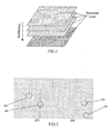
- the optical watermark in this invention has a multiple layered structure as shown in Figure 1. Watermark layers are superposed on each other to provide multiple layers and categories of protection. This superposition of several layers means that it is very difficult, if not impossible, to derive the parameters of the structure and the hidden information from the optical watermark alone.
- Each watermark layer is a repetitive structured array of dots.
- Latent image objects are embedded into the watermark layer by modulation. This may include, for example, phase modulation.
- the structure and orientation of the different watermark layers in an optical watermark must be different from each other. Only the decoder corresponding to a particular watermark layer can be used to view the latent image object embedded in that particular watermark layer.
- the basic watermark layer is a 2-D dot array, varying in two orthogonal directions.
- phase modulation can be applied to both directions. As shown in Figure 2, part 205 is the phase modulation in the horizontal direction to embed a letter "T”, while part 206 shows the phase modulation in the vertical direction to embed a letter "C”.
- the phase modulation changes the distances between a pair of dots at the edge of the latent images in the direction of the phase modulation. According to the characteristics of the human visual system, such changes of distances will make the edge of the latent image become either lighter or darker than the overall grey level of the dot array. Such effect will reveal the shape of the latent images.
- a "smoothing" process may be applied to the regions with an abrupt phase shift. For example, in Figure 2, along regions indicated as 201 and 202, the distance between a pair of dots was greater than the spatial repetitive period of the dot array. Therefore, a dot is added, together with distance adjustment, to make the edge a little darker. Patterns 201 and 202 are the results after compensation. On other hand, when the distance between two dots is much smaller than the repetitive period of the dot array, distance adjustment may also be necessary to make the edge a little lighter. Patterns 203 and 204 are the result of this type of adjustment.
- the decoder should have a grating structure with the same spatial frequency as the dot arrays.
- the orientation of the decoder should be aligned in the same direction.
- Figure 3(01) and Figure 3(02) show the demodulation result of Figure 2. The detailed mathematical analysis is in accordance with a Fourier Series Expansion.
- dot arrays are selected as the carrier dot patterns to embed latent image objects. Because dot arrays can be considered as 2-D signals, which vary in two orthogonal directions, two latent image objects can be modulated to one dot pattern in two directions with phase modulation. For the sake of simplicity, the dot arrays discussed here have the same spatial repetitive frequency in both directions. In an actual optical watermark, the frequencies in the two directions may be different.
- a Fourier series expansion is employed to analyse the modulation and demodulation. Let us denote basic dot pattern as f ⁇ [0,1] f 0 (x, y), where and the value 0 represents black, and 1 represents white. The superposition of line gratings can be represented with the product of functions. This multiplicative model enables analysis with a Fourier series expansion.
- the phase-shifted dot array can be represented as f 1 ( x , y ) and f 2 (x, y), each corresponding to a modulation direction.
- Two latent image objects to be modulated can be represented as g 1 ( x , y ) and g 2 (x, y) . Their valid values can only be either 0 or 1. So the watermarked dot array can be represented as
- the decoders can be represented as In eq. (A.5) the angle ⁇ is the angle between the orientation of f d (x,y) and the direction of y-axis.
- c 1 (1,1) cos 2 ⁇ T [(1 - cos ⁇ ) x + y sin ⁇ ]
- c 2 (1,1) cos 2 ⁇ T [ x cos ⁇ + (1 - sin ⁇ ) y ]
- the mathematical derivation shows that with phase modulation two latent image objects can be modulated to the basic dot pattern. Because of the relatively high frequency of the dot array and the compensation methods applied on the edge, the latent image objects will not be observed by unaided eyes. In order to view the latent image objects, the frequency of the decoder should be the same as the frequency of the basic carrier dot pattern along that direction, and the orientation of the decoder should be aligned to the same direction in which the latent image object is modulated.
- the human visual system has the highest contrast sensitivity in the mid spatial frequency range, around 2-6 c/deg.
- the sensitivity has a sharp drop at high spatial frequencies.
- the human eye is sensitive to relative phase, which is the shift or displacement between spatial signals at same frequency.
- the threshold phase is represented by the displacement of about 0.85' arc.
- the threshold of relative phase is about 5° .
- a human observer will not be able to observe the relative phase, which is less than this threshold. So for high frequency signals, the displacement will not be easily observed by unaided eyes.
- the latent image object in each watermark layer is encoded with relatively high repetitive frequency dot patterns with phase modulation.
- the displacement is not significant to the human visual system because the relative phase difference is lower than, or similar to, the threshold at that relative high frequency, which is selected for the optical watermark. So the latent image objects will not be observed without proper decoders.
- the frequencies of dot arrays along two directions can be different, and the dot arrays may take any orientation.
- the watermark layer is denoted as L ( f u , f v , ⁇ , g u , g v ), where f u and f v are the frequencies of dot array in two directions u and v , respectively, and ⁇ is the angle between u and x (horizontal axis)
- the functions g u and g v whose value can only be 1 or 0, represent the latent image objects in this layer.
- the function representing a watermark layer is:
- each latent image object in this type of watermark layer There are two parameters for each latent image object in this type of watermark layer: one is the modulation frequency and the other is the modulation orientation.
- the parameters for the latent image g u are f u and u . While the parameters for the latent image g v are f v and v . Only a decoder with the corresponding frequency can make a particular latent image visible when it's rotated to the corresponding direction. So the keys to the secrets in this type of watermark layer are the modulation frequency and the modulation orientation.
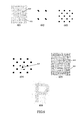
- Figure 401 shows the coordinates of one watermark layer, with reference to a x-y co-ordinate.
- Figure 402, 403 and 404 are three watermark layers, and Figure 405 is their superposition result.
- the optical watermark is the superposition of several watermark layers. Such superposition can be represented as
- Figure 4(05) shows an sample of the optical watermark, which is the superposition of Figure 4(02), Figure 4(03) and Figure 4(04).
- the frequency and the orientation of the decoder are the keys to decode the latent image objects. Only when the frequency of the decoder matches the modulation frequency and orientation of a particular latent image object, will the latent image object appear in the superposition.
- this multiple-layer structure is that all the watermark layers protect each other. Without knowing the details (parameters and latent image objects) of all the watermark layers, it's very difficult, and almost impossible, to change the information in one of the watermark layers. If one of the watermark layers is changed, all other watermark layers will also be affected by this change. Therefore, this change, even it may be authorized by one party, will invalidate the authenticity of the document, in a scenario of a multiple party application, where each party is holding a "key" to a latent image object.
- basic 2-D dot arrays can be generalized to any 2-D pattern, by coordinate mapping and superposition.
- m x (u,v) and m y (u,v) map the coordinate space from (u,v) to (x,y) .
- the modulation and demodulation of the watermark layer are the same as the basic watermark layer.
- the demodulation with a decoder is done in the ( x,y ) coordinate space.
- the decoder in the ( x,y ) coordinate space should be mapped from the corresponding decoder in the ( u,v ) coordinate space.
- the parameters of a latent image object are the modulation frequency of the latent image object in the ( u,v ) coordinate space, the modulation orientation of the latent image object in the ( u,v ) coordinate space, and the mapping functions m x (u,v ) and m y (u,v ) .
- the original decoder In order to demodulate the latent image object embedded in the watermark layer with coordinate system mapping, the original decoder should also be mapped from the (u, v) coordinate system to the (x,y) coordinate system:
- the corresponding decoder is d'(x,y) in eq. (28) but not d 0 (x,y) in eq. (27).
- equation (28) that the key space is expanded by two factors: one is the sine function, and the other is the period of the sine function.
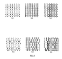
- Figure 501, 502 and 503 are simple watermark layers with/without phase modulation. It is relatively simple to derive parameters from them.
- Figure 504,505 and 506 are watermark layers with random dot patterns. It is very complex, and virtually impossible, to recover latent image object information without decoders.
- the key space of the decoder used to view the embedded latent image object is an indication of the security a watermark method or apparatus may have.
- the key space is very small for the prior art patents listed earlier. It is possible to find the key space with careful analysis or brute force attack from an expert in the area.
- Figure 501, 502 and 503 show regular patterns with and without phase modulation. From the view point of cryptography, the problem of these watermark layers is that the space of the keys is too small. It is obvious that one can easily derive the key parameter by observing the watermark.
- the key space can be expanded by two factors.
- the watermark layer can be further generalised as a random pattern in a 2-D space.
- the amount of information of the latent image object can reach its maximum when it is randomly distributed.
- the randomly distributed information is divided into two parts: the watermark layer is generated based on one part, while the decoder is generated based on the other part.
- both of the watermark layer and the decoder hold the information about the latent image object.
- the latent image is recoverable only when both the watermark layer and the decoder are presented.
- Two functions g w ( x,y ) and g d ( x,y ) can be generated based on the latent image object g ( x,y ) and a random function r ( x,y ), which will return either 0 or 1 at random.
- the function g w ( x , y) is then encoded into the girds of the watermark layer with phase modulation, while the function g d (x,y) is also encoded into the line gratings of the decoder with phase modulation. Note that the value of g w ( x , y ), g d (x,y) and g(x,y) can only be either 1 or 0.
- No information about the latent image object can be found from investigating the function either g d ( x , y ) or g w ( x , y ).
- the watermark layer can be represented as:
- Figures 504, 505 and 506 are examples of the random pattern watermark layers corresponding to Figure 501, Figure 502 and Figure 503.
- a random pattern watermark layer needs accurate alignment to reveal the latent image object.
- the dot pattern of a watermark layer can be the result of a set of operations on one, or a set of basic, and other types of dot patterns.
- the counterfeit-proof layer is an example.
- the counterfeit-proof layer is a special watermark layer where a photocopier is the decoder to the latent image object.
- the dot pattern in the counterfeit-proof watermark layer is based on the superposition of the basic dot arrays.
- the latent image object in this layer which can be some cancelation words such as "COPY”, can be represented as a function g c ( x,y ) .
- the value of this function can only be 0 or 1.
- this layer can be represented as a function w c ( x,y ) .
- the functions f a ( x , y ) and f b ( x , y ) represent two sets of basic dot arrays.
- the repetitive period T a of f a ( x , y ) is slightly larger then the period T b of f b (x,y) .
- the ⁇ in eq. (33) represents a small displacement.
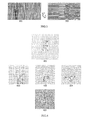
- Figure 601 is a sample of such a counterfeit-proof layer.
- Figure 602 is a enlarged view of the overlapped dot arrays which are represented by f a ( x,y ) f a ( x + ⁇ , y + ⁇ ) .
- Each dot in the dot array f a ( x,y ) will adjoin to a dot in the other dot array f a ( x + ⁇ , y + ⁇ ) because ⁇ is a small enough displacement.
- Figure 603 is an enlarged view of the overlapped dot arrays which are represented with f b ( x,y ) f b ( x + T b / 2, y + T b / 2).
- the dot size in this counterfeit-proof layer should be carefully chosen. It should be smaller than the size of the dot that a photocopier can sample.
- a preferred dot size is 1 / 600 inches, because the optical resolution of most photocopiers is less than 6001pi. Such dots will disappear after photocopying because they are too small to be recognized by the photocopier. As such, the regions where the value of g c ( x,y ) is 1, will fade after photocopying because all dots in these regions are isolated and cannot be sampled by the photocopier. On the other hand, the regions where the value of g c (x,y) is 0, will still remain because adjacent dot pairs are viewed as having a relatively large size, and can be sampled by the photocopier. Hence the latent image object will be able to appear after photocopying.
- Superposition of counterfeit-proof layer with other watermark layers is also operated according to eq. (18).
- the only necessary post-processing is for the region outside the latent image object.
- Figure 6 of relevance here with Figures 602 and 603 representing typical dot patterns in object regions and non-object regions.
- Figure 604 illustrates the post-processing for superposition of a counterfeit-proof layer with other watermark layers.
- Figure 605 is the superposition result
- Figure 606 is the photocopying result of Figure 605.As shown in Figure 604, when a dot 613 of the watermark layer is superposed onto the counterfeit-proof layer, all other dots with a area indicated by the dash line box should be removed.
- optical watermark in document delivery, ardival and authentication.
- the optical watermark can be applied to an electronic document.
- the optical watermark added to the document can be viewed as a seal to provide authenticity to the document.
- the visual apperance of the optical watermark can be disigned as a logo or seal of the authority to provide immediate trust.
- the embedded information can be the name, signature and logo of the authority, or some number or words related to the document content.
- application scenario 1 is an authority such as, for example, an immigration department of a government, which issues passports to citizens.
- the optical watermark is attached to a page of the passport, either as the background or as a seal of the immigration department.
- a photograph of the passport holder is embedded into one layer, and the name and birth date is on the other layers.
- a special symbol is embedded into a random pattern watermark layer.
- Key lenses are distributed to various parties who need to verify the validity of the passport. The random key can be retained by the immigration department for final verification.
- the passport is issued by the immigration department, and the holder may need to be checked by other parties such as passport controller of other countries.
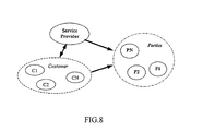
- Figure 8 is a service model.
- a service provider provides delivery and authentication services to customers.
- a customer for example, a shipping company, issues a bill of lading through the service provider to a shipper or consignee.
- An optical watermark having a shape of the carrier's logo, is placed on all non-negotiable bills of lading as background.
- Verification keys are distributed to banks and carrier agents for authentication purposes when the shipper and consignee use the bill of lading to claim the money and cargo.
- the key lenses can be replaced periodically, for example, every 6 months, by the service provider for security reasons.
- optical watermark described above can be readily applied to a document using more than one colour such as, for example, but not limited to, having different watermark layers into different colour channels in various colour spaces. Examples are CMYK and RGB.
Abstract
Description


Claims (25)
- A method for producing an optical watermark on a document, the method including the step of:a) determining a required plural number of watermark layers and a dot pattern for each of the plurality of watermark layers;b) selecting at least one latent image object for each of the plural number of watermark layers and embedding each latent image object into its respective watermark layer;c) superposing the watermark layers to form the watermark;d) defining and generating a decoder for each of the number of watermark layers; ande) applying the optical watermark to the document.
- The method of claim 1, wherein the dot pattern for each of the number of watermark layers is a pattern defined on a two dimensional digital image plane.
- The method of claim 1 or claim 2, wherein the dot pattern is selected from the group consisting a basic two-dimensional dot array; a linear coordinate mapping of a basic two-dimensional dot array; and a random distributed dot array.
- The method of claim 1 or claim 2, wherin the dot pattern also includes a non-linear coordinate mapping of a basic two-dimensional dot array.
- The method of claim 1 or claim 2, wherein the dot pattern is a result of a set of operations on a set of basic and other types of two-dimensional dot arrays.
- The method of any one of claims 1 to 5, wherein the latent image objects contain information which is critical to the application, the information being selected from the group consisting of: copy, void, a critical name, and a number from the document.
- The method of any one of claims 1 to 6, wherein the latent image object is embedded into each watermark layer by a modulation method.
- The method of claim 7, wherein the modulation is phase modulation, the phase modulation including a post-processing to smooth any abrupt phase changes along the edges of the latent image object; and, after modulation, the watermark layer and its decoder each carries part of the information of the latent image object which is generated based on the latent image object and a random function.
- The method of any one of claims 1 to 8, wherein the decoder has a decoder structure related to a dot pattern structure of a carrier dot pattern of the watermark layer and in the direction where the latent image object. is embedded, the relationship being selected from the group consisting of: the same, and conjunct.
- The method of any one of claims 1 to 9, wherein the watermark layers are different to each other and are of sufficient difference to avoid interference between them as a result of them being superposed; one of the watermark layers being a counterfeit-proof layer, the decoder for which is a photocopier; and, after the superposition of the watermark layers with the counterfeit-proof layer, there is included a post-processing step to remove dots which are too close to adjacent dots in a non-object area.
- The method of any one of claims 1 to 10, when included in a method for printing a document for protection and authentication including the steps of:a) verifying the authenticity and copyright of the document before printing;b) generating the optical watermark according to the method of claim 1;c) controlling the printing process to protect the document and the optical watermark from attack; andd) generating the decoder device and distributing the decoder device to enable verification of the authenticity of the document.
- The method of any one of claims 1 to 11, wherein the optical watermark is extended to colour documents, and the watermark layers are in different colour channels in various colour spaces; and wherein colour spaces CMY/CMYK, HIS, XYA, Yuv and RGB are used.
- An optical watermark for use on a document, the optical watermark having:a) a required plural number of watermark layers, each of the plural number of watermark layers each being a dot pattern;b) at least one latent image object embedded into each watermark layer; andc) the watermark layers being superposed to form the optical watermark
- The optical watermark of claim 13, wherein the dot pattern for each of the number of watermark layers is a dot pattern defined on a two dimensional digital image plane.
- The optical watermark of claim 13 or claim 14, wherein the dot pattern is selected from the group consisting of a basic two-dimensional dot array, a linear coordinate mapping of a basic two-dimensional dot array, and a random distributed dot array.
- The optical watermark of any one of of claims 13 to 15, wherin the dot pattern also includes a non-linear coordinate mapping of a basic two-dimensional dot array.
- The optical watermark of any one of claims 13 to 16, wherein the dot pattern is a result of a set of operations on a set of basic and other types of two-dimensional dot arrays.
- The optical watermark of any one of claims 13 to 17, wherein the latent image objects contain information which is critical to the application; the information being selected from the group consisting of: copy, void, a critical name, and a number from the document.
- The optical watermsrk of any one of claims 13 to 18, wherein the latent image object is embedded into each watermark layer by modulation, any abrupt phase changes along the edges of the latent image object being smoothed.
- The optical watermark of any one of claims 13 to 19, wherein there is included a decoder for each watermark layer which has a decoder structure related to a dot pattern structure of a carrier dot pattern of the relevant watermark layer and in the direction where the latent image object is embedded, the relationship being selected from the group consisting of: the same, and conjunct.
- The optical watermark of claim 19, wherein after modulation the watermark layer and its decoder each carries part of the information of the latent image object which is generated based on the latent image object and a random function.
- The optical watermark of any one of claims 13 to 21, wherein the watermark layers are different to each other and are of sufficient difference to avoid interference between them as a result of them being superposed.
- The optical watermark of claim 20, wherein one of the watermark layers is a counterfeit-proof layer, the decoder for which is a photocopier, and after superposition of the watermark. layers with the counterfeit-proof layer, dots which are too close to adjacent dots in a non-object area are removed.
- The optical watermark of any one of claims 13 to 23, included on or in a document for protection and authentication; the watermark being included on or in the document as a device selected from the group consisting of background, seal, logo, graphic device, trade mark and a word.
- The optical watermark of any one of claims 13 to 24, wherein the optical watermark is coloured, the watermark layers being in different colour channels in various colour spaces, colour spaces CMY/CMYK, HIS, XYZ, Yuv and RGB being used.
Applications Claiming Priority (1)
| Application Number | Priority Date | Filing Date | Title |
|---|---|---|---|
| PCT/SG2000/000147 WO2002023481A1 (en) | 2000-09-15 | 2000-09-15 | Optical watermark |
Publications (2)
| Publication Number | Publication Date |
|---|---|
| EP1317734A1 EP1317734A1 (en) | 2003-06-11 |
| EP1317734B1 true EP1317734B1 (en) | 2005-02-16 |
Family
ID=20428862
Family Applications (1)
| Application Number | Title | Priority Date | Filing Date |
|---|---|---|---|
| EP00964869A Expired - Lifetime EP1317734B1 (en) | 2000-09-15 | 2000-09-15 | Optical watermark |
Country Status (8)
| Country | Link |
|---|---|
| US (1) | US7366301B2 (en) |
| EP (1) | EP1317734B1 (en) |
| JP (1) | JP4373045B2 (en) |
| CN (1) | CN1170254C (en) |
| AT (1) | ATE289437T1 (en) |
| AU (1) | AU785178B2 (en) |
| DE (1) | DE60018222T2 (en) |
| WO (1) | WO2002023481A1 (en) |
Families Citing this family (77)
| Publication number | Priority date | Publication date | Assignee | Title |
|---|---|---|---|---|
| US6449377B1 (en) | 1995-05-08 | 2002-09-10 | Digimarc Corporation | Methods and systems for watermark processing of line art images |
| US6763122B1 (en) | 1999-11-05 | 2004-07-13 | Tony Rodriguez | Watermarking an image in color plane separations and detecting such watermarks |
| US20030056103A1 (en) * | 2000-12-18 | 2003-03-20 | Levy Kenneth L. | Audio/video commerce application architectural framework |
| US6993149B2 (en) * | 2001-09-25 | 2006-01-31 | Digimarc Corporation | Embedding digital watermarks in spot colors |
| US7738673B2 (en) | 2000-04-19 | 2010-06-15 | Digimarc Corporation | Low visible digital watermarks |
| US7162035B1 (en) | 2000-05-24 | 2007-01-09 | Tracer Detection Technology Corp. | Authentication method and system |
| AU2002214613A1 (en) * | 2000-11-08 | 2002-05-21 | Digimarc Corporation | Content authentication and recovery using digital watermarks |
| US7072487B2 (en) * | 2001-01-26 | 2006-07-04 | Digimarc Corporation | Watermark detection using adaptive color projections |
| US7039215B2 (en) * | 2001-07-18 | 2006-05-02 | Oki Electric Industry Co., Ltd. | Watermark information embedment device and watermark information detection device |
| US7213757B2 (en) | 2001-08-31 | 2007-05-08 | Digimarc Corporation | Emerging security features for identification documents |
| JP2003174556A (en) * | 2001-09-26 | 2003-06-20 | Canon Inc | Image processing apparatus and image processing method |
| US7321667B2 (en) * | 2002-01-18 | 2008-01-22 | Digimarc Corporation | Data hiding through arrangement of objects |
| US8171567B1 (en) | 2002-09-04 | 2012-05-01 | Tracer Detection Technology Corp. | Authentication method and system |
| US20040179713A1 (en) * | 2003-03-11 | 2004-09-16 | Kenji Tani | Image processing method, image processing apparatus, and information processing apparatus |
| AU2003902810A0 (en) * | 2003-06-04 | 2003-06-26 | Commonwealth Scientific And Industrial Research Organisation | Method of encoding a latent image |
| US7245740B2 (en) * | 2003-07-01 | 2007-07-17 | Oki Electric Industry Co., Ltd. | Electronic watermark embedding device, electronic watermark detection device, electronic watermark embedding method, and electronic watermark detection method |
| CA2529388C (en) | 2003-07-07 | 2013-02-19 | Commonwealth Scientific And Industrial Research Organisation | Method of encoding a latent image |
| US20050021970A1 (en) * | 2003-07-21 | 2005-01-27 | Curtis Reese | Embedded data layers |
| US20050030588A1 (en) * | 2003-08-06 | 2005-02-10 | Curtis Reese | Methods and apparatus utilizing embedded data layers |
| US6980654B2 (en) * | 2003-09-05 | 2005-12-27 | Graphic Security Systems Corporation | System and method for authenticating an article |
| JP2005150815A (en) * | 2003-11-11 | 2005-06-09 | Oki Electric Ind Co Ltd | Watermark information embedding apparatus and method, watermark information detecting apparatus and method, and printed matter |
| US8181884B2 (en) | 2003-11-17 | 2012-05-22 | Digimarc Corporation | Machine-readable features for objects |
| US7114074B2 (en) * | 2003-12-22 | 2006-09-26 | Graphic Security Systems Corporation | Method and system for controlling encoded image production using image signatures |
| EP1547805A1 (en) * | 2003-12-23 | 2005-06-29 | Elca Informatique S.A. | Method for generating and validating tickets printable at home |
| US7551752B2 (en) * | 2004-04-26 | 2009-06-23 | Graphic Security Systems Corporation | Systems and methods for authenticating objects using multiple-level image encoding and decoding |
| US7512249B2 (en) * | 2004-04-26 | 2009-03-31 | Graphic Security Systems Corporation | System and method for decoding digital encoded images |
| WO2005111926A1 (en) * | 2004-05-18 | 2005-11-24 | Silverbrook Research Pty Ltd | Method and apparatus for security document tracking |
| ATE413286T1 (en) * | 2004-06-11 | 2008-11-15 | Ahlstrom Kauttua Oy | LAYERED SAFETY MATERIAL AND PRODUCTION PROCESS THEREOF |
| US9704301B2 (en) * | 2004-08-19 | 2017-07-11 | United States Postal Service | Printed postage container having integrated security features |
| EP1634722B8 (en) * | 2004-09-09 | 2009-10-07 | Alcan Technology & Management Ltd. | Article with forgery-proof printing |
| US8144558B1 (en) * | 2004-09-14 | 2012-03-27 | Doug Carson & Associates, Inc. | Hidden patterns on a data storage medium |
| US20100297027A1 (en) * | 2004-12-20 | 2010-11-25 | Nanolnk, Inc. | Overt authentication features for compositions and objects and methods of fabrication and verification thereof |
| JP4660212B2 (en) * | 2005-01-24 | 2011-03-30 | 株式会社東芝 | Image processing apparatus and image processing method |
| WO2006109259A1 (en) * | 2005-04-13 | 2006-10-19 | Koninklijke Philips Electronics N.V. | Encoding with watermarking prior to phase modulation |
| US8243325B2 (en) * | 2005-07-08 | 2012-08-14 | Xerox Corporation | Method for prepress-time color match verification and correction |
| US7487915B2 (en) * | 2005-09-09 | 2009-02-10 | Graphic Security Systems Corporation | Reflective decoders for use in decoding optically encoded images |
| CN101297320A (en) * | 2005-10-26 | 2008-10-29 | 皇家飞利浦电子股份有限公司 | A method of embedding data in an information signal |
| US7706025B2 (en) * | 2005-10-31 | 2010-04-27 | Xerox Corporation | Moiré-based auto-stereoscopic watermarks |
| CN100364326C (en) | 2005-12-01 | 2008-01-23 | 北京北大方正电子有限公司 | Method and apparatus for embedding and detecting digital watermark in text file |
| EP1966763A4 (en) | 2005-12-05 | 2008-12-31 | Commw Scient Ind Res Org | A method of forming a securitized image |
| US9327538B2 (en) * | 2006-01-05 | 2016-05-03 | Ppg Industries Ohio, Inc. | Bragg diffracting security markers |
| JP4719717B2 (en) | 2006-06-27 | 2011-07-06 | 株式会社リコー | Image processing apparatus, image processing method, and image processing program |
| US7860268B2 (en) * | 2006-12-13 | 2010-12-28 | Graphic Security Systems Corporation | Object authentication using encoded images digitally stored on the object |
| WO2008091768A2 (en) * | 2007-01-22 | 2008-07-31 | Global Crypto Systems | Methods and systems for digital authentication using digitally signed images |
| US20090004231A1 (en) * | 2007-06-30 | 2009-01-01 | Popp Shane M | Pharmaceutical dosage forms fabricated with nanomaterials for quality monitoring |
| DE102008012419A1 (en) † | 2007-10-31 | 2009-05-07 | Bundesdruckerei Gmbh | Polymer composite layer for security and/or valuable documents comprises at least two interlocking polymer layers joined together with a surface printed with a printed layer absorbing in the visible region in and/or on the composite |
| JP5264311B2 (en) * | 2008-06-18 | 2013-08-14 | キヤノン株式会社 | Image processing apparatus, control method, and program |
| CA2737430C (en) * | 2008-09-16 | 2015-03-24 | National Printing Bureau, Incorporated Administrative Agency | Anti-counterfeit printed matter, method of manufacturing the same, and recording medium storing halftone dot data creation software |
| US8199969B2 (en) | 2008-12-17 | 2012-06-12 | Digimarc Corporation | Out of phase digital watermarking in two chrominance directions |
| US9117268B2 (en) | 2008-12-17 | 2015-08-25 | Digimarc Corporation | Out of phase digital watermarking in two chrominance directions |
| US20110135888A1 (en) * | 2009-12-04 | 2011-06-09 | Ppg Industries Ohio, Inc. | Crystalline colloidal array of particles bearing reactive surfactant |
| JP2013518328A (en) * | 2010-01-26 | 2013-05-20 | ナノインク インコーポレーティッド | Moire pattern generated by angular illumination of the surface |
| US8582194B2 (en) | 2010-04-29 | 2013-11-12 | Ppg Industries Ohio, Inc. | Thermally responsive crystalline colloidal arrays |
| US8792674B2 (en) | 2010-10-11 | 2014-07-29 | Graphic Security Systems Corporation | Method for encoding and simultaneously decoding images having multiple color components |
| SG189354A1 (en) | 2010-10-11 | 2013-05-31 | Graphic Security Systems Corp | Method for constructing a composite image incorporating a hidden authentication image |
| US9092872B2 (en) | 2010-10-11 | 2015-07-28 | Graphic Security Systems Corporation | System and method for creating an animation from a plurality of latent images encoded into a visible image |
| US20140284382A1 (en) * | 2010-10-26 | 2014-09-25 | Kwang-Don Park | Random-type multilayer identification, and system using same |
| US8490546B2 (en) * | 2010-11-01 | 2013-07-23 | Ppg Industries Ohio, Inc. | Method of imaging in crystalline colloidal arrays |
| US9022648B2 (en) | 2010-11-11 | 2015-05-05 | Prc-Desoto International, Inc. | Temperature sensitive composite for photonic crystals |
| CN102122384B (en) * | 2011-01-25 | 2012-08-15 | 机密科技公司 | Method for manufacturing hidden pattern during plate making for presswork |
| MX2013009995A (en) * | 2011-03-01 | 2013-12-06 | Graphic Security Systems Corp | A method for encoding and simultaneously decoding images having multiple color components. |
| US11210495B2 (en) | 2011-03-17 | 2021-12-28 | New York University | Systems, methods and computer-accessible mediums for authentication and verification of physical objects |
| US9111340B2 (en) | 2011-05-27 | 2015-08-18 | Cisco Technology Inc. | Frequency-modulated watermarking |
| US8641933B2 (en) | 2011-09-23 | 2014-02-04 | Ppg Industries Ohio, Inc | Composite crystal colloidal array with photochromic member |
| US20130077169A1 (en) | 2011-09-23 | 2013-03-28 | Ppg Industries Ohio, Inc. | Hollow particle crystalline colloidal arrays |
| CN103448402B (en) * | 2012-05-28 | 2016-06-22 | 广州市人民印刷厂股份有限公司 | Unlocking anti-fake method |
| WO2013179249A1 (en) * | 2012-05-30 | 2013-12-05 | Label Tech International Trims Limited | Authentication apparatus and methods |
| CN103065101A (en) * | 2012-12-14 | 2013-04-24 | 北京思特奇信息技术股份有限公司 | Anti-counterfeiting method for documents |
| CN104228380B (en) * | 2013-06-21 | 2016-12-28 | 广州市人民印刷厂股份有限公司 | Invisible open locking-type method for anti-counterfeit |
| US9374497B2 (en) | 2014-10-20 | 2016-06-21 | Caterpillar Inc. | Component and watermark formed by additive manufacturing |
| US10826900B1 (en) * | 2014-12-31 | 2020-11-03 | Morphotrust Usa, Llc | Machine-readable verification of digital identifications |
| US9937656B2 (en) | 2016-07-07 | 2018-04-10 | Caterpillar Inc. | Method for printing component with anti-counterfeit features |
| CN109040761A (en) * | 2018-09-17 | 2018-12-18 | 俞群爱 | A kind of monitoring on-wall system with encrypted watermark |
| EP3686027B1 (en) | 2019-01-27 | 2021-07-14 | U-NICA Systems AG | Method of printing authentication indicators with an amplitude-modulated half tone |
| CN113630606B (en) * | 2020-05-07 | 2024-04-19 | 百度在线网络技术(北京)有限公司 | Video watermark processing method, video watermark processing device, electronic equipment and storage medium |
| JP2023003627A (en) * | 2021-06-24 | 2023-01-17 | シヤチハタ株式会社 | Computer device, method, and computer program |
| CN115330583A (en) * | 2022-09-19 | 2022-11-11 | 景德镇陶瓷大学 | Watermark model training method and device based on CMYK image |
Family Cites Families (22)
| Publication number | Priority date | Publication date | Assignee | Title |
|---|---|---|---|---|
| CN85100700A (en) | 1985-04-01 | 1987-01-31 | 陆伯祥 | Computing machine Moire fringe certificate and recognition system thereof |
| US4838644A (en) * | 1987-09-15 | 1989-06-13 | The United States Of America As Represented By The United States Department Of Energy | Position, rotation, and intensity invariant recognizing method |
| US5396559A (en) * | 1990-08-24 | 1995-03-07 | Mcgrew; Stephen P. | Anticounterfeiting method and device utilizing holograms and pseudorandom dot patterns |
| US6000728A (en) | 1991-07-12 | 1999-12-14 | The Standard Register Company | Security document |
| US6345104B1 (en) * | 1994-03-17 | 2002-02-05 | Digimarc Corporation | Digital watermarks and methods for security documents |
| US5659613A (en) * | 1994-06-29 | 1997-08-19 | Macrovision Corporation | Method and apparatus for copy protection for various recording media using a video finger print |
| US6577746B1 (en) * | 1999-12-28 | 2003-06-10 | Digimarc Corporation | Watermark-based object linking and embedding |
| US5767889A (en) * | 1995-08-23 | 1998-06-16 | Intermec Corporation | Bar shaving of the resident fonts in an on-demand barcode printer |
| US5995638A (en) * | 1995-08-28 | 1999-11-30 | Ecole Polytechnique Federale De Lausanne | Methods and apparatus for authentication of documents by using the intensity profile of moire patterns |
| US5708717A (en) | 1995-11-29 | 1998-01-13 | Alasia; Alfred | Digital anti-counterfeiting software method and apparatus |
| US5734752A (en) | 1996-09-24 | 1998-03-31 | Xerox Corporation | Digital watermarking using stochastic screen patterns |
| US5915027A (en) | 1996-11-05 | 1999-06-22 | Nec Research Institute | Digital watermarking |
| US5790703A (en) | 1997-01-21 | 1998-08-04 | Xerox Corporation | Digital watermarking using conjugate halftone screens |
| US5951055A (en) | 1997-06-11 | 1999-09-14 | The Standard Register Company | Security document containing encoded data block |
| EP0921675B1 (en) * | 1997-12-03 | 2006-07-05 | Kabushiki Kaisha Toshiba | Method of processing image information and method of preventing forgery of certificates or the like |
| US6104812A (en) | 1998-01-12 | 2000-08-15 | Juratrade, Limited | Anti-counterfeiting method and apparatus using digital screening |
| US6145081A (en) * | 1998-02-02 | 2000-11-07 | Verance Corporation | Method and apparatus for preventing removal of embedded information in cover signals |
| US6252971B1 (en) * | 1998-04-29 | 2001-06-26 | Xerox Corporation | Digital watermarking using phase-shifted stoclustic screens |
| US6748533B1 (en) * | 1998-12-23 | 2004-06-08 | Kent Ridge Digital Labs | Method and apparatus for protecting the legitimacy of an article |
| US6456726B1 (en) * | 1999-10-26 | 2002-09-24 | Matsushita Electric Industrial Co., Ltd. | Methods and apparatus for multi-layer data hiding |
| US6636616B1 (en) * | 1999-11-30 | 2003-10-21 | Xerox Corporation | Method and apparatus for digital watermarking using error diffusion |
| US6879652B1 (en) * | 2000-07-14 | 2005-04-12 | Nielsen Media Research, Inc. | Method for encoding an input signal |
-
2000
- 2000-09-15 JP JP2001549269A patent/JP4373045B2/en not_active Expired - Fee Related
- 2000-09-15 WO PCT/SG2000/000147 patent/WO2002023481A1/en not_active Application Discontinuation
- 2000-09-15 AT AT00964869T patent/ATE289437T1/en not_active IP Right Cessation
- 2000-09-15 CN CNB008020361A patent/CN1170254C/en not_active Expired - Fee Related
- 2000-09-15 AU AU75690/00A patent/AU785178B2/en not_active Ceased
- 2000-09-15 EP EP00964869A patent/EP1317734B1/en not_active Expired - Lifetime
- 2000-09-15 DE DE60018222T patent/DE60018222T2/en not_active Expired - Lifetime
-
2001
- 2001-03-16 US US09/810,971 patent/US7366301B2/en not_active Expired - Fee Related
Also Published As
| Publication number | Publication date |
|---|---|
| AU7569000A (en) | 2002-03-26 |
| EP1317734A1 (en) | 2003-06-11 |
| AU785178B2 (en) | 2006-10-12 |
| WO2002023481A1 (en) | 2002-03-21 |
| ATE289437T1 (en) | 2005-03-15 |
| US20020054680A1 (en) | 2002-05-09 |
| JP2003530737A (en) | 2003-10-14 |
| US7366301B2 (en) | 2008-04-29 |
| CN1170254C (en) | 2004-10-06 |
| JP4373045B2 (en) | 2009-11-25 |
| DE60018222T2 (en) | 2006-01-12 |
| DE60018222D1 (en) | 2005-03-24 |
| CN1372677A (en) | 2002-10-02 |
Similar Documents
| Publication | Publication Date | Title |
|---|---|---|
| EP1317734B1 (en) | Optical watermark | |
| EP1591953B1 (en) | System and method for decoding digital encoded images | |
| EP1229725B1 (en) | System and method for generating color digital watermarks using conjugate halftone screens | |
| US5790703A (en) | Digital watermarking using conjugate halftone screens | |
| EP0953939B1 (en) | Digital watermarking using phase-shifted stoclustic screens | |
| EP1173001A2 (en) | Authenticatable image with an embedded image having a discernible physical characteristic | |
| Huang et al. | Optical watermarking for printed document authentication | |
| EP1554700B1 (en) | Authentication of documents and articles by moire patterns | |
| US5734752A (en) | Digital watermarking using stochastic screen patterns | |
| EP1554699B1 (en) | Authentication of documents and valuable articles by using moire intensity profiles | |
| EP1286531B1 (en) | Authenticatable image with an embedded image having a discernible physical characteristic with improved security feature | |
| EP2183118A1 (en) | Single-color screen patterns for copy protection | |
| WO2008023691A1 (en) | Printed matter, image processing device, printed matter true/false judging device, image processing method, printed matter true/false determinating method and program | |
| Sun et al. | An optical watermarking solution for authenticating printed documents | |
| Khan et al. | Increased PSNR with improved DWT digital watermarking technique | |
| KR20030005347A (en) | Optical Watermark | |
| Mahmoud | Low Resolution Watermarking for Print Security | |
| KR20060079393A (en) | Visible anti-copy pattern |
Legal Events
| Date | Code | Title | Description |
|---|---|---|---|
| PUAI | Public reference made under article 153(3) epc to a published international application that has entered the european phase |
Free format text: ORIGINAL CODE: 0009012 |
|
| 17P | Request for examination filed |
Effective date: 20020904 |
|
| AK | Designated contracting states |
Designated state(s): AT BE CH CY DE DK ES FI FR GB GR IE IT LI LU MC NL PT SE |
|
| AX | Request for extension of the european patent |
Extension state: AL LT LV MK RO SI |
|
| 17Q | First examination report despatched |
Effective date: 20031008 |
|
| GRAP | Despatch of communication of intention to grant a patent |
Free format text: ORIGINAL CODE: EPIDOSNIGR1 |
|
| GRAS | Grant fee paid |
Free format text: ORIGINAL CODE: EPIDOSNIGR3 |
|
| GRAA | (expected) grant |
Free format text: ORIGINAL CODE: 0009210 |
|
| AK | Designated contracting states |
Kind code of ref document: B1 Designated state(s): AT BE CH CY DE DK ES FI FR GB GR IE IT LI LU MC NL PT SE |
|
| PG25 | Lapsed in a contracting state [announced via postgrant information from national office to epo] |
Ref country code: IT Free format text: LAPSE BECAUSE OF FAILURE TO SUBMIT A TRANSLATION OF THE DESCRIPTION OR TO PAY THE FEE WITHIN THE PRESCRIBED TIME-LIMIT;WARNING: LAPSES OF ITALIAN PATENTS WITH EFFECTIVE DATE BEFORE 2007 MAY HAVE OCCURRED AT ANY TIME BEFORE 2007. THE CORRECT EFFECTIVE DATE MAY BE DIFFERENT FROM THE ONE RECORDED. Effective date: 20050216 Ref country code: NL Free format text: LAPSE BECAUSE OF FAILURE TO SUBMIT A TRANSLATION OF THE DESCRIPTION OR TO PAY THE FEE WITHIN THE PRESCRIBED TIME-LIMIT Effective date: 20050216 Ref country code: BE Free format text: LAPSE BECAUSE OF FAILURE TO SUBMIT A TRANSLATION OF THE DESCRIPTION OR TO PAY THE FEE WITHIN THE PRESCRIBED TIME-LIMIT Effective date: 20050216 Ref country code: AT Free format text: LAPSE BECAUSE OF FAILURE TO SUBMIT A TRANSLATION OF THE DESCRIPTION OR TO PAY THE FEE WITHIN THE PRESCRIBED TIME-LIMIT Effective date: 20050216 Ref country code: FI Free format text: LAPSE BECAUSE OF FAILURE TO SUBMIT A TRANSLATION OF THE DESCRIPTION OR TO PAY THE FEE WITHIN THE PRESCRIBED TIME-LIMIT Effective date: 20050216 |
|
| REG | Reference to a national code |
Ref country code: GB Ref legal event code: FG4D |
|
| REG | Reference to a national code |
Ref country code: CH Ref legal event code: EP |
|
| REG | Reference to a national code |
Ref country code: IE Ref legal event code: FG4D |
|
| REF | Corresponds to: |
Ref document number: 60018222 Country of ref document: DE Date of ref document: 20050324 Kind code of ref document: P |
|
| PG25 | Lapsed in a contracting state [announced via postgrant information from national office to epo] |
Ref country code: GR Free format text: LAPSE BECAUSE OF FAILURE TO SUBMIT A TRANSLATION OF THE DESCRIPTION OR TO PAY THE FEE WITHIN THE PRESCRIBED TIME-LIMIT Effective date: 20050516 Ref country code: DK Free format text: LAPSE BECAUSE OF FAILURE TO SUBMIT A TRANSLATION OF THE DESCRIPTION OR TO PAY THE FEE WITHIN THE PRESCRIBED TIME-LIMIT Effective date: 20050516 Ref country code: SE Free format text: LAPSE BECAUSE OF FAILURE TO SUBMIT A TRANSLATION OF THE DESCRIPTION OR TO PAY THE FEE WITHIN THE PRESCRIBED TIME-LIMIT Effective date: 20050516 |
|
| PG25 | Lapsed in a contracting state [announced via postgrant information from national office to epo] |
Ref country code: ES Free format text: LAPSE BECAUSE OF FAILURE TO SUBMIT A TRANSLATION OF THE DESCRIPTION OR TO PAY THE FEE WITHIN THE PRESCRIBED TIME-LIMIT Effective date: 20050527 |
|
| REG | Reference to a national code |
Ref country code: CH Ref legal event code: NV Representative=s name: A. BRAUN, BRAUN, HERITIER, ESCHMANN AG PATENTANWAE |
|
| NLV1 | Nl: lapsed or annulled due to failure to fulfill the requirements of art. 29p and 29m of the patents act | ||
| PG25 | Lapsed in a contracting state [announced via postgrant information from national office to epo] |
Ref country code: PT Free format text: LAPSE BECAUSE OF FAILURE TO SUBMIT A TRANSLATION OF THE DESCRIPTION OR TO PAY THE FEE WITHIN THE PRESCRIBED TIME-LIMIT Effective date: 20050804 |
|
| PG25 | Lapsed in a contracting state [announced via postgrant information from national office to epo] |
Ref country code: IE Free format text: LAPSE BECAUSE OF NON-PAYMENT OF DUE FEES Effective date: 20050915 Ref country code: CY Free format text: LAPSE BECAUSE OF FAILURE TO SUBMIT A TRANSLATION OF THE DESCRIPTION OR TO PAY THE FEE WITHIN THE PRESCRIBED TIME-LIMIT Effective date: 20050915 |
|
| PG25 | Lapsed in a contracting state [announced via postgrant information from national office to epo] |
Ref country code: LU Free format text: LAPSE BECAUSE OF NON-PAYMENT OF DUE FEES Effective date: 20050930 Ref country code: MC Free format text: LAPSE BECAUSE OF NON-PAYMENT OF DUE FEES Effective date: 20050930 |
|
| PLBE | No opposition filed within time limit |
Free format text: ORIGINAL CODE: 0009261 |
|
| STAA | Information on the status of an ep patent application or granted ep patent |
Free format text: STATUS: NO OPPOSITION FILED WITHIN TIME LIMIT |
|
| 26N | No opposition filed |
Effective date: 20051117 |
|
| ET | Fr: translation filed | ||
| REG | Reference to a national code |
Ref country code: IE Ref legal event code: MM4A |
|
| REG | Reference to a national code |
Ref country code: CH Ref legal event code: PFA Owner name: TRUSTCOPY PTE LTD Free format text: TRUSTCOPY PTE LTD#C/O KENT RIDGE DIGITAL LABS, 21 HENG MUI KENG TERRACE#SINGAPORE 119631 (SG) -TRANSFER TO- TRUSTCOPY PTE LTD#C/O KENT RIDGE DIGITAL LABS, 21 HENG MUI KENG TERRACE#SINGAPORE 119631 (SG) |
|
| REG | Reference to a national code |
Ref country code: CH Ref legal event code: PCAR Free format text: NEW ADDRESS: HOLBEINSTRASSE 36-38, 4051 BASEL (CH) |
|
| REG | Reference to a national code |
Ref country code: FR Ref legal event code: PLFP Year of fee payment: 17 |
|
| PGFP | Annual fee paid to national office [announced via postgrant information from national office to epo] |
Ref country code: GB Payment date: 20160927 Year of fee payment: 17 Ref country code: CH Payment date: 20160927 Year of fee payment: 17 |
|
| PGFP | Annual fee paid to national office [announced via postgrant information from national office to epo] |
Ref country code: FR Payment date: 20160926 Year of fee payment: 17 |
|
| PGFP | Annual fee paid to national office [announced via postgrant information from national office to epo] |
Ref country code: DE Payment date: 20160928 Year of fee payment: 17 |
|
| REG | Reference to a national code |
Ref country code: DE Ref legal event code: R119 Ref document number: 60018222 Country of ref document: DE |
|
| REG | Reference to a national code |
Ref country code: CH Ref legal event code: PL |
|
| GBPC | Gb: european patent ceased through non-payment of renewal fee |
Effective date: 20170915 |
|
| REG | Reference to a national code |
Ref country code: FR Ref legal event code: ST Effective date: 20180531 |
|
| PG25 | Lapsed in a contracting state [announced via postgrant information from national office to epo] |
Ref country code: GB Free format text: LAPSE BECAUSE OF NON-PAYMENT OF DUE FEES Effective date: 20170915 Ref country code: CH Free format text: LAPSE BECAUSE OF NON-PAYMENT OF DUE FEES Effective date: 20170930 Ref country code: LI Free format text: LAPSE BECAUSE OF NON-PAYMENT OF DUE FEES Effective date: 20170930 Ref country code: DE Free format text: LAPSE BECAUSE OF NON-PAYMENT OF DUE FEES Effective date: 20180404 |
|
| PG25 | Lapsed in a contracting state [announced via postgrant information from national office to epo] |
Ref country code: FR Free format text: LAPSE BECAUSE OF NON-PAYMENT OF DUE FEES Effective date: 20171002 |