EP1309149B1 - System and method for improving communication between a public switched telephone network and a packet network - Google Patents
System and method for improving communication between a public switched telephone network and a packet network Download PDFInfo
- Publication number
- EP1309149B1 EP1309149B1 EP02024349A EP02024349A EP1309149B1 EP 1309149 B1 EP1309149 B1 EP 1309149B1 EP 02024349 A EP02024349 A EP 02024349A EP 02024349 A EP02024349 A EP 02024349A EP 1309149 B1 EP1309149 B1 EP 1309149B1
- Authority
- EP
- European Patent Office
- Prior art keywords
- user agent
- router
- media
- session
- address
- Prior art date
- Legal status (The legal status is an assumption and is not a legal conclusion. Google has not performed a legal analysis and makes no representation as to the accuracy of the status listed.)
- Expired - Lifetime
Links
Images


Classifications
-
- H—ELECTRICITY
- H04—ELECTRIC COMMUNICATION TECHNIQUE
- H04L—TRANSMISSION OF DIGITAL INFORMATION, e.g. TELEGRAPHIC COMMUNICATION
- H04L12/00—Data switching networks
- H04L12/64—Hybrid switching systems
- H04L12/6418—Hybrid transport
-
- H—ELECTRICITY
- H04—ELECTRIC COMMUNICATION TECHNIQUE
- H04L—TRANSMISSION OF DIGITAL INFORMATION, e.g. TELEGRAPHIC COMMUNICATION
- H04L12/00—Data switching networks
- H04L12/66—Arrangements for connecting between networks having differing types of switching systems, e.g. gateways
-
- H—ELECTRICITY
- H04—ELECTRIC COMMUNICATION TECHNIQUE
- H04L—TRANSMISSION OF DIGITAL INFORMATION, e.g. TELEGRAPHIC COMMUNICATION
- H04L45/00—Routing or path finding of packets in data switching networks
-
- H—ELECTRICITY
- H04—ELECTRIC COMMUNICATION TECHNIQUE
- H04L—TRANSMISSION OF DIGITAL INFORMATION, e.g. TELEGRAPHIC COMMUNICATION
- H04L45/00—Routing or path finding of packets in data switching networks
- H04L45/42—Centralised routing
-
- H—ELECTRICITY
- H04—ELECTRIC COMMUNICATION TECHNIQUE
- H04L—TRANSMISSION OF DIGITAL INFORMATION, e.g. TELEGRAPHIC COMMUNICATION
- H04L65/00—Network arrangements, protocols or services for supporting real-time applications in data packet communication
- H04L65/10—Architectures or entities
- H04L65/102—Gateways
- H04L65/1043—Gateway controllers, e.g. media gateway control protocol [MGCP] controllers
-
- H—ELECTRICITY
- H04—ELECTRIC COMMUNICATION TECHNIQUE
- H04L—TRANSMISSION OF DIGITAL INFORMATION, e.g. TELEGRAPHIC COMMUNICATION
- H04L65/00—Network arrangements, protocols or services for supporting real-time applications in data packet communication
- H04L65/1066—Session management
- H04L65/1101—Session protocols
- H04L65/1104—Session initiation protocol [SIP]
-
- H—ELECTRICITY
- H04—ELECTRIC COMMUNICATION TECHNIQUE
- H04L—TRANSMISSION OF DIGITAL INFORMATION, e.g. TELEGRAPHIC COMMUNICATION
- H04L65/00—Network arrangements, protocols or services for supporting real-time applications in data packet communication
- H04L65/60—Network streaming of media packets
- H04L65/65—Network streaming protocols, e.g. real-time transport protocol [RTP] or real-time control protocol [RTCP]
-
- H—ELECTRICITY
- H04—ELECTRIC COMMUNICATION TECHNIQUE
- H04L—TRANSMISSION OF DIGITAL INFORMATION, e.g. TELEGRAPHIC COMMUNICATION
- H04L65/00—Network arrangements, protocols or services for supporting real-time applications in data packet communication
- H04L65/60—Network streaming of media packets
- H04L65/75—Media network packet handling
- H04L65/765—Media network packet handling intermediate
-
- H—ELECTRICITY
- H04—ELECTRIC COMMUNICATION TECHNIQUE
- H04L—TRANSMISSION OF DIGITAL INFORMATION, e.g. TELEGRAPHIC COMMUNICATION
- H04L67/00—Network arrangements or protocols for supporting network services or applications
- H04L67/14—Session management
-
- H—ELECTRICITY
- H04—ELECTRIC COMMUNICATION TECHNIQUE
- H04L—TRANSMISSION OF DIGITAL INFORMATION, e.g. TELEGRAPHIC COMMUNICATION
- H04L69/00—Network arrangements, protocols or services independent of the application payload and not provided for in the other groups of this subclass
- H04L69/08—Protocols for interworking; Protocol conversion
-
- H—ELECTRICITY
- H04—ELECTRIC COMMUNICATION TECHNIQUE
- H04L—TRANSMISSION OF DIGITAL INFORMATION, e.g. TELEGRAPHIC COMMUNICATION
- H04L69/00—Network arrangements, protocols or services independent of the application payload and not provided for in the other groups of this subclass
- H04L69/18—Multiprotocol handlers, e.g. single devices capable of handling multiple protocols
-
- H—ELECTRICITY
- H04—ELECTRIC COMMUNICATION TECHNIQUE
- H04M—TELEPHONIC COMMUNICATION
- H04M7/00—Arrangements for interconnection between switching centres
- H04M7/12—Arrangements for interconnection between switching centres for working between exchanges having different types of switching equipment, e.g. power-driven and step by step or decimal and non-decimal
- H04M7/1205—Arrangements for interconnection between switching centres for working between exchanges having different types of switching equipment, e.g. power-driven and step by step or decimal and non-decimal where the types of switching equipement comprises PSTN/ISDN equipment and switching equipment of networks other than PSTN/ISDN, e.g. Internet Protocol networks
- H04M7/1225—Details of core network interconnection arrangements
-
- H—ELECTRICITY
- H04—ELECTRIC COMMUNICATION TECHNIQUE
- H04M—TELEPHONIC COMMUNICATION
- H04M7/00—Arrangements for interconnection between switching centres
- H04M7/12—Arrangements for interconnection between switching centres for working between exchanges having different types of switching equipment, e.g. power-driven and step by step or decimal and non-decimal
- H04M7/1205—Arrangements for interconnection between switching centres for working between exchanges having different types of switching equipment, e.g. power-driven and step by step or decimal and non-decimal where the types of switching equipement comprises PSTN/ISDN equipment and switching equipment of networks other than PSTN/ISDN, e.g. Internet Protocol networks
- H04M7/1285—Details of finding and selecting a gateway for a particular call
-
- H—ELECTRICITY
- H04—ELECTRIC COMMUNICATION TECHNIQUE
- H04L—TRANSMISSION OF DIGITAL INFORMATION, e.g. TELEGRAPHIC COMMUNICATION
- H04L12/00—Data switching networks
- H04L12/64—Hybrid switching systems
- H04L12/6418—Hybrid transport
- H04L2012/6472—Internet
-
- H—ELECTRICITY
- H04—ELECTRIC COMMUNICATION TECHNIQUE
- H04L—TRANSMISSION OF DIGITAL INFORMATION, e.g. TELEGRAPHIC COMMUNICATION
- H04L12/00—Data switching networks
- H04L12/64—Hybrid switching systems
- H04L12/6418—Hybrid transport
- H04L2012/6475—N-ISDN, Public Switched Telephone Network [PSTN]
-
- H—ELECTRICITY
- H04—ELECTRIC COMMUNICATION TECHNIQUE
- H04L—TRANSMISSION OF DIGITAL INFORMATION, e.g. TELEGRAPHIC COMMUNICATION
- H04L12/00—Data switching networks
- H04L12/64—Hybrid switching systems
- H04L12/6418—Hybrid transport
- H04L2012/6486—Signalling Protocols
Definitions
- the present invention generally relates to telecommunications and, more particularly, is related to a system and method for improving communication between a switched network and a packet network.
- PSTN public switched telephone network
- IP Internet protocol
- IP messages are routed or forwarded from one link to the next (i . e ., from a source of a data flow to a destination of the data flow).
- IP packet contains an IP address, which, in Internet protocol version 4 (IPv4), for example, has 32 bits.
- IPv4 Internet protocol version 4
- Each IP address also has a certain number of bits dedicated to a network portion and a certain number of bits dedicated to a host portion.
- IP routers are used to take a data packet from one network (or link) and place it onto another network (or link). Tables are located within IP routers that contain information or criteria used to determine a best way to route the data packet. An example of this information may be the state of network links and programmed distance indications.
- IP routers By using intelligent devices on both sides of a network domain, it is possible to allocate a temporary address to route a packet through a network and restore the original address on the far side of the network when the packet leaves the network. This is the basis for many current virtual private network (VPN) products and is understood in the art.
- VPN virtual private network
- signaling systems are used to provide this information.
- signaling systems used are either signaling system number 7 (SS7) or are equivalent to SS7.
- SS7 network is separate from a voice network and is used for the purpose of switching data messages pertaining to the business of connecting telephone calls and maintaining the signaling network.
- SS7 digital signaling standard is utilized to interface the PSTN to the IP world.
- SS7 utilizes a message structure wherein messages travel from one network entity to another, independent of the actual voice and data to which the messages pertain.
- This message structure utilizes an envelope, referred to as a packet, for traversing messages.
- a gateway is used to facilitate a multimedia packet flow between a packet data network and a PSTN.
- multimedia comprises voice, data, and/or discrete media.
- Gateways are installed at edges between data networks and voice networks, wherein the gateways are used to convert multimedia (and signaling) to ensure communication.
- the media gateway converts multimedia provided in one type of network to the format required in another type of network. For example, a media gateway could terminate bearer channels from a switched circuit network and media streams from a packet network (e.g., real time protocol (RTP) streams in an IP network).
- RTP real time protocol
- a media gateway may be capable of processing audio, video and T.120, alone or in any combination, and is capable of full duplex media translations.
- the media gateway may also play audio/video messages and perform other interactive voice response (IVR) functions, or may perform media conferencing.
- IVR interactive voice response
- SIP Session initiation protocol
- SIP Session initiation protocol
- softswitches have a virtual connection to other softswitches for completing calls.
- Softswitches otherwise referred to as call agents or media gateway controllers, manage the gateways located within a network.
- the softswitch may use a media gateway control protocol to communicate with the gateways.
- the media gateway control protocol runs between the softswitch and the gateways in a packet telephony network.
- softswitches control the part of a call state that pertains to connection control for media channels in a media gateway.
- Gateways are expected to execute commands sent by the softswitches via use of the media gateway control protocol. Typically, these commands include the translation between audio signals and the packet network.
- these commands include the translation between audio signals and the packet network.
- policy management issues include assuring that each softswitch knows the IP address of each other softswitch and what telephone numbers or PSTN to which they connect.
- the present invention generally relates to systems and methods for improving communication between a public switched network and a packet network.
- the system utilizes a signaling gateway for converting signaling in a first protocol into a second protocol, and from the second protocol to the first protocol.
- At least one media gateway is utilized for converting multimedia provided in a first format into a second format, and from the second format into the first format.
- a session router is utilized for selecting at least one multimedia transmission route to a destination, wherein the destination is specified by the switched network and is located within the packet network.
- a media router is also utilized by the communication system for guiding the multimedia to the destination after conversion by the media gateway.
- the present invention can also be viewed as providing one or more methods for establishing a call from a switched network to a user agent, wherein the user agent is located within a packet network.
- one such method can be broadly summarized by the following steps: transmitting an initial address message from the switched network to a signaling gateway; converting with the signaling gateway the initial address message to a session Internet protocol invite message; transmitting the Internet protocol invite message to a session router, which analyzes the Internet protocol invite message to determine a best route to the user agent; and opening a media router address and port, within a media router, for multimedia transmission from the user agent to said switched network, as a result of a request from said session router, wherein the media router is capable of guiding the multimedia to the user agent.
- FIG. 1 is a block diagram of a prior art communication network.
- FIG. 2 is a block diagram illustrating an improved communication network in accordance with the preferred embodiment of the invention.
- FIG. 3 is a block diagram further illustrating a media router utilized within the improved communication network of FIG. 2 .
- FIG. 4A is a flow chart providing a sequential call flow illustrating a PSTN initiated call setup and execution.
- FIG. 4B is a continuation of FIG. 4A .
- FIG. 4C is a continuation of FIG. 4B .
- FIG. 5 is a block diagram further illustrating the call sequence described by the flow charts of FIGS. 4A , 4B and 4C .
- FIG. 6 is a flow chart providing a sequential call flow illustrating a call tear-down between the PSTN and the user agent of FIG. 2 , that is initiated by the user agent.
- FIG. 7 is a block diagram further illustrating the call sequence described by the flow chart of FIG. 6 .
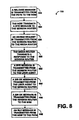
- FIG. 8 is a flow chart providing a sequential call flow illustrating a call tear-down between the PSTN and the user agent of FIG. 2 , that is initiated by the PSTN.
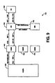
- FIG. 9 is a block diagram further illustrating the call sequence described by the flow chart of FIG. 8 .
- FIG. 10 is a flow chart providing a sequential call flow illustrating a call tear-down between the PSTN and the user agent of FIG. 2 , that is initiated by the media router of FIG. 3 .
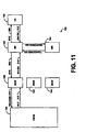
- FIG. 11 is a block diagram further illustrating the call sequence described by the flow chart of FIG. 10 .
- FIG. 12A is a flow chart providing a sequential call flow illustrating a user agent initiated call setup and execution.
- FIG. 12B is a continuation of FIG. 12A .
- FIG. 12C is a continuation of FIG. 12B .
- FIG. 13A is a block diagram further illustrating the call sequence described by the flow chart of FIG. 12A .
- FIG. 13B is a block diagram further illustrating the call sequence described by the flow chart of FIG. 12B and the flow chart of FIG. 12C .
- FIG. 1 is a block diagram illustrating a prior art communication network 102.
- the prior art communication network 102 comprises a PSTN 112, located within a time division multiplexing (TDM) network 121, that is in communication with a user agent 126 located within an IP network 122, as is further described hereinbelow.
- TDM time division multiplexing
- IP network 122 may instead be any packet data network.
- the PSTN 112 segments signaling data and voice on the network 102, thereby allowing for performance guarantees of different traffic components to be set independently.
- a first and second media gateway 114, 116 are utilized by the prior art communication network 102. It should be noted that the number of media gateways may be less or more in accordance with the requirements of the communication network utilizing the gateways.
- the first media gateway 114 and the second media gateway 116 are connected to the PSTN 112 via a transmission channel.
- each individual channel that connects the PSTN 112 to a separate media gateway 114, 116 has a circuit identification code (CIC).
- CIC is used between signaling points to uniquely identify a particular circuit within a network.
- the CIC indicates a trunk circuit reserved by the originating switch (PSTN) to carry a call to a specific RTP port within the network 102.
- the media gateways 114, 116 convert multimedia provided in one type of network to the format used in another type of network. Specifically, media gateways 114, 116 perform multimedia mapping and/or transcoding functions between potentially dissimilar networks, one of which is presumed to be a packet, frame or cell network. For example, specific to the illustrated prior art communication network 102, the media gateways 114, 116 convert media from time division multiplexing (TDM) format used by the PSTN 112 in the TDM network 121, to RTP format in the IP network 122. In accordance with the prior art, the media gateways 114, 116 are typically also responsible for determining the destination of received multimedia.
- TDM time division multiplexing
- a signaling gateway (SGW) 118 is located within the network 102, which is connected to the PSTN 112 via at least one channel.
- SS7 signaling is utilized by the PSTN 112 for the communication of signaling messages between the PSTN 112 and the SGW 118.
- the SGW 118 acts as a signaling agent that receives/sends switched circuit network (SCN) native signaling at the edge of the IP network 122.
- SCN switched circuit network
- the SGW 118 may relay, translate or terminate SS7 signaling.
- the SGW 118 will convert SS7 signaling to SIP signaling, wherein SIP is prevalent in a packet-based network.
- SS7 signaling utilizes a message structure wherein messages travel from one network entity to another, independent of the actual voice and data to which they pertain. This message structure utilizes an envelope, referred to as a packet, for traversing the messages.
- SIP is a signaling protocol for terminating phone calls over the IP network 122, which was designed specifically for the Internet. It not only takes advantage of the manageability of IP, but is architecturally designed to make developing a telephony application nearly as simple as developing a Windows application. In comparison, SIP signaling is similar to Hyper Text Transfer Protocol (HTTP) requests on the Internet.
- HTTP Hyper Text Transfer Protocol
- the SGW 118 is connected to a softswitch 124.
- softswitches otherwise referred to as call agents or media gateway controllers, manage the media gateways 114, 116 located within the communication network 102.
- the softswitch 124 controls the part of a call state that pertains to connection control for media channels in the media gateways 114, 116.
- the softswitch 124 provides remote resource monitoring for a network level view (e . g ., trunk utilization, IP network bandwidth and utilization), and configuration of media transcoding parameters on a media gateway based on call signaling information.
- a network level view e . g ., trunk utilization, IP network bandwidth and utilization
- the softswitch 124 may perform other functions not described that are known to those of ordinary skill in the art.
- the softswitch 124 may use media gateway control protocol (MGCP) to communicate with the media gateways 114, 116.
- MGCP media gateway control protocol
- the media gateways 114, 116 are expected to execute commands sent by the softswitch 124 via use of the MGCP.
- these commands include the translation of audio signals and the packet network, among other functions.
- MGCP may be used to provide the following commands on the softswitch 124: notification request; create a connection; modify a connection; delete a connection; audit an endpoint or connection; and provide configuration of the media gateways 114, 116.
- the MGCP may be used to provide the following commands on the media gateways 114, 116: restart a connection; delete a connection; and notification of connections.
- FIG. 2 is a block diagram illustrating an improved communication network 132 in accordance with the preferred embodiment of the invention.
- the improved communication network 132 comprises a PSTN 134, located within a TDM network 133, that is in communication with an IP network 136, as is further described hereinbelow.
- the PSTN 134 segments signaling data and voice on the network 132, thereby allowing for performance guarantees of different traffic components to be set independently.
- a first and second media gateway 142, 144 are utilized by the improved communication network 132. It should be noted that the number of media gateways may be less or more in accordance with the requirements of the communication network utilizing the gateways.
- the first media gateway 142 and the second media gateway 144 are connected to the PSTN 134 via a transmission channel.
- each individual channel that connects the PSTN 134 to a separate media gateway 142, 144 has a circuit identification code (CIC).
- CIC is used between signaling points to uniquely identify a particular circuit, or bearer channel, within a network.
- the CIC indicates a trunk circuit, or bearer channel, reserved by the originating switch (PSTN) to carry a call to a specific RTP port within the improved communication network 132.
- the media gateways 142, 144 convert multimedia provided in one type of network to the format used in another type of network. Specifically, media gateways 142, 144 perform multimedia mapping and/or transcoding functions between potentially dissimilar networks, one of which is presumed to be a packet, frame, or cell network. For example, specific to the present improved communication network 132, the media gateways 142, 144 convert media from time division multiplexing (TDM) format in the TDM network 133, to RTP format in the IP network 136. However, unlike in the prior art, the media gateways 142, 144 do not determine the destination of received multimedia. Instead, the media gateways 142, 144 are limited to performing conversion. Of course, it is possible to provide traditional media gateways 142, 144 that perform more than just conversion, or the media gateways 142, 144 may be used just for conversion.
- TDM time division multiplexing
- the CIC addresses are programmed into the media gateways 142, 144 so that decision making is not performed by the media gateways 142, 144, and a clear channel, providing continuous transmission of multimedia to a destination, may be provided. Since mere conversion is performed by the media gateways 142, 144, in accordance with the preferred embodiment of the invention, the media gateways 142, 144 may be provided on application specific integrated circuits (ASICs) or other logical devices. These devices are much less complex, much less expensive, and scale to considerable sizes. This is made possible by the fixed destination address for the RTP that flows constantly from the MGW 142, 144 to the MR 164.
- ASICs application specific integrated circuits
- a signaling gateway (SGW) 152 is located within the improved communication network 132, which is connected to the PSTN 134 via at least one channel.
- SS7 signaling is utilized by the PSTN 134 for the communication of signaling messages between the PSTN 134 and the SGW 152.
- the SGW 152 converts SS7 signaling to SIP signaling and does not perform other functions.
- a traditional SGW 152 may be implemented which performs more than just conversion, or a traditional SGW 152 may be implemented that is merely used for purposes of conversion.
- the SGW 152 and the media gateways 142, 144 merely perform conversion, the speed of multimedia data transmission is greatly increased, as would be understood by one of ordinary skill in the art. Since mere conversion is performed by the SGW 152, the SGW 152 may be provided on an application specific integrated circuit (ASIC) or other logical device.
- ASIC application specific integrated circuit
- the SGW 152 comprises a memory that may be used for converting a received circuit identification code (CIC) into a session description protocol (SDP) header comprising an IP address and port for a destination user agent 192 to direct packets to the MGW 142,144.
- CIC circuit identification code
- SDP session description protocol
- Further description of SDP is provided by the Internet engineering task force Internet draft, named, "SIP: Session Initiation Protocol," having document identification number, ietf-sip-rfc2543bis-02.ps.
- a CIC identifies a specific circuit allocated for PSTN transmission. As such, circuit number one may comprise CICs zero through twenty, while circuit number two may comprise CICs twenty-one through forty.
- the memory may store a table that associates a specific CIC with a specific MGW IP address and port.
- Table 1 provided hereinbelow, is an example of a table that may be stored within the MGW 142,144 memory.
- Table 1 Circuit ID CIC Start CIC End MGW IP ADDR Port Start Port End Circuit 1 0 20 132.147.168.2 3000 3020 Circuit 2 21 40 132.147.168.4 3021 3040
- CICs zero through twenty are used in association with circuit one. These CICs are also associated with a MGW 142 IP address of 132.147.168.2 and MGW ports three thousand (3000) through three thousand and twenty (3020). In addition, CICs twenty-one through forty are used in association with circuit two. These CICs are also associated with a MGW 144 IP address of 132.147.168.4 and MGW ports three thousand and twenty-one (3021) through three thousand and forty (3040). In fact, further explanation of SGW 152 conversion of SS7 to SIP is provided in detail hereinbelow.
- the SGW 152 is connected to a session router (SR) 162 that is utilized to process and select multiple routes associated with the transmission of multimedia data packets to a specific destination. Specifically, the SR 162 processes multiple transmission routes, and selects a best transmission route.
- SR session router
- An example of a session router 162 and its implementation is provided by the co-pending U.S. patent application entitled, "System and Method for Assisting in Controlling Real-time Transport Protocol Flow Through Multiple Networks via Media Flow Routing," by MeLampy , et. al., filed on July 23, 2001, and having serial number 09/911,256 (hereinafter, "the '256 patent application”).
- the '256 patent application teaches use of a session router to select multiple routes and process the routes in order, selecting from a set of user agents, or session initiation protocol (SIP) agent(s), that are otherwise equal using various distribution strategies.
- SIP session initiation protocol
- the media gateways 142, 144 are connected to a media router 164 that is utilized for guiding or steering resulting RTP flows, after conversion by the media gateways 142, 144, to certain destinations or thresholds.
- the RTP destinations or thresholds have been previously selected and processed by the session router 162, as is explained in further detail hereinbelow. It is desirable to manage the path of the resulting real-time packet (RTP) flow.
- RTP real-time packet
- FIG. 3 is a block diagram further illustrating a media router 164.
- the media router 164 comprises a flow quality management engine 172, a traffic manager 174, a communication interface 176, a host processor 178, a network processor 182, input devices 184 and output devices 186, all of which communicate within the media router 164 via a local link 188.
- a flow quality management engine 172 As is shown by FIG. 3 , the media router 164 comprises a flow quality management engine 172, a traffic manager 174, a communication interface 176, a host processor 178, a network processor 182, input devices 184 and output devices 186, all of which communicate within the media router 164 via a local link 188.
- the traffic manager 174 is preferably used for measuring and enforcing IP session data flow rates, or traffic, for providing traffic measurement.
- An example of a commercially available traffic manager 174 is an NPX5700 traffic manager sold by MMC Networks located in California, USA.
- the traffic manager 174 measures the number of data packets that flow through the communication interface 176.
- the traffic manager 174 works in concert with the network processor 182 such that once a forwarding decision is made, the traffic manager 174 queues the received packet into its respective IP flow and associated priority.
- the traffic manager 174 comprises a memory for temporarily storing received data packets. From an inbound perspective, the media router 164 is able to monitor RTP data flows and enforce maximum data rates by either dropping packets or marking them as eligible for discarding if they are outside a bandwidth allocated for the data flow. The traffic manager 174 may also be instructed by the session router 162 to accept a specific amount of data in accordance with an allocated bandwidth and bit rate. Therefore, if data is received at a higher bit rate than allowed by the session router 162, the data received at the higher bit rate is not transmitted. It should be noted that the characteristics specified by the session router may instead be programmed directly into the media router 164 without using the session router 162.
- the flow quality management engine 172 provides translation services within the media router 164, quality measurement services, and detection and correction of upstream and downstream failures.
- the translation services performed by the flow quality management engine 172 comprise the capability to translate a source address, destination address, source port, destination port or any combination of these fields.
- the media router 164 is also capable of removing and/or inserting a multi-protocol label switching (MPLS) tag in the IP header of a multimedia data flow packet.
- MPLS multi-protocol label switching
- the media router 164 is capable of inserting or modifying a diffserv codepoint located within the IP header of the packet, which, as is known in the art, is used to modify priority of the data packets.
- the quality measurement services provided by the flow quality management engine 172, within the media router 164, are provided on a per flow basis, wherein a multimedia data flow is defined by a source IP address, a destination IP address, a source port, and/or a destination port.
- Quality measurement preferably comprises maintaining current statistics for the flow within the network processor 182, as well as aggregate and min/max statistics for the flow where applicable. Examples of statistics that may be collected include latency, jitter and packet loss for a pre-defined window of time. It should be noted that the window can be identified via the session router 162 or the media router 164.
- Aggregate statistics may include transmitted packets, dropped packets and duplicate packets.
- Minimum and maximum statistics may also be collected which may include latency, jitter and packet loss per window of time.
- the flow quality management engine 172 within the media router 164, also provides the detection and correction of upstream and downstream failures in the transmission of RTP data packets.
- the host processor 178 provides detection and correction of upstream and downstream failures. Methods used by the host processor 178 to detect and correct upstream and downstream failures in the transmission of RTP data packets include, but are not limited to, the use of link failures and external management events.
- An external search engine 177 is also located within the media router 164 that provides content addressable memory. The external search engine 177 is used to store translations or bindings previously determined by "open/bin" requests for fast access by the network processor 182. Open/bind requests are discussed in detail hereinbelow. The external search engine may also be used to store media access control addresses to IP mappings for cases where the output devices are Ethernet type devices. An example of an external search engine is manufactured and made commercially available by Netlogic Microsystems, Inc, of Mountain View, CA.
- the number of session routers, media routers, signaling gateways, and media gateways may vary from the number shown in FIG. 2 .
- An example of communication via a number of session routers is provided by the U.S. patent application entitled, "System and Method for Assisting in Controlling Real-time Transport Protocol Flow Through Multiple Networks Via Use of a Cluster of Session Routers," by MeLampy, et. al., filed on April 27, 2001, having serial number 09/844,992 .
- an example of communication via a number of media routers is provided by the U.S. patent application entitled “System and Method for Providing Rapid Rerouting of Real-Time Multimedia Flows," by MeLampy , et. al., filed on July 23, 2001, having serial number 09/911,304 .
- the session router 162 and the media router 164 are not only connected to each other, but they are also connected to, or proxied to, at least one user agent 192 of a called or calling party.
- the user agent 192 may be a SIP agent. Communication between the session router 162 and the SGW 152, and between the session router 162 and the user agent 192 is provided via use of SIP signaling. Other types of signaling systems could be considered including H.323 or equivalents.
- communication between the media router 164 and the first and second MGWs 142, 144, and between the media router 164 and the user agent 192 is provided via use of RTP data flows.
- FIGS. 4-13B which are described in detail hereinbelow, are flow charts illustrating sequential call flows and at least one block diagram further illustrating each call flow.
- a block represents a module, segment, or portion of code, which comprises one or more executable instructions for implementing the specified logical function(s).
- the functions noted in the blocks may occur out of the order noted. For example, two blocks shown in succession may in fact be executed substantially concurrently, or the blocks may sometimes be executed in the reverse order, depending upon the functionality involved.
- FIGS. 4-13B illustrate use of one session router and one media router.
- the improved communication network 132 may utilize more than one session router and more than one media router.
- FIGS. 4A , 4B and 4C are flow charts providing a sequential call flow illustrating a PSTN initiated call setup and execution between the PSTN 134 and the user agent 192 via the SGW 152, session router 162, MGWs 142, 144 and media router 164.
- the session router 162 and SGW 152 provide signaling capabilities to the improved communication network 132, while the MGWs 142, 144 and media router 164 provide for transmission of multimedia.
- two MGWs 142, 144 are illustrated by FIG. 4 , merely as an example, while one MGW would suffice.
- IAM initial address message
- the IAM comprises information necessary to establish a call between the PSTN 134 and the user agent 192.
- the IAM comprises information identifying the calling party, the called party, the nature of connection indicator (NCI), the calling party category (CPC), and the forward call indicators (FCI).
- the IAM also comprises a circuit identification code (CIC), which identifies a specific bearer channel, or circuit, reserved by the PSTN 134 to carry a call to the user agent 192.
- CIC circuit identification code
- the SGW 152 converts the IAM to a SIP INVITE message (block 504).
- the composition of information stored within the IAM remains similar and is represented by the SIP INVITE message.
- the INVITE message comprises a from header that is converted from the IAM calling party, a to header that is converted from the IAM called party, and a session description protocol (SDP) header that is converted from the IAM CIC.
- the SDP header comprises an IP address and port for the destination user agent 192 to send RTP media.
- the SGW 152 converts the CIC to a IP address and port by accessing the previously disclosed Table 1.
- the SGW 152 then transmits the INVITE message to the session router 162 (block 506). After receiving the INVITE message, the session router 162 transmits a 100 trying response back to the SGW 152 (block 508) indicating that the session router 162 is handling the call.
- analysis of the INVITE message is performed so that a best route to the destination user agent 192 may be determined (block 512).
- An example of a methodology for making this determination is provided by the patent application entitled, "System and Method for Assisting in controlling Real-time Transport Protocol, Flow Through Multiple Networks," by MeLampy et al., and filed April 27, 2001, the disclosure of which is incorporated by reference.
- determination of a best route would further comprise selecting which media router(s) would be utilize in the best route.
- An open/bind message is then transmitted from the session router 162 to the media router 164 (block 514), thereby requesting a media router address and port to be dedicated to RTP transmission by the media router 164.
- the media router 164 then opens and binds a media address and port within the media router 164 to which RTP multimedia packets may be transmitted from the user agent 192 to the PSTN 134 (block 516).
- a response is then transmitted to the session router 162, providing the session router 162 with the now bound media router address and port address (block 518).
- the media router 164 now can forward any received RTP packets from the user agent 192 directly to the correct IP address and port on the MGW 142, 144 associated with the PSTN 134 CIC.
- the INVITE message is transmitted from the session router 162 to the user agent 192 (block 522).
- the INVITE message at this point comprises the media router address and port, instead of the IP address and port that was transmitted from the SGW 152 to the session router 162. Since the user agent 192 now knows addresses and ports of the media router 164, session router 162, SGW 152, and which bearer channel is reserved by the PSTN 134, the user agent 192 is now capable of establishing an RTP multimedia flow back to the PSTN 134. In establishing the RTP multimedia flow back to the PSTN 134, the user agent 192 transmits supervisory tones to the PSTN 134 (block 524), thereby establishing an RTP multimedia path from the user agent 192 to the PSTN 134.
- the transmission of multimedia from the user agent 192 to the PSTN 134 is provided via transmission of RTP packets from the user agent 192 to at least one of the MGWs 142, 144.
- the MGW 142, 144 converts the multimedia from RTP format in the IP network 136 to time division multiplexing format in the PSTN 134. After the MGW 142, 144 has completed conversion, the MGW 142, 144 transmits the received multimedia to the PSTN 134.
- the user agent 192 transmits an 18X message to the session router 162 (block 526).
- the 18X may be a 180 ringing message, a 181 call is being forwarded message, a 182 queued message, or a 183 session in progress message.
- Most appropriate after the user agent 192 receives the INVITE message is a 180 ringing message to inform the originating PSTN 134 that a transmission path has been established.
- 18X messages are described in detail within the "ISUP to SIP Mapping" document referred to hereinabove.
- the session router 162 then transmits an 18X message to the SGW 152 (block 528).
- the 18X message is a 180 ringing message.
- ACM address complete message
- the SGW 152 After receiving the 18X message, the SGW 152 transmits a PRACK message to the user agent 192 (block 532), thereby acknowledging that the 18X message was received.
- the PRACK message is a SIP signaling message.
- the PRACK message is first received by the session router 162, and then is routed by the session router 162, back to the user agent 192.
- the PRACK message is confirmed.
- the user agent 192 answers the call, it transmits a 200 OK message to the session router 162 as well as an SDP address and port that the user agent 192 has designated for listening for the transmission of multimedia from the PSTN 134 (block 534).
- An open/bind message is transmitted from the session router 162 to the media router 164 (block 536), thereby requesting a media router address and port to be dedicated to RTP transmission by the PSTN 134.
- the media router 164 opens and binds a media address and port within the media router 164 to which RTP multimedia packets may be transmitted during transmission of multimedia from the PSTN 134.
- a response is transmitted to the session router 162, providing the session router 162 with the now bound media router address and port address (block 538).
- the session router 162 then transmits a 200 OK message to the SGW 152 identifying the bound media router address and port (block 542).
- the SGW 152 then transmits an answer message (ANM) to the PSTN 134 (block 544), thereby informing the PSTN 134 that a listening path has been established for RTP multimedia packets to be transmitted from the PSTN 134 to the user agent 192.
- NAM answer message
- RTP multimedia packets are transmitted from the PSTN 134 to the user agent 192 (block 546). This transmission is performed by the PSTN 134 first transmitting the multimedia to a MGW 142, 144. The MGW 142, 144 then converts from TDM format to RTP format and transmits the multimedia to the media router 164 via the bound media router address and port. The multimedia is then transmitted to the user agent 192 on the designated SDP address and port.
- the SGW 152 transmits an ACK message to the user agent 192, thereby acknowledging that the addresses for multimedia transmission have been received (block 548).
- the ACK message is a SIP signaling message.
- the ACK message is first received by the session router 162, and then is routed by the session router 162, back to the user agent 192.
- FIG. 5 is a block diagram further illustrating the call sequence described by the flow charts of FIGS. 4A , 4B , and 4C .
- the PSTN 134 transmits the IAM to the SGW 152 (reference arrow 202), after which the SGW 152 transmits an INVITE message to the session router 162 (reference arrow 204).
- the session router 162 in response, transmits a 100 trying message back to the SGW 152 (reference arrow 206).
- An open/blind request is then transmitted from the session router 162 to the media router 164 (reference arrow 208), after which the media router 164 responds (reference arrow 212).
- An INVITE message is then transmitted from the session router 162 to the user agent 192 (reference arrow 214).
- the user agent 192 then transmits an 18X message to the session router 162 (reference arrow 216), which, in turn, transmits an 18X message to the SGW 152 (reference arrow 218).
- An ACM is then transmitted from the SGW 152 to the PSTN 134 (reference arrow 222), after which a PRACK message is transmitted from the SGW 152 to the session router 162 (reference arrow 224), and then from the session router 162 to the user agent 192 (reference arrow 226).
- the user agent 192 then transmits a 200 OK message to the session router 162 (reference arrow 228).
- the session router 162 transmits an open/bind request to the media router 164 (reference arrow 232), after which a response is transmitted back to the session router 162 (reference arrow 234).
- a 200 OK message is then transmitted from the session router to the 162 to the SGW 152 (reference arrow 236), after which the SGW 152 transmits an ANM to the PSTN 134 (reference arrow 238).
- An ACK message is then transmitted from the SGW 152 to the session router 162 (reference arrow 242), after which an ACKNOWLEDGEMENT message is transmitted from the session router 162 to the user agent 192 (reference arrow 244).
- a call tear-down may occur in at least one of three different ways, regardless of whether the IP network 136 or the ISUP network 133 initiated the call.
- the first way of tearing down a call may be for the PSTN 134 to hang up (caller hang up).
- a second way of tearing down a call may be for the user agent 192 to hang up (called hang up).
- a third way of tearing down a call may be for the media router 164 to hang up. It should be noted that a call tear-down may also be performed in other ways not described herein.
- FIG. 6 is a flow chart providing an example of a sequential call flow illustrating a call tear-down between the PSTN 134 and the user agent 192, that is initiated by the user agent 192.
- a BYE message is transmitted from the user agent 192 to the session router 162 (block 562), thereby requesting a release of prior established connections from the PSTN 134 to the user agent 192.
- the session router 162 transmits an unbind request to the media router 164 for unbinding of the two prior bound addresses and ports within the media router 164 (block 564).
- the media router 164 transmits a response message to the session router 162 confirming release of the two formerly bound media router 164 addresses and ports (block 566).
- a bye message is transmitted from the session router 162 to the SGW 152 (block 568), which confirms receipt of the bye message with a 200 OK message that is transmitted back to the session router 162 (block 572).
- a 200 OK message is then transmitted from the session router 162 to the user agent 192 (block 574) confirming to the user agent that all resources within the media router 164, session router 162 and the SGW 152 are available.
- a release message is then transmitted from the SGW 152 to the PSTN 134 requesting a release of the bearer channel used for TDM format transmission of multimedia (block 576).
- the release of resources within the ISUP network 133 is then confirmed with a release complete message (RLC) message that is transmitted to the SGW 152 (block 578).
- RLC release complete message
- FIG. 7 is a block diagram further illustrating the call sequence described by the flow chart of FIG. 6 .
- a BYE message is transmitted from the user agent 192 to the session router 162 (reference arrow 252).
- the session router 162 transmits an unbind request to the media router 164 (reference arrow 254).
- the media router 164 then transmits a response message to the session router 162 (reference arrow 256).
- a BYE message is then transmitted from the session router 162 to the SGW 152 (reference arrow 258), which confirms receipt of the bye message with a 200 OK message that is transmitted back to the session router 162 (reference arrow 262).
- a 200 OK message is then transmitted from the session router 162 to the user agent 192 (reference arrow 264).
- a release message is then transmitted from the SGW 152 to the PSTN 134 (reference arrow 266).
- a release complete message (RLC) is transmitted from the PSTN 134 to the SGW 152 (reference arrow 268).
- FIG. 8 is a flow chart providing a sequential call flow illustrating a call tear-down between the PSTN 134 and the user agent 192, that is initiated by the PSTN 134.
- the tear-down of a call is initiated by a release message that is transmitted from the PSTN 134 to the SGW 152 (block 592).
- the SGW 152 transmits a BYE message to the session router 162 (block 594), thereby requesting a release of prior established connections from the PSTN 134 to the user agent 192.
- An unbind request is then transmitted from the session router 162 to the media router 164 (block 596), thereby requesting that both prior established RTP multimedia flows be discontinued by unbinding the media router addresses and ports.
- the media router 164 then transmits a response message to the session router 162 confirming release of the two formerly bound media router 164 addresses and ports (block 598).
- a BYE message is then transmitted from the session router 162 to the user agent 192 (block 602), thereby requesting a release of prior established connections from the PSTN 134 to the user agent 192.
- Receipt of the BYE message is then confirmed by the user agent 192 via transmission of a 200 OK message that is transmitted back to the session router 162 (block 604). Transmission of the 200 OK message also informs the session router 162 that all resources within the user agent 192 are available for future use.
- a 200 OK message is then transmitted from the session router 162 to the SGW 152 (block 606) confirming availability of all resources within the media router 164, session router 162 and user agent 192. The release of resources within the SGW 152, session router 162, media router 164 and user agent 192 is then confirmed with an RLC message that is transmitted from the SGW 152 to the PSTN 134 (block 608).
- FIG. 9 is a block diagram further illustrating the call sequence of FIG 8 .
- a release message is transmitted from the PSTN 134 to the SGW 152 (reference arrow 282).
- the SGW 152 transmits a BYE message to the session router 162 (reference arrow 284).
- An unbind request is transmitted from the session router 162 to the media router 164 (reference arrow 286).
- the media router 164 then transmits a response message to the session router 162 (reference arrow 288).
- a BYE message is then transmitted from the session router 162 to the user agent 192 (reference arrow 292).
- a 200 OK message is then transmitted from the user agent 192 to the session router 162 (reference arrow 294).
- a 200 OK message is then transmitted from the session router 162 to the SGW 152 (reference arrow 296).
- An RLC message is then transmitted from the SGW 152 to the PSTN 134 (reference arrow 298).
- FIG. 10 is a flow chart providing a sequential call flow illustrating a call tear-down between the PSTN 134 and the user agent 192, that is initiated by the media router 164.
- the media router 164 initiates a call tear-down request that is transmitted to the session router 162 (block 612).
- the media router 164 unbinds the media router address and port.
- the call tear-down request is transmitted to the session router 162 since the session router 162 is responsible for signaling within the improved communication network 132. Therefore, the session router 162 is capable of ceasing signaling associated with communication between the PSTN 134 and the user agent 192.
- the session router 162 then transmits a response message to the media router 164 (block 614) confirming receipt of the request to cease signaling associated with communication between the PSTN 134 and the user agent 192.
- the session router 162 then transmits a BYE message to the user agent 192 and the SGW 152 (block 616), thereby requesting a release of prior established connections from the PSTN 134 to the user agent 192 and from the user agent 192 to the PSTN 134.
- BYE messages may be transmitted simultaneously, or one before the other.
- the order of transmission between the BYE messages may differ, so that either the BYE message to the user agent may be transmitted first, the BYE message to the SGW 152 may be transmitted first, or both BYE messages may be transmitted simultaneously.
- transmission of the BYE message to the user agent 192 and to the SGW 152 is two separate transactions that are independent of each other.
- Receipt of the BYE message is then confirmed by the user agent 192 via transmission of a 200 OK message that is transmitted back to the session router 162 (block 618). Transmission of the 200 OK message also informs the session router 162 that all resources within the user agent 192 are available for future use.
- the SGW 152 also transmits a 200 OK message to the session router 162 (block 622) in response to receipt of the BYE message and illustrating the availability of resources within the SGW 152. It should be noted that the order of transmission of the 200 OK messages may differ as well.
- a release message is then transmitted from the SGW 152 to the PSTN 134 (block 624) requesting a release of the bearer channel used for TDM format transmission of multimedia.
- the release of resources within the PSTN 134 is then confirmed with an RLC message that is transmitted from the PSTN 134 to the SGW (block 626).
- FIG. 11 is a block diagram further illustrating the call sequence described by FIG. 10 .
- the media router 164 initiates a call tear-down request that is transmitted to the session router 162 (reference arrow 302).
- the media router 164 unbinds the media router address and port.
- the session router 162 transmits a response message to the media router 164 confirming receipt of the request to cease signaling associated with communication between the PSTN 134 and the user agent 192 (reference arrow 304).
- a BYE message is then transmitted to the user agent 192 (reference arrow 306) as well as to the SGW 152 (reference arrows 308).
- Receipt of the BYE message is then confirmed by the user agent 192 via transmission of a 200 OK message that is transmitted back to the session router 162 (reference arrow 312).
- the SGW 152 also transmits a 200 OK message to the session router 162 (reference arrow 314).
- a release message is then transmitted from the SGW 152 to the PSTN 134 (reference arrow 316).
- the release of resources within the PSTN 134 is then confirmed with an RLC message that is transmitted from the PSTN 134 to the SGW (reference arrow 318).
- FIGS. 12A , 12B , and 12C are flow charts providing a sequential call flow illustrating a user agent 192 initiated call setup and execution between the user agent 192 and the PSTN 134 via the session router 162, SGW 152, and media router 164.
- a memory located within the SGW 152 is programmed prior to initiation of the SGW 152 with PSTN channel, or circuit, addresses and the state of the channel. The memory continuously monitors the state of the PSTN channel throughout use of the improved communication network 132, thereby keeping track of which PSTN channels, or communication paths, are available for use.
- the CIC identifies the channel, or circuit utilized for communication by the PSTN 134. As an example, if a T1 connection has twenty-four circuits, twenty-four CIC's are identified, which are numbered accordingly and associated with a current state.
- a SIP INVITE message is transmitted from the user agent 192 to the session router 162 (block 632).
- the INVITE message identifies a "from address” that identifies the IP address of the user agent 192 designated for the present call, an IP port that identifies the port of the user agent 192 designated for the present call, and a "to address” that identifies a destination address within the PSTN 134.
- a 100 TRYING message is then transmitted from the session router 162 to the user agent 192 confirming receipt of the INVITE message (block 634).
- a SIP INVITE message is then transmitted from the session router 162 to the SGW 152 (block 636).
- the INVITE message identifies a "from address” that identifies the IP address of the session router 162 designated for the present call and a "to address” that identifies a destination IP address within the PSTN 134. It should be noted that an open/bind message is not transmitted to the media router 164 immediately after the session router 162 receives the INVITE message since a circuit within the PSTN has not been determined.
- a 100 TRYING message is then transmitted from the SGW 152 to the session router 162 confirming receipt of the INVITE message (block 638).
- the SGW 152 then allocates a PSTN circuit or CIC within the MGW 142, 144 for use between the user agent 192 and the PSTN 134.
- the SGW 152 selects an idle CIC from its memory to be used for the transmission of media between the user agent 192 and the PSTN 134.
- Different strategies may be used in assigning an idle CIC for signaling. As an example, the first CIC listed in the memory as idle may be selected. Another strategy may be a round robin strategy, which selects each idle CIC in order, distributing the selection of each CIC evenly over time. Of course, other methods of selection may be utilized.
- the IP port and address associated with the CIC selected is also determined, by utilizing Table 1 defined hereinabove.
- An open/bind message is then transmitted from the SGW 152 to the media router 164 (block 644), thereby requesting a media router address and port to be dedicated to RTP multimedia packet transmission from the user agent 192 to the PSTN 134 and, during response of the PSTN 134, for transmission from the PSTN 134 to the user agent 192.
- the IP address and port allocated for user agent 192 initiated RTP transmission may be the same IP address and port allocated for PSTN 134 response.
- the media router 164 then opens and binds an IP address and port within the media router 164 for user agent RTP transmission. It should be noted that only a single open bind request is required, since the SGW 152 knows all of the addresses at this point. This is different from the previous example that used two different open/bind requests.
- a response is transmitted to the SGW 152, providing the SGW 152 with the now bound media router address and port address (block 646).
- the SGW 152 maps the received SIP INVITE message to an IAM that identifies the user agent 192 and the PSTN 134, and transmits the IAM to the PSTN 134 (block 648).
- the previously selected idle CIC is also transmitted to the PSTN 134 within the IAM, thereby identifying a CIC to be used for signaling between the user agent 192 and the PSTN 134.
- a multimedia path is opened from the SGW 152 to the user agent 192.
- the PSTN 134 then indicates that the CIC, and from address and port, are sufficient to set up the call by sending an address complete message to the SGW 152 (block 652). At this point, the PSTN 134 transmits a ringing sound to the MGW, via the established CIC circuit.
- the SGW 152 then transmits an 18X message to the session router 162 (block 654).
- the 18X may be a 180 ringing message, a 181 call is being forwarded message, a 182 queued message, or a 183 session in progress message.
- Most appropriate after the SGW 152 receives the address complete message is a 180 ringing message to inform the originating user agent 192 that a transmission path has been established.
- the session router 162 then transmits an 18X message to the user agent 192, resulting in the user agent receiving a ringing sound (block 656).
- the 18X message is a 180 ringing message.
- the user agent 192 transmits a PRACK message back to the PSTN 134, thereby acknowledging that the 18X message was received.
- the PRACK message is first received by the session router 162 (block 658), and then is routed by the session router 162, back to the SGW 152 (block 662).
- An ANSWER message is transmitted by the PSTN 134 to the SGW 152 when the PSTN 134 user answers the call (block 672).
- the SGW 152 is capable of determining which call to which the ANSWER message is responding.
- the SGW 152 Upon receiving the ANSWER message on the allocated port, the SGW 152 transmits a 200 OK message to the session router 162 (block 674).
- the session router 162 then transmits a 200 OK message to the previously specified user agent address and the determined user agent port (block 682), thereby completing transmission paths from the user agent 192 to the PSTN 134 and from the PSTN 134 to the user agent 192. Therefore, two-way transmission of multimedia packets is made possible.
- An ACKNOWLEDGEMENT message is then transmitted from the user agent 192 to the session router 162 (block 684). After which an ACKNOWLEDGEMENT message is transmitted from the session router 162 to the SGW 152 (block 686).
- FIG. 13A is a block diagram further illustrating the call sequence described by the flowchart of FIG. 12A .
- a SIP INVITE message is transmitted from the user agent 192 to the session router 162 (reference arrow 322).
- a 100 TRYING message is then transmitted from the session router 162 to the user agent 192 confirming receipt of the INVITE message (reference arrow 324).
- a SIP INVITE message is then transmitted from the session router 162 to the SGW 152 (reference arrow 326).
- a 100 TRYING message is then transmitted from the SGW 152 to the session router 162 confirming receipt of the INVITE message (reference arrow 328).
- An open/bind message is then transmitted from the SGW 152 to the media router 164 (reference arrow 332).
- a response is then transmitted to the SGW 152, providing the SGW 152 with the now bound media router address and port address (reference arrow 334).
- the SGW 152 then transmits an IAM to the PSTN 134 (reference arrow 336).
- the PSTN 134 then sends an address complete message to the SGW 152 (reference arrow 338). At this point, the PSTN 134 transmits a ringing sound to the MGW, via the established CIC circuit (reference arrow 342).
- the SGW 152 then transmits an 18X message to the session router 162 (reference arrow 344).
- the session router 162 then transmits an 18X message to the user agent 192 (reference arrow 346).
- the user agent 192 then transmits a PRACK message to the session router 162 (reference arrow 348), after which the PRACK message is routed by the session router 162, to the SGW 152 (reference arrow 352).
- FIG. 13B is a block diagram further illustrating the call sequence described by the flowcharts of FIG. 12B and FIG. 12C .
- an ANSWER message is transmitted by the PSTN 134 to the SGW 152 when the PSTN 134 user answers the call (reference arrow 362).
- the SGW 152 Upon receiving the ANSWER message on the allocated port, the SGW 152 transmits a 200 OK message to the session router 162 (reference arrow 364).
- the session router 162 transmits a 200 OK message to the previously specified user agent address and the determined user agent port (reference arrow 372).
- An ACKNOWLEDGEMENT message is then transmitted from the user agent 192 to the session router 162 (reference arrow 374), after which an ACKNOWLEDGEMENT message is transmitted from the session router 162 to the SGW 152 (reference arrow 376).
- the communication network 132 of the present invention can be implemented in software, firmware, hardware, or a combination thereof.
- a portion of the communication network 132 is implemented in software that is executed by a the media router 164, which may be a computer, for example, but not limited to, a server, a personal computer, work station, minicomputer, or main frame computer.
- the software based portion of the improved communication network 132 which comprises an ordered listing of executable instructions for implementing logical functions, can be embodied in any computer-readable medium for use by, or in connection with, an instruction execution system, apparatus, or device such as a computer-based system processor containing system, or other system that can fetch the instructions from the instruction execution system, apparatus, or device and execute the instructions.
- a "computer-readable medium" can be any means that can contain, store, communicate, propagate or transport the program for use by or in connection with the instruction execution system, apparatus or device.
- the computer-readable medium can be, for example, but not limited to, an electronic, magnetic, optical, electromagnetic, infrared, or semiconductor system, apparatus, device, or propagation medium. More specific examples (a non-exhaustive list) of the computer-readable medium would include the following: an electrical connection (electronic) having one or more wires, a portable computer diskette (magnetic), a random access memory (RAM) (magnetic), a read-only memory (ROM) (magnetic), an erasable programmable read-only memory (EPROM or Flash memory) (magnetic), an optical fiber (optical), and a portable compact disk read-only memory (CD ROM) (optical).
- an electrical connection electronic having one or more wires
- a portable computer diskette magnetic
- RAM random access memory
- ROM read-only memory
- EPROM or Flash memory erasable programmable read-only memory
- CD ROM portable compact disk read-only memory
- the computer-readable medium could even be paper or another suitable medium upon which the program is printed, as the program can be electronically captured, via for instance, optical scanning of the paper or other medium, then compiled, interpreted or otherwise processed in a suitable manner, if necessary, and then stored in a computer memory.
Landscapes
- Engineering & Computer Science (AREA)
- Computer Networks & Wireless Communication (AREA)
- Signal Processing (AREA)
- Multimedia (AREA)
- Business, Economics & Management (AREA)
- General Business, Economics & Management (AREA)
- Computer Security & Cryptography (AREA)
- Data Exchanges In Wide-Area Networks (AREA)
- Communication Control (AREA)
- Telephonic Communication Services (AREA)
Abstract
Description
- The present invention generally relates to telecommunications and, more particularly, is related to a system and method for improving communication between a switched network and a packet network.
- The public switched telephone network (PSTN) has evolved into an efficient real-time, multimedia communication session tool wherein users can pick up any one of nearly one billion telephones and dial any one of nearly one billion endpoints. Several developments have enabled this automated network, such as numbering plans, distributed electronic switching and routing, and networked signaling systems.
- Similar to the manner in which the PSTN is based on a hierarchy, the Internet is based on an Internet protocol (IP). IP messages are routed or forwarded from one link to the next (i.e., from a source of a data flow to a destination of the data flow). Each IP packet contains an IP address, which, in Internet protocol version 4 (IPv4), for example, has 32 bits. Each IP address also has a certain number of bits dedicated to a network portion and a certain number of bits dedicated to a host portion.
- IP routers are used to take a data packet from one network (or link) and place it onto another network (or link). Tables are located within IP routers that contain information or criteria used to determine a best way to route the data packet. An example of this information may be the state of network links and programmed distance indications. By using intelligent devices on both sides of a network domain, it is possible to allocate a temporary address to route a packet through a network and restore the original address on the far side of the network when the packet leaves the network. This is the basis for many current virtual private network (VPN) products and is understood in the art.
- To ensure that the network elements (e.g., switches in the telephone network, routers in the data network) can perform their associated tasks, it helps for the network elements to know the status of adjacent communication links and available routes; signaling systems are used to provide this information. In telephone networks, signaling systems used are either signaling system number 7 (SS7) or are equivalent to SS7. An SS7 network is separate from a voice network and is used for the purpose of switching data messages pertaining to the business of connecting telephone calls and maintaining the signaling network. In addition, the SS7 digital signaling standard is utilized to interface the PSTN to the IP world. As is known by those skilled in the art, SS7 utilizes a message structure wherein messages travel from one network entity to another, independent of the actual voice and data to which the messages pertain. This message structure utilizes an envelope, referred to as a packet, for traversing messages.
- Due to most current telecommunication endpoints receiving service through a PSTN-based system, a gateway is used to facilitate a multimedia packet flow between a packet data network and a PSTN. It should be noted that multimedia comprises voice, data, and/or discrete media. Gateways are installed at edges between data networks and voice networks, wherein the gateways are used to convert multimedia (and signaling) to ensure communication.
- One specific type of gateway is the media gateway. The media gateway converts multimedia provided in one type of network to the format required in another type of network. For example, a media gateway could terminate bearer channels from a switched circuit network and media streams from a packet network (e.g., real time protocol (RTP) streams in an IP network). A media gateway may be capable of processing audio, video and T.120, alone or in any combination, and is capable of full duplex media translations. The media gateway may also play audio/video messages and perform other interactive voice response (IVR) functions, or may perform media conferencing.
- There are several strategies for routing calls between gateways that are known in the art. Two of these strategies are full mesh routing and hierarchical routing. Full mesh routing is the standard method described in most of the softswitching architectures. Session initiation protocol (SIP) is the inter-softswitch signaling system because it supports an anywhere-to-anywhere signaling model. In this model, softswitches have a virtual connection to other softswitches for completing calls.
- Softswitches, otherwise referred to as call agents or media gateway controllers, manage the gateways located within a network. The softswitch may use a media gateway control protocol to communicate with the gateways. Specifically, the media gateway control protocol runs between the softswitch and the gateways in a packet telephony network. Among the many functions of softswitches, softswitches control the part of a call state that pertains to connection control for media channels in a media gateway.
- Gateways are expected to execute commands sent by the softswitches via use of the media gateway control protocol. Typically, these commands include the translation between audio signals and the packet network. Unfortunately, when running a network that comprises many softswitches, the owner of the network has many different points of policy management that need to be maintained to create a full mesh. Such policy management issues include assuring that each softswitch knows the IP address of each other softswitch and what telephone numbers or PSTN to which they connect. When running softswitches from multiple vendors, further management issues arise. The management issues are then more complicated due to the fact that the equipment may be managed through different interfaces.
- When the number of softswitches deployed grows large, the sharing of different routes is likely. In the full mesh routing arrangement, the routing of calls may be difficult since several different egress softswitches may be full or not functioning. For example, if a carrier has thirty softswitches that can handle national long distance, and the network is running at about 50% full, then each originating softswitch will likely have to try an average of fifteen (15) separate softswitches before finding one with a non-blocked route. This search effort can be greatly reduced if a purely random distribution is implemented, however, it is assumed that some routes would be preferred over others due to cost or quality, thereby exacerbating the problem. In addition, the excessive functionality of softswitches, as is demonstrated by, for example, the excessive use of state sharing, causes a decrease in the flow of information (data and/or voice).
- The document "UMTS all-IP Mobility Management, Call and session control procedure" by Napolitano et al, XP-002149519, discusses protocols for multimedia call management. The document "ISUP to SIP Mapping" by Gonzalo Camarillo, XP 002254297, discusses mapping between SIP and ISUP.
- According to an aspect of the present invention, there is provided a system according to claim 1. According to another aspect of the present invention, there is provided a method according to
claim 11 or 18. - In light of the foregoing, the present invention generally relates to systems and methods for improving communication between a public switched network and a packet network.
- Generally, with reference to the structure of the communication system, the system utilizes a signaling gateway for converting signaling in a first protocol into a second protocol, and from the second protocol to the first protocol. At least one media gateway is utilized for converting multimedia provided in a first format into a second format, and from the second format into the first format. A session router is utilized for selecting at least one multimedia transmission route to a destination, wherein the destination is specified by the switched network and is located within the packet network. A media router is also utilized by the communication system for guiding the multimedia to the destination after conversion by the media gateway.
- The present invention can also be viewed as providing one or more methods for establishing a call from a switched network to a user agent, wherein the user agent is located within a packet network. In this regard, one such method, among others, can be broadly summarized by the following steps: transmitting an initial address message from the switched network to a signaling gateway; converting with the signaling gateway the initial address message to a session Internet protocol invite message; transmitting the Internet protocol invite message to a session router, which analyzes the Internet protocol invite message to determine a best route to the user agent; and opening a media router address and port, within a media router, for multimedia transmission from the user agent to said switched network, as a result of a request from said session router, wherein the media router is capable of guiding the multimedia to the user agent.
- Other systems and methods of the present invention will be or become apparent to one with skill in the art upon examination of the following drawings and detailed description. The scope of the present invention is defined by the accompanying claims.
- The invention can be better understood with reference to the following drawings. The components of the drawings are not necessarily to scale, emphasis instead being placed upon clearly illustrating the principles of the present invention. Moreover, in the drawings, like referenced numerals designate corresponding parts throughout the several views.
-
FIG. 1 is a block diagram of a prior art communication network. -
FIG. 2 is a block diagram illustrating an improved communication network in accordance with the preferred embodiment of the invention. -
FIG. 3 is a block diagram further illustrating a media router utilized within the improved communication network ofFIG. 2 . -
FIG. 4A is a flow chart providing a sequential call flow illustrating a PSTN initiated call setup and execution. -
FIG. 4B is a continuation ofFIG. 4A . -
FIG. 4C is a continuation ofFIG. 4B . -
FIG. 5 is a block diagram further illustrating the call sequence described by the flow charts ofFIGS. 4A ,4B and4C . -
FIG. 6 is a flow chart providing a sequential call flow illustrating a call tear-down between the PSTN and the user agent ofFIG. 2 , that is initiated by the user agent. -
FIG. 7 is a block diagram further illustrating the call sequence described by the flow chart ofFIG. 6 . -
FIG. 8 is a flow chart providing a sequential call flow illustrating a call tear-down between the PSTN and the user agent ofFIG. 2 , that is initiated by the PSTN. -
FIG. 9 is a block diagram further illustrating the call sequence described by the flow chart ofFIG. 8 . -
FIG. 10 is a flow chart providing a sequential call flow illustrating a call tear-down between the PSTN and the user agent ofFIG. 2 , that is initiated by the media router ofFIG. 3 . -
FIG. 11 is a block diagram further illustrating the call sequence described by the flow chart ofFIG. 10 . -
FIG. 12A is a flow chart providing a sequential call flow illustrating a user agent initiated call setup and execution. -
FIG. 12B is a continuation ofFIG. 12A . -
FIG. 12C is a continuation ofFIG. 12B . -
FIG. 13A is a block diagram further illustrating the call sequence described by the flow chart ofFIG. 12A . -
FIG. 13B is a block diagram further illustrating the call sequence described by the flow chart ofFIG. 12B and the flow chart ofFIG. 12C . - Referring now to the drawings, wherein like reference numerals designate corresponding parts throughout the drawings,
FIG. 1 is a block diagram illustrating a priorart communication network 102. As is shown byFIG. 1 , the priorart communication network 102 comprises aPSTN 112, located within a time division multiplexing (TDM)network 121, that is in communication with auser agent 126 located within anIP network 122, as is further described hereinbelow. It should be noted that theIP network 122 may instead be any packet data network. ThePSTN 112 segments signaling data and voice on thenetwork 102, thereby allowing for performance guarantees of different traffic components to be set independently. - To allow a call made on a traditional circuit to be recast in IP packets, and vice versa, a first and
second media gateway 114, 116 are utilized by the priorart communication network 102. It should be noted that the number of media gateways may be less or more in accordance with the requirements of the communication network utilizing the gateways. - The
first media gateway 114 and the second media gateway 116 are connected to thePSTN 112 via a transmission channel. Typically, each individual channel that connects thePSTN 112 to aseparate media gateway 114, 116 has a circuit identification code (CIC). CIC is used between signaling points to uniquely identify a particular circuit within a network. In other words, the CIC indicates a trunk circuit reserved by the originating switch (PSTN) to carry a call to a specific RTP port within thenetwork 102. - The
media gateways 114, 116 convert multimedia provided in one type of network to the format used in another type of network. Specifically,media gateways 114, 116 perform multimedia mapping and/or transcoding functions between potentially dissimilar networks, one of which is presumed to be a packet, frame or cell network. For example, specific to the illustrated priorart communication network 102, themedia gateways 114, 116 convert media from time division multiplexing (TDM) format used by thePSTN 112 in theTDM network 121, to RTP format in theIP network 122. In accordance with the prior art, themedia gateways 114, 116 are typically also responsible for determining the destination of received multimedia. - Since the
PSTN 112 also provides for signaling between the PSTN and theIP network 122, a signaling gateway (SGW) 118 is located within thenetwork 102, which is connected to thePSTN 112 via at least one channel. As is known in the art, SS7 signaling is utilized by thePSTN 112 for the communication of signaling messages between thePSTN 112 and theSGW 118. TheSGW 118 acts as a signaling agent that receives/sends switched circuit network (SCN) native signaling at the edge of theIP network 122. TheSGW 118 may relay, translate or terminate SS7 signaling. Typically, theSGW 118 will convert SS7 signaling to SIP signaling, wherein SIP is prevalent in a packet-based network. - SS7 signaling utilizes a message structure wherein messages travel from one network entity to another, independent of the actual voice and data to which they pertain. This message structure utilizes an envelope, referred to as a packet, for traversing the messages. Alternatively, SIP is a signaling protocol for terminating phone calls over the
IP network 122, which was designed specifically for the Internet. It not only takes advantage of the manageability of IP, but is architecturally designed to make developing a telephony application nearly as simple as developing a Windows application. In comparison, SIP signaling is similar to Hyper Text Transfer Protocol (HTTP) requests on the Internet. - The
SGW 118 is connected to asoftswitch 124. As mentioned hereinabove, softswitches, otherwise referred to as call agents or media gateway controllers, manage themedia gateways 114, 116 located within thecommunication network 102. Thesoftswitch 124 controls the part of a call state that pertains to connection control for media channels in themedia gateways 114, 116. In addition, thesoftswitch 124 provides remote resource monitoring for a network level view (e.g., trunk utilization, IP network bandwidth and utilization), and configuration of media transcoding parameters on a media gateway based on call signaling information. Of course, thesoftswitch 124 may perform other functions not described that are known to those of ordinary skill in the art. - The
softswitch 124 may use media gateway control protocol (MGCP) to communicate with themedia gateways 114, 116. Themedia gateways 114, 116 are expected to execute commands sent by thesoftswitch 124 via use of the MGCP. Typically, these commands include the translation of audio signals and the packet network, among other functions. As a non-limiting example, MGCP may be used to provide the following commands on the softswitch 124: notification request; create a connection; modify a connection; delete a connection; audit an endpoint or connection; and provide configuration of themedia gateways 114, 116. In addition, the MGCP may be used to provide the following commands on themedia gateways 114, 116: restart a connection; delete a connection; and notification of connections. - The
softswitch 124 andmedia gateways 114, 116 are connected to auser agent 126, thereby completing paths of communication between thePSTN 112 and theuser agent 126. Unfortunately, excessive functionality provided by thesoftswitch 124, as well as the utilized MGCP, decreases the speed of multimedia flow. The present communication system, which is described in detail hereinbelow, addresses and provides a solution to this inadequacy.FIG. 2 is a block diagram illustrating animproved communication network 132 in accordance with the preferred embodiment of the invention. - As is shown by
FIG. 2 , theimproved communication network 132 comprises aPSTN 134, located within aTDM network 133, that is in communication with an IP network 136, as is further described hereinbelow. ThePSTN 134 segments signaling data and voice on thenetwork 132, thereby allowing for performance guarantees of different traffic components to be set independently. - To allow a call made on a traditional circuit to be recast in IP packets, and vice versa, a first and
second media gateway improved communication network 132. It should be noted that the number of media gateways may be less or more in accordance with the requirements of the communication network utilizing the gateways. - The
first media gateway 142 and thesecond media gateway 144 are connected to thePSTN 134 via a transmission channel. Typically, each individual channel that connects thePSTN 134 to aseparate media gateway improved communication network 132. - The
media gateways media gateways improved communication network 132, themedia gateways TDM network 133, to RTP format in the IP network 136. However, unlike in the prior art, themedia gateways media gateways traditional media gateways media gateways - In addition, the CIC addresses are programmed into the
media gateways media gateways media gateways media gateways MGW MR 164. - Since the
PSTN 134 also provides for signaling between thePSTN 134 and the IP network 136, a signaling gateway (SGW) 152 is located within theimproved communication network 132, which is connected to thePSTN 134 via at least one channel. SS7 signaling is utilized by thePSTN 134 for the communication of signaling messages between thePSTN 134 and theSGW 152. In accordance with the preferred embodiment of the invention, theSGW 152 converts SS7 signaling to SIP signaling and does not perform other functions. Of course, atraditional SGW 152 may be implemented which performs more than just conversion, or atraditional SGW 152 may be implemented that is merely used for purposes of conversion. It should be noted that, since theSGW 152 and themedia gateways SGW 152, theSGW 152 may be provided on an application specific integrated circuit (ASIC) or other logical device. - The
SGW 152 comprises a memory that may be used for converting a received circuit identification code (CIC) into a session description protocol (SDP) header comprising an IP address and port for adestination user agent 192 to direct packets to the MGW 142,144. Further description of SDP is provided by the Internet engineering task force Internet draft, named, "SIP: Session Initiation Protocol," having document identification number, ietf-sip-rfc2543bis-02.ps. As is known in the art, a CIC identifies a specific circuit allocated for PSTN transmission. As such, circuit number one may comprise CICs zero through twenty, while circuit number two may comprise CICs twenty-one through forty. In addition, the memory may store a table that associates a specific CIC with a specific MGW IP address and port. Table 1, provided hereinbelow, is an example of a table that may be stored within the MGW 142,144 memory.Table 1 Circuit ID CIC Start CIC End MGW IP ADDR Port Start Port End Circuit 1 0 20 132.147.168.2 3000 3020 Circuit 2 21 40 132.147.168.4 3021 3040 - As is shown by Table 1, CICs zero through twenty are used in association with circuit one. These CICs are also associated with a
MGW 142 IP address of 132.147.168.2 and MGW ports three thousand (3000) through three thousand and twenty (3020). In addition, CICs twenty-one through forty are used in association with circuit two. These CICs are also associated with aMGW 144 IP address of 132.147.168.4 and MGW ports three thousand and twenty-one (3021) through three thousand and forty (3040). In fact, further explanation ofSGW 152 conversion of SS7 to SIP is provided in detail hereinbelow. - The
SGW 152 is connected to a session router (SR) 162 that is utilized to process and select multiple routes associated with the transmission of multimedia data packets to a specific destination. Specifically, theSR 162 processes multiple transmission routes, and selects a best transmission route. An example of asession router 162 and its implementation is provided by the co-pending U.S. patent application entitled, "System and Method for Assisting in Controlling Real-time Transport Protocol Flow Through Multiple Networks via Media Flow Routing," by MeLampy, et. al., filed on July 23, 2001, and having serial number 09/911,256 (hereinafter, "the '256 patent application"). The '256 patent application teaches use of a session router to select multiple routes and process the routes in order, selecting from a set of user agents, or session initiation protocol (SIP) agent(s), that are otherwise equal using various distribution strategies. - The
media gateways media router 164 that is utilized for guiding or steering resulting RTP flows, after conversion by themedia gateways session router 162, as is explained in further detail hereinbelow. It is desirable to manage the path of the resulting real-time packet (RTP) flow. U.S. patent application entitled, "System and Method for Providing Rapid Rerouting of Real Time Multimedia Flows," by MeLampy, et. al., filed on July 23, 2001, having serial number 09/911,304 (hereinafter "the '304 patent application") teaches use of media routers for guiding the resulting RTP flows selected and processed by thesession router 162 through certain thresholds. It should be noted that the number of media routers may differ in accordance with the requirements of theimproved communication network 102. - The introduction of media routers into the real-time multimedia flow forces data packets through a known interface.
FIG. 3 is a block diagram further illustrating amedia router 164. As is shown byFIG. 3 , themedia router 164 comprises a flowquality management engine 172, atraffic manager 174, acommunication interface 176, ahost processor 178, anetwork processor 182,input devices 184 andoutput devices 186, all of which communicate within themedia router 164 via alocal link 188. Each of the above-mentioned are described in detail in the presently pending '304 patent application. - Specifically, the
traffic manager 174 is preferably used for measuring and enforcing IP session data flow rates, or traffic, for providing traffic measurement. An example of a commerciallyavailable traffic manager 174 is an NPX5700 traffic manager sold by MMC Networks located in California, USA. Essentially, thetraffic manager 174 measures the number of data packets that flow through thecommunication interface 176. Thetraffic manager 174 works in concert with thenetwork processor 182 such that once a forwarding decision is made, thetraffic manager 174 queues the received packet into its respective IP flow and associated priority. - As is known in the art, the
traffic manager 174 comprises a memory for temporarily storing received data packets. From an inbound perspective, themedia router 164 is able to monitor RTP data flows and enforce maximum data rates by either dropping packets or marking them as eligible for discarding if they are outside a bandwidth allocated for the data flow. Thetraffic manager 174 may also be instructed by thesession router 162 to accept a specific amount of data in accordance with an allocated bandwidth and bit rate. Therefore, if data is received at a higher bit rate than allowed by thesession router 162, the data received at the higher bit rate is not transmitted. It should be noted that the characteristics specified by the session router may instead be programmed directly into themedia router 164 without using thesession router 162. - The flow
quality management engine 172 provides translation services within themedia router 164, quality measurement services, and detection and correction of upstream and downstream failures. The translation services performed by the flowquality management engine 172 comprise the capability to translate a source address, destination address, source port, destination port or any combination of these fields. Themedia router 164 is also capable of removing and/or inserting a multi-protocol label switching (MPLS) tag in the IP header of a multimedia data flow packet. In addition, themedia router 164 is capable of inserting or modifying a diffserv codepoint located within the IP header of the packet, which, as is known in the art, is used to modify priority of the data packets. - The quality measurement services provided by the flow
quality management engine 172, within themedia router 164, are provided on a per flow basis, wherein a multimedia data flow is defined by a source IP address, a destination IP address, a source port, and/or a destination port. Quality measurement preferably comprises maintaining current statistics for the flow within thenetwork processor 182, as well as aggregate and min/max statistics for the flow where applicable. Examples of statistics that may be collected include latency, jitter and packet loss for a pre-defined window of time. It should be noted that the window can be identified via thesession router 162 or themedia router 164. Aggregate statistics may include transmitted packets, dropped packets and duplicate packets. Minimum and maximum statistics, otherwise referred to as boundary statistics, may also be collected which may include latency, jitter and packet loss per window of time. The flowquality management engine 172, within themedia router 164, also provides the detection and correction of upstream and downstream failures in the transmission of RTP data packets. - The
host processor 178, similar to thetraffic manager 174, provides detection and correction of upstream and downstream failures. Methods used by thehost processor 178 to detect and correct upstream and downstream failures in the transmission of RTP data packets include, but are not limited to, the use of link failures and external management events. Anexternal search engine 177 is also located within themedia router 164 that provides content addressable memory. Theexternal search engine 177 is used to store translations or bindings previously determined by "open/bin" requests for fast access by thenetwork processor 182. Open/bind requests are discussed in detail hereinbelow. The external search engine may also be used to store media access control addresses to IP mappings for cases where the output devices are Ethernet type devices. An example of an external search engine is manufactured and made commercially available by Netlogic Microsystems, Inc, of Mountain View, CA. - It should be noted that the number of session routers, media routers, signaling gateways, and media gateways may vary from the number shown in
FIG. 2 . An example of communication via a number of session routers is provided by the U.S. patent application entitled, "System and Method for Assisting in Controlling Real-time Transport Protocol Flow Through Multiple Networks Via Use of a Cluster of Session Routers," by MeLampy, et. al., filed on April 27, 2001, having serial number09/844,992 09/911,304 - As is shown by
FIG. 2 , thesession router 162 and themedia router 164 are not only connected to each other, but they are also connected to, or proxied to, at least oneuser agent 192 of a called or calling party. It should be noted that theuser agent 192 may be a SIP agent. Communication between thesession router 162 and theSGW 152, and between thesession router 162 and theuser agent 192 is provided via use of SIP signaling. Other types of signaling systems could be considered including H.323 or equivalents. In addition, communication between themedia router 164 and the first andsecond MGWs media router 164 and theuser agent 192 is provided via use of RTP data flows. -
FIGS. 4-13B , which are described in detail hereinbelow, are flow charts illustrating sequential call flows and at least one block diagram further illustrating each call flow. With regard to all flowcharts described hereinbelow, a block represents a module, segment, or portion of code, which comprises one or more executable instructions for implementing the specified logical function(s). It should also be noted that in some alternate implementations, the functions noted in the blocks may occur out of the order noted. For example, two blocks shown in succession may in fact be executed substantially concurrently, or the blocks may sometimes be executed in the reverse order, depending upon the functionality involved. - It should be noted that
FIGS. 4-13B illustrate use of one session router and one media router. As was mentioned hereinabove, theimproved communication network 132 may utilize more than one session router and more than one media router. -
FIGS. 4A ,4B and4C are flow charts providing a sequential call flow illustrating a PSTN initiated call setup and execution between thePSTN 134 and theuser agent 192 via theSGW 152,session router 162,MGWs media router 164. It should be noted that thesession router 162 andSGW 152 provide signaling capabilities to theimproved communication network 132, while theMGWs media router 164 provide for transmission of multimedia. It should also be noted that twoMGWs FIG. 4 , merely as an example, while one MGW would suffice. - An initial address message (IAM) is first transmitted from the
PSTN 134 to the SGW 152 (block 502). The IAM comprises information necessary to establish a call between thePSTN 134 and theuser agent 192. Specifically, the IAM comprises information identifying the calling party, the called party, the nature of connection indicator (NCI), the calling party category (CPC), and the forward call indicators (FCI). The IAM also comprises a circuit identification code (CIC), which identifies a specific bearer channel, or circuit, reserved by thePSTN 134 to carry a call to theuser agent 192. It should be noted, that other parameters may be provided by the IAM, examples of which are described in detail within the document entitled "ISUP to SIP Mapping," by Gonzalo Camarillo, et al., dated May 2001, by the Internet Engineering Task Force. - When the IAM message is received by the
SGW 152, theSGW 152 converts the IAM to a SIP INVITE message (block 504). During conversion of the IAM to the SIP INVITE message, the composition of information stored within the IAM remains similar and is represented by the SIP INVITE message. As a non-limiting example, the INVITE message comprises a from header that is converted from the IAM calling party, a to header that is converted from the IAM called party, and a session description protocol (SDP) header that is converted from the IAM CIC. The SDP header comprises an IP address and port for thedestination user agent 192 to send RTP media. TheSGW 152 converts the CIC to a IP address and port by accessing the previously disclosed Table 1. It should be noted that the conversion of the IAM to SIP INVITE requires no external communications or allocations, thus it is algorithmic and self contained in theSGW 152. No communications or associated state machines for managing the resultants are required. TheSGW 152 then transmits the INVITE message to the session router 162 (block 506). After receiving the INVITE message, thesession router 162 transmits a 100 trying response back to the SGW 152 (block 508) indicating that thesession router 162 is handling the call. - Once the
session router 162 has received the INVITE message, analysis of the INVITE message is performed so that a best route to thedestination user agent 192 may be determined (block 512). An example of a methodology for making this determination is provided by the patent application entitled, "System and Method for Assisting in controlling Real-time Transport Protocol, Flow Through Multiple Networks," by MeLampy et al., and filed April 27, 2001, the disclosure of which is incorporated by reference. In a network where there is more than one media router, determination of a best route would further comprise selecting which media router(s) would be utilize in the best route. - An open/bind message is then transmitted from the
session router 162 to the media router 164 (block 514), thereby requesting a media router address and port to be dedicated to RTP transmission by themedia router 164. Themedia router 164 then opens and binds a media address and port within themedia router 164 to which RTP multimedia packets may be transmitted from theuser agent 192 to the PSTN 134 (block 516). A response is then transmitted to thesession router 162, providing thesession router 162 with the now bound media router address and port address (block 518). Upon completion of this step, themedia router 164 now can forward any received RTP packets from theuser agent 192 directly to the correct IP address and port on theMGW PSTN 134 CIC. - As is shown by
FIG. 4B , which is a continuation ofFIG. 4A , the INVITE message is transmitted from thesession router 162 to the user agent 192 (block 522). The INVITE message at this point comprises the media router address and port, instead of the IP address and port that was transmitted from theSGW 152 to thesession router 162. Since theuser agent 192 now knows addresses and ports of themedia router 164,session router 162,SGW 152, and which bearer channel is reserved by thePSTN 134, theuser agent 192 is now capable of establishing an RTP multimedia flow back to thePSTN 134. In establishing the RTP multimedia flow back to thePSTN 134, theuser agent 192 transmits supervisory tones to the PSTN 134 (block 524), thereby establishing an RTP multimedia path from theuser agent 192 to thePSTN 134. - The transmission of multimedia from the
user agent 192 to thePSTN 134 is provided via transmission of RTP packets from theuser agent 192 to at least one of theMGWs MGW PSTN 134. After theMGW MGW PSTN 134. - The
user agent 192 transmits an 18X message to the session router 162 (block 526). The 18X may be a 180 ringing message, a 181 call is being forwarded message, a 182 queued message, or a 183 session in progress message. Most appropriate after theuser agent 192 receives the INVITE message is a 180 ringing message to inform the originatingPSTN 134 that a transmission path has been established. 18X messages are described in detail within the "ISUP to SIP Mapping" document referred to hereinabove. - The
session router 162 then transmits an 18X message to the SGW 152 (block 528). In accordance with the abovementioned, the 18X message is a 180 ringing message. Once the 18X message is received by theSGW 152, an address complete message (ACM) is transmitted to thePSTN 134. - After receiving the 18X message, the
SGW 152 transmits a PRACK message to the user agent 192 (block 532), thereby acknowledging that the 18X message was received. As is known in the art, the PRACK message is a SIP signaling message. The PRACK message is first received by thesession router 162, and then is routed by thesession router 162, back to theuser agent 192. - After the PRACK message is received by the
user agent 192, the PRACK message is confirmed. When theuser agent 192 answers the call, it transmits a 200 OK message to thesession router 162 as well as an SDP address and port that theuser agent 192 has designated for listening for the transmission of multimedia from the PSTN 134 (block 534). An open/bind message is transmitted from thesession router 162 to the media router 164 (block 536), thereby requesting a media router address and port to be dedicated to RTP transmission by thePSTN 134. Themedia router 164 opens and binds a media address and port within themedia router 164 to which RTP multimedia packets may be transmitted during transmission of multimedia from thePSTN 134. A response is transmitted to thesession router 162, providing thesession router 162 with the now bound media router address and port address (block 538). - As is shown by
FIG. 4C , which is a continuation ofFIG. 4B , thesession router 162 then transmits a 200 OK message to theSGW 152 identifying the bound media router address and port (block 542). TheSGW 152 then transmits an answer message (ANM) to the PSTN 134 (block 544), thereby informing thePSTN 134 that a listening path has been established for RTP multimedia packets to be transmitted from thePSTN 134 to theuser agent 192. - RTP multimedia packets are transmitted from the
PSTN 134 to the user agent 192 (block 546). This transmission is performed by thePSTN 134 first transmitting the multimedia to aMGW MGW media router 164 via the bound media router address and port. The multimedia is then transmitted to theuser agent 192 on the designated SDP address and port. - The
SGW 152 transmits an ACK message to theuser agent 192, thereby acknowledging that the addresses for multimedia transmission have been received (block 548). As is known in the art, the ACK message is a SIP signaling message. The ACK message is first received by thesession router 162, and then is routed by thesession router 162, back to theuser agent 192. -
FIG. 5 is a block diagram further illustrating the call sequence described by the flow charts ofFIGS. 4A ,4B , and4C . As is shown byFIG. 5 , thePSTN 134 transmits the IAM to the SGW 152 (reference arrow 202), after which theSGW 152 transmits an INVITE message to the session router 162 (reference arrow 204). Thesession router 162, in response, transmits a 100 trying message back to the SGW 152 (reference arrow 206). An open/blind request is then transmitted from thesession router 162 to the media router 164 (reference arrow 208), after which themedia router 164 responds (reference arrow 212). An INVITE message is then transmitted from thesession router 162 to the user agent 192 (reference arrow 214). Theuser agent 192 then transmits an 18X message to the session router 162 (reference arrow 216), which, in turn, transmits an 18X message to the SGW 152 (reference arrow 218). An ACM is then transmitted from theSGW 152 to the PSTN 134 (reference arrow 222), after which a PRACK message is transmitted from theSGW 152 to the session router 162 (reference arrow 224), and then from thesession router 162 to the user agent 192 (reference arrow 226). - The
user agent 192 then transmits a 200 OK message to the session router 162 (reference arrow 228). Thesession router 162 transmits an open/bind request to the media router 164 (reference arrow 232), after which a response is transmitted back to the session router 162 (reference arrow 234). A 200 OK message is then transmitted from the session router to the 162 to the SGW 152 (reference arrow 236), after which theSGW 152 transmits an ANM to the PSTN 134 (reference arrow 238). An ACK message is then transmitted from theSGW 152 to the session router 162 (reference arrow 242), after which an ACKNOWLEDGEMENT message is transmitted from thesession router 162 to the user agent 192 (reference arrow 244). - A call tear-down may occur in at least one of three different ways, regardless of whether the IP network 136 or the
ISUP network 133 initiated the call. The first way of tearing down a call may be for thePSTN 134 to hang up (caller hang up). A second way of tearing down a call may be for theuser agent 192 to hang up (called hang up). A third way of tearing down a call may be for themedia router 164 to hang up. It should be noted that a call tear-down may also be performed in other ways not described herein. -
FIG. 6 is a flow chart providing an example of a sequential call flow illustrating a call tear-down between thePSTN 134 and theuser agent 192, that is initiated by theuser agent 192. As is shown byFIG. 6 , a BYE message is transmitted from theuser agent 192 to the session router 162 (block 562), thereby requesting a release of prior established connections from thePSTN 134 to theuser agent 192. In response, thesession router 162 transmits an unbind request to themedia router 164 for unbinding of the two prior bound addresses and ports within the media router 164 (block 564). Themedia router 164 then transmits a response message to thesession router 162 confirming release of the two formerly boundmedia router 164 addresses and ports (block 566). - A bye message is transmitted from the
session router 162 to the SGW 152 (block 568), which confirms receipt of the bye message with a 200 OK message that is transmitted back to the session router 162 (block 572). A 200 OK message is then transmitted from thesession router 162 to the user agent 192 (block 574) confirming to the user agent that all resources within themedia router 164,session router 162 and theSGW 152 are available. A release message is then transmitted from theSGW 152 to thePSTN 134 requesting a release of the bearer channel used for TDM format transmission of multimedia (block 576). The release of resources within theISUP network 133 is then confirmed with a release complete message (RLC) message that is transmitted to the SGW 152 (block 578). -
FIG. 7 is a block diagram further illustrating the call sequence described by the flow chart ofFIG. 6 . As is shown byFIG 7 , a BYE message is transmitted from theuser agent 192 to the session router 162 (reference arrow 252). In response, thesession router 162 transmits an unbind request to the media router 164 (reference arrow 254). Themedia router 164 then transmits a response message to the session router 162 (reference arrow 256). - A BYE message is then transmitted from the
session router 162 to the SGW 152 (reference arrow 258), which confirms receipt of the bye message with a 200 OK message that is transmitted back to the session router 162 (reference arrow 262). A 200 OK message is then transmitted from thesession router 162 to the user agent 192 (reference arrow 264). A release message is then transmitted from theSGW 152 to the PSTN 134 (reference arrow 266). Finally, a release complete message (RLC) is transmitted from thePSTN 134 to the SGW 152 (reference arrow 268). -
FIG. 8 is a flow chart providing a sequential call flow illustrating a call tear-down between thePSTN 134 and theuser agent 192, that is initiated by thePSTN 134. As is shown byFIG. 8 , the tear-down of a call is initiated by a release message that is transmitted from thePSTN 134 to the SGW 152 (block 592). As a result of receiving the release message, theSGW 152 transmits a BYE message to the session router 162 (block 594), thereby requesting a release of prior established connections from thePSTN 134 to theuser agent 192. - An unbind request is then transmitted from the
session router 162 to the media router 164 (block 596), thereby requesting that both prior established RTP multimedia flows be discontinued by unbinding the media router addresses and ports. Themedia router 164 then transmits a response message to thesession router 162 confirming release of the two formerly boundmedia router 164 addresses and ports (block 598). A BYE message is then transmitted from thesession router 162 to the user agent 192 (block 602), thereby requesting a release of prior established connections from thePSTN 134 to theuser agent 192. - Receipt of the BYE message is then confirmed by the
user agent 192 via transmission of a 200 OK message that is transmitted back to the session router 162 (block 604). Transmission of the 200 OK message also informs thesession router 162 that all resources within theuser agent 192 are available for future use. A 200 OK message is then transmitted from thesession router 162 to the SGW 152 (block 606) confirming availability of all resources within themedia router 164,session router 162 anduser agent 192. The release of resources within theSGW 152,session router 162,media router 164 anduser agent 192 is then confirmed with an RLC message that is transmitted from theSGW 152 to the PSTN 134 (block 608). -
FIG. 9 is a block diagram further illustrating the call sequence ofFIG 8 . As is shown byFIG. 9 , a release message is transmitted from thePSTN 134 to the SGW 152 (reference arrow 282). As a result of receiving the release message, theSGW 152 transmits a BYE message to the session router 162 (reference arrow 284). - An unbind request is transmitted from the
session router 162 to the media router 164 (reference arrow 286). Themedia router 164 then transmits a response message to the session router 162 (reference arrow 288). A BYE message is then transmitted from thesession router 162 to the user agent 192 (reference arrow 292). A 200 OK message is then transmitted from theuser agent 192 to the session router 162 (reference arrow 294). A 200 OK message is then transmitted from thesession router 162 to the SGW 152 (reference arrow 296). An RLC message is then transmitted from theSGW 152 to the PSTN 134 (reference arrow 298). -
FIG. 10 is a flow chart providing a sequential call flow illustrating a call tear-down between thePSTN 134 and theuser agent 192, that is initiated by themedia router 164. As is shown byFIG. 10 , themedia router 164 initiates a call tear-down request that is transmitted to the session router 162 (block 612). In addition to the call tear-down request, themedia router 164 unbinds the media router address and port. The call tear-down request is transmitted to thesession router 162 since thesession router 162 is responsible for signaling within theimproved communication network 132. Therefore, thesession router 162 is capable of ceasing signaling associated with communication between thePSTN 134 and theuser agent 192. - The
session router 162 then transmits a response message to the media router 164 (block 614) confirming receipt of the request to cease signaling associated with communication between thePSTN 134 and theuser agent 192. Thesession router 162 then transmits a BYE message to theuser agent 192 and the SGW 152 (block 616), thereby requesting a release of prior established connections from thePSTN 134 to theuser agent 192 and from theuser agent 192 to thePSTN 134. These BYE messages may be transmitted simultaneously, or one before the other. In fact, the order of transmission between the BYE messages may differ, so that either the BYE message to the user agent may be transmitted first, the BYE message to theSGW 152 may be transmitted first, or both BYE messages may be transmitted simultaneously. In other words, transmission of the BYE message to theuser agent 192 and to theSGW 152 is two separate transactions that are independent of each other. - Receipt of the BYE message is then confirmed by the
user agent 192 via transmission of a 200 OK message that is transmitted back to the session router 162 (block 618). Transmission of the 200 OK message also informs thesession router 162 that all resources within theuser agent 192 are available for future use. TheSGW 152 also transmits a 200 OK message to the session router 162 (block 622) in response to receipt of the BYE message and illustrating the availability of resources within theSGW 152. It should be noted that the order of transmission of the 200 OK messages may differ as well. - A release message is then transmitted from the
SGW 152 to the PSTN 134 (block 624) requesting a release of the bearer channel used for TDM format transmission of multimedia. The release of resources within thePSTN 134 is then confirmed with an RLC message that is transmitted from thePSTN 134 to the SGW (block 626). -
FIG. 11 is a block diagram further illustrating the call sequence described byFIG. 10 . As is shown byFIG 11 , themedia router 164 initiates a call tear-down request that is transmitted to the session router 162 (reference arrow 302). In addition to the call tear-down request, themedia router 164 unbinds the media router address and port. Thesession router 162 then transmits a response message to themedia router 164 confirming receipt of the request to cease signaling associated with communication between thePSTN 134 and the user agent 192 (reference arrow 304). A BYE message is then transmitted to the user agent 192 (reference arrow 306) as well as to the SGW 152 (reference arrows 308). - Receipt of the BYE message is then confirmed by the
user agent 192 via transmission of a 200 OK message that is transmitted back to the session router 162 (reference arrow 312). TheSGW 152 also transmits a 200 OK message to the session router 162 (reference arrow 314). A release message is then transmitted from theSGW 152 to the PSTN 134 (reference arrow 316). The release of resources within thePSTN 134 is then confirmed with an RLC message that is transmitted from thePSTN 134 to the SGW (reference arrow 318). -
FIGS. 12A ,12B , and12C are flow charts providing a sequential call flow illustrating auser agent 192 initiated call setup and execution between theuser agent 192 and thePSTN 134 via thesession router 162,SGW 152, andmedia router 164. It should be noted herein that a memory located within theSGW 152 is programmed prior to initiation of theSGW 152 with PSTN channel, or circuit, addresses and the state of the channel. The memory continuously monitors the state of the PSTN channel throughout use of theimproved communication network 132, thereby keeping track of which PSTN channels, or communication paths, are available for use. Three states that may be available are, "in service - idle," "in service - busy," and "out of service." As has been mentioned hereinabove, the CIC identifies the channel, or circuit utilized for communication by thePSTN 134. As an example, if a T1 connection has twenty-four circuits, twenty-four CIC's are identified, which are numbered accordingly and associated with a current state. - As is shown by
FIG. 12A , a SIP INVITE message is transmitted from theuser agent 192 to the session router 162 (block 632). The INVITE message identifies a "from address" that identifies the IP address of theuser agent 192 designated for the present call, an IP port that identifies the port of theuser agent 192 designated for the present call, and a "to address" that identifies a destination address within thePSTN 134. A 100 TRYING message is then transmitted from thesession router 162 to theuser agent 192 confirming receipt of the INVITE message (block 634). - A SIP INVITE message is then transmitted from the
session router 162 to the SGW 152 (block 636). The INVITE message identifies a "from address" that identifies the IP address of thesession router 162 designated for the present call and a "to address" that identifies a destination IP address within thePSTN 134. It should be noted that an open/bind message is not transmitted to themedia router 164 immediately after thesession router 162 receives the INVITE message since a circuit within the PSTN has not been determined. A 100 TRYING message is then transmitted from theSGW 152 to thesession router 162 confirming receipt of the INVITE message (block 638). - As shown in
block 642, theSGW 152 then allocates a PSTN circuit or CIC within theMGW user agent 192 and thePSTN 134. TheSGW 152 then selects an idle CIC from its memory to be used for the transmission of media between theuser agent 192 and thePSTN 134. Different strategies may be used in assigning an idle CIC for signaling. As an example, the first CIC listed in the memory as idle may be selected. Another strategy may be a round robin strategy, which selects each idle CIC in order, distributing the selection of each CIC evenly over time. Of course, other methods of selection may be utilized. The IP port and address associated with the CIC selected is also determined, by utilizing Table 1 defined hereinabove. - An open/bind message is then transmitted from the
SGW 152 to the media router 164 (block 644), thereby requesting a media router address and port to be dedicated to RTP multimedia packet transmission from theuser agent 192 to thePSTN 134 and, during response of thePSTN 134, for transmission from thePSTN 134 to theuser agent 192. It should be noted that the IP address and port allocated foruser agent 192 initiated RTP transmission may be the same IP address and port allocated forPSTN 134 response. Themedia router 164 then opens and binds an IP address and port within themedia router 164 for user agent RTP transmission. It should be noted that only a single open bind request is required, since theSGW 152 knows all of the addresses at this point. This is different from the previous example that used two different open/bind requests. - A response is transmitted to the
SGW 152, providing theSGW 152 with the now bound media router address and port address (block 646). TheSGW 152 then maps the received SIP INVITE message to an IAM that identifies theuser agent 192 and thePSTN 134, and transmits the IAM to the PSTN 134 (block 648). The previously selected idle CIC is also transmitted to thePSTN 134 within the IAM, thereby identifying a CIC to be used for signaling between theuser agent 192 and thePSTN 134. At this point, a multimedia path is opened from theSGW 152 to theuser agent 192. - As is shown by
FIG. 12B , which continuesFIG. 12A , thePSTN 134 then indicates that the CIC, and from address and port, are sufficient to set up the call by sending an address complete message to the SGW 152 (block 652). At this point, thePSTN 134 transmits a ringing sound to the MGW, via the established CIC circuit. - The
SGW 152 then transmits an 18X message to the session router 162 (block 654). As stated hereinabove, the 18X may be a 180 ringing message, a 181 call is being forwarded message, a 182 queued message, or a 183 session in progress message. Most appropriate after theSGW 152 receives the address complete message is a 180 ringing message to inform the originatinguser agent 192 that a transmission path has been established. - The
session router 162 then transmits an 18X message to theuser agent 192, resulting in the user agent receiving a ringing sound (block 656). In accordance with the abovementioned, the 18X message is a 180 ringing message. After receiving the 18X message, theuser agent 192 transmits a PRACK message back to thePSTN 134, thereby acknowledging that the 18X message was received. The PRACK message is first received by the session router 162 (block 658), and then is routed by thesession router 162, back to the SGW 152 (block 662). - An ANSWER message is transmitted by the
PSTN 134 to theSGW 152 when thePSTN 134 user answers the call (block 672). By reading the CIC associated with the ANSWER message, theSGW 152 is capable of determining which call to which the ANSWER message is responding. Upon receiving the ANSWER message on the allocated port, theSGW 152 transmits a 200 OK message to the session router 162 (block 674). - As is shown by
FIG. 12C , which continuesFIG. 12B , thesession router 162 then transmits a 200 OK message to the previously specified user agent address and the determined user agent port (block 682), thereby completing transmission paths from theuser agent 192 to thePSTN 134 and from thePSTN 134 to theuser agent 192. Therefore, two-way transmission of multimedia packets is made possible. An ACKNOWLEDGEMENT message is then transmitted from theuser agent 192 to the session router 162 (block 684). After which an ACKNOWLEDGEMENT message is transmitted from thesession router 162 to the SGW 152 (block 686). -
FIG. 13A is a block diagram further illustrating the call sequence described by the flowchart ofFIG. 12A . As is shown byFIG. 13A , a SIP INVITE message is transmitted from theuser agent 192 to the session router 162 (reference arrow 322). A 100 TRYING message is then transmitted from thesession router 162 to theuser agent 192 confirming receipt of the INVITE message (reference arrow 324). A SIP INVITE message is then transmitted from thesession router 162 to the SGW 152 (reference arrow 326). A 100 TRYING message is then transmitted from theSGW 152 to thesession router 162 confirming receipt of the INVITE message (reference arrow 328). - An open/bind message is then transmitted from the
SGW 152 to the media router 164 (reference arrow 332). A response is then transmitted to theSGW 152, providing theSGW 152 with the now bound media router address and port address (reference arrow 334). TheSGW 152 then transmits an IAM to the PSTN 134 (reference arrow 336). ThePSTN 134 then sends an address complete message to the SGW 152 (reference arrow 338). At this point, thePSTN 134 transmits a ringing sound to the MGW, via the established CIC circuit (reference arrow 342). - The
SGW 152 then transmits an 18X message to the session router 162 (reference arrow 344). Thesession router 162 then transmits an 18X message to the user agent 192 (reference arrow 346). Theuser agent 192 then transmits a PRACK message to the session router 162 (reference arrow 348), after which the PRACK message is routed by thesession router 162, to the SGW 152 (reference arrow 352). -
FIG. 13B is a block diagram further illustrating the call sequence described by the flowcharts ofFIG. 12B andFIG. 12C . As is shown byFIG. 13B , an ANSWER message is transmitted by thePSTN 134 to theSGW 152 when thePSTN 134 user answers the call (reference arrow 362). Upon receiving the ANSWER message on the allocated port, theSGW 152 transmits a 200 OK message to the session router 162 (reference arrow 364). Thesession router 162 then transmits a 200 OK message to the previously specified user agent address and the determined user agent port (reference arrow 372). An ACKNOWLEDGEMENT message is then transmitted from theuser agent 192 to the session router 162 (reference arrow 374), after which an ACKNOWLEDGEMENT message is transmitted from thesession router 162 to the SGW 152 (reference arrow 376). - The
communication network 132 of the present invention can be implemented in software, firmware, hardware, or a combination thereof. In the preferred embodiment of the invention, which is intended to be a non-limiting example, a portion of thecommunication network 132 is implemented in software that is executed by a themedia router 164, which may be a computer, for example, but not limited to, a server, a personal computer, work station, minicomputer, or main frame computer. - The software based portion of the
improved communication network 132, which comprises an ordered listing of executable instructions for implementing logical functions, can be embodied in any computer-readable medium for use by, or in connection with, an instruction execution system, apparatus, or device such as a computer-based system processor containing system, or other system that can fetch the instructions from the instruction execution system, apparatus, or device and execute the instructions. In the context of this document, a "computer-readable medium" can be any means that can contain, store, communicate, propagate or transport the program for use by or in connection with the instruction execution system, apparatus or device. - The computer-readable medium can be, for example, but not limited to, an electronic, magnetic, optical, electromagnetic, infrared, or semiconductor system, apparatus, device, or propagation medium. More specific examples (a non-exhaustive list) of the computer-readable medium would include the following: an electrical connection (electronic) having one or more wires, a portable computer diskette (magnetic), a random access memory (RAM) (magnetic), a read-only memory (ROM) (magnetic), an erasable programmable read-only memory (EPROM or Flash memory) (magnetic), an optical fiber (optical), and a portable compact disk read-only memory (CD ROM) (optical). Note that the computer-readable medium could even be paper or another suitable medium upon which the program is printed, as the program can be electronically captured, via for instance, optical scanning of the paper or other medium, then compiled, interpreted or otherwise processed in a suitable manner, if necessary, and then stored in a computer memory.
- It should be emphasized that the above-described embodiments of the present invention, particularly, any "preferred" embodiments, are merely possible examples of implementations, merely set forth for a clear understanding of the principles of the invention. Many variations and modifications may be made to the above-described embodiment(s) of the invention without departing from the principles of the invention. The scope of the present invention is protected by the following claims.
Claims (26)
- A system for improving communication between a public switched telephone network (134) and a packet network (132), comprising:a signaling gateway (152) for converting signaling in a first protocol to a second protocol, and from said second protocol to said first protocol;at least one media gateway (142, 144) for receiving and converting multimedia packets provided in a first format into a second format, and from said second format into said first format without determining the destination of the received multimedia packets;a session router (162) for selecting at least one multimedia packet transmission route to a destination, said destination being specified by said public switched telephone network; anda media router (164) for guiding said multimedia packets to said destination after conversion by said media gateway (142, 144), the system being characterized in that the route selected by the session router (162) includes the media router (164), wherein the media router (164) is arranged to receive multimedia packets from a user agent (192) and forward the received multimedia packets to the media gateway (142, 144).
- The system of claim 1, wherein said first format is a time division multiplexing format.
- The system of claim 1 or 2, wherein said second format is a real time protocol format.
- The system of claim 1, 2 or 3, wherein said first protocol is signaling system number seven and said second protocol is a session Internet protocol.
- The system of any of claims 1 to 4, wherein said packet network (132) is an Internet protocol network.
- The system of any preceding claim, wherein said public switched telephone network communicates with said signaling gateway (152) via signaling system number seven.
- The system of any preceding claim, wherein said signaling gateway (152) comprises a memory arranged to convert a received circuit identification code into a session description protocol header.
- The system of claim 7, wherein said session description protocol header is utilized by said destination, located within said packet network (132), to direct data packets to said media gateway (142, 144).
- The system of claim 7 or 8, wherein said session description protocol header comprises an Internet protocol address and port for said destination.
- The system of any preceding claim, wherein communication between said session router (162) and said signaling gateway (152) is performed via session Internet protocol signaling.
- A method for establishing a call from a public switched telephone network (134) to a user agent (192) within a packet network (132), comprising the steps of:transmitting an initial address message from said public switched telephone network to a signaling gateway (152);converting at said signaling gateway (152) said initial address message to a session Internet protocol invite message;transmitting said Internet protocol invite message to a session router (162), which analyzes said Internet protocol invite message to determine a best route to said user agent (192), said best route including a media router (164) which receives multimedia packets from said user agent (192) and forwards said received multimedia packets to a media gateway (142, 144); andrequesting said media router (164) to open an address and port, within said media router (164), for multimedia packet transmission from said user agent (192) through said media router (164) to said media gateway (142, 144), as a result of a request from said session router (162).
- The method of claim 11, wherein said initial address message comprises a circuit identification code that identifies a bearer channel reserved by said public switched telephone network to communicate with said user agent (192).
- The method of claim 11, wherein said initial address message comprises information regarding a calling party, a called party and a circuit identification code, wherein said information is converted by said signaling gateway (152) to a from header, a to header, and a session description protocol header respectively.
- The method of claim 13, wherein said session description protocol header comprises an Internet protocol address and port for said user agent (192) to transmit multimedia packets.
- The method of any of claims 11 to 14, further comprising the steps of:transmitting said invite message from said session router (162) to said user agent (192), wherein said invite message comprises said media router address and port, and wherein said initial address message comprises a circuit identification code that identifies a bearer channel reserved by said public switched telephone network to communicate with said user agent (192), thereby providing said user agent (192) with the capability of communicating with said public switched telephone network.
- The method of claim 15, further comprising the steps of:designating an address and port within said user agent (192) for receiving multimedia packets transmitted from said public switched telephone network;designating a second address and second port within said Media Router for receiving said multimedia packets transmitted from said public switched telephone network;transmitting said second address and second port to said session router; andtransmitting said user agent address and port, to said session router.
- The method of claim 16, further comprising the steps of:transmitting said multimedia packets from said public switched telephone network to a media gateway (142, 144);converting said multimedia packets from a first format to a second format;transmitting said multimedia packets to said media router (164) via said designated second address and second port; andtransmitting said multimedia packets to said user agent (192) via said designated user agent address and port.
- A method for completing a call from a user agent (192) to a public switched telephone network (134), the user agent (192) initiating the call, the user agent (192) being located within a packet network (132), the method comprising the steps of:transmitting an invite message from said user agent (192) to a session router (162), wherein said session router (162) selects at least one multimedia transmission route to said user agent (192), the selected route including a media router (164) which receives multimedia packets from said user agent (192) andforwards said received multimedia packets to a media gateway (142, 144), said invite message providing a from address, that identifies the user agent, and a destination address within said public switched telephone network;transmitting an invite message to a signaling gateway (152) identifying an Internet protocol address of said session router (162) and said destination address within said public switched telephone network, said signaling gateway (152) converting signaling in a first protocol into a second protocol, and from said second protocol to said first protocol;transmitting a request by the signaling gateway for an address and port within said media router (164) to be dedicated to transmission of said multimedia packets between said user agent (192) and said public switched telephone network; andbinding an address and port within said media router (164) for user agent (192) multimedia transmission.
- The method of claim 18, wherein said from address further comprises an Internet protocol address and port of said user agent (192).
- The method of claim 18 or 19, further comprising the step of allocating a circuit within a media gateway (142, 144) for use in transmitting multimedia packets between said user agent (192) and said public switched telephone network, said media gateway (142, 144) converting multimedia packets provided in a first format into a second format, and from said second format into said first format.
- The method of claim 20, wherein said first protocol is signaling system number seven and said second protocol is session Internet protocol.
- A method for discontinuing a connection that has been established by performing the method of any of claims 18 to 21 between a user agent (192), located within a packet network (132), and a public switched telephone network (134), wherein said discontinuation is initiated by said user agent (192), further comprising the steps of:requesting discontinuation of said connection to said public switched telephone network, wherein said user agent (192) request is transmitted to a session router (162), said session router (162) selecting at least one multimedia transmission route to said user agent (192), the selected route including a media router (164) which receives multimedia packets from said user agent (192) and forwards said received multimedia packets to a media gateway (142, 144);requesting discontinuation of said connection, wherein said session router (162) request is transmitted to said media router (164), said media router (164) guiding multimedia packets to said user agent (192); andunbinding at least one prior established address and port utilized for providing said connection between said user agent (192) and said public switched telephone network.
- The method of claim 22, further comprising the step of transmitting said discontinuation to said public switched telephone network, which, in turn, releases a bearer channel utilized for providing said connection between said user agent (192) and said public switched telephone network.
- A method for discontinuing a connection that has been established by performing the method of any of claims 18 to 21 between a user agent (192), located within a packet network (132), and a public switched telephone network (134), wherein said discontinuation is initiated by said public switched telephone network, further comprising the steps of:requesting discontinuation of said connection between said user agent (192) andsaid public switched telephone network, wherein said public switched telephone network request is transmitted to a signaling gateway (152), said signaling gateway (152) converting signaling in a first protocol into a second protocol, and from said second protocol to said first protocol;requesting discontinuation of said connection, wherein said signaling gateway (152) request is transmitted to a session router (162), said session router (162) selecting at least one multimedia transmission route to said user agent (192), the selected route including a media router (164) which receives multimedia packets from said user agent (192) and forwards said received multimedia packets to a media gateway (142, 144);requesting discontinuation of said connection, wherein said session router (162) request is transmitted to said media router (164), said media router (164) guiding multimedia packets to said user agent (192); andunbinding at least one prior established address and port utilized for providing said connection between said user agent (192) and said public switched telephone network.
- The method of claim 24, wherein said first protocol is signaling system number seven and said second protocol is session Internet protocol.
- A method for discontinuing a connection that has been established by performing the method of any of claims 18 to 21 between a user agent (192), located within a packet network (132), and a public switched telephone network (134), wherein said discontinuation is initiated by a media router (164), said media router (164) guiding multimedia packets to said user agent (192), further comprising the steps of:requesting discontinuation of said connection between said user agent (192) andsaid switched network, wherein said media router (164) request is transmitted to a session router (162), said session router (162) selecting at least one multimedia transmission route to said user agent (192), the selected route including a media router (164) which receives multimedia packets from said user agent (192) and forwards said received multimedia packets to a media gateway (142, 144);unbinding at least one prior established address and port utilized for providing said connection between said user agent (192) and said public switched telephone network; anddiscontinuing signaling associated with communication between said public switched telephone network and said user agent (192).
Applications Claiming Priority (2)
| Application Number | Priority Date | Filing Date | Title |
|---|---|---|---|
| US409 | 2001-11-02 | ||
| US10/000,409 US7142532B2 (en) | 2001-07-23 | 2001-11-02 | System and method for improving communication between a switched network and a packet network |
Publications (3)
| Publication Number | Publication Date |
|---|---|
| EP1309149A2 EP1309149A2 (en) | 2003-05-07 |
| EP1309149A3 EP1309149A3 (en) | 2003-11-12 |
| EP1309149B1 true EP1309149B1 (en) | 2010-06-16 |
Family
ID=21691408
Family Applications (1)
| Application Number | Title | Priority Date | Filing Date |
|---|---|---|---|
| EP02024349A Expired - Lifetime EP1309149B1 (en) | 2001-11-02 | 2002-11-02 | System and method for improving communication between a public switched telephone network and a packet network |
Country Status (5)
| Country | Link |
|---|---|
| US (1) | US7142532B2 (en) |
| EP (1) | EP1309149B1 (en) |
| JP (1) | JP4713813B2 (en) |
| AT (1) | ATE471619T1 (en) |
| DE (1) | DE60236716D1 (en) |
Cited By (1)
| Publication number | Priority date | Publication date | Assignee | Title |
|---|---|---|---|---|
| US8937957B2 (en) | 2006-02-10 | 2015-01-20 | Alcatel Lucent | Intelligent media gateway selection for multimedia communication sessions |
Families Citing this family (59)
| Publication number | Priority date | Publication date | Assignee | Title |
|---|---|---|---|---|
| US7362707B2 (en) | 2001-07-23 | 2008-04-22 | Acme Packet, Inc. | System and method for determining flow quality statistics for real-time transport protocol data flows |
| US8605711B1 (en) * | 2001-12-17 | 2013-12-10 | Verizon Business Global Llc | Small office or home office (SOHO) IP phone service |
| US7480283B1 (en) | 2002-03-26 | 2009-01-20 | Nortel Networks Limited | Virtual trunking over packet networks |
| JP3908589B2 (en) * | 2002-04-24 | 2007-04-25 | 日本電気株式会社 | Communication system, connection management server device, and program |
| US7720023B2 (en) * | 2002-05-07 | 2010-05-18 | Nokia Corporation | Telecommunication system and method for transmitting video data between a mobile terminal and internet |
| US7451207B2 (en) * | 2002-06-28 | 2008-11-11 | Intel Corporation | Predictive provisioning of media resources |
| US7583681B2 (en) * | 2002-07-30 | 2009-09-01 | Brocade Communications Systems, Inc. | Method and apparatus for establishing metazones across dissimilar networks |
| US6807266B2 (en) * | 2002-08-30 | 2004-10-19 | 3Com Corporation | Method and apparatus for provisioning a soft switch |
| US7443879B2 (en) * | 2002-11-14 | 2008-10-28 | Lucent Technologies Inc. | Communication between user agents through employment of codec format unsupported by one of the user agents |
| US7797459B1 (en) * | 2003-02-11 | 2010-09-14 | At&T Intellectual Property Ii, L.P. | Access independent common architecture for real-time communications services for networking environments |
| US8705518B1 (en) | 2003-02-24 | 2014-04-22 | At&T Intellectual Property Ii, L.P. | Apparatus and method for controlling services and operations in converged communications networks |
| CN100440765C (en) * | 2003-07-10 | 2008-12-03 | 华为技术有限公司 | A method for implementing channel establishment by call between packet networks |
| US8139585B1 (en) * | 2003-07-10 | 2012-03-20 | Sprint Spectrum L.P. | Method and system for controlling sessions from a subscriber terminal |
| DE10335149A1 (en) * | 2003-07-31 | 2005-03-03 | Siemens Ag | Method for reversing a Bearer Redirect for SIP / SIP-T subscribers |
| US7945648B2 (en) | 2003-10-27 | 2011-05-17 | Hewlett-Packard Development Company, L.P. | Methods and systems for dynamically configuring a network component to reroute media streams |
| GB0326160D0 (en) | 2003-11-08 | 2003-12-17 | Marconi Comm Ltd | Call set-up systems |
| DE10353925B4 (en) * | 2003-11-18 | 2009-12-24 | Nec Europe Ltd. | Procedure for exchanging data between two hosts |
| US20050138119A1 (en) * | 2003-12-23 | 2005-06-23 | Nokia Corporation | User-location service for ad hoc, peer-to-peer networks |
| US7738384B2 (en) * | 2004-03-23 | 2010-06-15 | Level 3 Communications, Llc | Systems and methods for accessing voice transmissions |
| US8031616B2 (en) * | 2004-03-23 | 2011-10-04 | Level 3 Communications, Llc | Systems and methods for accessing IP transmissions |
| US7599359B1 (en) * | 2004-12-14 | 2009-10-06 | At&T Corp. | Method and apparatus for monitoring end-to-end performance in a network |
| US8644296B1 (en) * | 2004-12-28 | 2014-02-04 | At&T Intellectual Property Ii, L.P. | Method and apparatus for establishing a media path between a gateway system and a border element |
| US8194640B2 (en) * | 2004-12-31 | 2012-06-05 | Genband Us Llc | Voice over IP (VoIP) network infrastructure components and method |
| US7543065B2 (en) * | 2005-03-15 | 2009-06-02 | Microsoft Corporation | Method and system for reducing the number of ports allocated by a relay |
| JP2006287541A (en) * | 2005-03-31 | 2006-10-19 | Saxa Inc | VoIP GATEWAY DEVICE AND TRANSFER PROCESSING METHOD |
| CN1852287A (en) * | 2005-04-22 | 2006-10-25 | 华为技术有限公司 | Calling method between packet multimedia communication system terminals |
| US20070291734A1 (en) * | 2005-05-27 | 2007-12-20 | Medhavi Bhatia | Methods and Apparatus for Multistage Routing of Packets Using Call Templates |
| US8913520B2 (en) | 2005-06-03 | 2014-12-16 | Sonus Networks, Inc. | Call redundancy for a packet-based network |
| US7502320B2 (en) * | 2005-07-06 | 2009-03-10 | Cisco Technology, Inc. | Method and apparatus for network-based admission control using path-coupled quality of service signaling |
| BRPI0617968A2 (en) * | 2005-10-06 | 2011-08-09 | Nec Corp | protocol conversion method, protocol conversion device, and protocol conversion program |
| US9116891B2 (en) * | 2005-12-16 | 2015-08-25 | Bby Solutions, Inc. | Media content router |
| US9060047B2 (en) | 2005-12-21 | 2015-06-16 | Genband Us Llc | Media stream management |
| CN100586095C (en) * | 2005-12-31 | 2010-01-27 | 华为技术有限公司 | Between MANET and fixed network, realize the method and system of cross-area multicast service |
| US7865612B2 (en) | 2006-01-31 | 2011-01-04 | Genband Us Llc | Method and apparatus for partitioning resources within a session-over-internet-protocol (SoIP) session controller |
| US7860990B2 (en) | 2006-01-31 | 2010-12-28 | Genband Us Llc | Session data records and related alarming within a session over internet protocol (SOIP) network |
| US7861003B2 (en) * | 2006-01-31 | 2010-12-28 | Genband Us Llc | Adaptive feedback for session over internet protocol |
| US8144644B1 (en) | 2006-02-07 | 2012-03-27 | Sprint Spectrum L.P. | Network-side setup of a packet-data communication session on behalf of a mobile station, followed by transfer of the communication session to the mobile station |
| US7596150B2 (en) * | 2006-02-27 | 2009-09-29 | Cisco Technology, Inc. | System and method for consolidating media signaling to facilitate internet protocol (IP) telephony |
| US8509218B2 (en) * | 2006-02-28 | 2013-08-13 | Genband Us Llc | Prioritization within a session over internet protocol (SOIP) network |
| US8204043B2 (en) * | 2006-02-28 | 2012-06-19 | Genband Us Llc | Quality of service prioritization of internet protocol packets using session-aware components |
| US8259706B2 (en) * | 2006-02-28 | 2012-09-04 | Genband Us Llc | Multistage prioritization of packets within a session over internet protocol (SOIP) network |
| US20080080527A1 (en) * | 2006-09-29 | 2008-04-03 | Motorola, Inc. | Method and apparatus for communication between session initiation protocol based networks and legacy networks |
| US8340086B2 (en) * | 2007-04-19 | 2012-12-25 | At&T Intellectual Property I, Lp | Methods and apparatus to protect and audit communication line status |
| US8130747B2 (en) | 2007-08-06 | 2012-03-06 | Blue Coat Systems, Inc. | System and method of traffic inspection and stateful connection forwarding among geographically dispersed network appliances organized as clusters |
| US7912062B2 (en) * | 2007-09-28 | 2011-03-22 | Genband Us Llc | Methods and apparatus for managing addresses related to virtual partitions of a session exchange device |
| US8756283B2 (en) * | 2007-12-19 | 2014-06-17 | Rockstar Consortium USLP | Integrated web portal for facilitating communications with an intended party |
| US20090164645A1 (en) * | 2007-12-19 | 2009-06-25 | Nortel Networks Limited | Real time communication between web and sip end points |
| CN101919216A (en) | 2008-01-16 | 2010-12-15 | 日本电气株式会社 | Gateway device, system, and communication method |
| JP5434600B2 (en) | 2008-02-19 | 2014-03-05 | 日本電気株式会社 | Gateway device, communication system, and communication method |
| JP5045648B2 (en) * | 2008-11-12 | 2012-10-10 | 富士通株式会社 | Communication control method and communication apparatus |
| US20100238842A1 (en) * | 2009-03-19 | 2010-09-23 | Microsoft Corporation | Phone conferencing architecture with optimized services management |
| GB2470353A (en) * | 2009-05-18 | 2010-11-24 | Christopher James Boulton | Multimedia gateway using protocol conversion |
| US8990413B2 (en) * | 2010-02-05 | 2015-03-24 | Oracle International Corporation | Service level cross network coordinated interaction |
| US9497225B2 (en) | 2010-02-05 | 2016-11-15 | Oracle International Corporation | Service based consolidation of applications across networks |
| US8898326B2 (en) * | 2010-02-05 | 2014-11-25 | Oracle International Corporation | Service deliver platform based support of interactions between next generation networks and legacy networks |
| US9135088B2 (en) * | 2012-08-29 | 2015-09-15 | Kyocera Document Solutions Inc. | Multi processing system |
| US20150063555A1 (en) * | 2013-08-30 | 2015-03-05 | Metaswitch Networks Ltd | Apparatus, methods, computer software and computer program products for telecommunications service migration |
| CN106572275A (en) * | 2015-10-10 | 2017-04-19 | 华为技术有限公司 | Method and apparatus for transmitting signal |
| CN114374662B (en) * | 2021-12-08 | 2023-12-01 | 聚好看科技股份有限公司 | Data processing method and electronic equipment |
Family Cites Families (8)
| Publication number | Priority date | Publication date | Assignee | Title |
|---|---|---|---|---|
| US6084956A (en) * | 1997-09-19 | 2000-07-04 | Nortel Networks Corporation | SS7 mediation for data network call setup and services interworking |
| JP4275265B2 (en) * | 1999-09-16 | 2009-06-10 | 株式会社日立製作所 | Call control server and voice data communication method |
| AU7384600A (en) * | 1999-09-24 | 2001-04-30 | Rajesh Chandra Bansal | Ip telephony system and method of operation thereof using ss7 network |
| JP3585797B2 (en) * | 1999-12-21 | 2004-11-04 | シャープ株式会社 | Internet telephone system communication establishment method |
| US6807150B1 (en) * | 2000-01-27 | 2004-10-19 | Cisco Technology, Inc. | System and method for controlling a telephony communication session |
| US6934279B1 (en) * | 2000-03-13 | 2005-08-23 | Nortel Networks Limited | Controlling voice communications over a data network |
| US20020154646A1 (en) * | 2001-03-21 | 2002-10-24 | Dubois Jean F. | Programmable network services node |
| US20020159439A1 (en) * | 2001-04-25 | 2002-10-31 | Marsh Anita B. | Dynamically downloading telecommunication call services |
-
2001
- 2001-11-02 US US10/000,409 patent/US7142532B2/en not_active Expired - Lifetime
-
2002
- 2002-10-31 JP JP2002318301A patent/JP4713813B2/en not_active Expired - Lifetime
- 2002-11-02 DE DE60236716T patent/DE60236716D1/en not_active Expired - Lifetime
- 2002-11-02 EP EP02024349A patent/EP1309149B1/en not_active Expired - Lifetime
- 2002-11-02 AT AT02024349T patent/ATE471619T1/en not_active IP Right Cessation
Cited By (1)
| Publication number | Priority date | Publication date | Assignee | Title |
|---|---|---|---|---|
| US8937957B2 (en) | 2006-02-10 | 2015-01-20 | Alcatel Lucent | Intelligent media gateway selection for multimedia communication sessions |
Also Published As
| Publication number | Publication date |
|---|---|
| EP1309149A2 (en) | 2003-05-07 |
| US20030091026A1 (en) | 2003-05-15 |
| ATE471619T1 (en) | 2010-07-15 |
| US7142532B2 (en) | 2006-11-28 |
| JP4713813B2 (en) | 2011-06-29 |
| JP2003198638A (en) | 2003-07-11 |
| EP1309149A3 (en) | 2003-11-12 |
| DE60236716D1 (en) | 2010-07-29 |
Similar Documents
| Publication | Publication Date | Title |
|---|---|---|
| EP1309149B1 (en) | System and method for improving communication between a public switched telephone network and a packet network | |
| US8098672B2 (en) | Internet telephone system ensuring communication quality and path setting method | |
| US7606914B2 (en) | Session QoS control apparatus | |
| US7835347B2 (en) | IP inter-working gateway in next generation network and method for implementing inter-working between IP domains | |
| US9692710B2 (en) | Media stream management | |
| US7002935B2 (en) | Real time data transmission systems and methods | |
| US20040109414A1 (en) | Method of providing differentiated service based quality of service to voice over internet protocol packets on router | |
| EP1820318B1 (en) | A method for identifying real-time traffic hop by hop in an internet network | |
| US9350784B2 (en) | Method and communication system for selecting a transmission mode for transmitting payload data | |
| US20060227728A1 (en) | Method software product and device for signalling bearer channel modifications by means of a sip protocol | |
| EP1436963B1 (en) | Method, apparatus and computer program for selecting a media gateway control function based on the monitoring of resources of media gateway functions | |
| EP1962464B1 (en) | Method, communication system and entity for overlap code sending using session initiation protocol | |
| JP2006186855A (en) | Band securing and routing method in ip network | |
| JP4574225B2 (en) | Call control method, IP telephone system, router and call control program in IP telephone network | |
| EP2081349A1 (en) | Method and system for transcoding avoidance in Border Gateways | |
| JP4070655B2 (en) | Media communication method and media communication system | |
| JP2006050250A (en) | Call control method and call control system for ip telephone system | |
| KR100376133B1 (en) | Method for Prevention of Data Transmission Delay | |
| Horney | Quality of Service and Multi-Protocol Label Switching |
Legal Events
| Date | Code | Title | Description |
|---|---|---|---|
| PUAI | Public reference made under article 153(3) epc to a published international application that has entered the european phase |
Free format text: ORIGINAL CODE: 0009012 |
|
| AK | Designated contracting states |
Designated state(s): AT BE BG CH CY CZ DE DK EE ES FI FR GB GR IE IT LI LU MC NL PT SE SK TR |
|
| AX | Request for extension of the european patent |
Extension state: AL LT LV MK RO SI |
|
| PUAL | Search report despatched |
Free format text: ORIGINAL CODE: 0009013 |
|
| AK | Designated contracting states |
Kind code of ref document: A3 Designated state(s): AT BE BG CH CY CZ DE DK EE ES FI FR GB GR IE IT LI LU MC NL PT SE SK TR |
|
| AX | Request for extension of the european patent |
Extension state: AL LT LV MK RO SI |
|
| RIC1 | Information provided on ipc code assigned before grant |
Ipc: 7H 04L 29/06 A Ipc: 7H 04L 12/64 B Ipc: 7H 04M 7/00 B |
|
| 17P | Request for examination filed |
Effective date: 20040415 |
|
| AKX | Designation fees paid |
Designated state(s): AT BE BG CH CY CZ DE DK EE ES FI FR GB GR IE IT LI LU MC NL PT SE SK TR |
|
| 17Q | First examination report despatched |
Effective date: 20061109 |
|
| GRAP | Despatch of communication of intention to grant a patent |
Free format text: ORIGINAL CODE: EPIDOSNIGR1 |
|
| RTI1 | Title (correction) |
Free format text: SYSTEM AND METHOD FOR IMPROVING COMMUNICATION BETWEEN A PUBLIC SWITCHED TELEPHONE NETWORK AND A PACKET NETWORK |
|
| GRAS | Grant fee paid |
Free format text: ORIGINAL CODE: EPIDOSNIGR3 |
|
| GRAA | (expected) grant |
Free format text: ORIGINAL CODE: 0009210 |
|
| AK | Designated contracting states |
Kind code of ref document: B1 Designated state(s): AT BE BG CH CY CZ DE DK EE ES FI FR GB GR IE IT LI LU MC NL PT SE SK TR |
|
| REG | Reference to a national code |
Ref country code: CH Ref legal event code: EP |
|
| REG | Reference to a national code |
Ref country code: IE Ref legal event code: FG4D |
|
| REF | Corresponds to: |
Ref document number: 60236716 Country of ref document: DE Date of ref document: 20100729 Kind code of ref document: P |
|
| REG | Reference to a national code |
Ref country code: NL Ref legal event code: VDEP Effective date: 20100616 |
|
| PG25 | Lapsed in a contracting state [announced via postgrant information from national office to epo] |
Ref country code: SE Free format text: LAPSE BECAUSE OF FAILURE TO SUBMIT A TRANSLATION OF THE DESCRIPTION OR TO PAY THE FEE WITHIN THE PRESCRIBED TIME-LIMIT Effective date: 20100616 |
|
| PG25 | Lapsed in a contracting state [announced via postgrant information from national office to epo] |
Ref country code: FI Free format text: LAPSE BECAUSE OF FAILURE TO SUBMIT A TRANSLATION OF THE DESCRIPTION OR TO PAY THE FEE WITHIN THE PRESCRIBED TIME-LIMIT Effective date: 20100616 Ref country code: AT Free format text: LAPSE BECAUSE OF FAILURE TO SUBMIT A TRANSLATION OF THE DESCRIPTION OR TO PAY THE FEE WITHIN THE PRESCRIBED TIME-LIMIT Effective date: 20100616 |
|
| PG25 | Lapsed in a contracting state [announced via postgrant information from national office to epo] |
Ref country code: CY Free format text: LAPSE BECAUSE OF FAILURE TO SUBMIT A TRANSLATION OF THE DESCRIPTION OR TO PAY THE FEE WITHIN THE PRESCRIBED TIME-LIMIT Effective date: 20100616 Ref country code: GR Free format text: LAPSE BECAUSE OF FAILURE TO SUBMIT A TRANSLATION OF THE DESCRIPTION OR TO PAY THE FEE WITHIN THE PRESCRIBED TIME-LIMIT Effective date: 20100917 |
|
| PG25 | Lapsed in a contracting state [announced via postgrant information from national office to epo] |
Ref country code: NL Free format text: LAPSE BECAUSE OF FAILURE TO SUBMIT A TRANSLATION OF THE DESCRIPTION OR TO PAY THE FEE WITHIN THE PRESCRIBED TIME-LIMIT Effective date: 20100616 Ref country code: EE Free format text: LAPSE BECAUSE OF FAILURE TO SUBMIT A TRANSLATION OF THE DESCRIPTION OR TO PAY THE FEE WITHIN THE PRESCRIBED TIME-LIMIT Effective date: 20100616 |
|
| PG25 | Lapsed in a contracting state [announced via postgrant information from national office to epo] |
Ref country code: PT Free format text: LAPSE BECAUSE OF FAILURE TO SUBMIT A TRANSLATION OF THE DESCRIPTION OR TO PAY THE FEE WITHIN THE PRESCRIBED TIME-LIMIT Effective date: 20101018 Ref country code: SK Free format text: LAPSE BECAUSE OF FAILURE TO SUBMIT A TRANSLATION OF THE DESCRIPTION OR TO PAY THE FEE WITHIN THE PRESCRIBED TIME-LIMIT Effective date: 20100616 Ref country code: BE Free format text: LAPSE BECAUSE OF FAILURE TO SUBMIT A TRANSLATION OF THE DESCRIPTION OR TO PAY THE FEE WITHIN THE PRESCRIBED TIME-LIMIT Effective date: 20100616 Ref country code: CZ Free format text: LAPSE BECAUSE OF FAILURE TO SUBMIT A TRANSLATION OF THE DESCRIPTION OR TO PAY THE FEE WITHIN THE PRESCRIBED TIME-LIMIT Effective date: 20100616 |
|
| PG25 | Lapsed in a contracting state [announced via postgrant information from national office to epo] |
Ref country code: IT Free format text: LAPSE BECAUSE OF FAILURE TO SUBMIT A TRANSLATION OF THE DESCRIPTION OR TO PAY THE FEE WITHIN THE PRESCRIBED TIME-LIMIT Effective date: 20100616 |
|
| PLBE | No opposition filed within time limit |
Free format text: ORIGINAL CODE: 0009261 |
|
| STAA | Information on the status of an ep patent application or granted ep patent |
Free format text: STATUS: NO OPPOSITION FILED WITHIN TIME LIMIT |
|
| PG25 | Lapsed in a contracting state [announced via postgrant information from national office to epo] |
Ref country code: DK Free format text: LAPSE BECAUSE OF FAILURE TO SUBMIT A TRANSLATION OF THE DESCRIPTION OR TO PAY THE FEE WITHIN THE PRESCRIBED TIME-LIMIT Effective date: 20100616 |
|
| 26N | No opposition filed |
Effective date: 20110317 |
|
| PG25 | Lapsed in a contracting state [announced via postgrant information from national office to epo] |
Ref country code: MC Free format text: LAPSE BECAUSE OF NON-PAYMENT OF DUE FEES Effective date: 20101130 |
|
| REG | Reference to a national code |
Ref country code: CH Ref legal event code: PL |
|
| REG | Reference to a national code |
Ref country code: DE Ref legal event code: R097 Ref document number: 60236716 Country of ref document: DE Effective date: 20110316 |
|
| PG25 | Lapsed in a contracting state [announced via postgrant information from national office to epo] |
Ref country code: CH Free format text: LAPSE BECAUSE OF NON-PAYMENT OF DUE FEES Effective date: 20101130 Ref country code: LI Free format text: LAPSE BECAUSE OF NON-PAYMENT OF DUE FEES Effective date: 20101130 |
|
| PG25 | Lapsed in a contracting state [announced via postgrant information from national office to epo] |
Ref country code: IE Free format text: LAPSE BECAUSE OF NON-PAYMENT OF DUE FEES Effective date: 20101102 |
|
| PG25 | Lapsed in a contracting state [announced via postgrant information from national office to epo] |
Ref country code: BG Free format text: LAPSE BECAUSE OF FAILURE TO SUBMIT A TRANSLATION OF THE DESCRIPTION OR TO PAY THE FEE WITHIN THE PRESCRIBED TIME-LIMIT Effective date: 20100616 Ref country code: LU Free format text: LAPSE BECAUSE OF NON-PAYMENT OF DUE FEES Effective date: 20101102 |
|
| PG25 | Lapsed in a contracting state [announced via postgrant information from national office to epo] |
Ref country code: TR Free format text: LAPSE BECAUSE OF FAILURE TO SUBMIT A TRANSLATION OF THE DESCRIPTION OR TO PAY THE FEE WITHIN THE PRESCRIBED TIME-LIMIT Effective date: 20100616 |
|
| REG | Reference to a national code |
Ref country code: DE Ref legal event code: R082 Ref document number: 60236716 Country of ref document: DE Representative=s name: D YOUNG & CO LLP, GB |
|
| PG25 | Lapsed in a contracting state [announced via postgrant information from national office to epo] |
Ref country code: BG Free format text: LAPSE BECAUSE OF FAILURE TO SUBMIT A TRANSLATION OF THE DESCRIPTION OR TO PAY THE FEE WITHIN THE PRESCRIBED TIME-LIMIT Effective date: 20100916 |
|
| PG25 | Lapsed in a contracting state [announced via postgrant information from national office to epo] |
Ref country code: ES Free format text: LAPSE BECAUSE OF FAILURE TO SUBMIT A TRANSLATION OF THE DESCRIPTION OR TO PAY THE FEE WITHIN THE PRESCRIBED TIME-LIMIT Effective date: 20100927 |
|
| REG | Reference to a national code |
Ref country code: FR Ref legal event code: PLFP Year of fee payment: 14 |
|
| REG | Reference to a national code |
Ref country code: FR Ref legal event code: PLFP Year of fee payment: 15 |
|
| REG | Reference to a national code |
Ref country code: FR Ref legal event code: PLFP Year of fee payment: 16 |
|
| REG | Reference to a national code |
Ref country code: FR Ref legal event code: PLFP Year of fee payment: 17 |
|
| REG | Reference to a national code |
Ref country code: DE Ref legal event code: R082 Ref document number: 60236716 Country of ref document: DE Representative=s name: D YOUNG & CO LLP, DE |
|
| REG | Reference to a national code |
Ref country code: DE Ref legal event code: R079 Ref document number: 60236716 Country of ref document: DE Free format text: PREVIOUS MAIN CLASS: H04L0029060000 Ipc: H04L0065000000 |
|
| PGFP | Annual fee paid to national office [announced via postgrant information from national office to epo] |
Ref country code: GB Payment date: 20210930 Year of fee payment: 20 |
|
| PGFP | Annual fee paid to national office [announced via postgrant information from national office to epo] |
Ref country code: DE Payment date: 20211005 Year of fee payment: 20 |
|
| PGFP | Annual fee paid to national office [announced via postgrant information from national office to epo] |
Ref country code: FR Payment date: 20211018 Year of fee payment: 20 |
|
| REG | Reference to a national code |
Ref country code: DE Ref legal event code: R071 Ref document number: 60236716 Country of ref document: DE |
|
| REG | Reference to a national code |
Ref country code: GB Ref legal event code: PE20 Expiry date: 20221101 |
|
| PG25 | Lapsed in a contracting state [announced via postgrant information from national office to epo] |
Ref country code: GB Free format text: LAPSE BECAUSE OF EXPIRATION OF PROTECTION Effective date: 20221101 |