EP1306810A1 - Triangle identification buffer - Google Patents
Triangle identification buffer Download PDFInfo
- Publication number
- EP1306810A1 EP1306810A1 EP01309059A EP01309059A EP1306810A1 EP 1306810 A1 EP1306810 A1 EP 1306810A1 EP 01309059 A EP01309059 A EP 01309059A EP 01309059 A EP01309059 A EP 01309059A EP 1306810 A1 EP1306810 A1 EP 1306810A1
- Authority
- EP
- European Patent Office
- Prior art keywords
- triangle
- buffer
- depth
- identifier
- colour
- Prior art date
- Legal status (The legal status is an assumption and is not a legal conclusion. Google has not performed a legal analysis and makes no representation as to the accuracy of the status listed.)
- Withdrawn
Links
- 239000000872 buffer Substances 0.000 title claims abstract description 87
- 238000000034 method Methods 0.000 claims abstract description 23
- 238000009877 rendering Methods 0.000 claims abstract description 9
- 238000013507 mapping Methods 0.000 claims abstract description 8
- 238000012545 processing Methods 0.000 description 6
- 238000010586 diagram Methods 0.000 description 5
- 230000001133 acceleration Effects 0.000 description 2
- 238000006243 chemical reaction Methods 0.000 description 2
- 230000001668 ameliorated effect Effects 0.000 description 1
- 238000013459 approach Methods 0.000 description 1
- 239000003086 colorant Substances 0.000 description 1
- 238000004891 communication Methods 0.000 description 1
- 238000009432 framing Methods 0.000 description 1
- 230000006870 function Effects 0.000 description 1
- 230000002093 peripheral effect Effects 0.000 description 1
- 230000003252 repetitive effect Effects 0.000 description 1
- 238000012360 testing method Methods 0.000 description 1
Images


Classifications
-
- G—PHYSICS
- G06—COMPUTING; CALCULATING OR COUNTING
- G06T—IMAGE DATA PROCESSING OR GENERATION, IN GENERAL
- G06T15/00—3D [Three Dimensional] image rendering
- G06T15/10—Geometric effects
- G06T15/40—Hidden part removal
- G06T15/405—Hidden part removal using Z-buffer
Definitions
- the present invention relates to graphical manipulation of objects defined in three-dimensional space, and, more particularly, to the rendering of such objects into a colour buffer for subsequent display on a two-dimensional screen such as a computer monitor.
- the invention has been developed primarily for use in graphics chips where speed and throughput of rendered polygons is paramount, and will be described hereinafter with reference to this application. However, it will be appreciated that the invention is not limited to use in this field.
- a typical 3D accelerator includes a rasterising section that takes mathematical representations of the polygons (usually triangles) in three-dimensional space and renders them down to a two dimensional representation suitable for display on a computer monitor or the like.
- the steps in this procedure are relatively well known in the art, and include a color rendering stage where colors from a texture map associated with each polygon are mapped to individual pixels in the two dimensional buffer. Due to memory bandwidth issues, it is desirable to reduce the amount of textures that are imported for mapping onto each polygon.
- each pixel of each polygon as it is considered is depth compared with any pixel already at a corresponding pixel location in the colour buffer. This is usually done with reference to a depth buffer.
- the depth buffer is the same size as the colour buffer, and is used to maintain depth data in the form of a depth value for each pixel that has been written to the colour buffer.
- its depth value is compared with the depth value associated with any pixel that has already been written to the colour buffer at the new pixel's location. In the event that the new pixel is behind the old, then it is discarded because it will be obscured.
- the new pixel's depth value replaces that of the old pixel in the depth-buffer, and colour data is retrieved from associated texture memory and written over the old pixel's colour data in the colour buffer.
- a method of rendering a plurality of triangles into a colour buffer defined by a plurality of pixel locations utilising a triangle identification buffer and a depth buffer, the method including the steps of:
- step (f) includes the substeps of:
- step (f) further includes the substep of forwarding information to the texture cache to enable prefetching of the texture to commence.
- the depth buffer and the triangle identification buffer are combined, such that, at each address defining a pixel location in the combined buffer, there is space for a depth value and a triangle identifier value.
- the depth buffer and triangle buffer are combined with the colour buffer, such that, at each address defining a pixel location in the combined buffer, there is space for the depth value, the triangle identifier value and colour values.
- the steps of generating triangle pixels include the sub-step of scan converting the triangles for which the pixels are to be generated.
- the color data are based on textures stored in an associated texture memory.
- Figure 1A shows an architecture for generating a two dimensional output for display on, say, a computer monitor, such as that shown in Figure 6, based on representations of one or more polygons in three dimensional space.
- the polygons will take the form of triangles. This is because triangles are always planar and convex, and therefore mathematically easier to deal with than other polygons.
- FIG. 1A there is shown a graphics accelerator card 10 that includes an Accelerated Graphics Port (AGP) interface 11 connected to a host interface 12.
- the host interface is in turn connected to a Command Stream Processor (CSP) 13.
- the CSP has a variety of functions. For example, it interprets the graphics command stream, differentiating between the vertex information and the state information. It is responsible for fetching data from the host. It can also reformat vertex data into a form more suitable for the Vertex Processing Units (VPUs) described below, packetising the data where necessary.
- VPUs Vertex Processing Units
- the CSP 13 is in communication with the video card system memory (not shown) via an on-board bus 14, and is also connected to a set of programmable Vertex Processing Units (VPUs) 15 which are themselves connected to the bus 14 to enable access to the video card and system memory.
- VPUs Vertex Processing Units
- the CSP controls the VPU processors 15 on the basis of instructions from the host computer (as described later in relation to Figure 6).
- the processed polygon data from the VPU processors 15 is then reordered and sorted for display by reordering and sorting circuitry 16 and 17 respectively.
- VPU processors 15 One of the VPU processors 15 will now be described in more detail with reference to Figure 1B.
- the multiple VPU processors 15 are substantially identical.
- the advantages and disadvantages of pipelined processing are well understood.
- the highly repetitive nature of calculations used in video acceleration programming, along with the relatively small number of branches and jumps (all of which behave predictably) makes pipelining particularly well suited to this type of processing.
- triangles are set up for scan conversion. This is shown in more detail in Figure 2, in which is shown an exemplary triangle 200 ready for scan conversion.
- the triangle 200 is defined by set of three tuplets 201, 202 and 203 that specify coordinates, colour and texture information at each vertex.
- These tuplets are: (X 1 , Y 1 , Z 1 , R 1 , G 1 , B 1 , A 1 , U 1 1 V 1 1 , ..., U n 1 ,V n 1 ) (X 2 , Y 2 , Z 2 , R 2 , G 2 , B 2 , A 2 , U 1 2 , V 1 2 , ..., U n 2 , V n 2 ) (X 3 , Y 3 , Z 3 , R 3 , G 3 , B 3 , A 3 , U 1 3 , V 1 3 , ..., U n 3 , V n 3 )
- the values represented by the variables will be well understood by those skilled in the art of three-dimensional graphics.
- the tuplet information represents values of vertices of the triangle. By definition, this means that they lie in the plane of the triangle, so the triangle can be rasterised by interpolating the values at those vertices. Also, whilst only one set of colour components (RGB) is defined in the above tuplets, it is common for two sets to be defined, one for diffuse lighting and the other for specular lighting.
- RGB colour components
- this "overdraw" problem is ameliorated by making a depth assessment of each pixel prior to full rendering. In this way, only those triangles that will actually be visible in the final image will actually go through the relatively bandwidth-hungry rendering stages. It will be appreciated by those skilled in the art that this has the added advantage of speeding up subsequent anti-aliasing procedures.
- this result is achieved by allocating a relatively unique identifier to each triangle to be rendered.
- “relatively unique” it is meant that each triangle is uniquely identified with respect to all other triangles that define the three dimensional components of a particular tile or frame being rendered. For example, a triangle that appears in consecutive frames or adjacent tiles may well be allocated a different identifier in each of those frames.
- each triangle is rasterised to translate the mathematically-defined triangle into a pixel-defined triangle.
- Rasterising is well known to those skilled in the art, and so will not be described in detail. Examples of suitable rasterising techniques are described in "Computer Graphics: Principles and Practice" by James Foley et al.
- Figure 4 represents the steps involved in finding out which triangles will be visible and therefore need to be rendered, whilst Figure 5 represents the steps involved in plotting colour/texture pixels to the colour buffer for the visible pixels determined in Figure 4.
- Figure 9 summarises these steps in a more simplified format.
- each pixel location in the depth-buffer is set to a "far distance" value, such that any pixel subsequently depth-compared with one of the initial values will always be considered “on top” of the initial value.
- steps 402 to 408 of Figure 4 correspond with steps 502 to 508 to Figure 5, and in some embodiments can be performed in the same hardware.
- step 409 a comparison is made between the depth value of the current pixel and that representing the corresponding pixel location in the depth-buffer. If the pixel already at that position in the colour buffer has a depth greater than that of the value at the corresponding position in the depth buffer, then the identifier for the triangle being compared is written into the triangle identification buffer and the depth overwritten into that position in the depth buffer.
- the contents of the identification buffer and the depth-buffer are shown in be Figure 7. It will be noted that all values in the identification buffer 700 are zero other than those pixel locations 701 associated with the fist triangle 702. Naturally, in alternative embodiments, any other default value can be used to represent a "no triangle" state.
- Each of the pixel locations corresponding to the pixels generated in relation to the first triangle 702 contains the value of the unique identifier originally allocated to the triangle (in this case, the digit "1").
- Each corresponding pixel location in the depth-buffer has stored within it a z-value associated with that pixel.
- the depth value of the current pixel being scanned is compared to the depth value stored in the pixel location in the depth-buffer corresponding to that of the triangle. It will be appreciated that, if the corresponding pixel location has not yet had triangle data written to it, the pixel presently being considered will by definition be visible in the event that no further triangles have pixels at that location. The unique identifier associated with the current triangle will then be written directly to the corresponding pixel location to replace the default value.
- the contents of the triangle identifier buffer after a second triangle 800 has been written to it is shown in Figure 8, along with the first triangle 702 from Figure 7. It will be noted that the second triangle 800 is in front of the first triangle 702 where they overlap, and so the unique identifier 801 of the second triangle (the digit "2") has been written over the first triangle identifiers in the pixel locations corresponding with the overlap area. Similarly, in the depth buffer the depth values corresponding to the overlapping second triangle have also overwritten the depth values of the first triangle. Those portions of the second triangle 800 that are not overlapping the first triangle 700 are also written to the depth and triangle identifier buffers.
- Steps 401 to 410 are repeated until all triangles for the frame or tile being rendered have been processed. In the present example, only the two triangles need to be rendered, so the resultant triangle identifier buffer state is that shown in Figure 8.
- the initial step 501 is to search the ID buffer to locate an active triangle.
- a triangle can be considered active if one or more pixels associated with it are in the depth-buffer. As each active triangle is found, a corresponding set of vertices is retrieved from memory.
- step 507 is reached, however, things proceed differently from the procedure of Figure 4.
- the interpolate mask is still generated, in accordance with step 508.
- r, g, b, a and z are then interpolated in step 509 for each of the live pixels of present triangle.
- the resultant values are then passed to the texture pipe 510, in which texture mapping takes place. This involves mapping a texture stored in memory to the triangle on a pixel-by-pixel basis.
- the procedure is relatively well known in the art, and so will not be described here in further detail.
- the resultant frame representing a two-dimensional view of the three dimensional representations, is output to a display device such as a computer monitor.
- FIG 9 shows a summarised version of the steps described in relation to the other Figures. The steps themselves are self-explanatory in view of the previous detailed description and so will not be described in further detail herein.
- the invention is embodied in a specialist graphics processor on a graphics accelerator card.
- Such cards are used as components in personal and business computers, such as an IBM compatible PC 600 shown in Figure 6.
- the PC includes, amongst other things, a general-purpose processor in the form of a Pentium III processor 601, manufactured by the Intel Corporation. Via a chipset 602, the processor 601 communicates with host memory 603, a PCI bus 604 and an Advanced Graphics Port (AGP) bus 605.
- the PCI bus 604 allows the chipset 602 to interface with various peripheral components, such as a soundcard 606, a keyboard 607 and a mouse 608.
- the AGP bus 605 is used to communicate with a graphics accelerator card 609, which includes, amongst other things, a graphics chip 610 and local memory 611.
- the graphics card outputs graphics signals to a computer monitor 612.
- the preferred embodiment of the present invention is incorporated in the hardware, software and firmware of the graphics card 609.
- the present invention provides a method of rendering polygons from a three-dimensional to a two-dimensional space, whilst reducing overall texture bandwidth requirements.
Landscapes
- Physics & Mathematics (AREA)
- Engineering & Computer Science (AREA)
- Geometry (AREA)
- Computer Graphics (AREA)
- General Physics & Mathematics (AREA)
- Theoretical Computer Science (AREA)
- Image Generation (AREA)
Abstract
A method of rendering a plurality of triangles into a
colour buffer defined by a plurality of pixel locations,
utilising a triangle identification buffer and a depth
buffer. A relatively unique identifier is assigned to each
of the triangles to be rendered. Before colour and texture
mapping, each triangle is depth compared on a per pixel
basis. If a pixel of a current triangle is in front of any
existing pixel at that point, the current triangles
identifier is over-written into a triangle identification
buffer. Colour texture data is only retrieved for each
triangle that appears in the identification buffer once all
triangles have been compared.
Description
The present invention relates to graphical manipulation of
objects defined in three-dimensional space, and, more
particularly, to the rendering of such objects into a colour
buffer for subsequent display on a two-dimensional screen such
as a computer monitor.
The invention has been developed primarily for use in graphics
chips where speed and throughput of rendered polygons is
paramount, and will be described hereinafter with reference to
this application. However, it will be appreciated that the
invention is not limited to use in this field.
The market for "3D" accelerator video cards for PCs and other
computing platforms has grown drastically in recent years.
With this growth has come an increasing desire for faster
accelerator chips incorporating an increasing number of
features such as realistic lighting models and higher onscreen
polygon counts at higher resolutions.
A typical 3D accelerator includes a rasterising section that
takes mathematical representations of the polygons (usually
triangles) in three-dimensional space and renders them down to
a two dimensional representation suitable for display on a
computer monitor or the like. The steps in this procedure are
relatively well known in the art, and include a color
rendering stage where colors from a texture map associated
with each polygon are mapped to individual pixels in the two
dimensional buffer. Due to memory bandwidth issues, it is
desirable to reduce the amount of textures that are imported
for mapping onto each polygon.
To ensure that polygons are drawn correctly on the screen,
each pixel of each polygon as it is considered is depth
compared with any pixel already at a corresponding pixel
location in the colour buffer. This is usually done with
reference to a depth buffer. In one such arrangement, the
depth buffer is the same size as the colour buffer, and is
used to maintain depth data in the form of a depth value for
each pixel that has been written to the colour buffer. When a
new pixel is being considered, its depth value is compared
with the depth value associated with any pixel that has
already been written to the colour buffer at the new pixel's
location. In the event that the new pixel is behind the old,
then it is discarded because it will be obscured. Conversely,
if the new pixel is in front of the old, the new pixel's depth
value replaces that of the old pixel in the depth-buffer, and
colour data is retrieved from associated texture memory and
written over the old pixel's colour data in the colour buffer.
Whilst it provides technically useful results, the use of a
depth buffer in this fashion often results in large amounts of
texture data unnecessarily being retrieved and written to the
colour buffer. This is because a particular pixel location in
the colour buffer may be written over several times as new
triangles are found to overlay existing triangles at those
locations.
In accordance with a first aspect of the invention, there is
provided a method of rendering a plurality of triangles into a
colour buffer defined by a plurality of pixel locations,
utilising a triangle identification buffer and a depth buffer,
the method including the steps of:
Preferably step (f) includes the substeps of:
Preferably in the event a triangle being rasterised in step
(f) has a texture associated with it, step (f) further
includes the substep of forwarding information to the texture
cache to enable prefetching of the texture to commence.
Preferably the depth buffer and the triangle identification
buffer are combined, such that, at each address defining a
pixel location in the combined buffer, there is space for a
depth value and a triangle identifier value.
In one preferred form, the depth buffer and triangle buffer
are combined with the colour buffer, such that, at each
address defining a pixel location in the combined buffer,
there is space for the depth value, the triangle identifier
value and colour values.
Preferably, the steps of generating triangle pixels include
the sub-step of scan converting the triangles for which the
pixels are to be generated.
Preferably, the color data are based on textures stored in an
associated texture memory.
A preferred embodiment of the present invention will now be
described, by way of example only, with reference to the
accompanying drawings, in which:
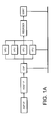
Figure 1A shows an architecture for generating a two
dimensional output for display on, say, a computer monitor,
such as that shown in Figure 6, based on representations of
one or more polygons in three dimensional space. In most
cases, including the preferred embodiment, the polygons will
take the form of triangles. This is because triangles are
always planar and convex, and therefore mathematically easier
to deal with than other polygons.
In Figure 1A, there is shown a graphics accelerator card 10
that includes an Accelerated Graphics Port (AGP) interface 11
connected to a host interface 12. The host interface is in
turn connected to a Command Stream Processor (CSP) 13. The CSP
has a variety of functions. For example, it interprets the
graphics command stream, differentiating between the vertex
information and the state information. It is responsible for
fetching data from the host. It can also reformat vertex data
into a form more suitable for the Vertex Processing Units
(VPUs) described below, packetising the data where necessary.
The CSP 13 is in communication with the video card system
memory (not shown) via an on-board bus 14, and is also
connected to a set of programmable Vertex Processing Units
(VPUs) 15 which are themselves connected to the bus 14 to
enable access to the video card and system memory.
The CSP controls the VPU processors 15 on the basis of
instructions from the host computer (as described later in
relation to Figure 6). The processed polygon data from the VPU
processors 15 is then reordered and sorted for display by
reordering and sorting circuitry 16 and 17 respectively.
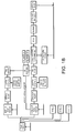
One of the VPU processors 15 will now be described in more
detail with reference to Figure 1B. The multiple VPU
processors 15 are substantially identical. The advantages and
disadvantages of pipelined processing are well understood.
However, the highly repetitive nature of calculations used in
video acceleration programming, along with the relatively
small number of branches and jumps (all of which behave
predictably) makes pipelining particularly well suited to this
type of processing.
Initially, triangles are set up for scan conversion. This is
shown in more detail in Figure 2, in which is shown an
exemplary triangle 200 ready for scan conversion. The triangle
200 is defined by set of three tuplets 201, 202 and 203 that
specify coordinates, colour and texture information at each
vertex. These tuplets are:
(X1 , Y1 , Z1 , R1 , G1 , B1 , A1 , U1 1 V1 1 , ..., U n 1 ,V n 1 )
(X2 , Y2 , Z2 , R2 , G2 , B2 , A2 , U1 2 , V1 2 , ..., U n 2 , V n 2 )
(X3 , Y3 , Z3 , R3 , G3 , B3 , A3 , U1 3 , V1 3 , ..., U n 3 , V n 3 )
The values represented by the variables will be well
understood by those skilled in the art of three-dimensional
graphics. The tuplet information represents values of vertices
of the triangle. By definition, this means that they lie in
the plane of the triangle, so the triangle can be rasterised
by interpolating the values at those vertices. Also, whilst
only one set of colour components (RGB) is defined in the
above tuplets, it is common for two sets to be defined, one
for diffuse lighting and the other for specular lighting.
As is shown in Figure 3, there are three states involved in
rasterising triangles:
In prior art methods, every pixel that passes the depth buffer
test is plotted. This means that, unless the triangles are
depth sorted and plotted from front to back, triangles that
will not ultimately be visible will still be rasterised.
Moreover, such triangles will also be texture mapped, which
places an undesirable burden on memory bandwidth.
In accordance with the preferred embodiment, this "overdraw"
problem is ameliorated by making a depth assessment of each
pixel prior to full rendering. In this way, only those
triangles that will actually be visible in the final image
will actually go through the relatively bandwidth-hungry
rendering stages. It will be appreciated by those skilled in
the art that this has the added advantage of speeding up
subsequent anti-aliasing procedures.
In the preferred embodiment, this result is achieved by
allocating a relatively unique identifier to each triangle to
be rendered. By "relatively unique", it is meant that each
triangle is uniquely identified with respect to all other
triangles that define the three dimensional components of a
particular tile or frame being rendered. For example, a
triangle that appears in consecutive frames or adjacent tiles
may well be allocated a different identifier in each of those
frames.
Referring to Figures 1 and 3, each triangle is rasterised to
translate the mathematically-defined triangle into a pixel-defined
triangle. Rasterising is well known to those skilled
in the art, and so will not be described in detail. Examples
of suitable rasterising techniques are described in "Computer
Graphics: Principles and Practice" by James Foley et al.
Figure 4 represents the steps involved in finding out which
triangles will be visible and therefore need to be rendered,
whilst Figure 5 represents the steps involved in plotting
colour/texture pixels to the colour buffer for the visible
pixels determined in Figure 4. Figure 9 summarises these steps
in a more simplified format.
Prior to the steps of Figure 4 being taken for a given frame
or title, each pixel location in the depth-buffer is set to a
"far distance" value, such that any pixel subsequently depth-compared
with one of the initial values will always be
considered "on top" of the initial value. It will be noted
that steps 402 to 408 of Figure 4 correspond with steps 502 to
508 to Figure 5, and in some embodiments can be performed in
the same hardware.
In step 409, a comparison is made between the depth value of
the current pixel and that representing the corresponding
pixel location in the depth-buffer. If the pixel already at
that position in the colour buffer has a depth greater than
that of the value at the corresponding position in the depth
buffer, then the identifier for the triangle being compared is
written into the triangle identification buffer and the depth
overwritten into that position in the depth buffer.
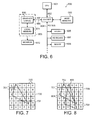
For the first triangle being scanned, the contents of the
identification buffer and the depth-buffer are shown in be
Figure 7. It will be noted that all values in the
identification buffer 700 are zero other than those pixel
locations 701 associated with the fist triangle 702.
Naturally, in alternative embodiments, any other default value
can be used to represent a "no triangle" state.
Each of the pixel locations corresponding to the pixels
generated in relation to the first triangle 702 contains the
value of the unique identifier originally allocated to the
triangle (in this case, the digit "1"). Each corresponding
pixel location in the depth-buffer has stored within it a z-value
associated with that pixel.
For subsequent triangles being scanned, the depth value of the
current pixel being scanned is compared to the depth value
stored in the pixel location in the depth-buffer corresponding
to that of the triangle. It will be appreciated that, if the
corresponding pixel location has not yet had triangle data
written to it, the pixel presently being considered will by
definition be visible in the event that no further triangles
have pixels at that location. The unique identifier associated
with the current triangle will then be written directly to the
corresponding pixel location to replace the default value.
The contents of the triangle identifier buffer after a second
triangle 800 has been written to it is shown in Figure 8,
along with the first triangle 702 from Figure 7. It will be
noted that the second triangle 800 is in front of the first
triangle 702 where they overlap, and so the unique identifier
801 of the second triangle (the digit "2") has been written
over the first triangle identifiers in the pixel locations
corresponding with the overlap area. Similarly, in the depth
buffer the depth values corresponding to the overlapping
second triangle have also overwritten the depth values of the
first triangle. Those portions of the second triangle 800 that
are not overlapping the first triangle 700 are also written to
the depth and triangle identifier buffers.
Steps 401 to 410 are repeated until all triangles for the
frame or tile being rendered have been processed. In the
present example, only the two triangles need to be rendered,
so the resultant triangle identifier buffer state is that
shown in Figure 8.
At this stage, the final rendering procedure shown in the
flowchart 500 of Figure 5 is implemented. The initial step 501
is to search the ID buffer to locate an active triangle. A
triangle can be considered active if one or more pixels
associated with it are in the depth-buffer. As each active
triangle is found, a corresponding set of vertices is
retrieved from memory.
Further steps are then undertaken in accordance with steps 502
to 505, which are known to those skilled in the art and
therefore not described in detail. Once step 507 is reached,
however, things proceed differently from the procedure of
Figure 4. The interpolate mask is still generated, in
accordance with step 508. However, r, g, b, a and z are then
interpolated in step 509 for each of the live pixels of
present triangle. The resultant values are then passed to the
texture pipe 510, in which texture mapping takes place. This
involves mapping a texture stored in memory to the triangle on
a pixel-by-pixel basis. The procedure is relatively well known
in the art, and so will not be described here in further
detail.
It will be noted from Figure 5 that there is some feed-forwarding
of data, in particular from the output of step 507
(to step 509) and step 508 (to step 511).
Once all pixels have been scanned and texture/colour mapped,
other processing, such as anti-aliasing, can be applied in
accordance with known procedures. The resultant frame,
representing a two-dimensional view of the three dimensional
representations, is output to a display device such as a
computer monitor.
Figure 9 shows a summarised version of the steps described in
relation to the other Figures. The steps themselves are self-explanatory
in view of the previous detailed description and
so will not be described in further detail herein.
Other architectures and approaches can be used in conjunction
with the invention. For example, it will be appreciated that
the invention is amenable to use with different triangle
plotting schemes, such as strips or fans. Also, the method can
be applied to entire frames, or sub-frames in the form of
tiles, depending upon the desired implementation. It will be
appreciated that additional steps may be required in some
cases to, for example, convert polygons (generated during
tiling or due to framing considerations) into triangles, but
this is well known within the art and so has not been
described further herein.
In the preferred form, the invention is embodied in a
specialist graphics processor on a graphics accelerator card.
Such cards are used as components in personal and business
computers, such as an IBM compatible PC 600 shown in Figure 6.
In the embodiment illustrated, the PC includes, amongst other
things, a general-purpose processor in the form of a Pentium
III processor 601, manufactured by the Intel Corporation. Via
a chipset 602, the processor 601 communicates with host memory
603, a PCI bus 604 and an Advanced Graphics Port (AGP) bus
605. The PCI bus 604 allows the chipset 602 to interface with
various peripheral components, such as a soundcard 606, a
keyboard 607 and a mouse 608. The AGP bus 605 is used to
communicate with a graphics accelerator card 609, which
includes, amongst other things, a graphics chip 610 and local
memory 611. The graphics card outputs graphics signals to a
computer monitor 612. The preferred embodiment of the present
invention is incorporated in the hardware, software and
firmware of the graphics card 609.
It will be seen from the detailed description that the present
invention provides a method of rendering polygons from a
three-dimensional to a two-dimensional space, whilst reducing
overall texture bandwidth requirements.
Although the invention has been described with reference to a
specific embodiment, it will be appreciated by those skilled
in the art that the invention can be embodied in many other
forms.
Claims (8)
- A method of rendering a plurality of triangles into a colour buffer defined by a plurality of pixel locations, utilising a triangle identification buffer and a depth buffer, the method including the steps of:(a) assigning a relatively unique identifier to each of the triangles to be rendered;(b) generating triangle pixels based on a first one of the triangles, each of the triangle pixels having associated with it an (x,y) position and a depth value;(c) writing the depth value associated with each of the pixels to pixel locations in the depth buffer, the pixel locations corresponding with the respective (x,y) positions generated in step (b);(d) writing the identifier associated with the triangle to the pixel locations in the buffer corresponding with the respective (x,y) positions generated in step (b); and(e) for each remaining triangle to be rendered:(i) generating triangle pixels, each of the triangle pixels having associated with it an (x,y) position and a depth value;(ii) comparing the depth value of at least some of the triangle pixels generated in (i) with the depth values stored at respective corresponding pixel locations in the depth buffer, thereby to determine for each pixel location whether the triangle whose identifier is already in the triangle identification buffer is in front of or behind the triangle being compared; and(iii) in the event that the triangle whose identifier is already in the triangle identification buffer is behind the triangle being compared at a given pixel location, writing the identifier of the triangle being compared into the identification buffer at that pixel location;(f) mapping colour data into the colour buffer on the basis of the contents of the triangle buffer once at least a plurality of the triangles has been depth compared.
- A method according to claim 1, wherein step (f) includes the substeps of:(i) selecting an identifier from the identifier buffer;(ii) retrieving from the triangle buffer the triangle associated with the selected identifier;(iii) rasterising the triangle, computing colour only, such that, for each pixel coordinate being considered, if the identification buffer contains the identifier of the triangle being rasterised, writing the colour value of the triangle at that coordinate to the colour buffer; and(iv) repeating substeps (i) to (iii) until the triangles associated with all identifiers in the identifier buffer have been rasterised.
- A method according to claim 1 or 2, wherein, in the event a triangle being rasterised in step (f) has a texture associated with it, step (f) further includes the substep of forwarding information to the texture cache to enable prefetching of the texture to commence.
- A method according to any one of the preceding claims, wherein the depth buffer and the triangle identification buffer are combined, such that, at each address defining a pixel location in the combined buffer, there is space for a depth value and a triangle identifier value.
- A method according to claim 4, wherein the depth buffer and triangle buffer are combined with the colour buffer, such that, at each address defining a pixel location in the combined buffer, there is space for the depth value the triangle identifier value and colour values.
- A method according to any one of the preceding claims, wherein the steps of generating triangle pixels include the sub-step of scan converting the triangles for which the pixels are to be generated.
- A method according to any one of the preceding claims, wherein the color data are based on textures stored in an associated texture memory.
- Computer apparatus having hardware components and being programmed with software, for implementing the method of any one of the preceding claims.
Priority Applications (3)
| Application Number | Priority Date | Filing Date | Title |
|---|---|---|---|
| EP01309059A EP1306810A1 (en) | 2001-10-25 | 2001-10-25 | Triangle identification buffer |
| EP02257324A EP1306811A1 (en) | 2001-10-25 | 2002-10-22 | Triangle identification buffer |
| US10/445,295 US20050231506A1 (en) | 2001-10-25 | 2003-05-22 | Triangle identification buffer |
Applications Claiming Priority (1)
| Application Number | Priority Date | Filing Date | Title |
|---|---|---|---|
| EP01309059A EP1306810A1 (en) | 2001-10-25 | 2001-10-25 | Triangle identification buffer |
Publications (1)
| Publication Number | Publication Date |
|---|---|
| EP1306810A1 true EP1306810A1 (en) | 2003-05-02 |
Family
ID=8182393
Family Applications (1)
| Application Number | Title | Priority Date | Filing Date |
|---|---|---|---|
| EP01309059A Withdrawn EP1306810A1 (en) | 2001-10-25 | 2001-10-25 | Triangle identification buffer |
Country Status (2)
| Country | Link |
|---|---|
| US (1) | US20050231506A1 (en) |
| EP (1) | EP1306810A1 (en) |
Families Citing this family (26)
| Publication number | Priority date | Publication date | Assignee | Title |
|---|---|---|---|---|
| US8687010B1 (en) | 2004-05-14 | 2014-04-01 | Nvidia Corporation | Arbitrary size texture palettes for use in graphics systems |
| US8743142B1 (en) | 2004-05-14 | 2014-06-03 | Nvidia Corporation | Unified data fetch graphics processing system and method |
| US8411105B1 (en) | 2004-05-14 | 2013-04-02 | Nvidia Corporation | Method and system for computing pixel parameters |
| US8711155B2 (en) | 2004-05-14 | 2014-04-29 | Nvidia Corporation | Early kill removal graphics processing system and method |
| US7079156B1 (en) | 2004-05-14 | 2006-07-18 | Nvidia Corporation | Method and system for implementing multiple high precision and low precision interpolators for a graphics pipeline |
| US8416242B1 (en) | 2004-05-14 | 2013-04-09 | Nvidia Corporation | Method and system for interpolating level-of-detail in graphics processors |
| US8736620B2 (en) | 2004-05-14 | 2014-05-27 | Nvidia Corporation | Kill bit graphics processing system and method |
| US8860722B2 (en) * | 2004-05-14 | 2014-10-14 | Nvidia Corporation | Early Z scoreboard tracking system and method |
| US8736628B1 (en) | 2004-05-14 | 2014-05-27 | Nvidia Corporation | Single thread graphics processing system and method |
| US20060007234A1 (en) * | 2004-05-14 | 2006-01-12 | Hutchins Edward A | Coincident graphics pixel scoreboard tracking system and method |
| US8432394B1 (en) | 2004-05-14 | 2013-04-30 | Nvidia Corporation | Method and system for implementing clamped z value interpolation in a raster stage of a graphics pipeline |
| KR101257849B1 (en) * | 2006-09-29 | 2013-04-30 | 삼성전자주식회사 | Method and Apparatus for rendering 3D graphic objects, and Method and Apparatus to minimize rendering objects for the same |
| US8537168B1 (en) | 2006-11-02 | 2013-09-17 | Nvidia Corporation | Method and system for deferred coverage mask generation in a raster stage |
| US8441497B1 (en) | 2007-08-07 | 2013-05-14 | Nvidia Corporation | Interpolation of vertex attributes in a graphics processor |
| US9183607B1 (en) | 2007-08-15 | 2015-11-10 | Nvidia Corporation | Scoreboard cache coherence in a graphics pipeline |
| ATE456111T1 (en) * | 2007-09-05 | 2010-02-15 | Vidiom Sa | METHOD FOR DRAWING GEOMETRIC SHAPES |
| US9256514B2 (en) | 2009-02-19 | 2016-02-09 | Nvidia Corporation | Debugging and perfomance analysis of applications |
| US9007374B1 (en) * | 2011-07-20 | 2015-04-14 | Autodesk, Inc. | Selection and thematic highlighting using terrain textures |
| US9411595B2 (en) | 2012-05-31 | 2016-08-09 | Nvidia Corporation | Multi-threaded transactional memory coherence |
| US9824009B2 (en) | 2012-12-21 | 2017-11-21 | Nvidia Corporation | Information coherency maintenance systems and methods |
| US10102142B2 (en) | 2012-12-26 | 2018-10-16 | Nvidia Corporation | Virtual address based memory reordering |
| US9477575B2 (en) | 2013-06-12 | 2016-10-25 | Nvidia Corporation | Method and system for implementing a multi-threaded API stream replay |
| US9569385B2 (en) | 2013-09-09 | 2017-02-14 | Nvidia Corporation | Memory transaction ordering |
| GB2520366B (en) * | 2013-12-13 | 2015-12-09 | Imagination Tech Ltd | Primitive processing in a graphics processing system |
| GB2520365B (en) | 2013-12-13 | 2015-12-09 | Imagination Tech Ltd | Primitive processing in a graphics processing system |
| GB2569546B (en) * | 2017-12-19 | 2020-10-14 | Sony Interactive Entertainment Inc | Determining pixel values using reference images |
Citations (1)
| Publication number | Priority date | Publication date | Assignee | Title |
|---|---|---|---|---|
| EP0606685A1 (en) * | 1993-01-15 | 1994-07-20 | International Business Machines Corporation | Method and apparatus for reducing illumination calculations through efficient visibility determination |
Family Cites Families (15)
| Publication number | Priority date | Publication date | Assignee | Title |
|---|---|---|---|---|
| US4594673A (en) * | 1983-06-28 | 1986-06-10 | Gti Corporation | Hidden surface processor |
| US4697178A (en) * | 1984-06-29 | 1987-09-29 | Megatek Corporation | Computer graphics system for real-time calculation and display of the perspective view of three-dimensional scenes |
| US4855938A (en) * | 1987-10-30 | 1989-08-08 | International Business Machines Corporation | Hidden line removal method with modified depth buffer |
| US5249264A (en) * | 1988-11-14 | 1993-09-28 | International Business Machines Corporation | Image display method and apparatus |
| US5509110A (en) * | 1993-04-26 | 1996-04-16 | Loral Aerospace Corporation | Method for tree-structured hierarchical occlusion in image generators |
| KR100243179B1 (en) * | 1994-06-30 | 2000-02-01 | 윤종용 | Method and apparatus for processing signal of graphic system |
| JPH0855239A (en) * | 1994-07-21 | 1996-02-27 | Internatl Business Mach Corp <Ibm> | Method and apparatus for judgment of visibility of graphicalobject |
| US5600763A (en) * | 1994-07-21 | 1997-02-04 | Apple Computer, Inc. | Error-bounded antialiased rendering of complex scenes |
| US5808617A (en) * | 1995-08-04 | 1998-09-15 | Microsoft Corporation | Method and system for depth complexity reduction in a graphics rendering system |
| JPH0969163A (en) * | 1995-08-31 | 1997-03-11 | Fujitsu Ltd | Method for extracting overlap of polygons in computer graphic model and method and device for grouping polygons |
| US5751291A (en) * | 1996-07-26 | 1998-05-12 | Hewlett-Packard Company | System and method for accelerated occlusion culling |
| JPH10334269A (en) * | 1997-06-03 | 1998-12-18 | Sega Enterp Ltd | Image processing device and method, and recording medium recording image processing program |
| US6369813B2 (en) * | 1998-06-30 | 2002-04-09 | Intel Corporation | Processing polygon meshes using mesh pool window |
| US6295068B1 (en) * | 1999-04-06 | 2001-09-25 | Neomagic Corp. | Advanced graphics port (AGP) display driver with restricted execute mode for transparently transferring textures to a local texture cache |
| US6407736B1 (en) * | 1999-06-18 | 2002-06-18 | Interval Research Corporation | Deferred scanline conversion architecture |
-
2001
- 2001-10-25 EP EP01309059A patent/EP1306810A1/en not_active Withdrawn
-
2003
- 2003-05-22 US US10/445,295 patent/US20050231506A1/en not_active Abandoned
Patent Citations (1)
| Publication number | Priority date | Publication date | Assignee | Title |
|---|---|---|---|---|
| EP0606685A1 (en) * | 1993-01-15 | 1994-07-20 | International Business Machines Corporation | Method and apparatus for reducing illumination calculations through efficient visibility determination |
Non-Patent Citations (1)
| Title |
|---|
| YU Y: "Efficient visibility processing for projective texture mapping - principles and practice", COMPUTERS AND GRAPHICS, PERGAMON PRESS LTD. OXFORD, GB, vol. 23, no. 2, April 1999 (1999-04-01), pages 245 - 253, XP004165788, ISSN: 0097-8493 * |
Also Published As
| Publication number | Publication date |
|---|---|
| US20050231506A1 (en) | 2005-10-20 |
Similar Documents
| Publication | Publication Date | Title |
|---|---|---|
| EP1306810A1 (en) | Triangle identification buffer | |
| US5790134A (en) | Hardware architecture for image generation and manipulation | |
| KR100896155B1 (en) | Flexible antialiasing in embedded devices | |
| US6891533B1 (en) | Compositing separately-generated three-dimensional images | |
| US10957082B2 (en) | Method of and apparatus for processing graphics | |
| US8659589B2 (en) | Leveraging graphics processors to optimize rendering 2-D objects | |
| US6038031A (en) | 3D graphics object copying with reduced edge artifacts | |
| US5909219A (en) | Embedding a transparency enable bit as part of a resizing bit block transfer operation | |
| US6259461B1 (en) | System and method for accelerating the rendering of graphics in a multi-pass rendering environment | |
| US8044955B1 (en) | Dynamic tessellation spreading for resolution-independent GPU anti-aliasing and rendering | |
| US7098922B1 (en) | Multiple data buffers for processing graphics data | |
| US20020122036A1 (en) | Image generation method and device used therefor | |
| US20130127858A1 (en) | Interception of Graphics API Calls for Optimization of Rendering | |
| JPH0695636A (en) | Method and apparatus for generating color pallet, data processing system and method for generating input for lookuptable | |
| US6731289B1 (en) | Extended range pixel display system and method | |
| CN109785417B (en) | Method and device for realizing OpenGL cumulative operation | |
| US20050068326A1 (en) | Image processing apparatus and method of same | |
| US6791561B1 (en) | Method and apparatus for rendering video data | |
| JP2007517330A (en) | Programmable filtering method and apparatus for texture map data in a three-dimensional graphics subsystem | |
| US6567098B1 (en) | Method and apparatus in a data processing system for full scene anti-aliasing | |
| US20030214508A1 (en) | System for alpha blending and method thereof | |
| KR100233346B1 (en) | Method and apparatus for improving graphics picking using auxiliary buffer information | |
| KR20180038793A (en) | Method and apparatus for processing image data | |
| KR20080100854A (en) | Rendering processing method, rendering processing device, and computer-readable recording medium having recorded therein a rendering processing program | |
| US6867778B2 (en) | End point value correction when traversing an edge using a quantized slope value |
Legal Events
| Date | Code | Title | Description |
|---|---|---|---|
| PUAI | Public reference made under article 153(3) epc to a published international application that has entered the european phase |
Free format text: ORIGINAL CODE: 0009012 |
|
| AK | Designated contracting states |
Designated state(s): AT BE CH CY DE DK ES FI FR GB GR IE IT LI LU MC NL PT SE TR |
|
| AX | Request for extension of the european patent |
Extension state: AL LT LV MK RO SI |
|
| AKX | Designation fees paid | ||
| REG | Reference to a national code |
Ref country code: DE Ref legal event code: 8566 |
|
| STAA | Information on the status of an ep patent application or granted ep patent |
Free format text: STATUS: THE APPLICATION IS DEEMED TO BE WITHDRAWN |
|
| 18D | Application deemed to be withdrawn |
Effective date: 20031104 |