EP1300964B1 - A system and method for measuring crosstalk in XDSL networks - Google Patents
A system and method for measuring crosstalk in XDSL networks Download PDFInfo
- Publication number
- EP1300964B1 EP1300964B1 EP01402558A EP01402558A EP1300964B1 EP 1300964 B1 EP1300964 B1 EP 1300964B1 EP 01402558 A EP01402558 A EP 01402558A EP 01402558 A EP01402558 A EP 01402558A EP 1300964 B1 EP1300964 B1 EP 1300964B1
- Authority
- EP
- European Patent Office
- Prior art keywords
- port
- network
- model
- transmission line
- parameters
- Prior art date
- Legal status (The legal status is an assumption and is not a legal conclusion. Google has not performed a legal analysis and makes no representation as to the accuracy of the status listed.)
- Expired - Lifetime
Links
- 238000000034 method Methods 0.000 title claims abstract description 69
- 230000005540 biological transmission Effects 0.000 claims abstract description 112
- 238000012546 transfer Methods 0.000 claims description 74
- 238000005259 measurement Methods 0.000 claims description 65
- 230000005284 excitation Effects 0.000 claims description 17
- 238000004590 computer program Methods 0.000 claims description 8
- 238000001228 spectrum Methods 0.000 claims description 5
- 238000012545 processing Methods 0.000 claims description 4
- 238000011002 quantification Methods 0.000 claims description 4
- 230000006870 function Effects 0.000 description 114
- 238000005457 optimization Methods 0.000 description 18
- 239000004020 conductor Substances 0.000 description 12
- 239000000463 material Substances 0.000 description 11
- 239000004698 Polyethylene Substances 0.000 description 9
- 229920000573 polyethylene Polymers 0.000 description 9
- RYGMFSIKBFXOCR-UHFFFAOYSA-N Copper Chemical compound [Cu] RYGMFSIKBFXOCR-UHFFFAOYSA-N 0.000 description 7
- 238000004891 communication Methods 0.000 description 7
- 238000004422 calculation algorithm Methods 0.000 description 6
- 238000012512 characterization method Methods 0.000 description 6
- 229910052802 copper Inorganic materials 0.000 description 6
- 239000010949 copper Substances 0.000 description 6
- 230000008878 coupling Effects 0.000 description 6
- 238000010168 coupling process Methods 0.000 description 6
- 238000005859 coupling reaction Methods 0.000 description 6
- 238000004458 analytical method Methods 0.000 description 5
- 238000004364 calculation method Methods 0.000 description 5
- 238000012360 testing method Methods 0.000 description 5
- 238000011144 upstream manufacturing Methods 0.000 description 5
- 238000012897 Levenberg–Marquardt algorithm Methods 0.000 description 4
- 230000003287 optical effect Effects 0.000 description 4
- 230000003595 spectral effect Effects 0.000 description 4
- 238000007476 Maximum Likelihood Methods 0.000 description 3
- 238000009413 insulation Methods 0.000 description 3
- 230000002093 peripheral effect Effects 0.000 description 3
- 230000004044 response Effects 0.000 description 3
- 238000010200 validation analysis Methods 0.000 description 3
- -1 Polyethylene Polymers 0.000 description 2
- 239000011230 binding agent Substances 0.000 description 2
- 238000007796 conventional method Methods 0.000 description 2
- 230000000875 corresponding effect Effects 0.000 description 2
- 238000009795 derivation Methods 0.000 description 2
- 238000010586 diagram Methods 0.000 description 2
- 230000002500 effect on skin Effects 0.000 description 2
- 230000000694 effects Effects 0.000 description 2
- 238000011478 gradient descent method Methods 0.000 description 2
- 230000002452 interceptive effect Effects 0.000 description 2
- 238000000691 measurement method Methods 0.000 description 2
- 239000013307 optical fiber Substances 0.000 description 2
- 238000002310 reflectometry Methods 0.000 description 2
- 238000004088 simulation Methods 0.000 description 2
- 101150012579 ADSL gene Proteins 0.000 description 1
- 102100020775 Adenylosuccinate lyase Human genes 0.000 description 1
- 108700040193 Adenylosuccinate lyases Proteins 0.000 description 1
- 208000032369 Primary transmission Diseases 0.000 description 1
- VRDIULHPQTYCLN-UHFFFAOYSA-N Prothionamide Chemical compound CCCC1=CC(C(N)=S)=CC=N1 VRDIULHPQTYCLN-UHFFFAOYSA-N 0.000 description 1
- 230000008901 benefit Effects 0.000 description 1
- 230000008859 change Effects 0.000 description 1
- 238000010276 construction Methods 0.000 description 1
- 230000001276 controlling effect Effects 0.000 description 1
- 230000002596 correlated effect Effects 0.000 description 1
- 230000001186 cumulative effect Effects 0.000 description 1
- 238000013500 data storage Methods 0.000 description 1
- 230000007423 decrease Effects 0.000 description 1
- 230000006735 deficit Effects 0.000 description 1
- 230000001066 destructive effect Effects 0.000 description 1
- 238000005516 engineering process Methods 0.000 description 1
- 239000000835 fiber Substances 0.000 description 1
- 238000007429 general method Methods 0.000 description 1
- 230000001939 inductive effect Effects 0.000 description 1
- 239000012212 insulator Substances 0.000 description 1
- 230000005055 memory storage Effects 0.000 description 1
- 230000000737 periodic effect Effects 0.000 description 1
- 230000008569 process Effects 0.000 description 1
- 230000001902 propagating effect Effects 0.000 description 1
- 238000012797 qualification Methods 0.000 description 1
- 230000009467 reduction Effects 0.000 description 1
- 230000001131 transforming effect Effects 0.000 description 1
- 230000000007 visual effect Effects 0.000 description 1
Images


Classifications
-
- H—ELECTRICITY
- H04—ELECTRIC COMMUNICATION TECHNIQUE
- H04B—TRANSMISSION
- H04B3/00—Line transmission systems
- H04B3/02—Details
- H04B3/46—Monitoring; Testing
- H04B3/487—Testing crosstalk effects
Definitions
- the present invention relates to simulation methods for telecommunications networks and to telecommunications networks themselves having a plurality of transmission lines with receivers and transmitters connected by some form of communications channel which is subject to crosstalk.
- the present invention is especially useful for the prediction and adjustment of network parameters such as a transmission powers, in particular for use in xDSL networks as well as for simulating such networks.
- xDSL stands for the family of Digital Subscriber Line technologies, which allow high-speed access to the Internet and multimedia services over the local loop, which connects the CP (customer premises) to the CO (central office), that is over simple twisted pair cables.
- An xDSL transceiver at the CO communicates with an xDSL transceiver at the CP over the local loop.
- the POTS signal transmitted over the local loop, is analog and contained in the frequency band up to 4 kHz, which corresponds to the spectral content of speech.
- SNR signal-to-noise ratio
- the SNR at the receiver at the CP, respectively the CO is determined as a function of the frequency by the transfer function of the loop between the CO and the CP and the noise PSD (Power Spectral Density) at the CP, respectively the CO given the PSD of the transmitted signal at the CO, respectively the CP.
- the local loop consists of a network of transmission lines. Every line in the network is a UTP characterized by its length and type.
- the line type specifies the cross-sectional geometrical dimensions, such as the wire diameter (also called wire gauge), and the material physical constants, such as the electrical permittivity of the dielectric separating the 2 copper wires.
- the most used wire diameters are 0.4 mm, 0.5 mm, and 0.6 mm.
- Polyethylene (PE) is the most occurring insulator but other materials are also used such as paper and PVC.
- the network topology of the local loop is limited to a tree structure.
- the simplest topology is a single line.
- the magnitude of the transfer function reflects the attenuation of the line, which gets worse with increasing frequency and line length.
- Another topology that exists for long loops is a cascade of 2 or more lines with increasing wire diameter from the CO to the CP. For this topology reflections are caused by the change of the wire diameter at the splices connecting 2 lines.
- a topology that is also frequently encountered, especially in the USA, is a loop with 1, 2 or more bridged taps.
- a bridged tap is an open-ended line spliced to the main line. Reflections appear for this topology at the splice connecting the bridged tap to the loop and at the open end of the bridged tap.
- Reflections have a negative impact on the transfer function, because they interfere with the signal propagating along the direct path. For those frequencies for which the interference is destructive, the magnitude of the transfer function reduces. Such reductions rarely appear in the voice band because the bridged taps are usually not too long.
- the noise is divided into 2 different types according to the origin of the external electromagnetic waves coupling into the loop.
- the first type of noise is crosstalk, which is the electromagnetic coupling between twisted pairs in the same cable or between cables.
- the cables leaving the CO contain thousands of twisted pairs. The closer to the CP the less pairs there are present in a cable.
- a difference is made between near-end crosstalk (NEXT) and far-end crosstalk (FEXT).
- the transmitters at the CO, respectively CP are the source of NEXT for the near-end receivers at the CO, respectively the CP, and are the source of FEXT for the far-end receivers at the CP, respectively the CO.
- crosstalk gets worse with increasing frequency.
- a second type of noise is radio-frequency interference (RFI), which is caused by radio waves coupling into the local loop, that acts as an antenna, especially if there are aerial lines.
- RFID radio-frequency interference
- the local loop has several impairments for transmission in the frequency band of xDSL, which are not present for voice-band transmission.
- Upstream power backoff guarantees spectral compatibility between long and short loops that are operating in the same cable binder.
- UPBO is a method by which the upstream power spectrum density (PSD transmit ) being generated by a transmitter on a short disturber line is controlled in order to limit excessive crosstalk into neighbouring lines.
- PSD transmit upstream power spectrum density
- the crosstalk measured at the line terminator of the victim loop impacts on the bit rate performance of the victim loop.
- a current method of UPBO is based on an estimation of the length of the loop. The electrical length is obtained by comparing the attenution of the loop under consideration with the attenuation of a reference loop. This reference loop consists of a single line segment.
- the PSD transmit is determined by (PSD ref ) /
- a system and methodology for qualifying a twisted pair copper loop for digital subscriber loop services are described in the US Patent with Patent N° US 6,292,539 with Date of patent dd. Sept. 1 8, 2001.
- the system automatically queries telecommunications provider database records and/or requests measurements from network switching equipment or testing systems to obtain data regarding the twisted pair copper loop, such as loop length, electrical characteristics, and other loop topology characteristics such as wire qauge, the presence of load coils, and the presence of bridge taps.
- the system determines which digital subscriber loop services are available for the copper loop based on the combination of all data obtained.
- the system may be implemented in part as an expert system with a knowledge base qualification rules used in the decision-making process.
- An aspect of the present invention may be described as a method and apparatus for modeling a network comprising a plurality of transmission lines, the method and system being adapted to measure loop parameters of a transmission line to provide measured loop parameters, determine a topology of the first transmission line by analysing the measured loop parameters with reference to at least a one model of a plurality of models for transmission lines of different topologies, select a further model for estimating crosstalk related parameters based on the determined topology, and estimate at least one crosstalk related parameter based on the determined topolgy and the selected further model.
- the method may include determining a transmit power spectrum for a transmitter on the network in accordance with the estimated crosstalk related parameter.
- the crosstalk related parameter may be a transfer function for at least one of FEXT, NEXT, alien-NEXT, alien-FEXT, EL-FEXT, EL-NEXT, self-NEXT, self-FEXT.
- the measuring step may include carrying out a two-port measurement of the transmission line by inputting an excitation signal at one port of the transmission line and measuring the received signal at another port of the transmission line; deriving from the received signal a transfer function of the transmission line; generating a 2-port parametric model of the transmission line; and optimising values of the parameters of the 2-port parametric model by reducing the difference between the derived transfer function and a transfer function calculated from the at least one model.
- the measuring step may comprise carrying out a 1 port measurement on the network by inputting an excitation signal at one port of the network and recording the results at the port; generating a 1 port parametric model of the network; and optimising the values of the parameters of the 1 port parametric model by reducing the difference between the results of the measurement step and results calculated using the 1-port parametric model and the excitation signal.
- the reducing step may be carried out by minimizing a cost function by adapting the values of the parameters of the relevant parametric model, the cost function representing a quantification of the difference.
- the method may comprise the step of determining a length of the transmission line as an output of the optimising step.
- an estimation of the end-to-end transfer function of at least one transmission line is based on measurements at one termination location thereof only or at two or more locations.
- the invention includes the characterization of the transmission line even though its length and topology is unknown. This characterisation can be used to predict the transfer function for the line. Alternatively, the transfer function may be measured directly, e.g. by using tones emitted from modems at each end of the transmission line.
- an excitation signal is generated at one or more termination locations thereof, e.g. at a central-office end of a local loop depending on which method is used to obtain the transfer function. For the single port measurement method a response signal is measured at the same location as the excitation signal is generated.
- This excitation signal corresponds to the incident wave and the response signal to the reflected wave.
- the latter is also called reflectogram.
- This measurement procedure is called reflectometry (time-domain reflectometry, or TDR, if the signals are measured in the time domain).
- the ratio of the reflected wave and the incident wave is defined as the scattering parameter S 11 (also called reflection factor in the case of a 1-port). So the scattering parameter S 11 of a certain transmission line describes how that line responds in terms of a reflected wave, if it is excited with a certain incident wave.
- the complete model of the line considered as a 2-port consists of the 4 scattering parameters S 11 , S 21 , S 12 , and S 22 .
- the transfer function is related to the scattering parameter S 21 .
- a transmission loop e.g. a local loop usually consists of a network of transmission lines connecting the customer premises to the central office.
- the network topology is limited to a tree structure. Every line in the network is characterized by its length and type.
- the line type specifies the cross-sectional geometrical dimensions and the material constants.
- the excitation signals are entered at each end of the transmission line separately and the received signal measured at the other end.
- the above methods may include a step of reducing the difference between measured values (two port or one port) and the model by:
- the at least one transmission line can be a local loop of an access network.
- the present invention may also provide a system for modeling a network, comprising: means for measuring loop parameters of first transmission line to provide measured loop parameters, means for determining a topology of the first transmission line by analysing the measured loop parameters with reference to at least a one model of a plurality of models for transmission lines of different topologies, means for selecting a further model for estimating crosstalk related parameters based on the determined topology, and means for estimating at least one crosstalk related parameter based on the determined topolgy and the selected further model.
- the system may comprise means for determining a transmit power spectrum for a transmitter on the network in accordance with the estimated crosstalk related parameter.
- the crosstalk related parameter may be a transfer function for at least one of FEXT, NEXT, alien-NEXT, alien-FEXT, EL-FEXT, EL-NEXT, self-NEXT, self-FEXT.
- the means for measuring may include means for carrying out a two-port measurement of the transmission line by inputting an excitation signal at one port of the transmission line and measuring the received signal at another port of the transmission line, further comprising means for deriving from the received signal a transfer function of the transmission line; means for generating a 2-port parametric model of the transmission line; and means for optimising values of the parameters of the 2-port parametric model by reducing the difference between the derived transfer function and a transfer function calculated from the at least one model.
- the means for measuring may comprise means for carrying out a 1 port measurement on the network by inputting an excitation signal at one port of the network and recording the results at the port; further comprising: means for generating a 1 port parametric model of the network; and means for optimising the values of the parameters of the 1 port parametric model by reducing the difference between the results of the measurement step and results calculated using the 1-port parametric model and the excitation signal.
- the means for optimising may include means for reducing the difference by minimizing a cost function by adapting the values of the parameters of the relevant parametric model, the cost function representing a quantification of the difference.
- the means for optimising may include means for determining a length of the transmission line.
- inclmude processing means including means for estimating a transfer function of said at least one transmission line.
- the means for reducing the difference may include:
- the above systems may include means for outputting at least one of:
- the above systems for modeling may be included in a central office system of a telecommunications network.
- the present invention also includes a data carrier medium carrying one or more computer readable code segments for controlling a processing device to carry out any method in accordance with the present invention.
- the present invention also includes a computer program product for execution of any of the methods in accordance with the present invention on a computer system.
- the present invention also includes a method for modelling a representation of network, said method comprising:
- the application of the present invention is not limited in this respect and it can be used for symmetric or asymmetric lines, for example in the case of coaxial cables, optical fibers, etc. and even in the case of a general 2-port network. Further, the invention will mainly be described with reference to FEXT but the present invention is not limited thereto but can be applied to other forms of crosstalk such as NEXT, alien-NEXT (influences by electromagnetic interference from outside the network), alien-FEXT, EL-FEXT, EL-NEXT, self-NEXT, self-FEXT.
- a general reference book for xDSL is " ADSL, VDSL and multicarrier modulation", by John Bingham, Wiley, 2000 . The following references may also be found useful for understanding the present invention.
- the present invention may be summarised as follows.
- One or more measurements of a transmission loop of a communications network are made. These measurements are compared with one or more parametric models of predefined loop topologies.
- the parameters of each topology model are optimised to give the best fit to the measurement results. This optimisation may be done by minimising or maximising a cost function.
- a best fit topology is determined, i.e. a topology is chosen which corresponds to the best fit model to the measured results.
- Parameters available from the parametric model are fed into a parametric crosstalk model of the same topology as the best fit topology. This crosstalk model is used to obtain a crosstalk-related parameter of the network, e.g.
- a step in the above method is obtaining the transfer function of a loop. This can be obtained by two-port or on-port measurements in accordance with separate embodiments of the present invention.
- a 1-port parametric model for the S 11 scattering parameter of the network is derived from the models for individual line sections of the network or based on an assumed model.
- an S 11 scattering parameter model the parameters of the individual lines appear as independently identifiable parameters. It is then possible to model the loop completely by only measuring the scattering parameter S 11 .
- the unknown parameters have to be estimated by a further optimization routine.
- the optimized parameters are used in a 2-port model of the network for further analysis of the network.
- each line in a network is fully characterized by a parametric model, which consists of the characteristic impedance and the transfer function of the line as a function of the frequency and a number of unknown parameters.
- a parametric model which consists of the characteristic impedance and the transfer function of the line as a function of the frequency and a number of unknown parameters.
- Several line models are available. A model based on electromagnetic theory is one of the most useful for the line characterization. This model is based on the 4 primary transmission line parameters, which are resistance, inductance, conductance, and capacitance, as a function of the frequency and a number of parameters related to the cross-sectional geometrical dimensions and material constants. These latter parameters are considered to be unknown. In the following, it will be assumed that the transmission line comprises twisted pair cables. For other cable types, equivalent models may be selected.
- the electromagnetic model assumes that the wire for the local loop comprises 2 cylindrical conductors with the same diameter immersed in a homogeneous dielectric. It allows for the skin effect and the proximity effect (up to 2 terms in the Fourier series solution). It contains 5 independently identifiable parameters, which are related to the cross-sectional geometric dimensions and material constants of the components of the twisted pair cables.
- the electrical permittivity of the dielectric is considered to be independent of the frequency in this model and the conductance is neglected, which are good approximations for polyethylene (PE).
- PE polyethylene
- Parameter estimation is an important part of characterization of a loop in accordance with the present invention.
- the difference between measured values for a loop and the modeled values for the same loop is reduced by appropriate selection/determination of the unknown parameters.
- a cost function may be introduced which quantifies the deviation between the measured values (reflectogram) and the result of modeling the scattering parameter S 11 of the loop as a function of the model parameters.
- the cost function is minimized as a function of the model parameters.
- the values of the model parameters corresponding to this minimum are the estimated values of the parameters.
- the lower limit of the variance of the estimated parameters may given by any suitable method, e.g. by the Cramer-Rao lower bound.
- the cost function is also called an estimator, because it determines the parameter estimation completely.
- estimators are available.
- the maximum likelihood estimator (MLE) is preferred because it is consistent, asymptotically unbiased, asymptotically normally distributed, and asymptotically efficient under certain noise assumptions. In addition it is robust. It has such good properties because it takes the noise in the measurement into account. This means of course that this noise has to be measured.
- the characterization is typically performed in the frequency domain and the measurement in the time domain but the present invention is not limited thereto. Measurements and characterization may be performed in either the time domain or the frequency domain.
- the minimum of the cost function as a function of the model parameters is found by means of an optimization algorithm. Typically, this optimization algorithm will be iterative There are several known optimization routines which may be used.
- the Levenberg-Marquardt (LM) method is preferred. It combines the Gauss-Newton and gradient descent procedures. The Gauss-Newton method is very fast, because it makes use of second-order derivatives, but it does not always converge. This problem of convergence is solved in the Levenberg-Marquardt algorithm by addition of the gradient descent method. The Levenberg-Marquardt algorithm only searches for a local minimum.
- the initial values of the model parameters are preferably chosen to be close enough to the exact values, which correspond to the global minimum of the cost function so that the optimization does not become trapped in a local mimimum.
- the estimated parameters are available for all the individual lines, the loop is completely modeled and the estimated transfer function can be calculated.
- a suitable optimization is based on a S 11 scattering parameter measurement, an MLE cost function and an LM optimization algorithm.
- the S 11 scattering parameter model depends on the network topology and the model for the individual line sections. For every different network topology and line model there is a different S 11 scattering parameter model. This model has to be calculated. Independently identifiable parameters have to be determined. The derivatives of the model to its parameters have to be computed, because they are needed for the Jacobian in the LM optimization algorithm.
- an alternative method in accordance with an embodiment of the present invention tries each one of a series of well known topologies and makes an optimization of the unknown parameters for each topology by comparison with the reflectogram.
- the topology which appears to give the best fit with the reflectogram may then taken as the best fit topology for the calculation of the network capacity.
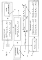
- a 1-port parametric model 2 having a finite number of coefficients whose values need to be optimised is generated in step 1 for a network based on an actual or assumed topolgy 3 for the network.
- a 1-port measurement 4 is carried out in step 5 on the network to be analysed.
- a measurement of the scattering parameter S 11 may be carried out, but the present invention is not limited thereto - the input impedance Zin could equally well be used.
- This measurement is used to do the parameter optimisation of the 1-port model 6 of the network in step 7.
- these estimated parameters 9 can be included within a 2-port parametric model 10 for the access network based on a transmission line model for every line segment to compute the estimated transfer function H in step 8.
- this end-to-end transfer function can be validated with the measured transfer function (see later) and the transfer function estimated directly via the transfer function measurement, however, this is only for validation purposes.
- the present invention is not limited to access networks of telephone networks, it can be used for any medium used for transmission where there is a transmitter - medium - receiver structure.
- 1 port measurements at transmitter or receiver side can be made and these used to optimisze a parametric 1-port model for the medium.
- the parametric model preferably has a limited set of parameters.
- the parameters of the transmission medium model are optimised and then used to determine a 2-port model for the network.
- the transmission medium could be any one suitable for a coimmunications system, e.g. a network of twisted pair lines, coaxial lines, optical fibers, the air interface of a mobile teleocmmunications network.
- a transmission line or a combination or network of transmission lines is modelled by a parametric model having a finite number of coefficients to be determined, e.g. 5 coefficients a 1 to a 5 for each "basic transmission line" or transmission line primitive.
- a transmission line primitive can comprise a twisted pair cable such as is used conventionally for the local loop of a public telephone system or, for instance, a twisted pair connection between two network devices on a Local Area Network.
- each transmission line primitive is represented by the above parametric model - that is the network is modeled by a set of individual parametric models, one of each transmission line primitive and each having a finite number of coefficients to be determined.
- Some of the coefficients may be estimated initially by calculating an initial value based on characteristics of the relevant transmission line, e.g. physical constants of materials used in the connecting cable forming the transmission line. Other coefficients may be selected, e.g. a 4 ., however it is preferred if these coefficients are also determined so as to bring the initial model close to the optimized one. Knowledge of the actual topology of the network or of a finite number of topologies which the network may have can be used to set up the parametric model.
- the reflectogram of the network is measured experimentally from one access point or "port" of the network.
- a suitable test wave or pulse is entered at the relevant port and reflected waves measured at the port.
- This reflectogram is preferably stored in a manner that allows manipulation of the reflectogram within a digital computing device, e.g. the reflectogram may be converted to digital signals using an analogue to digital converter.
- the finite number of coefficients of the paramteric model are optimized so as to give a close (or at least a closer fit than the initial values) between a characteristic of the network as modeled and the reflectogram. This comparison may be done in the time domain or the frequency domain. In the following only a comparison in the frequency domain will be described.
- an optimization routine may be used to optimize the coefficients of the parametric model.
- the optimization may be done with respect to a cost function. That is, the goodness of fit between the reflectogram and the results predicted by the parametric model (e.g. a difference) may be represented as a quantitative value, and the coefficients may be optimized with reference to this value. For instance, this value may be maximized or minimized depending on whether the chosen value is a large or small value, respectively when there is a good fit.
- the routine may stop in a local minimum or maximum and not an absolute one.
- the present invention makes use of a quasi-realistic model of the network so that there is some correlation between at least certain coefficients of the parametric model and physical constants of the network. By this means at least some of initial values of the parameters should be close to their final optimized ones and therefore there is less chance that the optimization routine lands in a local minimum. This is a significant advantage of the present invention compared with fully heuristic or pragmatic models for which initial values cannot be calculated reliably from network materials and topologies.
- the optimized parameters may be used in a 2-port parametric model of the network to determine crosstalk-related parameters as explained above.
- the initial value of a 4 is preferably chosen as a combination of initial values of a 1 , a 2 , and a 3 as explained in ref. 1 which is incorporated herewith by reference.
- a 5 Cl
- This transmission line model for twisted pair is based on electromagnetic theory, so it is physical, white-box model (as opposed to black box), that contains as much a priori knowledge as possible.
- the model includes the skin effect and proximity effect (up to 2 terms of the series solution) and is considered to be suitable for the best mode of operation of the present invention for twisted pair cables.
- the present invention is not however, limited to this method.
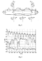
- Figure 1 depicts an equivalent electrical circuit of an access network consisting of a single line.
- Initial values of five parameters, a 1 a 2 a 3 a 4 a 5 , of the basic parametric model need to be determined and then optimized.
- the aim of the modelling exercise is to obtain an expression for S 11 (1-port model, used for the parameter estimation) and H, the transfer function (2-port model, needed for capacity estimation and validation).
- the transmit PSD power spectral density
- Figure 2 depicts an equivalent electrical circuit of an access network consisting of a loop with a bridge tap.
- Initial values of seven parameters, a 1 a 2 a 3 a 4 a 5 a 6 a 7 of the parametric model need to be determined and then optimized.
- the aim of the modeling exercise is to obtain an expression for S 11 , the scattering function and H, the transfer function.
- Figure 3 depicts an equivalent electrical circuit of an access network consisting of a cascade of two lines.
- Initial values of ten parameters a 11 a 21 a 31 a 41 a 51 a 12 a 22 a 32 a 42 a 52 of the parametric model need to be determined and then optimized.
- the aim of the modeling exercise is to obtain an expression for S 11 , the scattering function and H, the transfer function.
- cost function for use in optimizing the parameters of the parametric model, but the present invention is not limited thereto. It is called maximum likelihood for the output error model.
- This first cost function in S 11 is important for the general method in accordance with the present invention.
- the optimization of parameters is carried out by minimizing a difference represented by the cost function.
- the preferred minimizer is from Levenbergh-Marquardt but the present invention is not limited to this type of optimization algorithm, nor to any parrticular values for the starting values.
- the reflectogram of the network is measured for a specific excitation signal.
- the RBW was 100 Hz, sweep time 2 min, and 401 points were recorded.
- Four measurements were performed of S 11 and H in each case to be able compute mean and variance values. These latter values are used as weighting factors in the MLE cost function (see equation 26)
- the transmission lines used were cables, e.g. as supplied by Belgacom (Belgium), having a conductor diameter of 0.5 mm, a PE insulation, and 20 pairs in the form of quads; as supplied by BT (UK), having a conductor size of 0.5 mm, insulation of PE, 20 pairs; as supplied by FT (France), having conductor size of 0,4 mm, PE insulation, 8 pairs, quads.
- Belgacom Belgium
- BT BT
- FT France
- the North Hill balance was 50 Ohm to 135 Ohm
- All segments of cable were BT cable with conductor size of 0.5 mm, first segment was 900 m, second segment 700 m and bridged tap 200 m.
- a BT cable of 500 m and conductor size 0.5 mm was cascaded with an FT cable of 400m with a conductor size of 0.4 mm.
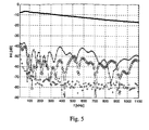
- the 3 transfer functions (measured, estimated via 1-port measurement S 11 , estimated via a 2-port measurement H) match very well.
- An further embodiment of the present invention which is a preferred best mode operation of the invention determines the transfer function using a two-port measurement technique. particularly, preferred is the measurement at the receiver of standard tones transmitted along the transmission line.
- the ITU standards G.9992.1 for asymmetric digital subscriber line transceivers and G.9994.1 for handshake procedures for asymmetric digital subscriber line transceivers describe initialisation routines which require the transmission of periodic signals for channel analysis. This channel analysis may include determination of the transfer function. This directly determined transfer function is then used to determine an optimised model for the transmission line without requiring prior knowledge as to this topology.
- the line lengths and the topology are assumed unknown and the optimisation procedure is used to select a model which gives the best fit as well as providing the length of this line topology.
- Other details of the estimation step are as described in section 1.3.
- a single line of 1500 meters and a homogeneous bridged tap network (section lengths of 900, 600 and 100 meters) were used (cable type 0.5mm).
- the transfer function was meaures using tones at different frequencies only in the downstream band of VDSL.
- the minimised cost functions are shown in table 1.
- Table 1. Minimised Cost functions Estimator: Measurement Single Line Tap Single line 9.1e12 7.6e14 Tap 5.8e14 2.3e13 From the table the minimum values of the cost functions identify the relevant topolgy accurately.
- the estimated lengths were 1500.63 meters for the single line and 900.88/600.56/99.94 for the tap lengths. the agreement is excellent confirming the model.
- FIG 14 is a schematic diagram for describing the methods in accordance with the present invention for estimating at least one crosstalk related parameter of the network.
- a network 50 has a central office 51 comprising a plurality of VDSL transceivers 52, 53 feeding transmission lines 54, 55.
- At the customers premises transceivers 56, 57 terminate the transmission lines 54, 55.
- FEXT from a disturber loop 55 (in the following equation the subscript d relates to the disturber loop) accumulates in a victim loop 54 (in the following equations in the subscript v relates to the victim loop). It is not a requirement of the present invention that loops 54, 55 are the same length.
- Each transmission line 54, 55 will be considered as a pair of twisted cables but the present invention is not limited thereto. There is capacitive and inductive coupling between the wires of this 4-conductor transmission line.
- the parameters of the chosen model can be used in a model of crosstalk related parameters such as FEXT.
- the calculation result is an unbalance function for FEXT CF and NEXT CN.
- Notation in the formulas is consistent with the notation in G.A. Cambell, "Dr. Campbell's Memoranda of 1907 and 1912", The Bell System technical Journal, vol.14, no. 4, pages 553-573, Oct. 1935 ; H. Carvis and T. V. Crater, "Engineering of T1 Carrier System Repeated Lines", The Bell System technical Journal, vol. 42, no. 42, pages 431-486, March 1963 ; A. J. Gibbs and R. Addie, "The Covariance of near End crosstalk and its application to PCM System Engineering in multipair cable", IEEE trans. Comm. vol. 27, no.2, pages 469-477, Feb. 1979 .
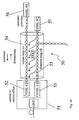
- Figure 15 depicts the coupling between the disturber and the victim loop.
- the disturber loop has 1 bridged tap and hence consists of three line sections. All line sections have the same characteristic impedance and propagation constant. the line lengths are I 1 , I 2 and I 3 .
- the corresponding transfer functions are e - l 1 , e - l 2 and e - l 3 .
- the line is terminated in the characteristic impedance.
- the FEXT transfer function can be used to determine power back-off.
- the PSD of a transmitter is represented as S t (f) as a function of frequency f. This PSD is to be set so that at a receiver no more than a reference PSD S r (f) is obtained.
- the value of S t (f) can be determined by: S r f ⁇ E ⁇ X F 2 k F ⁇ k N ⁇ k FN ⁇ S r ( f )
- S t (f) which guarantees conformance with equation 40 (provided it does not exceed a maximum power allowed for the transmitter) will provide a good equalised FEXT performance of the network.
- the present invention may be implemented on a computing device e.g. a personal computer or a work station which has an input device for loading the details of the network whose capacity is to be estimated, e.g. its topology as well as any other parameters required by the various models and methods defined above in the description as well as in the attached claims.
- the computing device may be in the form of a card mounted microprocessor which may plugged into a network card slot of a telecommunications network element such as the 7300 Alcatel DSL Subscriber Access Multiplexer supplied by Alcatel NV, Antwerp Belgium .
- the computing device is adapted to run software which carries out any of the methods in accordance with the present invention.
- the computer may alternatively be a server which is connected to a data communications transmission means such as the Internet, a Local Area Network or a Wide Area Network.
- a script file including, for example, the details of the topology of the network and/or physical constants relating to the materials used in the construction of the transmission line(s), may be sent from one near location, e.g. terminal, to a remote, i.e. second location, at which the server resides.
- details of the reflectogram or the received results from tone measurements of transfer functions for the relevant network may be sent to the server from the same near location or from another location.
- the server receives all this data and carries out a method in accordance with the present invention and outputs back along the communications line useful data to a near terminal, e.g. a cross-talk related parameter.
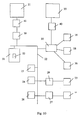
- FIG. 10 is a schematic representation of a computing system which can be utilized in accordance with the methods and systems of the present invention.
- a computer 10 is depicted which may include a video display terminal 14, a data input means such as a keyboard 16, and a graphic user interface indicating means or pointer such as a mouse 18.
- Computer 10 may be implemented as a general purpose computer.
- Computer 10 includes a Central Processing Unit (“CPU”) 15, such as a conventional microprocessor of which a Pentium III processor supplied by Intel Corp. USA is only an example, and a number of other units interconnected via system bus 22.
- the computer 10 includes at least one memory.
- Memory may include any of a variety of data storage devices known to the skilled person such as random-access memory (“RAM”), read-only memory (“ROM”), non-volatile read/write memory such as a hard disc as known to the skilled person.
- RAM random-access memory
- ROM read-only memory
- non-volatile read/write memory such as a hard disc as known to the skilled person.
- computer 10 may further include random-access memory (“RAM”) 24, read-only memory (“ROM”) 26, as well as an optional display adapter 27 for connecting system bus 22 to an optional video display terminal 14, and an optional input/output (I/O) adapter 29 for connecting peripheral devices (e.g., disk and tape drives 23 such as for example a CD-ROM reader) to system bus 22.
- Video display terminal 14 can be the visual output of computer 10, which can be any suitable display device such as a CRT-based video display well-known in the art of computer hardware. However, with a portable or notebook-based computer, video display terminal 14 can be replaced with a LCD-based or a gas plasma-based flat-panel display.
- Computer 10 further includes user interface adapter 30 for connecting a keyboard 16, mouse 18, optional speaker 36, as well as allowing optional physical value inputs from physical value capture devices 40 of an external system 20.
- the devices 40 may be any suitable equipment for capturing physical parameters of the network or parameters of the various models required in the execution of the present invention. These capture devices may also include a stimulus and a measurement device for inputting a test wave and for measuring the response of a network or parts thereof, e.g. a reflectogram or other form of received signal. Additional or alternative devices 41 for capturing physical parameters of an additional or alternative external system 21 may also connected to bus 22 via a communication adapter 39 connecting computer 10 to a data network such as the Internet, an Intranet a Local or Wide Area network (LAN or WAN) or a CAN.
- the term "physical value capture device” can also includes devices which provide values of parameters of a network or networks, e.g. topologies, or for instance a library of candidate networks or candidate network topologies.
- Computer 10 also includes a graphical user interface that resides within a machine-readable media to direct the operation of computer 10. Any suitable machine-readable media may retain the graphical user interface, such as a random access memory (RAM) 24, a read-only memory (ROM) 26, a magnetic diskette, magnetic tape, or optical disk (the last three being located in disk and tape drives 23). Any suitable operating system and associated graphical user interface (e.g. Microsoft Windows) may direct CPU 15.
- computer 10 includes a control program 51 which resides within computer memory storage 52. Control program 51 contains instructions that when executed on CPU 15 carries out the operations described with respect to the methods of the present invention. The instructions may be obtained by writing a computer program in a suitable language such as C or C++ for execution of any of the methods in accordance with the present invention and then compiling the program so that it executes on a computing device.
- FIG. 10 may vary for specific applications.
- peripheral devices such as optical disk media, audio adapters, or chip programming devices, such as PAL or EPROM programming devices well-known in the art of computer hardware, and the like may be utilized in addition to or in place of the hardware already described.
- a computer program product i.e. control program 51 for executing methods in accordance with the present invention comprising instruction means in accordance with the present invention
- the instructions e.g., computer readable code segments in storage 52
- the instructions may be read from storage into RAM 24.
- Execution of sequences of instructions contained in the RAM 24 causes CPU 15 to perform the process steps described herein.
- hard-wired circuitry may be used in place of or in combination with software instructions to implement the invention.
- embodiments of the invention are not limited to any specific combination of hardware circuitry and software. Accordingly, the present invention may take the form of an entirely hardware embodiment, an entirely software embodiment or an embodiment combining software and hardware aspects.
- the present invention may take the form of a data carrier medium (e.g. a computer program product on a computer-readable storage medium) carrying computer-readable program code segments embodied in the medium.
- carrier medium e.g. a computer program product on a computer-readable storage medium
- computer-readable medium refer to any medium that participates in providing instructions to a processor such as CPU 15 for execution.
- Such a medium may take many forms, including but not limited to, non-volatile media, volatile media, and transmission media.
- Non-volatile media include, for example, optical or magnetic disks, such as a CD-ROM or a storage device which is part of mass storage.
- Volatile media includes dynamic memory such as RAM 24.
- Transmission media include coaxial cables, copper wire and fiber optics, including the wires that comprise a bus within a computer, such as bus 22. Transmission media can also take the form of acoustic or light waves, such as those generated during radio wave and infra-red data communications.
- Computer-readable media include, for example a floppy disk, a flexible disk, a hard disk, magnetic tape, or any other magnetic medium, a CD-ROM, any other optical medium, punch cards, paper tapes, any other physical medium with patterns of holes, a RAM, a PROM, an EPROM, a FLASH-EPROM, any other memory chip or cartridge, a carrier wave as described hereafter, or any other medium from which a computer can read.
- the instructions may initially be carried on a magnetic disk of a remote computer.
- the remote computer can load the instructions into its dynamic memory and send the instructions over a telephone line using a modem.
- a modem local to the computer system can receive the data on the telephone line and use an infrared transmitter to convert the data to an infra-red signal.
- An infra-red detector coupled to a bus can receive the data carried in the infra-red signal and place the data on the bus.
- the bus carries data to main memory, from which a processor retrieves and executes the instructions.
- main memory may optionally be stored on a storage device either before or after execution by a processor.
- the instructions can also be transmitted via a carrier wave in a network, such as a LAN, a WAN, or the Internet.
- a network such as a LAN, a WAN, or the Internet.
- computer readable signal bearing media include: recordable type media such as floppy disks and CD ROMs and transmission type media such as digital and analogue communication links which may be used for downloading the computer program product.
- a method in accordance with the present invention will be described with reference to a personal computer.
- a computer program written to carry out the methods of the present invention is started in the usual way. For instance, a pop-up message appears providing an input form for specifying the network topology to be used.
- the possibility for using predefined topologies may be provided, e.g. by allowing selection from a drop-down menu.
- an option may be provided when the topology is not known.
- the program will make use of a set of predefined typical topologies and will attempt to fit a measured reflectogram to each of the models or to fit a measured transfer function to each of the models. The best fit is assumed to represent a topology which is close to the actual topology and is used for the crosstalk-related parameter calculation.
- the reflectogram or the received signals based on tome transmissions may be entered. This may be done by loading from a peripheral device, e.g. from a CD-ROM read by a CD-ROM reader, or by downloading it from mass storage, e.g. from a server located on a LAN or via the Internet.
- the computer may be connected to a suitable reflectogram or other received signal capture device, e.g. via a USB interface, for direct measurement and loading of the reflectogram or other received signals, e.g. from tone measurements.
- the reflectogram may be obtained from a single location in the network, e.g.
- the reflectogram or other received signals will generally be in analogue form and is converted into digital signals by an analogue/digital converter.
- the program then optimizes the coefficients of the parametric model, e.g. by minimizing a cost function relating to a difference between the measured reflectogram and a computed transfer function for the model or between the measured transfer function and a computed transfer function for the relevant model.
- a transfer function and/or a length of a loop of the network is determined. From the selected topology and the length of the loop, knowing the transfer function cross-talk related parameters can be calculated.
- the output of the computer program can be any or all of the following:
Landscapes
- Engineering & Computer Science (AREA)
- Computer Networks & Wireless Communication (AREA)
- Signal Processing (AREA)
- Cable Transmission Systems, Equalization Of Radio And Reduction Of Echo (AREA)
- Measurement Of Resistance Or Impedance (AREA)
- Analysing Materials By The Use Of Radiation (AREA)
- Monitoring And Testing Of Transmission In General (AREA)
- Data Exchanges In Wide-Area Networks (AREA)
Abstract
Description
- The present invention relates to simulation methods for telecommunications networks and to telecommunications networks themselves having a plurality of transmission lines with receivers and transmitters connected by some form of communications channel which is subject to crosstalk. The present invention is especially useful for the prediction and adjustment of network parameters such as a transmission powers, in particular for use in xDSL networks as well as for simulating such networks.
- The acronym xDSL stands for the family of Digital Subscriber Line technologies, which allow high-speed access to the Internet and multimedia services over the local loop, which connects the CP (customer premises) to the CO (central office), that is over simple twisted pair cables. An xDSL transceiver at the CO communicates with an xDSL transceiver at the CP over the local loop.
- Since decades the local loop, which is a transmission line consisting of two twisted copper wires, also called unshielded twisted pair (UTP), has given the customer access to POTS (Plain Old Telephony Service). The POTS signal, transmitted over the local loop, is analog and contained in the frequency band up to 4 kHz, which corresponds to the spectral content of speech.
- xDSL exploits the frequency band above 4 kHz up to several MHz, which is not used by POTS. However as the legacy local loops have been engineered for voice-band transmission, there are no guarantees about the quality of the local loop with respect to transmission in this higher frequency band. The signal-to-noise ratio (SNR) as a function of the frequency at the receiver at the CP, respectively the CO, for the downstream transmission (from the CO to the CP), respectively the upstream transmission (from the CP to the CO) plays an important role. The SNR at the receiver at the CP, respectively the CO, is determined as a function of the frequency by the transfer function of the loop between the CO and the CP and the noise PSD (Power Spectral Density) at the CP, respectively the CO given the PSD of the transmitted signal at the CO, respectively the CP.


- In general the local loop consists of a network of transmission lines. Every line in the network is a UTP characterized by its length and type. The line type specifies the cross-sectional geometrical dimensions, such as the wire diameter (also called wire gauge), and the material physical constants, such as the electrical permittivity of the dielectric separating the 2 copper wires. The most used wire diameters are 0.4 mm, 0.5 mm, and 0.6 mm. Polyethylene (PE) is the most occurring insulator but other materials are also used such as paper and PVC.
- The network topology of the local loop is limited to a tree structure. The simplest topology is a single line. The magnitude of the transfer function reflects the attenuation of the line, which gets worse with increasing frequency and line length. Another topology that exists for long loops is a cascade of 2 or more lines with increasing wire diameter from the CO to the CP. For this topology reflections are caused by the change of the wire diameter at the splices connecting 2 lines. A topology that is also frequently encountered, especially in the USA, is a loop with 1, 2 or more bridged taps. A bridged tap is an open-ended line spliced to the main line. Reflections appear for this topology at the splice connecting the bridged tap to the loop and at the open end of the bridged tap. Reflections have a negative impact on the transfer function, because they interfere with the signal propagating along the direct path. For those frequencies for which the interference is destructive, the magnitude of the transfer function reduces. Such reductions rarely appear in the voice band because the bridged taps are usually not too long.
- As the twisted pairs constituting the local loop are unshielded, external electromagnetic waves may couple into the loop and propagate towards the CO and the CP causing noise at the receiver. The electromagnetic coupling is reduced by the twisting of the 2 wires, because adjacent segments of the twisted pair experience electromagnetic waves with opposite polarity. In addition the twisting improves the balance of the line. A line is balanced when the 2 conductors have an equal impedance towards the earth. The balancing of the line prevents a common-mode signal from transforming into a differential-mode signal. In the case of a common-mode signal the 2 wires carry equal currents and the return path of the current is the ground. For a differential-mode signal the 2 wires carry opposite currents (out of phase currents). Electromagnetic waves may couple into the line because of imperfect twisting, and the common-mode signal that they cause, may transform into a differential-mode signal because of imperfect balancing, which is correlated with the twisting. Balance decreases with increasing frequency.
- The noise is divided into 2 different types according to the origin of the external electromagnetic waves coupling into the loop. The first type of noise is crosstalk, which is the electromagnetic coupling between twisted pairs in the same cable or between cables. The cables leaving the CO contain thousands of twisted pairs. The closer to the CP the less pairs there are present in a cable. A difference is made between near-end crosstalk (NEXT) and far-end crosstalk (FEXT). The transmitters at the CO, respectively CP, are the source of NEXT for the near-end receivers at the CO, respectively the CP, and are the source of FEXT for the far-end receivers at the CP, respectively the CO. In general crosstalk gets worse with increasing frequency.
- A second type of noise is radio-frequency interference (RFI), which is caused by radio waves coupling into the local loop, that acts as an antenna, especially if there are aerial lines. There are 2 major sources of radio waves in the frequency band of xDSL namely AM radio and amateur radio.
- Hence, the local loop has several impairments for transmission in the frequency band of xDSL, which are not present for voice-band transmission.
- Various proposals have been made to calculate or estimate FEXT at a port of a transmission line. The methods of T1.413 [ANSI, 1995] assume that all loops are symmetrical, i.e. that the receivers can be replaced by the transmitters and vice versa. This may be unreasonable because:
- a) It is very unlikely that the loop under test and an interfering loop will have the same tolopogies, e.g. the same number of bridge taps. A bridge tap in only the test loop will reduce performance, a bridge only in the interfering loop will improve performance.
- b) Since most bridge taps are closer to the CP than the CO this is most important in the upstream direction. Not all CP's are the same distance away. Short cables will have a serious affect on long cables at the CO.
- In the early 1980's many hundreds of thousands of measurements of crosstalk were made; mostly on 50 pair binder groups that are used for interexchange transmission of T1 and T2 signals. These included pair-to-pair measurements and pairs to one measurements. From these measurements cumulative probability density functions were plotted and some worst-case probabilities estimated. Analysis of this type has resulted in various empirical formulae which are supposed to provide reasonable estimations. However, such empirical formulae are unsatisfactory especially when systems are considered that differ greatly from those from which the empirical results have been obtained. Also when applying xDSL to legacy networks the topology of the loops is often not known so that no assessment can be made as to whether the model used is suitable.
- Upstream power backoff (UPBO) guarantees spectral compatibility between long and short loops that are operating in the same cable binder. UPBO is a method by which the upstream power spectrum density (PSDtransmit) being generated by a transmitter on a short disturber line is controlled in order to limit excessive crosstalk into neighbouring lines. The crosstalk measured at the line terminator of the victim loop impacts on the bit rate performance of the victim loop. A current method of UPBO is based on an estimation of the length of the loop. The electrical length is obtained by comparing the attenution of the loop under consideration with the attenuation of a reference loop. This reference loop consists of a single line segment. The PSDtransmit is determined by (PSDref) /|TF| where TF is the transfer function of the disturber loop which is a function of the electrical length of this loop. This method is only useful for single segment loops, i.e. with no bridge tap, no mixed wire gauges nor imperfect terminations. Particualrly, bridge taps can result in imperfect performance as indicated above.
- A system and methodology for qualifying a twisted pair copper loop for digital subscriber loop services are described in the US Patent with
Patent N° US 6,292,539 with Date of patent dd. Sept. 1 8, 2001. Herein it is described that the system automatically queries telecommunications provider database records and/or requests measurements from network switching equipment or testing systems to obtain data regarding the twisted pair copper loop, such as loop length, electrical characteristics, and other loop topology characteristics such as wire qauge, the presence of load coils, and the presence of bridge taps. The system determines which digital subscriber loop services are available for the copper loop based on the combination of all data obtained. The system may be implemented in part as an expert system with a knowledge base qualification rules used in the decision-making process. - It is an object of the present invention to provide a method and apparatus for the upstream backoff of combinations of transmission lines which are more accurate and/or flexible than conventional methods and apparatus.
- It is a further object of the present invention to provide a method and apparatus for simulation of crostalk-related parameters in transmission lines which are more accurate and/or flexible than conventional methods and apparatus.
- An aspect of the present invention may be described as a method and apparatus for modeling a network comprising a plurality of transmission lines, the method and system being adapted to measure loop parameters of a transmission line to provide measured loop parameters, determine a topology of the first transmission line by analysing the measured loop parameters with reference to at least a one model of a plurality of models for transmission lines of different topologies, select a further model for estimating crosstalk related parameters based on the determined topology, and estimate at least one crosstalk related parameter based on the determined topolgy and the selected further model. The method may include determining a transmit power spectrum for a transmitter on the network in accordance with the estimated crosstalk related parameter. The crosstalk related parameter may be a transfer function for at least one of FEXT, NEXT, alien-NEXT, alien-FEXT, EL-FEXT, EL-NEXT, self-NEXT, self-FEXT.
The measuring step may include carrying out a two-port measurement of the transmission line by inputting an excitation signal at one port of the transmission line and measuring the received signal at another port of the transmission line; deriving from the received signal a transfer function of the transmission line; generating a 2-port parametric model of the transmission line; and optimising values of the parameters of the 2-port parametric model by reducing the difference between the derived transfer function and a transfer function calculated from the at least one model. Alternatively, the measuring step may comprise carrying out a 1 port measurement on the network by inputting an excitation signal at one port of the network and recording the results at the port; generating a 1 port parametric model of the network; and optimising the values of the parameters of the 1 port parametric model by reducing the difference between the results of the measurement step and results calculated using the 1-port parametric model and the excitation signal. The reducing step may be carried out by minimizing a cost function by adapting the values of the parameters of the relevant parametric model, the cost function representing a quantification of the difference. The method may comprise the step of determining a length of the transmission line as an output of the optimising step. - In one aspect of the present invention an estimation of the end-to-end transfer function of at least one transmission line is based on measurements at one termination location thereof only or at two or more locations. The invention includes the characterization of the transmission line even though its length and topology is unknown. This characterisation can be used to predict the transfer function for the line. Alternatively, the transfer function may be measured directly, e.g. by using tones emitted from modems at each end of the transmission line. In order to characterize the transmission line an excitation signal is generated at one or more termination locations thereof, e.g. at a central-office end of a local loop depending on which method is used to obtain the transfer function. For the single port measurement method a response signal is measured at the same location as the excitation signal is generated. This excitation signal corresponds to the incident wave and the response signal to the reflected wave. The latter is also called reflectogram. This measurement procedure is called reflectometry (time-domain reflectometry, or TDR, if the signals are measured in the time domain). The ratio of the reflected wave and the incident wave is defined as the scattering parameter S11 (also called reflection factor in the case of a 1-port). So the scattering parameter S11 of a certain transmission line describes how that line responds in terms of a reflected wave, if it is excited with a certain incident wave. The complete model of the line considered as a 2-port consists of the 4 scattering parameters S11, S21, S12, and S22. The transfer function is related to the scattering parameter S21.
- A transmission loop, e.g. a local loop usually consists of a network of transmission lines connecting the customer premises to the central office. The network topology is limited to a tree structure. Every line in the network is characterized by its length and type. The line type specifies the cross-sectional geometrical dimensions and the material constants.
- If two port measurements are used then the excitation signals are entered at each end of the transmission line separately and the received signal measured at the other end.
- The above methods may include a step of reducing the difference between measured values (two port or one port) and the model by:
- quantifying said difference as a cost function; and
- iteratively minimizing said cost function by adapting parameter values of said frequency domain parametric model. The cost function may be a maximum likelihood estimator or a Bayesian estimator.
- a message that the at least one transmission line cannot be modeled within a predetermined accuracy for the parametric model or for the model of crosstalk parameters, e.g. FEXT
- a necessary power back-off at a transmitter;
- a PSD at a receiver or a PSD of a transmitter.
- In the above methods the at least one transmission line can be a local loop of an access network.
- The present invention may also provide a system for modeling a network, comprising: means for measuring loop parameters of first transmission line to provide measured loop parameters,
means for determining a topology of the first transmission line by analysing the measured loop parameters with reference to at least a one model of a plurality of models for transmission lines of different topologies, means for selecting a further model for estimating crosstalk related parameters based on the determined topology, and means for estimating at least one crosstalk related parameter based on the determined topolgy and the selected further model. The system may comprise means for determining a transmit power spectrum for a transmitter on the network in accordance with the estimated crosstalk related parameter.The crosstalk related parameter may be a transfer function for at least one of FEXT, NEXT, alien-NEXT, alien-FEXT, EL-FEXT, EL-NEXT, self-NEXT, self-FEXT. The means for measuring may include means for carrying out a two-port measurement of the transmission line by inputting an excitation signal at one port of the transmission line and measuring the received signal at another port of the transmission line, further comprising means for deriving from the received signal a transfer function of the transmission line; means for generating a 2-port parametric model of the transmission line; and means for optimising values of the parameters of the 2-port parametric model by reducing the difference between the derived transfer function and a transfer function calculated from the at least one model. The means for measuring may comprise means for carrying out a 1 port measurement on the network by inputting an excitation signal at one port of the network and recording the results at the port; further comprising: means for generating a 1 port parametric model of the network; and means for optimising the values of the parameters of the 1 port parametric model by reducing the difference between the results of the measurement step and results calculated using the 1-port parametric model and the excitation signal. The means for optimising may include means for reducing the difference by minimizing a cost function by adapting the values of the parameters of the relevant parametric model, the cost function representing a quantification of the difference. The means for optimising may include means for determining a length of the transmission line. - In the above systems may inclmude processing means including means for estimating a transfer function of said at least one transmission line.
- In the above systems, the means for reducing the difference may include:
- means for quantifying said difference as a cost function; and
- means for iteratively minimizing said cost function by adapting parameter values of said frequency domain parametric model.
- The above systems may include means for outputting at least one of:
- a message that the at least one transmission line cannot be modeled within a predetermined accuracy;
- a power back-off to be set at a transmitter;
- a PSD at a receiver.
- The above systems for modeling may be included in a central office system of a telecommunications network.
- The present invention also includes a data carrier medium carrying one or more computer readable code segments for controlling a processing device to carry out any method in accordance with the present invention.
- The present invention also includes a computer program product for execution of any of the methods in accordance with the present invention on a computer system.
- The present invention also includes a method for modelling a representation of network, said method comprising:
- transmitting a description of the network from a near location to a remote computing system via a telecommunications network,
- executing on the remote computer system any of the methods of the present invention, and
- transmitting to a near location information relating to crosstalk in the network.
-
-
Fig. 1 shows a transmission line model of a single loop. -
Fig. 2 shows a transmission line model of a bridge tapped loop. -
Fig. 3 shows a transmission line model of a loop of two cascaded lines. -
Fig. 4 shows measurements and estimated values of the scattering parameter S11 versus frequency using embodiments of the present invention for a single line. -
Fig. 5 shows measurements and estimated values of the transfer function H versus frequency using embodiments of the present invention for a single line. -
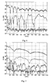
Fig. 6 shows measurements and estimated values of the scattering parameter S11 versus frequency using embodiments of the present invention for two cascaded lines. -
Fig. 7 shows measurements and estimated values of the transfer function H versus frequency using embodiments of the present invention for two cascaded lines. -
Fig. 8 shows measurements and estimated values of the scattering parameter S11 versus frequency using embodiments of the present invention for a bridge tapped line. -
Fig. 9 shows measurements and estimated values of the transfer function H versus frequency using embodiments of the present invention for a bridge tapped line. -
Fig. 10 is a schematic representation of a computing device which can be used with the present invention. -
Fig. 11 is a schematic representation of a method flow diagram of an embodiment of the present invention. -
Fig. 12 shows measurements and estimated values of the transfer function TF versus frequency using embodiments of the present invention for a single line. -
Fig. 13 shows measurements and estimated values of the transfer function TF versus frequency using embodiments of the present invention for a bridge tapped line -
Fig. 14 is a schematic representation of a network showing FEXT interference on a victim line from a disturber line. -
Fig. 15 is a schematic representation of a part of a network comprising a victim and a disturber loop. - The present invention will be described with reference to certain embodiments and drawings but the present invention is not limited thereto but only by the claims. In the following embodiments of the present invention will be described by a parametric model detailed for a limited number of network topologies but this does not limit the applicability of the invention. The skilled person will appreciate that the present invention may be extended to other topologies and to other materials once the principles of the present invention have been understood. All such additional topologies are included within the scope of the present invention. Also in the description a twisted pair transmission line model is given. However the invention is not limited to this model and is not limited to twisted pair cables as transmission lines. The application of the present invention is not limited in this respect and it can be used for symmetric or asymmetric lines, for example in the case of coaxial cables, optical fibers, etc. and even in the case of a general 2-port network. Further, the invention will mainly be described with reference to FEXT but the present invention is not limited thereto but can be applied to other forms of crosstalk such as NEXT, alien-NEXT (influences by electromagnetic interference from outside the network), alien-FEXT, EL-FEXT, EL-NEXT, self-NEXT, self-FEXT. A general reference book for xDSL is "ADSL, VDSL and multicarrier modulation", by John Bingham, Wiley, 2000. The following references may also be found useful for understanding the present invention.
- [1] P. Boets, "Frequency Domain Identification of Transmission Lines from Time Domain Measurements", Ph-D. Thesis, Vrije Universiteit Brussel, Dept. ELEC, . This document is incorporated by reference in its totality.
- [2] P. Boets, M. Zekri, L. Van Biesen, T. Bostoen, and T. Pollet, "On the Identification of Cables for Metallic Access Networks," in Proc. IMTC, 2001, incorporated by reference in its totality.
- [3] D. M. Pozar, Microwave Engineering, 2nd ed. New York: John Wiley & Sons, 1998.
- The present invention may be summarised as follows. One or more measurements of a transmission loop of a communications network are made. These measurements are compared with one or more parametric models of predefined loop topologies. The parameters of each topology model are optimised to give the best fit to the measurement results. This optimisation may be done by minimising or maximising a cost function. From this analysis a best fit topology is determined, i.e. a topology is chosen which corresponds to the best fit model to the measured results. Parameters available from the parametric model are fed into a parametric crosstalk model of the same topology as the best fit topology. This crosstalk model is used to obtain a crosstalk-related parameter of the network, e.g. FEXT, NEXT, self-FEXT, self-NEXT, alien-NEXT, alien-FEXT, EL-FEXT or EL-NEXT, a PSD at a receiver, a power back-off to obtain a certain PSD at a receiver. A step in the above method is obtaining the transfer function of a loop. This can be obtained by two-port or on-port measurements in accordance with separate embodiments of the present invention.
- In accordance with an embodiment of the present invention, given a specified or assumed network topology, a 1-port parametric model for the S11 scattering parameter of the network is derived from the models for individual line sections of the network or based on an assumed model. In an S11 scattering parameter model the parameters of the individual lines appear as independently identifiable parameters. It is then possible to model the loop completely by only measuring the scattering parameter S11. The unknown parameters have to be estimated by a further optimization routine. The optimized parameters are used in a 2-port model of the network for further analysis of the network.
- Accordingly, each line in a network is fully characterized by a parametric model, which consists of the characteristic impedance and the transfer function of the line as a function of the frequency and a number of unknown parameters. Several line models are available. A model based on electromagnetic theory is one of the most useful for the line characterization. This model is based on the 4 primary transmission line parameters, which are resistance, inductance, conductance, and capacitance, as a function of the frequency and a number of parameters related to the cross-sectional geometrical dimensions and material constants. These latter parameters are considered to be unknown. In the following, it will be assumed that the transmission line comprises twisted pair cables. For other cable types, equivalent models may be selected. For twisted pair cable, the electromagnetic model assumes that the wire for the local loop comprises 2 cylindrical conductors with the same diameter immersed in a homogeneous dielectric. It allows for the skin effect and the proximity effect (up to 2 terms in the Fourier series solution). It contains 5 independently identifiable parameters, which are related to the cross-sectional geometric dimensions and material constants of the components of the twisted pair cables. The electrical permittivity of the dielectric is considered to be independent of the frequency in this model and the conductance is neglected, which are good approximations for polyethylene (PE). This line model will be called VUB1.
- Parameter estimation is an important part of characterization of a loop in accordance with the present invention. In accordance with an embodiment of the present invention the difference between measured values for a loop and the modeled values for the same loop is reduced by appropriate selection/determination of the unknown parameters. For example, a cost function may be introduced which quantifies the deviation between the measured values (reflectogram) and the result of modeling the scattering parameter S11 of the loop as a function of the model parameters. In order to match the model as well as possible to the measured values the cost function is minimized as a function of the model parameters. The values of the model parameters corresponding to this minimum are the estimated values of the parameters. The lower limit of the variance of the estimated parameters may given by any suitable method, e.g. by the Cramer-Rao lower bound. The cost function is also called an estimator, because it determines the parameter estimation completely. Several estimators are available. The maximum likelihood estimator (MLE) is preferred because it is consistent, asymptotically unbiased, asymptotically normally distributed, and asymptotically efficient under certain noise assumptions. In addition it is robust. It has such good properties because it takes the noise in the measurement into account. This means of course that this noise has to be measured. The characterization is typically performed in the frequency domain and the measurement in the time domain but the present invention is not limited thereto. Measurements and characterization may be performed in either the time domain or the frequency domain.
- The minimum of the cost function as a function of the model parameters is found by means of an optimization algorithm. Typically, this optimization algorithm will be iterative There are several known optimization routines which may be used. The Levenberg-Marquardt (LM) method is preferred. It combines the Gauss-Newton and gradient descent procedures. The Gauss-Newton method is very fast, because it makes use of second-order derivatives, but it does not always converge. This problem of convergence is solved in the Levenberg-Marquardt algorithm by addition of the gradient descent method. The Levenberg-Marquardt algorithm only searches for a local minimum. In order to find the global minimimum, the initial values of the model parameters are preferably chosen to be close enough to the exact values, which correspond to the global minimum of the cost function so that the optimization does not become trapped in a local mimimum. As the estimated parameters are available for all the individual lines, the loop is completely modeled and the estimated transfer function can be calculated.
- In accordance with an embodiment of the present invention, a suitable optimization is based on a S11 scattering parameter measurement, an MLE cost function and an LM optimization algorithm. The S11 scattering parameter model depends on the network topology and the model for the individual line sections. For every different network topology and line model there is a different S11 scattering parameter model. This model has to be calculated. Independently identifiable parameters have to be determined. The derivatives of the model to its parameters have to be computed, because they are needed for the Jacobian in the LM optimization algorithm.
- This has been illustrated for 3 different loop topologies: a single line, a cascade of 2 lines, and a loop with 1 derivation, also called bridged tap, but the skilled person will appreciate after having understood the present invention that it may be extended to other topologies. For all these loop topologies the assumption has been made that the loop is open at the customer-premises end, which is a fair approximation of a phone set that is on-hook. For the loop with a bridged tap an additional assumption is that all the individual lines are of the same type. These 3 loop topologies have been chosen to cover all the different causes for reflections in a loop: the mismatch between the generator impedance and the characteristic impedance of the line connected to it, the mismatch between the load impedance and the characteristic impedance of the line connected to it, the mismatch between 2 lines with a different characteristic impedance connected to each other, and the mismatch due to the connection of a derivation.
- When the topology of a loop is unknown an alternative method in accordance with an embodiment of the present invention tries each one of a series of well known topologies and makes an optimization of the unknown parameters for each topology by comparison with the reflectogram. The topology which appears to give the best fit with the reflectogram may then taken as the best fit topology for the calculation of the network capacity.
- A basic methodology in accordance with the present invention will be described with reference to
Fig. 11 . Firstly a 1-portparametric model 2 having a finite number of coefficients whose values need to be optimised is generated instep 1 for a network based on an actual or assumedtopolgy 3 for the network. Then a 1-port measurement 4 is carried out instep 5 on the network to be analysed. For example, a measurement of the scattering parameter S11 may be carried out, but the present invention is not limited thereto - the input impedance Zin could equally well be used. This measurement is used to do the parameter optimisation of the 1-port model 6 of the network in step 7. Then these estimated parameters 9 can be included within a 2-portparametric model 10 for the access network based on a transmission line model for every line segment to compute the estimated transfer function H in step 8. For the purposes of validation only this end-to-end transfer function can be validated with the measured transfer function (see later) and the transfer function estimated directly via the transfer function measurement, however, this is only for validation purposes. - The present invention is not limited to access networks of telephone networks, it can be used for any medium used for transmission where there is a transmitter - medium - receiver structure. To identify the medium, 1 port measurements at transmitter or receiver side can be made and these used to optimisze a parametric 1-port model for the medium. The parametric model preferably has a limited set of parameters. The parameters of the transmission medium model are optimised and then used to determine a 2-port model for the network. The transmission medium could be any one suitable for a coimmunications system, e.g. a network of twisted pair lines, coaxial lines, optical fibers, the air interface of a mobile teleocmmunications network.
- In accordance with embodiments of the present invention a transmission line or a combination or network of transmission lines is modelled by a parametric model having a finite number of coefficients to be determined, e.g. 5 coefficients a1 to a5 for each "basic transmission line" or transmission line primitive. Such a transmission line primitive can comprise a twisted pair cable such as is used conventionally for the local loop of a public telephone system or, for instance, a twisted pair connection between two network devices on a Local Area Network. To model a network of transmission lines, each transmission line primitive is represented by the above parametric model - that is the network is modeled by a set of individual parametric models, one of each transmission line primitive and each having a finite number of coefficients to be determined. Some of the coefficients (e.g. a1 to a5 ) may be estimated initially by calculating an initial value based on characteristics of the relevant transmission line, e.g. physical constants of materials used in the connecting cable forming the transmission line. Other coefficients may be selected, e.g. a4., however it is preferred if these coefficients are also determined so as to bring the initial model close to the optimized one. Knowledge of the actual topology of the network or of a finite number of topologies which the network may have can be used to set up the parametric model.
- In a further step the reflectogram of the network is measured experimentally from one access point or "port" of the network. To record the reflectogram a suitable test wave or pulse is entered at the relevant port and reflected waves measured at the port. This reflectogram is preferably stored in a manner that allows manipulation of the reflectogram within a digital computing device, e.g. the reflectogram may be converted to digital signals using an analogue to digital converter. In a next step the finite number of coefficients of the paramteric model are optimized so as to give a close (or at least a closer fit than the initial values) between a characteristic of the network as modeled and the reflectogram. This comparison may be done in the time domain or the frequency domain. In the following only a comparison in the frequency domain will be described. For example, an optimization routine may be used to optimize the coefficients of the parametric model. The optimization may be done with respect to a cost function. That is, the goodness of fit between the reflectogram and the results predicted by the parametric model (e.g. a difference) may be represented as a quantitative value, and the coefficients may be optimized with reference to this value. For instance, this value may be maximized or minimized depending on whether the chosen value is a large or small value, respectively when there is a good fit.
- One problem with such an optimization is that the routine may stop in a local minimum or maximum and not an absolute one. To avoid or reduce the frequency of this problem the present invention makes use of a quasi-realistic model of the network so that there is some correlation between at least certain coefficients of the parametric model and physical constants of the network. By this means at least some of initial values of the parameters should be close to their final optimized ones and therefore there is less chance that the optimization routine lands in a local minimum. This is a significant advantage of the present invention compared with fully heuristic or pragmatic models for which initial values cannot be calculated reliably from network materials and topologies.
- Finally, the optimized parameters may be used in a 2-port parametric model of the network to determine crosstalk-related parameters as explained above.
- In the following, a non-limiting number of models of useful topologies for local loops of telephone systems will be described.
- The following equations may be used for describing a basic parametric model in accordance with an embodiment of the present invention for an unshielded twisted pair transmission line. This basic parametric model will be used to construct more complex models of networks which can be described by a combination of basic parametric models.


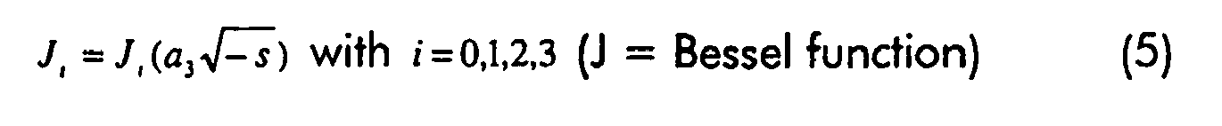


transmission line 
- In this model there are five coefficients which need to be optimized with respect to a measured reflectogram. The coefficients to be determined (a1 to a5 ) may be given initial values in accordance with:


- This transmission line model for twisted pair is based on electromagnetic theory, so it is physical, white-box model (as opposed to black box), that contains as much a priori knowledge as possible. The model includes the skin effect and proximity effect (up to 2 terms of the series solution) and is considered to be suitable for the best mode of operation of the present invention for twisted pair cables. The present invention is not however, limited to this method.
- In the following the use of the basic parametric model will be described with reference to a limited number of useful network topologies.
-
Figure 1 depicts an equivalent electrical circuit of an access network consisting of a single line. Initial values of five parameters, a 1 a 2 a 3 a 4 a 5, of the basic parametric model need to be determined and then optimized. The aim of the modelling exercise is to obtain an expression for S11 (1-port model, used for the parameter estimation) and H, the transfer function (2-port model, needed for capacity estimation and validation).


- Zl = ∞, ρl = 1, (assumption of an open-circuited end of the transmission line, e.g. at the customer premises of a local loop)
- Z ref1 = Zg = 100 Ω
- The transfer function under consideration starts at the beginning of the line and ends at the load (no generator), the transmit PSD (power spectral density) mask is defined at the location of V1 in
Fig. 1 , not at the location of Vg. -
Figure 2 depicts an equivalent electrical circuit of an access network consisting of a loop with a bridge tap. Initial values of seven parameters, a 1 a 2 a 3 a 4 a 5 a 6 a 7 of the parametric model need to be determined and then optimized. The aim of the modeling exercise is to obtain an expression for S11, the scattering function and H, the transfer function.

The following equation defines for a 1-port model the scattering parameter S11:
-

-
Figure 3 depicts an equivalent electrical circuit of an access network consisting of a cascade of two lines. Initial values of ten parameters a 11 a 21 a 31 a 41 a 51 a 12 a 22 a 32 a 42 a 52 of the parametric model need to be determined and then optimized. The aim of the modeling exercise is to obtain an expression for S11, the scattering function and H, the transfer function. Zl = ∞, ρ l =1, (assumption open-circuit at the end)

- In the following one cost function will be described for use in optimizing the parameters of the parametric model, but the present invention is not limited thereto. It is called maximum likelihood for the output error model. This type of cost function has useful properties such as the fact that estimated parameters are not biased,

- M = number of frequency samples
- N = number of parameters
- This first cost function in S11 is important for the general method in accordance with the present invention.
- The optimization of parameters is carried out by minimizing a difference represented by the cost function. The preferred minimizer is from Levenbergh-Marquardt but the present invention is not limited to this type of optimization algorithm, nor to any parrticular values for the starting values.
- As an example, the following starting values may be selected:
- a =0.25×10⁻³ mm
- D =1×10⁻³ mm
- σ = 5.8×10⁷ S/m assumed for copper conductors.
- µ = µ0 for PE insulated cables
- ε = 2.26 ε0 for PE insulated cables
- Lext = mu/(2*pi)log(D^2/radius^2);
- C = 1/Lext*epsilon*mu;
- These are the settings used for the network analyzer measurements for determining H.
- In the measurement step the reflectogram of the network is measured for a specific excitation signal. A Hewlett Packard Network Analyzer type HP4195A was used with a start frequency of 3*4.3125=12.9375 kHz (tone 3) and a stop frequency of 1.104000 MHz (tone 256). The RBW was 100 Hz,
sweep time 2 min, and 401 points were recorded. Four measurements were performed of S11 and H in each case to be able compute mean and variance values. These latter values are used as weighting factors in the MLE cost function (see equation 26) - The transmission lines used were cables, e.g. as supplied by Belgacom (Belgium), having a conductor diameter of 0.5 mm, a PE insulation, and 20 pairs in the form of quads; as supplied by BT (UK), having a conductor size of 0.5 mm, insulation of PE, 20 pairs; as supplied by FT (France), having conductor size of 0,4 mm, PE insulation, 8 pairs, quads. the North Hill balance was 50 Ohm to 135 Ohm
- Only the magnitude is shown, although the phase has been estimated as well. The magnitude is however most important for the capacity estimation
- The results are shown for 3 topologies, but the patent is not limited to these 3 topologies.
LEGEND for graphs inFigs. 4 ,6 ,8 showing S11 on the y axis is : - . (dotted) : measured values as shown in upper portion of figures
- - (full line): estimation as shown in upper portion of figures
- -x- (full line, x): error as shown in the middle of the figures
- -+- (full line for
Figures 6 and8 only, +): 95 % confidence bound as shown in lower protion of the figures - . (dotted) : measured values as shown in upper portion of figures
- - (full line): estimation via S11 (generally so close to the dots that it cannot be distinguished from these at this scale)
- -- (dashed line in
Figures 7 and9 ): estimation via H (generally so close to the dots that it cannot be distinguished from these at this scale) - -x- (full line, x): error in the estimation via S11 in the middle of the figures
- -o- (dashed line in
Figure 5 , full line inFigures 7 and9 , o): error in the estimation via H in the middle of the figures - -+- (full line only in
Figures 7 and9 , +): 95 % confidence bound in the lower portion of the figures - In
Fig. 4 the results for the scattering factor S11, both model and measurement and inFig. 5 for the transfer function H for a single line, both measurement and model are shown. - In
Fig. 6 the results for the scattering factor S11, both model and measurement and inFig. 7 for the transfer function H, both measurement and model are shown. - All segments of cable were BT cable with conductor size of 0.5 mm, first segment was 900 m, second segment 700 m and bridged tap 200 m.
- In
Fig. 8 the results for the scattering factor S11, both model and measurement and inFig. 9 for the transfer function H, both measurement and model are shown. - A BT cable of 500 m and conductor size 0.5 mm was cascaded with an FT cable of 400m with a conductor size of 0.4 mm.
For all the 3 topologies it is clear that the 3 transfer functions (measured, estimated via 1-port measurement S11, estimated via a 2-port measurement H) match very well. - An further embodiment of the present invention which is a preferred best mode operation of the invention determines the transfer function using a two-port measurement technique. particularly, preferred is the measurement at the receiver of standard tones transmitted along the transmission line. The ITU standards G.9992.1 for asymmetric digital subscriber line transceivers and G.9994.1 for handshake procedures for asymmetric digital subscriber line transceivers describe initialisation routines which require the transmission of periodic signals for channel analysis. This channel analysis may include determination of the transfer function. This directly determined transfer function is then used to determine an optimised model for the transmission line without requiring prior knowledge as to this topology.
- The same parametric models are used as described in section 1.1 except that now the transfer function has been measured directly and so the model must be optimised based on these measurements and not on the scattering function determined from a reflectogram. In particular, the transfer function as defined in
equations 19, 23 and 25 are used for the optimisation procedure. - The same estimators are used as in section 1.3 above except that
equation 26 has to be modified to optimise on the measured transfer function:
- A single line of 1500 meters and a homogeneous bridged tap network (section lengths of 900, 600 and 100 meters) were used (cable type 0.5mm). The transfer function was meaures using tones at different frequencies only in the downstream band of VDSL. The minimised cost functions are shown in table 1.
Table 1. Minimised Cost functions Estimator: Measurement Single Line Tap Single line 9.1e12 7.6e14 Tap 5.8e14 2.3e13 - A comparison of the estimated and measured transfer functions for the single line and the tap is given in
figures 12 and 13 respectively. -
Figure 14 is a schematic diagram for describing the methods in accordance with the present invention for estimating at least one crosstalk related parameter of the network. Anetwork 50 has acentral office 51 comprising a plurality ofVDSL transceivers feeding transmission lines customers premises transceivers transmission lines loops transmission line - Once the topology and length of the loop has been determined by any of the above methods, the parameters of the chosen model can be used in a model of crosstalk related parameters such as FEXT. In the following the calculation result is an unbalance function for FEXT CF and NEXT CN. Notation in the formulas is consistent with the notation in G.A. Cambell, "Dr. Campbell's Memoranda of 1907 and 1912", The Bell System technical Journal, vol.14, no. 4, pages 553-573, Oct. 1935; H. Carvis and T. V. Crater, "Engineering of T1 Carrier System Repeated Lines", The Bell System technical Journal, vol. 42, no. 42, pages 431-486, March 1963; A. J. Gibbs and R. Addie, "The Covariance of near End crosstalk and its application to PCM System Engineering in multipair cable", IEEE trans. Comm. vol. 27, no.2, pages 469-477, Feb. 1979.
-
Figure 15 depicts the coupling between the disturber and the victim loop. The generator has a voltage Vg and internal impedance Zg = Z0, with Z0 being the characteristic impedance of the loop. The disturber loop has 1 bridged tap and hence consists of three line sections. All line sections have the same characteristic impedance and propagation constant. the line lengths are I 1, I 2 and I 3. The corresponding transfer functions are e-l1 , e-l2 and e-l3 .The line is terminated in the characteristic impedance. For simplicity certain assumptions may be made in the model about CF(z) and CN(z): - 1. real and constant (independent of frequency)
- 2. stochastic variables normally distributed
- 3. E[CF(z)] = 0
- 4. E[CF(z)CF(z')] = kF (z-z')

- The calculation of the power FEXT transfer function (for a certain pair-pair combination) is as follows.
- The expectation value of the FEXT power trasfer function in dependence on the constans kF, kN and kFN is given by:


- The FEXT transfer function can be used to determine power back-off. The PSD of a transmitter is represented as St(f) as a function of frequency f. This PSD is to be set so that at a receiver no more than a reference PSD Sr(f) is obtained. The value of St(f) can be determined by:

- The present invention may be implemented on a computing device e.g. a personal computer or a work station which has an input device for loading the details of the network whose capacity is to be estimated, e.g. its topology as well as any other parameters required by the various models and methods defined above in the description as well as in the attached claims. The computing device may be in the form of a card mounted microprocessor which may plugged into a network card slot of a telecommunications network element such as the 7300 Alcatel DSL Subscriber Access Multiplexer supplied by Alcatel NV, Antwerp Belgium . The computing device is adapted to run software which carries out any of the methods in accordance with the present invention. The computer may alternatively be a server which is connected to a data communications transmission means such as the Internet, a Local Area Network or a Wide Area Network. A script file including, for example, the details of the topology of the network and/or physical constants relating to the materials used in the construction of the transmission line(s), may be sent from one near location, e.g. terminal, to a remote, i.e. second location, at which the server resides. In addition details of the reflectogram or the received results from tone measurements of transfer functions for the relevant network may be sent to the server from the same near location or from another location. The server receives all this data and carries out a method in accordance with the present invention and outputs back along the communications line useful data to a near terminal, e.g. a cross-talk related parameter.
-
Fig. 10 is a schematic representation of a computing system which can be utilized in accordance with the methods and systems of the present invention. Acomputer 10 is depicted which may include avideo display terminal 14, a data input means such as akeyboard 16, and a graphic user interface indicating means or pointer such as amouse 18.Computer 10 may be implemented as a general purpose computer. -
Computer 10 includes a Central Processing Unit ("CPU") 15, such as a conventional microprocessor of which a Pentium III processor supplied by Intel Corp. USA is only an example, and a number of other units interconnected viasystem bus 22. Thecomputer 10 includes at least one memory. Memory may include any of a variety of data storage devices known to the skilled person such as random-access memory ("RAM"), read-only memory ("ROM"), non-volatile read/write memory such as a hard disc as known to the skilled person. For example,computer 10 may further include random-access memory ("RAM") 24, read-only memory ("ROM") 26, as well as anoptional display adapter 27 for connectingsystem bus 22 to an optionalvideo display terminal 14, and an optional input/output (I/O)adapter 29 for connecting peripheral devices (e.g., disk and tape drives 23 such as for example a CD-ROM reader) tosystem bus 22.Video display terminal 14 can be the visual output ofcomputer 10, which can be any suitable display device such as a CRT-based video display well-known in the art of computer hardware. However, with a portable or notebook-based computer,video display terminal 14 can be replaced with a LCD-based or a gas plasma-based flat-panel display.Computer 10 further includesuser interface adapter 30 for connecting akeyboard 16,mouse 18,optional speaker 36, as well as allowing optional physical value inputs from physicalvalue capture devices 40 of anexternal system 20. Thedevices 40 may be any suitable equipment for capturing physical parameters of the network or parameters of the various models required in the execution of the present invention. These capture devices may also include a stimulus and a measurement device for inputting a test wave and for measuring the response of a network or parts thereof, e.g. a reflectogram or other form of received signal. Additional oralternative devices 41 for capturing physical parameters of an additional or alternativeexternal system 21 may also connected tobus 22 via acommunication adapter 39 connectingcomputer 10 to a data network such as the Internet, an Intranet a Local or Wide Area network (LAN or WAN) or a CAN. The term "physical value capture device" can also includes devices which provide values of parameters of a network or networks, e.g. topologies, or for instance a library of candidate networks or candidate network topologies. -
Computer 10 also includes a graphical user interface that resides within a machine-readable media to direct the operation ofcomputer 10. Any suitable machine-readable media may retain the graphical user interface, such as a random access memory (RAM) 24, a read-only memory (ROM) 26, a magnetic diskette, magnetic tape, or optical disk (the last three being located in disk and tape drives 23). Any suitable operating system and associated graphical user interface (e.g. Microsoft Windows) may directCPU 15. In addition,computer 10 includes acontrol program 51 which resides withincomputer memory storage 52.Control program 51 contains instructions that when executed onCPU 15 carries out the operations described with respect to the methods of the present invention. The instructions may be obtained by writing a computer program in a suitable language such as C or C++ for execution of any of the methods in accordance with the present invention and then compiling the program so that it executes on a computing device. - Those skilled in the art will appreciate that the hardware represented in
FIG. 10 may vary for specific applications. For example, other peripheral devices such as optical disk media, audio adapters, or chip programming devices, such as PAL or EPROM programming devices well-known in the art of computer hardware, and the like may be utilized in addition to or in place of the hardware already described. - In the example depicted in
Fig. 10 , a computer program product (i.e.control program 51 for executing methods in accordance with the present invention comprising instruction means in accordance with the present invention) can reside in computer storage. The instructions (e.g., computer readable code segments in storage 52) may be read from storage intoRAM 24. Execution of sequences of instructions contained in theRAM 24causes CPU 15 to perform the process steps described herein. In alternative embodiments, hard-wired circuitry may be used in place of or in combination with software instructions to implement the invention. Thus, embodiments of the invention are not limited to any specific combination of hardware circuitry and software. Accordingly, the present invention may take the form of an entirely hardware embodiment, an entirely software embodiment or an embodiment combining software and hardware aspects. - Furthermore, the present invention may take the form of a data carrier medium (e.g. a computer program product on a computer-readable storage medium) carrying computer-readable program code segments embodied in the medium. The terms "carrier medium" and "computer-readable medium" as used herein refer to any medium that participates in providing instructions to a processor such as
CPU 15 for execution. Such a medium may take many forms, including but not limited to, non-volatile media, volatile media, and transmission media. Non-volatile media include, for example, optical or magnetic disks, such as a CD-ROM or a storage device which is part of mass storage. Volatile media includes dynamic memory such asRAM 24. Transmission media include coaxial cables, copper wire and fiber optics, including the wires that comprise a bus within a computer, such asbus 22. Transmission media can also take the form of acoustic or light waves, such as those generated during radio wave and infra-red data communications. - Common forms of computer-readable media include, for example a floppy disk, a flexible disk, a hard disk, magnetic tape, or any other magnetic medium, a CD-ROM, any other optical medium, punch cards, paper tapes, any other physical medium with patterns of holes, a RAM, a PROM, an EPROM, a FLASH-EPROM, any other memory chip or cartridge, a carrier wave as described hereafter, or any other medium from which a computer can read.
- These various forms of computer readable media may be involved in carrying one or more sequences of one or more instructions to
processor 15 for execution. For example, the instructions may initially be carried on a magnetic disk of a remote computer. The remote computer can load the instructions into its dynamic memory and send the instructions over a telephone line using a modem. A modem local to the computer system can receive the data on the telephone line and use an infrared transmitter to convert the data to an infra-red signal. An infra-red detector coupled to a bus can receive the data carried in the infra-red signal and place the data on the bus. The bus carries data to main memory, from which a processor retrieves and executes the instructions. The instructions received by main memory may optionally be stored on a storage device either before or after execution by a processor. The instructions can also be transmitted via a carrier wave in a network, such as a LAN, a WAN, or the Internet.
However, it is important that those skilled in the art will appreciate that the methods of the present invention are capable of being distributed as a program product in a variety of forms, and that the present invention applies equally regardless of the particular type of signal bearing media used to actually carry out the distribution. Examples of computer readable signal bearing media include: recordable type media such as floppy disks and CD ROMs and transmission type media such as digital and analogue communication links which may be used for downloading the computer program product. - A method in accordance with the present invention will be described with reference to a personal computer. A computer program written to carry out the methods of the present invention is started in the usual way. For instance, a pop-up message appears providing an input form for specifying the network topology to be used. Alternatively or additionally the possibility for using predefined topologies may be provided, e.g. by allowing selection from a drop-down menu. Alternatively or additionally an option may be provided when the topology is not known. In this case the program will make use of a set of predefined typical topologies and will attempt to fit a measured reflectogram to each of the models or to fit a measured transfer function to each of the models. The best fit is assumed to represent a topology which is close to the actual topology and is used for the crosstalk-related parameter calculation.
- After having entered the necessary data, for example network topology, insulating and conductor materials of a twisted pair cable, conductor spacing of the cable, etc. the reflectogram or the received signals based on tome transmissions, may be entered. This may be done by loading from a peripheral device, e.g. from a CD-ROM read by a CD-ROM reader, or by downloading it from mass storage, e.g. from a server located on a LAN or via the Internet. Alternatively, the computer may be connected to a suitable reflectogram or other received signal capture device, e.g. via a USB interface, for direct measurement and loading of the reflectogram or other received signals, e.g. from tone measurements. The reflectogram may be obtained from a single location in the network, e.g. from the connection point of a local loop to a central office whereas other received signals used for direct measurement of transfer function may be received from other nodes of the network. The reflectogram or other received signals will generally be in analogue form and is converted into digital signals by an analogue/digital converter. The program then optimizes the coefficients of the parametric model, e.g. by minimizing a cost function relating to a difference between the measured reflectogram and a computed transfer function for the model or between the measured transfer function and a computed transfer function for the relevant model. Using the optimized parametric model a transfer function and/or a length of a loop of the network is determined. From the selected topology and the length of the loop, knowing the transfer function cross-talk related parameters can be calculated.
- The output of the computer program can be any or all of the following:
- crosstalk related parameters such as NEXT or FEXT transfer coefficients, one or more PSD's of a transmitter or received at a receiver, the power back-off required at a transmitter,
- a message that the network cannot be modeled with a reasonable accuracy (due to unusual topology, unusual materials)
- a length of a loop of the network.


LEGEND for graphs in
Claims (15)
- A method of modeling a network (50) comprising a plurality of transmission lines, the method comprising:measuring loop parameters of a transmission line to provide measured loop parameters,determining a topology of the transmission line by analyzing the measured loop parameters with reference to at least a one model of a plurality of models for transmission lines of different topologies,selecting a further model for estimating crosstalk related parameters based on the determined topology, andestimating at least one crosstalk related parameter based on the determined topology and the selected further model,and determining a transmit power spectrum for a transmitter (VDSL NTd) on the network in accordance with the estimated crosstalk related parameter.
- The method according to claim 1 , wherein the crosstalk related parameter is a transfer function for at least one of FEXT, NEXT, alien-NEXT, alien-FEXT, EL-FEXT, EL-NEXT, self-NEXT, self-FEXT.
- The method according to any of claims 1 to 2, wherein the measuring step includes carrying out a two-port measurement of the transmission line by inputting an excitation signal at one port of the transmission line (51) and measuring the received signal at another port (VDSL NTv) of the transmission line
deriving from the received signal a transfer function of the transmission line;
generating a 2-port parametric model of the transmission line; and
optimising values of the parameters of the 2-port parametric model by reducing the difference between the derived transfer function and a transfer function calculated from the at least one model. - The method according to any of claims 1 to 3, wherein the measuring step comprises carrying out a 1 port measurement on the network by inputting an excitation signal at one port (VDSL LTv) of the network and recording the results at the port;
generating a 1 port parametric model of the network;
optimising the values of the parameters of the 1 port parametric model by reducing the difference between the results of the measurement step and results calculated using the 1-port parametric model and the excitation signal. - The method according to claim 3 or 5, wherein the reducing step is carried out by minimizing a cost function by adapting the values of the parameters of the relevant parametric model, the cost function (V(a1, a2, ..., a7)) representing a quantification of the difference.
- The method according to any of the claims 3 to 5, further comprising the step of determining a length of the transmission line as an output of the optimising step.
- A system for modeling a network (50), comprising:means for measuring loop parameters (51) of first transmission line to provide measured loop parameters,means for determining a topology (51) of the first transmission line by analysing the measured loop parameters with reference to at least a one model of a plurality of models for transmission lines of different topologies,means for selecting (51) a further model for estimating crosstalk related parameters based on the determined topology, andmeans for estimating (51) at least one crosstalk related parameter based on the determined topolgy and the selected further model, andmeans for determining a transmit power spectrum for a transmitter (VDSL NTd) on the network in accordance with the estimated crosstalk related parameter.
- The system according to claim 7, wherein the crosstalk related parameter is a transfer function for at least one of FEXT, NEXT, alien-NEXT, alien-FEXT, EL-FEXT, EL-NEXT, self-NEXT, self-FEXT.
- The system according to any of claims 7 to 8, wherein the means for measuring includes means for carrying out a two-port measurement of the transmission line by inputting an excitation signal at one port (51) of the transmission line and measuring the received signal at another port (56) of the transmission line, further comprising:means for deriving from the received signal a transfer function of the transmission line;means for generating a 2-port parametric model of the transmission line; andmeans for optimising values of the parameters of the 2-port parametric model by reducing the difference between the derived transfer function and a transfer function calculated from the at least one model.
- The system according to any of claims 7 to 9, wherein the means for measuring comprises means for carrying out a 1 port measurement on the network by inputting an excitation signal at one port (51) of the network and recording the results at the port; further comprising:means for generating a 1 port parametric model of the network; andmeans for optimising the values of the parameters of the 1 port parametric model by reducing the difference between the results of the measurement step and results calculated using the 1-port parametric model and the excitation signal.
- The system according to claim 9 or 10, wherein the means for optimising includes means for reducing the difference by minimizing a cost function, V(a1, a2, ..., a7), by adapting the values of the parameters of the relevant parametric model, the cost function representing a quantification of the difference.
- The system according to any of the claims 9 to 11 , wherein the means for optimising includes means for determining a length of the transmission line .
- A data carrier medium carrying one or more computer readable code segments for controlling a processing device to carry out a method in accordance with any of the claims 1 to 6.
- A computer program product for execution of any of the methods in accordance with any of the claims 1 to 6 on a computer system.
- A method for modeling a representation of network, said method comprising:transmitting a description of the network from a near location to a remote computing system via a telecommunications network,executing on the remote computer system any of the methods of claims 1 to 6, andtransmitting to a near location information relating to at least one crosstalk-related parameter.
Priority Applications (5)
| Application Number | Priority Date | Filing Date | Title |
|---|---|---|---|
| AT01402558T ATE413736T1 (en) | 2001-10-03 | 2001-10-03 | METHOD AND APPARATUS FOR MEASURING CROSSTALK IN AN XDSL NETWORK |
| DE60136460T DE60136460D1 (en) | 2001-10-03 | 2001-10-03 | Method and apparatus for measuring crosstalk in an XDSL network |
| EP01402558A EP1300964B1 (en) | 2001-10-03 | 2001-10-03 | A system and method for measuring crosstalk in XDSL networks |
| US10/261,486 US7664254B2 (en) | 2001-10-03 | 2002-10-02 | System and method for upstream power backoff for xDSL |
| CN02139968.9A CN1242563C (en) | 2001-10-03 | 2002-10-08 | System and method for compensating XDSL up-power |
Applications Claiming Priority (1)
| Application Number | Priority Date | Filing Date | Title |
|---|---|---|---|
| EP01402558A EP1300964B1 (en) | 2001-10-03 | 2001-10-03 | A system and method for measuring crosstalk in XDSL networks |
Publications (2)
| Publication Number | Publication Date |
|---|---|
| EP1300964A1 EP1300964A1 (en) | 2003-04-09 |
| EP1300964B1 true EP1300964B1 (en) | 2008-11-05 |
Family
ID=8182909
Family Applications (1)
| Application Number | Title | Priority Date | Filing Date |
|---|---|---|---|
| EP01402558A Expired - Lifetime EP1300964B1 (en) | 2001-10-03 | 2001-10-03 | A system and method for measuring crosstalk in XDSL networks |
Country Status (5)
| Country | Link |
|---|---|
| US (1) | US7664254B2 (en) |
| EP (1) | EP1300964B1 (en) |
| CN (1) | CN1242563C (en) |
| AT (1) | ATE413736T1 (en) |
| DE (1) | DE60136460D1 (en) |
Cited By (1)
| Publication number | Priority date | Publication date | Assignee | Title |
|---|---|---|---|---|
| US10291285B2 (en) * | 2015-11-09 | 2019-05-14 | Commscope, Inc. Of North Carolina | Methods for performing multi-disturber alien crosstalk limited signal-to-noise ratio tests |
Families Citing this family (42)
| Publication number | Priority date | Publication date | Assignee | Title |
|---|---|---|---|---|
| JP4109198B2 (en) * | 2001-11-13 | 2008-07-02 | テルコーディア テクノロジーズ インコーポレイテッド | Method and system for remote terminal ADSL deployment with spectral compatibility |
| DE60210031T2 (en) * | 2002-10-18 | 2006-11-09 | Alcatel | Signal preprocessing for determining the characteristics of a transmission line |
| US7502336B2 (en) * | 2004-06-30 | 2009-03-10 | 2Wire, Inc. | Multi-carrier communication using adaptive tone-pruning |
| US8194722B2 (en) * | 2004-10-11 | 2012-06-05 | Broadcom Corporation | Various methods and apparatuses for impulse noise mitigation |
| US7953163B2 (en) * | 2004-11-30 | 2011-05-31 | Broadcom Corporation | Block linear equalization in a multicarrier communication system |
| EP1670202B1 (en) * | 2004-12-08 | 2008-07-30 | Alcatel Lucent | Method and appartus for spectrum management for communication channels with crosstalk |
| ATE460012T1 (en) | 2004-12-20 | 2010-03-15 | Alcatel Lucent | METHOD AND APPARATUS FOR DETERMINING TRANSMITTER PSD AT A REMOTE LOCATION |
| US7852950B2 (en) * | 2005-02-25 | 2010-12-14 | Broadcom Corporation | Methods and apparatuses for canceling correlated noise in a multi-carrier communication system |
| US9374257B2 (en) * | 2005-03-18 | 2016-06-21 | Broadcom Corporation | Methods and apparatuses of measuring impulse noise parameters in multi-carrier communication systems |
| US7742387B2 (en) | 2005-04-12 | 2010-06-22 | New Wire Systems, Inc. | Cancellation of crosstalk energy in communication loops |
| US7081763B1 (en) * | 2005-08-03 | 2006-07-25 | Agilent Technologies, Inc. | Test system and method for field measurement of alien cross-talk |
| CN1866938B (en) * | 2005-09-21 | 2010-08-18 | 华为技术有限公司 | Self-adaptive power adjusting process and apparatus based on reducing DSL circuit crosstalk |
| US7646699B2 (en) * | 2005-12-16 | 2010-01-12 | Teranetics, Inc. | Transceiver power backoff |
| US7813439B2 (en) * | 2006-02-06 | 2010-10-12 | Broadcom Corporation | Various methods and apparatuses for impulse noise detection |
| DE102006015055B4 (en) | 2006-03-31 | 2007-12-27 | Nokia Siemens Networks Gmbh & Co.Kg | Method, arrangement and device for transmitting information between a central and at least one decentralized unit in a communication network |
| US7860020B2 (en) * | 2006-05-22 | 2010-12-28 | Plx Technology, Inc. | Master/slave transceiver power back-off |
| JP4835293B2 (en) * | 2006-07-13 | 2011-12-14 | 日本電気株式会社 | Transmission output control device, multi-carrier transmission system, transmission output control method, and transmission output control program |
| EP2060013B1 (en) * | 2006-09-05 | 2016-03-09 | Telefonaktiebolaget LM Ericsson (publ) | Method for determining automatically a fext/next transfer-function |
| US8009574B2 (en) | 2006-09-25 | 2011-08-30 | Lantiq Deutschland Gmbh | Power level settings for transmission lines |
| US20080080389A1 (en) * | 2006-10-03 | 2008-04-03 | Hart Richard D | Methods and apparatus to develop management rules for qualifying broadband services |
| CN101166046B (en) * | 2006-10-19 | 2011-07-20 | 中兴通讯股份有限公司 | Digital user wire DSL power control method and its control system |
| US8369205B2 (en) * | 2006-12-22 | 2013-02-05 | Lantiq Deutschland Gmbh | Determining information indicating a length of a part of a first cable |
| US8009576B2 (en) * | 2007-03-02 | 2011-08-30 | Lantiq Deutschland Gmbh | Transmission links |
| EP1998466A1 (en) * | 2007-05-29 | 2008-12-03 | Nokia Siemens Networks Oy | Method and device for processing data and communication system comprising such device |
| US8094546B2 (en) * | 2007-06-13 | 2012-01-10 | Lantiq Deutschland Gmbh | Device and method for compensating crosstalk in transmission links |
| JP5239648B2 (en) * | 2008-09-01 | 2013-07-17 | 富士通株式会社 | Signal transmission system evaluation apparatus, signal transmission system evaluation program, and signal transmission system design method |
| US8605837B2 (en) * | 2008-10-10 | 2013-12-10 | Broadcom Corporation | Adaptive frequency-domain reference noise canceller for multicarrier communications systems |
| EP2504931A4 (en) * | 2009-10-30 | 2016-12-07 | ERICSSON TELEFON AB L M (publ) | An arrangement and method relating to analysis of transmission lines |
| CN102668393B (en) * | 2009-10-30 | 2016-03-23 | 瑞典爱立信有限公司 | For equipment and the method for the single-ended estimate of far-end cross talk in digital subscriber line |
| ES2384249B1 (en) * | 2009-11-12 | 2013-06-11 | Telefónica, S.A. | FLOW PREDICTION METHOD IN ACCESSES ON ASYMMETRIC DIGITAL LINE |
| US8363789B2 (en) * | 2010-12-15 | 2013-01-29 | At&T Intellectual Property I, L.P. | Apparatus, methods, and articles of manufacture to predict vectored digital subscriber line (DSL) performance gains |
| FR2971107B1 (en) * | 2011-01-27 | 2015-04-03 | Spidcom Technologies | METHOD AND DEVICE FOR TRANSMITTING A SIGNAL USING A TRANSMISSION POWER MASK |
| US8804798B2 (en) | 2011-09-16 | 2014-08-12 | Aquantia Corporation | Transceiver spectrum control for cross-talk mitigation |
| WO2013137852A1 (en) * | 2012-03-12 | 2013-09-19 | Adaptive Spectrum And Signal Alignment, Inc. | Apparatus, systems and methods of common-mode rejection ratio based diagnostics |
| US20150341081A1 (en) * | 2014-05-20 | 2015-11-26 | Ikanos Communications, Inc. | Method and apparatus for updating fext coefficients for g.fast vectoring with discontinuous operation |
| US10069521B1 (en) | 2015-01-29 | 2018-09-04 | Aquantia Corp. | Intelligent power balancing for NBASE-T ethernet |
| EP3264615B1 (en) | 2016-07-01 | 2021-08-25 | Intel Corporation | Adaptation circuit and apparatus, methods and computer programs for adapting, fabricating, and operating, radio transceiver, mobile transceiver, base station transceiver, and storage for computer programs or instructions |
| US10205551B2 (en) | 2017-01-06 | 2019-02-12 | Adtran, Inc. | Systems and methods for power leveling in passive optical networks |
| US10771100B1 (en) | 2019-03-22 | 2020-09-08 | Marvell Asia Pte., Ltd. | Method and apparatus for efficient fast retraining of ethernet transceivers |
| US11115151B1 (en) | 2019-03-22 | 2021-09-07 | Marvell Asia Pte, Ltd. | Method and apparatus for fast retraining of ethernet transceivers based on trickling error |
| US11228465B1 (en) | 2019-03-22 | 2022-01-18 | Marvell Asia Pte, Ltd. | Rapid training method for high-speed ethernet |
| DE102019208262A1 (en) * | 2019-06-06 | 2020-12-10 | Robert Bosch Gmbh | Method and device for determining model parameters for a control strategy of a technical system with the help of a Bayesian optimization method |
Family Cites Families (5)
| Publication number | Priority date | Publication date | Assignee | Title |
|---|---|---|---|---|
| US6292539B1 (en) * | 1998-05-29 | 2001-09-18 | Verizon Laboratories Inc. | Method and apparatus for digital subscriber loop qualification |
| US6205220B1 (en) * | 1998-06-29 | 2001-03-20 | Texas Instruments Incorporated | Method to mitigate the near-far fext problem |
| US6285653B1 (en) * | 1998-09-11 | 2001-09-04 | Fluke Corporation | Method and apparatus to measure far end crosstalk for the determination of equal level far end crosstalk |
| US6263047B1 (en) * | 1999-09-07 | 2001-07-17 | Tempo Research Corporation | Apparatus and method for characterizing the loading pattern of a telecommunications transmission line |
| US6724859B1 (en) * | 1999-09-30 | 2004-04-20 | Telcordia Technologies, Inc. | Method for determining subscriber loop make-up by subtracting calculated signals |
-
2001
- 2001-10-03 DE DE60136460T patent/DE60136460D1/en not_active Expired - Lifetime
- 2001-10-03 AT AT01402558T patent/ATE413736T1/en not_active IP Right Cessation
- 2001-10-03 EP EP01402558A patent/EP1300964B1/en not_active Expired - Lifetime
-
2002
- 2002-10-02 US US10/261,486 patent/US7664254B2/en active Active
- 2002-10-08 CN CN02139968.9A patent/CN1242563C/en not_active Expired - Fee Related
Cited By (1)
| Publication number | Priority date | Publication date | Assignee | Title |
|---|---|---|---|---|
| US10291285B2 (en) * | 2015-11-09 | 2019-05-14 | Commscope, Inc. Of North Carolina | Methods for performing multi-disturber alien crosstalk limited signal-to-noise ratio tests |
Also Published As
| Publication number | Publication date |
|---|---|
| DE60136460D1 (en) | 2008-12-18 |
| ATE413736T1 (en) | 2008-11-15 |
| CN1427551A (en) | 2003-07-02 |
| CN1242563C (en) | 2006-02-15 |
| US7664254B2 (en) | 2010-02-16 |
| US20030099350A1 (en) | 2003-05-29 |
| EP1300964A1 (en) | 2003-04-09 |
Similar Documents
| Publication | Publication Date | Title |
|---|---|---|
| EP1300964B1 (en) | A system and method for measuring crosstalk in XDSL networks | |
| US8407034B2 (en) | Method and apparatus for identification of an access network by means of 1-port measurements | |
| US8477590B2 (en) | Crosstalk identification for spectrum management in broadband telecommunications systems | |
| US6999583B2 (en) | Crosstalk identification for spectrum management in broadband telecommunications systems | |
| JP5185311B2 (en) | Automated system and method for digital subscriber line management | |
| EP2190127B1 (en) | Systems and methods for loop length and bridged tap length determination of a transmission line | |
| US8065100B2 (en) | Method and a system for cable or subscriber loop investigation performing loop topology identification | |
| JP5186046B2 (en) | Method and system for managing transmission resources in a digital communication system | |
| US7027405B1 (en) | System and method for broadband analysis of telephone local loop | |
| US8290122B2 (en) | Method and device for estimating properties of a telecommunication transmission line | |
| US20080292064A1 (en) | Methods and apparatus to characterize a digital subscriber line (dsl) subscriber loop | |
| Kerpez et al. | Single-ended loop-makeup identification-part II: improved algorithms and performance results | |
| JP4498737B2 (en) | Advanced crosstalk identification for spectrum management in broadband communication systems | |
| EP1352493A1 (en) | Crosstalk identification for spectrum management in broadband telecommunications systems | |
| EP2854299B1 (en) | Method and device for analyzing a communication line | |
| EP2451121A1 (en) | Method and system for preestimating maximum bandwidth of subscriber line in digital subscriber loop | |
| US7113482B1 (en) | Systems and methods for performing DSL loop qualification | |
| EP2945297B1 (en) | Method and device for estimating an attainable bitrate of an electrical telecommunication line | |
| Magesacher et al. | Measurement and modeling of short copper cables for ultra-wideband communication | |
| Musa et al. | FEXT and NEXT analysis for VDSL2 technology on 50 twisted pairs TM copper cable | |
| EP2824844B1 (en) | Method and device for assessment of a telecommunication line | |
| Alcantara et al. | Single-ended transfer function estimation of telephone links for deployment of xDSL services |
Legal Events
| Date | Code | Title | Description |
|---|---|---|---|
| PUAI | Public reference made under article 153(3) epc to a published international application that has entered the european phase |
Free format text: ORIGINAL CODE: 0009012 |
|
| AK | Designated contracting states |
Kind code of ref document: A1 Designated state(s): AT BE CH CY DE DK ES FI FR GB GR IE IT LI LU MC NL PT SE TR |
|
| AX | Request for extension of the european patent |
Extension state: AL LT LV MK RO SI |
|
| 17P | Request for examination filed |
Effective date: 20031009 |
|
| AKX | Designation fees paid |
Designated state(s): AT BE CH CY DE DK ES FI FR GB GR IE IT LI LU MC NL PT SE TR |
|
| 17Q | First examination report despatched |
Effective date: 20061215 |
|
| RAP1 | Party data changed (applicant data changed or rights of an application transferred) |
Owner name: ALCATEL LUCENT |
|
| GRAP | Despatch of communication of intention to grant a patent |
Free format text: ORIGINAL CODE: EPIDOSNIGR1 |
|
| GRAS | Grant fee paid |
Free format text: ORIGINAL CODE: EPIDOSNIGR3 |
|
| GRAA | (expected) grant |
Free format text: ORIGINAL CODE: 0009210 |
|
| AK | Designated contracting states |
Kind code of ref document: B1 Designated state(s): AT BE CH CY DE DK ES FI FR GB GR IE IT LI LU MC NL PT SE TR |
|
| REG | Reference to a national code |
Ref country code: GB Ref legal event code: FG4D |
|
| REG | Reference to a national code |
Ref country code: CH Ref legal event code: EP |
|
| REG | Reference to a national code |
Ref country code: IE Ref legal event code: FG4D |
|
| REF | Corresponds to: |
Ref document number: 60136460 Country of ref document: DE Date of ref document: 20081218 Kind code of ref document: P |
|
| NLV1 | Nl: lapsed or annulled due to failure to fulfill the requirements of art. 29p and 29m of the patents act | ||
| PG25 | Lapsed in a contracting state [announced via postgrant information from national office to epo] |
Ref country code: AT Free format text: LAPSE BECAUSE OF FAILURE TO SUBMIT A TRANSLATION OF THE DESCRIPTION OR TO PAY THE FEE WITHIN THE PRESCRIBED TIME-LIMIT Effective date: 20081105 Ref country code: ES Free format text: LAPSE BECAUSE OF FAILURE TO SUBMIT A TRANSLATION OF THE DESCRIPTION OR TO PAY THE FEE WITHIN THE PRESCRIBED TIME-LIMIT Effective date: 20090216 |
|
| PG25 | Lapsed in a contracting state [announced via postgrant information from national office to epo] |
Ref country code: NL Free format text: LAPSE BECAUSE OF FAILURE TO SUBMIT A TRANSLATION OF THE DESCRIPTION OR TO PAY THE FEE WITHIN THE PRESCRIBED TIME-LIMIT Effective date: 20081105 Ref country code: FI Free format text: LAPSE BECAUSE OF FAILURE TO SUBMIT A TRANSLATION OF THE DESCRIPTION OR TO PAY THE FEE WITHIN THE PRESCRIBED TIME-LIMIT Effective date: 20081105 |
|
| PG25 | Lapsed in a contracting state [announced via postgrant information from national office to epo] |
Ref country code: BE Free format text: LAPSE BECAUSE OF FAILURE TO SUBMIT A TRANSLATION OF THE DESCRIPTION OR TO PAY THE FEE WITHIN THE PRESCRIBED TIME-LIMIT Effective date: 20081105 Ref country code: DK Free format text: LAPSE BECAUSE OF FAILURE TO SUBMIT A TRANSLATION OF THE DESCRIPTION OR TO PAY THE FEE WITHIN THE PRESCRIBED TIME-LIMIT Effective date: 20081105 |
|
| PG25 | Lapsed in a contracting state [announced via postgrant information from national office to epo] |
Ref country code: SE Free format text: LAPSE BECAUSE OF FAILURE TO SUBMIT A TRANSLATION OF THE DESCRIPTION OR TO PAY THE FEE WITHIN THE PRESCRIBED TIME-LIMIT Effective date: 20090205 Ref country code: PT Free format text: LAPSE BECAUSE OF FAILURE TO SUBMIT A TRANSLATION OF THE DESCRIPTION OR TO PAY THE FEE WITHIN THE PRESCRIBED TIME-LIMIT Effective date: 20090406 |
|
| PLBE | No opposition filed within time limit |
Free format text: ORIGINAL CODE: 0009261 |
|
| STAA | Information on the status of an ep patent application or granted ep patent |
Free format text: STATUS: NO OPPOSITION FILED WITHIN TIME LIMIT |
|
| 26N | No opposition filed |
Effective date: 20090806 |
|
| PG25 | Lapsed in a contracting state [announced via postgrant information from national office to epo] |
Ref country code: MC Free format text: LAPSE BECAUSE OF NON-PAYMENT OF DUE FEES Effective date: 20091031 |
|
| REG | Reference to a national code |
Ref country code: CH Ref legal event code: PL |
|
| PG25 | Lapsed in a contracting state [announced via postgrant information from national office to epo] |
Ref country code: IE Free format text: LAPSE BECAUSE OF NON-PAYMENT OF DUE FEES Effective date: 20091003 Ref country code: CH Free format text: LAPSE BECAUSE OF NON-PAYMENT OF DUE FEES Effective date: 20091031 Ref country code: GR Free format text: LAPSE BECAUSE OF FAILURE TO SUBMIT A TRANSLATION OF THE DESCRIPTION OR TO PAY THE FEE WITHIN THE PRESCRIBED TIME-LIMIT Effective date: 20090206 Ref country code: LI Free format text: LAPSE BECAUSE OF NON-PAYMENT OF DUE FEES Effective date: 20091031 |
|
| PG25 | Lapsed in a contracting state [announced via postgrant information from national office to epo] |
Ref country code: IT Free format text: LAPSE BECAUSE OF FAILURE TO SUBMIT A TRANSLATION OF THE DESCRIPTION OR TO PAY THE FEE WITHIN THE PRESCRIBED TIME-LIMIT Effective date: 20081105 |
|
| PG25 | Lapsed in a contracting state [announced via postgrant information from national office to epo] |
Ref country code: LU Free format text: LAPSE BECAUSE OF NON-PAYMENT OF DUE FEES Effective date: 20091003 |
|
| PG25 | Lapsed in a contracting state [announced via postgrant information from national office to epo] |
Ref country code: TR Free format text: LAPSE BECAUSE OF FAILURE TO SUBMIT A TRANSLATION OF THE DESCRIPTION OR TO PAY THE FEE WITHIN THE PRESCRIBED TIME-LIMIT Effective date: 20081105 |
|
| PG25 | Lapsed in a contracting state [announced via postgrant information from national office to epo] |
Ref country code: CY Free format text: LAPSE BECAUSE OF FAILURE TO SUBMIT A TRANSLATION OF THE DESCRIPTION OR TO PAY THE FEE WITHIN THE PRESCRIBED TIME-LIMIT Effective date: 20081105 |
|
| REG | Reference to a national code |
Ref country code: GB Ref legal event code: 732E Free format text: REGISTERED BETWEEN 20130926 AND 20131002 |
|
| REG | Reference to a national code |
Ref country code: FR Ref legal event code: GC Effective date: 20131018 |
|
| REG | Reference to a national code |
Ref country code: FR Ref legal event code: RG Effective date: 20141016 |
|
| REG | Reference to a national code |
Ref country code: FR Ref legal event code: CA Effective date: 20150521 |
|
| REG | Reference to a national code |
Ref country code: FR Ref legal event code: CA Effective date: 20150521 |
|
| REG | Reference to a national code |
Ref country code: FR Ref legal event code: PLFP Year of fee payment: 15 |
|
| REG | Reference to a national code |
Ref country code: FR Ref legal event code: PLFP Year of fee payment: 16 |
|
| REG | Reference to a national code |
Ref country code: FR Ref legal event code: PLFP Year of fee payment: 17 |
|
| PGFP | Annual fee paid to national office [announced via postgrant information from national office to epo] |
Ref country code: FR Payment date: 20171024 Year of fee payment: 17 |
|
| REG | Reference to a national code |
Ref country code: GB Ref legal event code: 732E Free format text: REGISTERED BETWEEN 20190429 AND 20190502 |
|
| REG | Reference to a national code |
Ref country code: DE Ref legal event code: R082 Ref document number: 60136460 Country of ref document: DE Representative=s name: MENZIETTI WETZEL, DE Ref country code: DE Ref legal event code: R081 Ref document number: 60136460 Country of ref document: DE Owner name: PROVENANCE ASSET GROUP LLC, PITTSFORD, US Free format text: FORMER OWNER: ALCATEL LUCENT, PARIS, FR |
|
| PG25 | Lapsed in a contracting state [announced via postgrant information from national office to epo] |
Ref country code: FR Free format text: LAPSE BECAUSE OF NON-PAYMENT OF DUE FEES Effective date: 20181031 |
|
| PGFP | Annual fee paid to national office [announced via postgrant information from national office to epo] |
Ref country code: GB Payment date: 20201029 Year of fee payment: 20 Ref country code: DE Payment date: 20201027 Year of fee payment: 20 |
|
| REG | Reference to a national code |
Ref country code: DE Ref legal event code: R071 Ref document number: 60136460 Country of ref document: DE |
|
| REG | Reference to a national code |
Ref country code: GB Ref legal event code: PE20 Expiry date: 20211002 |
|
| PG25 | Lapsed in a contracting state [announced via postgrant information from national office to epo] |
Ref country code: GB Free format text: LAPSE BECAUSE OF EXPIRATION OF PROTECTION Effective date: 20211002 |