EP1300591A2 - Mechanical pump with integrated flame arrester - Google Patents
Mechanical pump with integrated flame arrester Download PDFInfo
- Publication number
- EP1300591A2 EP1300591A2 EP02256526A EP02256526A EP1300591A2 EP 1300591 A2 EP1300591 A2 EP 1300591A2 EP 02256526 A EP02256526 A EP 02256526A EP 02256526 A EP02256526 A EP 02256526A EP 1300591 A2 EP1300591 A2 EP 1300591A2
- Authority
- EP
- European Patent Office
- Prior art keywords
- pump
- mechanical pump
- flame
- flame arrester
- housing
- Prior art date
- Legal status (The legal status is an assumption and is not a legal conclusion. Google has not performed a legal analysis and makes no representation as to the accuracy of the status listed.)
- Granted
Links
Images

Classifications
-
- F—MECHANICAL ENGINEERING; LIGHTING; HEATING; WEAPONS; BLASTING
- F04—POSITIVE - DISPLACEMENT MACHINES FOR LIQUIDS; PUMPS FOR LIQUIDS OR ELASTIC FLUIDS
- F04B—POSITIVE-DISPLACEMENT MACHINES FOR LIQUIDS; PUMPS
- F04B17/00—Pumps characterised by combination with, or adaptation to, specific driving engines or motors
-
- F—MECHANICAL ENGINEERING; LIGHTING; HEATING; WEAPONS; BLASTING
- F04—POSITIVE - DISPLACEMENT MACHINES FOR LIQUIDS; PUMPS FOR LIQUIDS OR ELASTIC FLUIDS
- F04C—ROTARY-PISTON, OR OSCILLATING-PISTON, POSITIVE-DISPLACEMENT MACHINES FOR LIQUIDS; ROTARY-PISTON, OR OSCILLATING-PISTON, POSITIVE-DISPLACEMENT PUMPS
- F04C28/00—Control of, monitoring of, or safety arrangements for, pumps or pumping installations specially adapted for elastic fluids
- F04C28/28—Safety arrangements; Monitoring
-
- A—HUMAN NECESSITIES
- A62—LIFE-SAVING; FIRE-FIGHTING
- A62C—FIRE-FIGHTING
- A62C4/00—Flame traps allowing passage of gas but not of flame or explosion wave
-
- F—MECHANICAL ENGINEERING; LIGHTING; HEATING; WEAPONS; BLASTING
- F04—POSITIVE - DISPLACEMENT MACHINES FOR LIQUIDS; PUMPS FOR LIQUIDS OR ELASTIC FLUIDS
- F04B—POSITIVE-DISPLACEMENT MACHINES FOR LIQUIDS; PUMPS
- F04B53/00—Component parts, details or accessories not provided for in, or of interest apart from, groups F04B1/00 - F04B23/00 or F04B39/00 - F04B47/00
-
- F—MECHANICAL ENGINEERING; LIGHTING; HEATING; WEAPONS; BLASTING
- F04—POSITIVE - DISPLACEMENT MACHINES FOR LIQUIDS; PUMPS FOR LIQUIDS OR ELASTIC FLUIDS
- F04D—NON-POSITIVE-DISPLACEMENT PUMPS
- F04D29/00—Details, component parts, or accessories
- F04D29/40—Casings; Connections of working fluid
- F04D29/42—Casings; Connections of working fluid for radial or helico-centrifugal pumps
- F04D29/426—Casings; Connections of working fluid for radial or helico-centrifugal pumps especially adapted for liquid pumps
-
- F—MECHANICAL ENGINEERING; LIGHTING; HEATING; WEAPONS; BLASTING
- F05—INDEXING SCHEMES RELATING TO ENGINES OR PUMPS IN VARIOUS SUBCLASSES OF CLASSES F01-F04
- F05C—INDEXING SCHEME RELATING TO MATERIALS, MATERIAL PROPERTIES OR MATERIAL CHARACTERISTICS FOR MACHINES, ENGINES OR PUMPS OTHER THAN NON-POSITIVE-DISPLACEMENT MACHINES OR ENGINES
- F05C2201/00—Metals
- F05C2201/04—Heavy metals
- F05C2201/0433—Iron group; Ferrous alloys, e.g. steel
- F05C2201/0436—Iron
- F05C2201/0439—Cast iron
- F05C2201/0442—Spheroidal graphite cast iron, e.g. nodular iron, ductile iron
Definitions
- the present invention relates to mechanical pumps and in particular to mechanical pumps for use in the chemical and process industries where there are inherent risks of explosions and /or fires due to the properties of the fluids to be pumped.
- the flame arrester By effectively integrating the flame arrester within the mechanical pump, the flame arrester is kept hotter and less susceptible to corrosion. Furthermore, the flame arrester can safely be made from a cheaper material than stainless steel, for example spheriodal graphite iron.
- a mechanical pump having an inlet and spaced therefrom an outlet for the passage of fluid therethrough incorporates at least one flame arrester.
- the flame arrester is located immediately adjacent the pump inlet.
- two flame arresters are incorporated in the pump, one being located immediately adjacent the pump inlet and the second being located immediately adjacent the pump outlet.
- the or each flame arrester may include a flame arresting element removably mounted within a housing. This feature allows for the flame arresting element to be removed or replaced without disturbing any process pipework to which the pump is attached.
- the housing may have a rectangular box section body the opposite ends of which are closed by one or more removable cover plates which facilitates the removal of the flame arresting element.
- a mechanical pump 1 includes an inlet 2 and an outlet 3 spaced from the inlet 2 for the passage therethrough of a fluid to be pumped.
- a flame arrester 4 which includes a flame arresting element 6 made, for example, from mesh material, removably mounted within a housing 8.
- the housing 8 has a rectangular box section body 10 opposite ends of which are closed by removable cover plates 12 (only one shown). Since the body 10 and cover plates 12 form part of the pump 1 and attain high temperatures when the pump 10 is running they can be made from relatively cheap material such as grey or spheriodal graphite iron without the risk of corrosion.
- the flame arresting element 6 is slid in place within the body 10 of the housing 8.
- the or each cover place 12 is then bolted to its respective end face of the body 10 to seal the flame arresting element within the housing 8.
- the flame arresting element 6 is clamped in place by for example a plurality of bolts 14 or other mechanical means in the housing 8.
- the bolts 14 are sealed within the housing to make them leak-tight.
- the flame arrester 4 is bolted to the pump casing between the casing and the pump inlet 2 and is thereby incorporated within the body of the pump 1.
- the flame arresting element 6 can be removed from the pump 1 for cleaning or replacement by removing one of the cover plates 12, releasing the bolts 14, and sliding the flame arresting element 6 out from the body 10 of the housing 8.
- the flame arresting element 6 can be removed without disturbing any process pipework to which the pump 1 is attached.
- a second flame arrester can be incorporated within the pump 1 immediately adjacent the outlet 3 of the pump in a similar manner to that described with respect to flame arrester 4 and the pump inlet 2.
- housing 8 is described and shown having a rectangular box section body 10, other shapes could be used, for example oval or circular.
Landscapes
- Engineering & Computer Science (AREA)
- Mechanical Engineering (AREA)
- General Engineering & Computer Science (AREA)
- Health & Medical Sciences (AREA)
- Public Health (AREA)
- Business, Economics & Management (AREA)
- Emergency Management (AREA)
- Structures Of Non-Positive Displacement Pumps (AREA)
- Control Of Positive-Displacement Pumps (AREA)
Abstract
Description
- The present invention relates to mechanical pumps and in particular to mechanical pumps for use in the chemical and process industries where there are inherent risks of explosions and /or fires due to the properties of the fluids to be pumped.
- Currently commercial flame arresters are separate costly devices which are bolted or otherwise fitted to mechanical pumps to mitigate against or inhibit the chances of an explosion or a fire arising from the pumping of hazardous fluids. These known flame arresters are made from expensive stainless steel since they are conceived as 'cold pipework' and are susceptible to corrosion. They also require considerable mechanical support.
- It is an aim of the present invention to provide a mechanical pump which incorporates at least one flame arrester.
- By effectively integrating the flame arrester within the mechanical pump, the flame arrester is kept hotter and less susceptible to corrosion. Furthermore, the flame arrester can safely be made from a cheaper material than stainless steel, for example spheriodal graphite iron.
- According to the present invention, a mechanical pump having an inlet and spaced therefrom an outlet for the passage of fluid therethrough incorporates at least one flame arrester.
- Preferably, the flame arrester is located immediately adjacent the pump inlet.
- In one embodiment, two flame arresters are incorporated in the pump, one being located immediately adjacent the pump inlet and the second being located immediately adjacent the pump outlet.
- The or each flame arrester may include a flame arresting element removably mounted within a housing. This feature allows for the flame arresting element to be removed or replaced without disturbing any process pipework to which the pump is attached.
- The housing may have a rectangular box section body the opposite ends of which are closed by one or more removable cover plates which facilitates the removal of the flame arresting element.
- An embodiment of the invention will now be described, by way of example, reference being made to the Figures of the accompanying diagrammatic drawings in which:
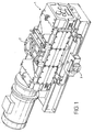
- Figure 1 is a perspective view of a mechanical pump according to the present invention; and
- Figure 2 is an exploded detail of the mechanical pump of Figure 1 illustrating a flame arrester incorporated within the pump.
-
- As shown, a
mechanical pump 1 includes aninlet 2 and anoutlet 3 spaced from theinlet 2 for the passage therethrough of a fluid to be pumped. - Immediately adjacent the
inlet 2 there is located aflame arrester 4 which includes aflame arresting element 6 made, for example, from mesh material, removably mounted within ahousing 8. Thehousing 8 has a rectangularbox section body 10 opposite ends of which are closed by removable cover plates 12 (only one shown). Since thebody 10 andcover plates 12 form part of thepump 1 and attain high temperatures when thepump 10 is running they can be made from relatively cheap material such as grey or spheriodal graphite iron without the risk of corrosion. - In use, with one or both
cover plates 12 removed, theflame arresting element 6 is slid in place within thebody 10 of thehousing 8. The or eachcover place 12 is then bolted to its respective end face of thebody 10 to seal the flame arresting element within thehousing 8. - Finally, the
flame arresting element 6 is clamped in place by for example a plurality ofbolts 14 or other mechanical means in thehousing 8. Thebolts 14 are sealed within the housing to make them leak-tight. - The
flame arrester 4 is bolted to the pump casing between the casing and thepump inlet 2 and is thereby incorporated within the body of thepump 1. - It will be apparent that the
flame arresting element 6 can be removed from thepump 1 for cleaning or replacement by removing one of thecover plates 12, releasing thebolts 14, and sliding theflame arresting element 6 out from thebody 10 of thehousing 8. - In this manner, the
flame arresting element 6 can be removed without disturbing any process pipework to which thepump 1 is attached. - It will be evident that a second flame arrester can be incorporated within the
pump 1 immediately adjacent theoutlet 3 of the pump in a similar manner to that described with respect toflame arrester 4 and thepump inlet 2. - Although the
housing 8 is described and shown having a rectangularbox section body 10, other shapes could be used, for example oval or circular.
Claims (8)
- A mechanical pump having an inlet and spaced therefrom an outlet for the passage of fluid therethrough and incorporating at least one flame arrester.
- A mechanical pump as claimed in Claim 1 in which said at least one flame arrester is located immediately adjacent the pump inlet.
- A mechanical pump as claimed in Claim 1 in which two flame arresters are incorporated in the pump, one being located immediately adjacent the pump inlet and the second being located immediately adjacent the pump outlet.
- A mechanical pump as claimed in Claim 1, Claim 2 or Claim 3 in which the or each flame arrester includes a flame arresting element removably mounted within a housing.
- A mechanical pump as claimed in Claim 4 in which the flame arresting element is made from a mesh material.
- A mechanical pump as claimed in Claim 4 or Claim 5 in which the housing has a rectangular box section body opposite ends of which are closed by removable cover plates.
- A mechanical pump as claimed in Claim 6 in which the housing is made from spheriodal graphite iron.
- A mechanical pump constructed, arranged and adopted to operate substantially as hereinbefore described with reference to and as illustrated in the Figures of the accompanying drawings.
Applications Claiming Priority (2)
| Application Number | Priority Date | Filing Date | Title |
|---|---|---|---|
| GB0123873 | 2001-10-04 | ||
| GBGB0123873.2A GB0123873D0 (en) | 2001-10-04 | 2001-10-04 | Mechanical pumps |
Publications (3)
| Publication Number | Publication Date |
|---|---|
| EP1300591A2 true EP1300591A2 (en) | 2003-04-09 |
| EP1300591A3 EP1300591A3 (en) | 2009-09-16 |
| EP1300591B1 EP1300591B1 (en) | 2013-09-04 |
Family
ID=9923254
Family Applications (1)
| Application Number | Title | Priority Date | Filing Date |
|---|---|---|---|
| EP02256526.1A Expired - Lifetime EP1300591B1 (en) | 2001-10-04 | 2002-09-20 | Mechanical pump with integrated flame arrester |
Country Status (6)
| Country | Link |
|---|---|
| US (1) | US6942466B2 (en) |
| EP (1) | EP1300591B1 (en) |
| JP (1) | JP2003176789A (en) |
| KR (1) | KR20030029021A (en) |
| CN (1) | CN1281867C (en) |
| GB (1) | GB0123873D0 (en) |
Families Citing this family (2)
| Publication number | Priority date | Publication date | Assignee | Title |
|---|---|---|---|---|
| FR3046081B1 (en) * | 2015-12-23 | 2022-03-18 | Soc De Tolerie Industrielle Francaise Stif | FLAME ARRESTER DEVICE AND ASSOCIATED DEPRESSURIZATION DEVICE, AND METHOD OF INSTALLING THEM |
| DE102019128602B3 (en) * | 2019-10-23 | 2021-02-11 | Leistritz Pumpen Gmbh | Screw pump |
Citations (3)
| Publication number | Priority date | Publication date | Assignee | Title |
|---|---|---|---|---|
| US3658444A (en) | 1970-05-20 | 1972-04-25 | Holley Carburetor Co | Holley fuel pump |
| US5007806A (en) | 1989-03-30 | 1991-04-16 | Mallory, Inc. | Fuel pump |
| US5591019A (en) | 1996-02-28 | 1997-01-07 | Delaware Capital Formation, Inc. | Vapor recovery pump |
Family Cites Families (22)
| Publication number | Priority date | Publication date | Assignee | Title |
|---|---|---|---|---|
| GB565271A (en) | 1942-09-29 | 1944-11-03 | Pulsometer Eng Co | Improvements in or relating to pumps |
| GB562907A (en) | 1943-02-10 | 1944-07-20 | Thompson Prod Inc | Improvements in or relating to fuel-pumping systems |
| GB834689A (en) | 1957-06-03 | 1960-05-11 | Lucas Industries Ltd | Rotary fuel pumps |
| US3135211A (en) * | 1960-09-28 | 1964-06-02 | Integral Motor Pump Corp | Motor and pump assembly |
| NL126726C (en) * | 1962-06-28 | 1969-09-15 | ||
| US3338223A (en) * | 1966-05-26 | 1967-08-29 | Robert E Williams | Carburetors |
| US3535066A (en) * | 1968-08-26 | 1970-10-20 | Wagner Mining Scoop Inc | Flame arrester |
| US4268289A (en) * | 1979-04-11 | 1981-05-19 | Barbron Corporation | Flame arresting air filter element |
| DE3312828A1 (en) * | 1983-04-09 | 1984-10-11 | Flutec Fluidtechnische Geräte GmbH, 6603 Sulzbach | DEVICE FOR CONVEYING A PRESSURE, IN PARTICULAR OIL |
| JPS61175262A (en) * | 1985-01-29 | 1986-08-06 | Mitsubishi Electric Corp | Fuel feeding pump |
| US4975098A (en) * | 1988-05-31 | 1990-12-04 | Lee John H S | Low pressure drop detonation arrestor for pipelines |
| US5156536A (en) * | 1990-09-26 | 1992-10-20 | Wilson Robert G | Safety hand pump |
| DE4141434C2 (en) | 1991-12-16 | 1993-11-25 | Fafnir Gmbh | Diaphragm vacuum pump |
| US5344313A (en) * | 1993-04-30 | 1994-09-06 | Chevron Research And Technology Company | Fugitive volatile organic compound vapor collection system |
| JPH07293468A (en) * | 1994-04-28 | 1995-11-07 | Toshiba Corp | Closed type compressor |
| JP3687011B2 (en) * | 1995-10-31 | 2005-08-24 | 社団法人寒地港湾技術研究センター | Seal structure of oscillating vane pump |
| US5752812A (en) | 1996-02-28 | 1998-05-19 | Delaware Capital Formation, Inc. | Vapor recovery pump |
| KR100232841B1 (en) * | 1997-10-04 | 1999-12-01 | 윤승찬 | Gas regulator having interior type flashback arrestor |
| JP3831108B2 (en) * | 1998-03-23 | 2006-10-11 | 大晃機械工業株式会社 | Dry vacuum pump |
| JP4049928B2 (en) * | 1999-02-10 | 2008-02-20 | 株式会社東芝 | Hydrogen ventilator |
| GB9906439D0 (en) * | 1999-03-19 | 1999-05-12 | Boc Group Plc | Improvements in flame arresters |
| KR200236963Y1 (en) * | 2001-03-20 | 2001-10-08 | 주식회사 앤투앤 | A vacuum filter |
-
2001
- 2001-10-04 GB GBGB0123873.2A patent/GB0123873D0/en not_active Ceased
-
2002
- 2002-09-20 EP EP02256526.1A patent/EP1300591B1/en not_active Expired - Lifetime
- 2002-09-27 JP JP2002282802A patent/JP2003176789A/en active Pending
- 2002-10-02 US US10/262,688 patent/US6942466B2/en not_active Expired - Lifetime
- 2002-10-02 KR KR1020020060047A patent/KR20030029021A/en active Search and Examination
- 2002-10-04 CN CNB021529442A patent/CN1281867C/en not_active Expired - Lifetime
Patent Citations (3)
| Publication number | Priority date | Publication date | Assignee | Title |
|---|---|---|---|---|
| US3658444A (en) | 1970-05-20 | 1972-04-25 | Holley Carburetor Co | Holley fuel pump |
| US5007806A (en) | 1989-03-30 | 1991-04-16 | Mallory, Inc. | Fuel pump |
| US5591019A (en) | 1996-02-28 | 1997-01-07 | Delaware Capital Formation, Inc. | Vapor recovery pump |
Also Published As
| Publication number | Publication date |
|---|---|
| US6942466B2 (en) | 2005-09-13 |
| GB0123873D0 (en) | 2001-11-28 |
| EP1300591B1 (en) | 2013-09-04 |
| KR20030029021A (en) | 2003-04-11 |
| EP1300591A3 (en) | 2009-09-16 |
| CN1281867C (en) | 2006-10-25 |
| CN1412442A (en) | 2003-04-23 |
| JP2003176789A (en) | 2003-06-27 |
| US20030086795A1 (en) | 2003-05-08 |
Similar Documents
| Publication | Publication Date | Title |
|---|---|---|
| JP4276177B2 (en) | Compressor unit | |
| US9841027B2 (en) | Pump pressure relief system | |
| EP1300591A2 (en) | Mechanical pump with integrated flame arrester | |
| ATE551124T1 (en) | DRIVE UNIT, ESPECIALLY FOR USE IN CONNECTION WITH TANK CLEANING DEVICES | |
| WO2016090032A1 (en) | High-capacity fluid pump | |
| KR101342896B1 (en) | Water filter for water lubricated air compressor | |
| JPH0798088A (en) | Throttling device, particularly choke valve | |
| AU2003233324A1 (en) | Device for filtering fluids that are conveyed under a high pressure | |
| KR950700492A (en) | Separator Vessel | |
| US1488671A (en) | Strainer | |
| CN210661871U (en) | High-safety protection device | |
| CN216306942U (en) | Pipeline protection device and municipal groove structure | |
| CN205664040U (en) | Fire pump connects | |
| CN212067980U (en) | Pipeline filter with conveniently replaced filter element | |
| CN110594128A (en) | Vacuum pump | |
| RU3976U1 (en) | RESPIRATORY VALVE | |
| RU2269052C2 (en) | Check valve | |
| US4276162A (en) | Flame resistant sump assembly | |
| CN214196706U (en) | Multistage sand-resistant submersible electric pump | |
| CN210874401U (en) | Novel lubricating oil purifying device | |
| Golwalkar et al. | Piping Design and Pumping Systems | |
| CN108150447A (en) | A kind of novel freezing water pump of low abrasion for refrigeration equipment | |
| EP0708283A2 (en) | Ball check valve | |
| US2733043A (en) | M smith | |
| Verhulsdonk | Pulsation free rotary piston pumps: a case of application in a sewage treatment plant |
Legal Events
| Date | Code | Title | Description |
|---|---|---|---|
| PUAI | Public reference made under article 153(3) epc to a published international application that has entered the european phase |
Free format text: ORIGINAL CODE: 0009012 |
|
| AK | Designated contracting states |
Kind code of ref document: A2 Designated state(s): AT BE BG CH CY CZ DE DK EE ES FI FR GB GR IE IT LI LU MC NL PT SE SK TR Designated state(s): AT BE BG CH CY CZ DE DK EE ES FI FR GB GR IE IT LI LU MC NL PT SE SK TR |
|
| AX | Request for extension of the european patent |
Extension state: AL LT LV MK RO SI |
|
| RAP1 | Party data changed (applicant data changed or rights of an application transferred) |
Owner name: EDWARDS LIMITED |
|
| PUAL | Search report despatched |
Free format text: ORIGINAL CODE: 0009013 |
|
| AK | Designated contracting states |
Kind code of ref document: A3 Designated state(s): AT BE BG CH CY CZ DE DK EE ES FI FR GB GR IE IT LI LU MC NL PT SE SK TR |
|
| AX | Request for extension of the european patent |
Extension state: AL LT LV MK RO SI |
|
| 17P | Request for examination filed |
Effective date: 20090825 |
|
| 17Q | First examination report despatched |
Effective date: 20090928 |
|
| AKX | Designation fees paid |
Designated state(s): AT BE BG CH CY CZ DE DK EE ES FI FR GB GR IE IT LI LU MC NL PT SE SK TR |
|
| GRAP | Despatch of communication of intention to grant a patent |
Free format text: ORIGINAL CODE: EPIDOSNIGR1 |
|
| RIC1 | Information provided on ipc code assigned before grant |
Ipc: F04C 28/28 20060101ALI20121123BHEP Ipc: A62C 4/00 20060101ALI20121123BHEP Ipc: F04B 53/00 20060101AFI20121123BHEP Ipc: F04D 29/42 20060101ALI20121123BHEP |
|
| GRAS | Grant fee paid |
Free format text: ORIGINAL CODE: EPIDOSNIGR3 |
|
| GRAA | (expected) grant |
Free format text: ORIGINAL CODE: 0009210 |
|
| AK | Designated contracting states |
Kind code of ref document: B1 Designated state(s): AT BE BG CH CY CZ DE DK EE ES FI FR GB GR IE IT LI LU MC NL PT SE SK TR |
|
| REG | Reference to a national code |
Ref country code: GB Ref legal event code: FG4D |
|
| REG | Reference to a national code |
Ref country code: DE Ref legal event code: R081 Ref document number: 60245465 Country of ref document: DE Owner name: EDWARDS LTD., BURGESS HILL, GB Free format text: FORMER OWNER: THE BOC GROUP PLC, WINDLESHAM, SURREY, GB |
|
| REG | Reference to a national code |
Ref country code: CH Ref legal event code: EP |
|
| REG | Reference to a national code |
Ref country code: AT Ref legal event code: REF Ref document number: 630696 Country of ref document: AT Kind code of ref document: T Effective date: 20130915 |
|
| REG | Reference to a national code |
Ref country code: IE Ref legal event code: FG4D |
|
| REG | Reference to a national code |
Ref country code: DE Ref legal event code: R096 Ref document number: 60245465 Country of ref document: DE Effective date: 20131031 |
|
| REG | Reference to a national code |
Ref country code: AT Ref legal event code: MK05 Ref document number: 630696 Country of ref document: AT Kind code of ref document: T Effective date: 20130904 |
|
| REG | Reference to a national code |
Ref country code: NL Ref legal event code: VDEP Effective date: 20130904 |
|
| PG25 | Lapsed in a contracting state [announced via postgrant information from national office to epo] |
Ref country code: CY Free format text: LAPSE BECAUSE OF NON-PAYMENT OF DUE FEES Effective date: 20130530 Ref country code: AT Free format text: LAPSE BECAUSE OF FAILURE TO SUBMIT A TRANSLATION OF THE DESCRIPTION OR TO PAY THE FEE WITHIN THE PRESCRIBED TIME-LIMIT Effective date: 20130904 Ref country code: SE Free format text: LAPSE BECAUSE OF FAILURE TO SUBMIT A TRANSLATION OF THE DESCRIPTION OR TO PAY THE FEE WITHIN THE PRESCRIBED TIME-LIMIT Effective date: 20130904 |
|
| REG | Reference to a national code |
Ref country code: NL Ref legal event code: VDEP Effective date: 20130904 |
|
| PG25 | Lapsed in a contracting state [announced via postgrant information from national office to epo] |
Ref country code: ES Free format text: LAPSE BECAUSE OF FAILURE TO SUBMIT A TRANSLATION OF THE DESCRIPTION OR TO PAY THE FEE WITHIN THE PRESCRIBED TIME-LIMIT Effective date: 20130904 Ref country code: FI Free format text: LAPSE BECAUSE OF FAILURE TO SUBMIT A TRANSLATION OF THE DESCRIPTION OR TO PAY THE FEE WITHIN THE PRESCRIBED TIME-LIMIT Effective date: 20130904 Ref country code: GR Free format text: LAPSE BECAUSE OF FAILURE TO SUBMIT A TRANSLATION OF THE DESCRIPTION OR TO PAY THE FEE WITHIN THE PRESCRIBED TIME-LIMIT Effective date: 20131205 |
|
| PG25 | Lapsed in a contracting state [announced via postgrant information from national office to epo] |
Ref country code: BE Free format text: LAPSE BECAUSE OF FAILURE TO SUBMIT A TRANSLATION OF THE DESCRIPTION OR TO PAY THE FEE WITHIN THE PRESCRIBED TIME-LIMIT Effective date: 20130904 Ref country code: CY Free format text: LAPSE BECAUSE OF NON-PAYMENT OF DUE FEES Effective date: 20130904 |
|
| PG25 | Lapsed in a contracting state [announced via postgrant information from national office to epo] |
Ref country code: NL Free format text: LAPSE BECAUSE OF FAILURE TO SUBMIT A TRANSLATION OF THE DESCRIPTION OR TO PAY THE FEE WITHIN THE PRESCRIBED TIME-LIMIT Effective date: 20130904 Ref country code: CZ Free format text: LAPSE BECAUSE OF FAILURE TO SUBMIT A TRANSLATION OF THE DESCRIPTION OR TO PAY THE FEE WITHIN THE PRESCRIBED TIME-LIMIT Effective date: 20130904 Ref country code: EE Free format text: LAPSE BECAUSE OF FAILURE TO SUBMIT A TRANSLATION OF THE DESCRIPTION OR TO PAY THE FEE WITHIN THE PRESCRIBED TIME-LIMIT Effective date: 20130904 Ref country code: SK Free format text: LAPSE BECAUSE OF FAILURE TO SUBMIT A TRANSLATION OF THE DESCRIPTION OR TO PAY THE FEE WITHIN THE PRESCRIBED TIME-LIMIT Effective date: 20130904 |
|
| REG | Reference to a national code |
Ref country code: CH Ref legal event code: PL |
|
| REG | Reference to a national code |
Ref country code: DE Ref legal event code: R097 Ref document number: 60245465 Country of ref document: DE |
|
| PG25 | Lapsed in a contracting state [announced via postgrant information from national office to epo] |
Ref country code: PT Free format text: LAPSE BECAUSE OF FAILURE TO SUBMIT A TRANSLATION OF THE DESCRIPTION OR TO PAY THE FEE WITHIN THE PRESCRIBED TIME-LIMIT Effective date: 20140106 Ref country code: MC Free format text: LAPSE BECAUSE OF FAILURE TO SUBMIT A TRANSLATION OF THE DESCRIPTION OR TO PAY THE FEE WITHIN THE PRESCRIBED TIME-LIMIT Effective date: 20130904 |
|
| REG | Reference to a national code |
Ref country code: IE Ref legal event code: MM4A |
|
| PLBE | No opposition filed within time limit |
Free format text: ORIGINAL CODE: 0009261 |
|
| STAA | Information on the status of an ep patent application or granted ep patent |
Free format text: STATUS: NO OPPOSITION FILED WITHIN TIME LIMIT |
|
| PG25 | Lapsed in a contracting state [announced via postgrant information from national office to epo] |
Ref country code: LI Free format text: LAPSE BECAUSE OF NON-PAYMENT OF DUE FEES Effective date: 20130930 Ref country code: IE Free format text: LAPSE BECAUSE OF NON-PAYMENT OF DUE FEES Effective date: 20130920 Ref country code: CH Free format text: LAPSE BECAUSE OF NON-PAYMENT OF DUE FEES Effective date: 20130930 |
|
| 26N | No opposition filed |
Effective date: 20140605 |
|
| GBPC | Gb: european patent ceased through non-payment of renewal fee |
Effective date: 20131204 |
|
| REG | Reference to a national code |
Ref country code: DE Ref legal event code: R097 Ref document number: 60245465 Country of ref document: DE Effective date: 20140605 |
|
| PG25 | Lapsed in a contracting state [announced via postgrant information from national office to epo] |
Ref country code: DK Free format text: LAPSE BECAUSE OF FAILURE TO SUBMIT A TRANSLATION OF THE DESCRIPTION OR TO PAY THE FEE WITHIN THE PRESCRIBED TIME-LIMIT Effective date: 20130904 |
|
| PG25 | Lapsed in a contracting state [announced via postgrant information from national office to epo] |
Ref country code: GB Free format text: LAPSE BECAUSE OF NON-PAYMENT OF DUE FEES Effective date: 20131204 |
|
| PG25 | Lapsed in a contracting state [announced via postgrant information from national office to epo] |
Ref country code: TR Free format text: LAPSE BECAUSE OF FAILURE TO SUBMIT A TRANSLATION OF THE DESCRIPTION OR TO PAY THE FEE WITHIN THE PRESCRIBED TIME-LIMIT Effective date: 20130904 |
|
| PG25 | Lapsed in a contracting state [announced via postgrant information from national office to epo] |
Ref country code: LU Free format text: LAPSE BECAUSE OF NON-PAYMENT OF DUE FEES Effective date: 20130920 Ref country code: BG Free format text: LAPSE BECAUSE OF FAILURE TO SUBMIT A TRANSLATION OF THE DESCRIPTION OR TO PAY THE FEE WITHIN THE PRESCRIBED TIME-LIMIT Effective date: 20130904 |
|
| REG | Reference to a national code |
Ref country code: FR Ref legal event code: PLFP Year of fee payment: 15 |
|
| REG | Reference to a national code |
Ref country code: FR Ref legal event code: PLFP Year of fee payment: 16 |
|
| REG | Reference to a national code |
Ref country code: DE Ref legal event code: R082 Ref document number: 60245465 Country of ref document: DE Representative=s name: FLEUCHAUS & GALLO PARTNERSCHAFT MBB PATENTANWA, DE Ref country code: DE Ref legal event code: R082 Ref document number: 60245465 Country of ref document: DE Representative=s name: FLEUCHAUS & GALLO PARTNERSCHAFT MBB, DE Ref country code: DE Ref legal event code: R081 Ref document number: 60245465 Country of ref document: DE Owner name: EDWARDS LTD., BURGESS HILL, GB Free format text: FORMER OWNER: EDWARDS LTD., CRAWLEY, WEST SUSSEX, GB |
|
| REG | Reference to a national code |
Ref country code: FR Ref legal event code: PLFP Year of fee payment: 17 |
|
| REG | Reference to a national code |
Ref country code: FR Ref legal event code: CA Effective date: 20180906 |
|
| PGFP | Annual fee paid to national office [announced via postgrant information from national office to epo] |
Ref country code: IT Payment date: 20210922 Year of fee payment: 20 Ref country code: FR Payment date: 20210927 Year of fee payment: 20 |
|
| PGFP | Annual fee paid to national office [announced via postgrant information from national office to epo] |
Ref country code: DE Payment date: 20210929 Year of fee payment: 20 |
|
| REG | Reference to a national code |
Ref country code: DE Ref legal event code: R071 Ref document number: 60245465 Country of ref document: DE |