EP1291521A1 - Wind turbine nacelle with moving crane - Google Patents
Wind turbine nacelle with moving crane Download PDFInfo
- Publication number
- EP1291521A1 EP1291521A1 EP01203373A EP01203373A EP1291521A1 EP 1291521 A1 EP1291521 A1 EP 1291521A1 EP 01203373 A EP01203373 A EP 01203373A EP 01203373 A EP01203373 A EP 01203373A EP 1291521 A1 EP1291521 A1 EP 1291521A1
- Authority
- EP
- European Patent Office
- Prior art keywords
- nacelle
- wind turbine
- hub
- rotor
- attached
- Prior art date
- Legal status (The legal status is an assumption and is not a legal conclusion. Google has not performed a legal analysis and makes no representation as to the accuracy of the status listed.)
- Withdrawn
Links
- 238000012423 maintenance Methods 0.000 description 11
- 238000010276 construction Methods 0.000 description 3
- 230000007797 corrosion Effects 0.000 description 2
- 238000005260 corrosion Methods 0.000 description 2
- 230000008030 elimination Effects 0.000 description 2
- 238000003379 elimination reaction Methods 0.000 description 2
- 230000002349 favourable effect Effects 0.000 description 1
Images


Classifications
-
- F—MECHANICAL ENGINEERING; LIGHTING; HEATING; WEAPONS; BLASTING
- F03—MACHINES OR ENGINES FOR LIQUIDS; WIND, SPRING, OR WEIGHT MOTORS; PRODUCING MECHANICAL POWER OR A REACTIVE PROPULSIVE THRUST, NOT OTHERWISE PROVIDED FOR
- F03D—WIND MOTORS
- F03D7/00—Controlling wind motors
- F03D7/02—Controlling wind motors the wind motors having rotation axis substantially parallel to the air flow entering the rotor
- F03D7/0264—Controlling wind motors the wind motors having rotation axis substantially parallel to the air flow entering the rotor for stopping; controlling in emergency situations
- F03D7/0268—Parking or storm protection
-
- F—MECHANICAL ENGINEERING; LIGHTING; HEATING; WEAPONS; BLASTING
- F03—MACHINES OR ENGINES FOR LIQUIDS; WIND, SPRING, OR WEIGHT MOTORS; PRODUCING MECHANICAL POWER OR A REACTIVE PROPULSIVE THRUST, NOT OTHERWISE PROVIDED FOR
- F03D—WIND MOTORS
- F03D13/00—Assembly, mounting or commissioning of wind motors; Arrangements specially adapted for transporting wind motor components
- F03D13/10—Assembly of wind motors; Arrangements for erecting wind motors
-
- F—MECHANICAL ENGINEERING; LIGHTING; HEATING; WEAPONS; BLASTING
- F03—MACHINES OR ENGINES FOR LIQUIDS; WIND, SPRING, OR WEIGHT MOTORS; PRODUCING MECHANICAL POWER OR A REACTIVE PROPULSIVE THRUST, NOT OTHERWISE PROVIDED FOR
- F03D—WIND MOTORS
- F03D13/00—Assembly, mounting or commissioning of wind motors; Arrangements specially adapted for transporting wind motor components
- F03D13/20—Arrangements for mounting or supporting wind motors; Masts or towers for wind motors
-
- F—MECHANICAL ENGINEERING; LIGHTING; HEATING; WEAPONS; BLASTING
- F03—MACHINES OR ENGINES FOR LIQUIDS; WIND, SPRING, OR WEIGHT MOTORS; PRODUCING MECHANICAL POWER OR A REACTIVE PROPULSIVE THRUST, NOT OTHERWISE PROVIDED FOR
- F03D—WIND MOTORS
- F03D80/00—Details, components or accessories not provided for in groups F03D1/00 - F03D17/00
- F03D80/80—Arrangement of components within nacelles or towers
- F03D80/88—Arrangement of components within nacelles or towers of mechanical components
-
- F—MECHANICAL ENGINEERING; LIGHTING; HEATING; WEAPONS; BLASTING
- F05—INDEXING SCHEMES RELATING TO ENGINES OR PUMPS IN VARIOUS SUBCLASSES OF CLASSES F01-F04
- F05B—INDEXING SCHEME RELATING TO WIND, SPRING, WEIGHT, INERTIA OR LIKE MOTORS, TO MACHINES OR ENGINES FOR LIQUIDS COVERED BY SUBCLASSES F03B, F03D AND F03G
- F05B2230/00—Manufacture
- F05B2230/60—Assembly methods
-
- F—MECHANICAL ENGINEERING; LIGHTING; HEATING; WEAPONS; BLASTING
- F05—INDEXING SCHEMES RELATING TO ENGINES OR PUMPS IN VARIOUS SUBCLASSES OF CLASSES F01-F04
- F05B—INDEXING SCHEME RELATING TO WIND, SPRING, WEIGHT, INERTIA OR LIKE MOTORS, TO MACHINES OR ENGINES FOR LIQUIDS COVERED BY SUBCLASSES F03B, F03D AND F03G
- F05B2230/00—Manufacture
- F05B2230/80—Repairing, retrofitting or upgrading methods
-
- F—MECHANICAL ENGINEERING; LIGHTING; HEATING; WEAPONS; BLASTING
- F05—INDEXING SCHEMES RELATING TO ENGINES OR PUMPS IN VARIOUS SUBCLASSES OF CLASSES F01-F04
- F05B—INDEXING SCHEME RELATING TO WIND, SPRING, WEIGHT, INERTIA OR LIKE MOTORS, TO MACHINES OR ENGINES FOR LIQUIDS COVERED BY SUBCLASSES F03B, F03D AND F03G
- F05B2240/00—Components
- F05B2240/10—Stators
- F05B2240/14—Casings, housings, nacelles, gondels or the like, protecting or supporting assemblies there within
-
- F—MECHANICAL ENGINEERING; LIGHTING; HEATING; WEAPONS; BLASTING
- F05—INDEXING SCHEMES RELATING TO ENGINES OR PUMPS IN VARIOUS SUBCLASSES OF CLASSES F01-F04
- F05B—INDEXING SCHEME RELATING TO WIND, SPRING, WEIGHT, INERTIA OR LIKE MOTORS, TO MACHINES OR ENGINES FOR LIQUIDS COVERED BY SUBCLASSES F03B, F03D AND F03G
- F05B2240/00—Components
- F05B2240/90—Mounting on supporting structures or systems
- F05B2240/91—Mounting on supporting structures or systems on a stationary structure
- F05B2240/916—Mounting on supporting structures or systems on a stationary structure with provision for hoisting onto the structure
-
- F—MECHANICAL ENGINEERING; LIGHTING; HEATING; WEAPONS; BLASTING
- F05—INDEXING SCHEMES RELATING TO ENGINES OR PUMPS IN VARIOUS SUBCLASSES OF CLASSES F01-F04
- F05B—INDEXING SCHEME RELATING TO WIND, SPRING, WEIGHT, INERTIA OR LIKE MOTORS, TO MACHINES OR ENGINES FOR LIQUIDS COVERED BY SUBCLASSES F03B, F03D AND F03G
- F05B2260/00—Function
- F05B2260/30—Retaining components in desired mutual position
- F05B2260/31—Locking rotor in position
-
- Y—GENERAL TAGGING OF NEW TECHNOLOGICAL DEVELOPMENTS; GENERAL TAGGING OF CROSS-SECTIONAL TECHNOLOGIES SPANNING OVER SEVERAL SECTIONS OF THE IPC; TECHNICAL SUBJECTS COVERED BY FORMER USPC CROSS-REFERENCE ART COLLECTIONS [XRACs] AND DIGESTS
- Y02—TECHNOLOGIES OR APPLICATIONS FOR MITIGATION OR ADAPTATION AGAINST CLIMATE CHANGE
- Y02E—REDUCTION OF GREENHOUSE GAS [GHG] EMISSIONS, RELATED TO ENERGY GENERATION, TRANSMISSION OR DISTRIBUTION
- Y02E10/00—Energy generation through renewable energy sources
- Y02E10/70—Wind energy
- Y02E10/72—Wind turbines with rotation axis in wind direction
-
- Y—GENERAL TAGGING OF NEW TECHNOLOGICAL DEVELOPMENTS; GENERAL TAGGING OF CROSS-SECTIONAL TECHNOLOGIES SPANNING OVER SEVERAL SECTIONS OF THE IPC; TECHNICAL SUBJECTS COVERED BY FORMER USPC CROSS-REFERENCE ART COLLECTIONS [XRACs] AND DIGESTS
- Y02—TECHNOLOGIES OR APPLICATIONS FOR MITIGATION OR ADAPTATION AGAINST CLIMATE CHANGE
- Y02E—REDUCTION OF GREENHOUSE GAS [GHG] EMISSIONS, RELATED TO ENERGY GENERATION, TRANSMISSION OR DISTRIBUTION
- Y02E10/00—Energy generation through renewable energy sources
- Y02E10/70—Wind energy
- Y02E10/728—Onshore wind turbines
-
- Y—GENERAL TAGGING OF NEW TECHNOLOGICAL DEVELOPMENTS; GENERAL TAGGING OF CROSS-SECTIONAL TECHNOLOGIES SPANNING OVER SEVERAL SECTIONS OF THE IPC; TECHNICAL SUBJECTS COVERED BY FORMER USPC CROSS-REFERENCE ART COLLECTIONS [XRACs] AND DIGESTS
- Y02—TECHNOLOGIES OR APPLICATIONS FOR MITIGATION OR ADAPTATION AGAINST CLIMATE CHANGE
- Y02P—CLIMATE CHANGE MITIGATION TECHNOLOGIES IN THE PRODUCTION OR PROCESSING OF GOODS
- Y02P70/00—Climate change mitigation technologies in the production process for final industrial or consumer products
- Y02P70/50—Manufacturing or production processes characterised by the final manufactured product
Definitions
- the invention relates to a wind turbine having a nacelle housing a main shaft, a gear box and a generator, the nacelle being positioned on a tower, and to the nacelle a hub with rotor blades being attached.
- the main shaft, the gear box and the generator in a nacelle positioned on a post.
- the typical height of the tower is 40-60 meters or more.
- a wind turbine in accordance with one aspect of the invention is characterised in that it comprises a rotor disk in between the hub and the nacelle attached to the hub and co-rotating in operation with the hub, and the nacelle comprises a rotor disk lock device for locking the rotor disk and fixation means for fixating the rotor disk to the nacelle.
- the locking meaning preventing of rotation
- fixation of the rotor disk makes it possible to exchange the gear box, main shaft and main bearing without having to bring down the blades of the rotor hub, as is customary. This reduces the costs of maintenance considerably, which is of great importance. It also makes an overhaul of the machinery inside the nacelle simpler, which can be used to extend the service life-time of the structure itself.
- the rotor disk is provided with tapered apertures and the nacelle is provided with a movable shaft with a tapered end to co-operate with the tapered apertures of the rotor disk to lock the rotor disk.
- the tapered shaft and apertures allow for compensation of misalignment between the shaft and the holes and the elimination or at least reduction of play between the shaft and the holes. This increase the speed and accuracy with which the rotor is locked reducing the time needed for a maintenance or repair and reducing wear on the rotor locking device.
- the shaft is movable from inside the nacelle.
- the rotor lock disk comprises 4n, where n is the number of blades, tapered holes substantially equally distributed. The rotor can therewith be locked in discrete positions allowing each of the blades to be locked in a vertical upward, vertical downward and horizontal position.
- the rotor disk may form an integral part of the hub, but is preferably a separate part attached to the hub. This enables the hub to be taken off from the nacelle, while the locked and fixed rotor disk stays in place.
- the rotor disk preferably has a generally bowl or curved shaped form, the smaller section facing the hub, the larger section facing the nacelle.
- the infrastructural costs can rise to 70% of the total costs.
- the service life of the wind turbine is preferably increased and the down time during maintenance and repair reduced.
- a wind turbine in accordance with another aspect of the invention is characterised in that the nacelle comprises an overhead frame from which the generator is suspended and doors at the bottom of the nacelle.
- This construction allows the turbine parts housed by the nacelle to be hoisted and lowered by a ground based winch, using the overhead frame as a bridge to which pulleys are attached.
- Use of expensive floating cranes can therewith be avoided or in any case reduced, which reduces the costs of maintenance and the time needed for such maintenance and dependence on weather conditions is also reduced.
- the nacelle comprises a mobile beam section attachable to the overhead frame which, in attached position, extends over the hub.
- This construction allows the hub and the blades to be hoisted and lowered by a ground based winch, using the mobile beam section and the overhead frame as bridges to which pulleys are attached.
- the advantages are the same as given above.
- the nacelle comprises a skeleton structure comprising a tube shaped part, the longitudinal axis of which is in parallel with the rotation axis of the wind turbine, a front part facing the hub being an integral cylindrical body, a rear part facing away from the hub being cut at an oblique angle, the overhead frame being attached to an outside of the front part, while being attached to or near a rear-most section of the rear part via buttresses.
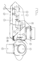
- Figure 1 shows in partial cross-sectional view a wind turbine.
- the turbine comprises on a tower 1 a structure 2, which houses means to convert the rotational energy of the blades 4 into electrical energy or energy of another form.
- the blades are connected to a hub 3.
- the means to convert the rotational energy of the blades into electrical energy comprise a main shaft (11), a gear box 10 and a generator 9, as is shown in more detail in Figure 2.
- the nacelle is provided with rotor locking means comprising means 5a in the nacelle and a rotor disk 5b positioned between the hub 3 and the nacelle 2.
- the nacelle comprises a beam 6 to which the generator is hung by means of attachment means 8.
- a wind turbine in accordance with the invention comprises a rotor lock device 5a and a rotor disk 5b.
- the rotor disk lock device locks the rotor disk, i.e. prevents rotation of the rotor disk and thereby the with the rotor coupled hub and blades.
- Fixation of the rotor disk 5b is done by means of fixation means 12.
- the fixation of the rotor disk, hub and blades makes it possible to exchange the gear box, main shaft and main bearing without having to bring down the blades of the rotor hub, as is customary. This reduces the costs of maintenance considerably, which is of great importance.
- the rotor lock device preferably (see figure 3) comprises tapered apertures 43 and the nacelle is provided with a movable shaft 41 with a tapered end to co-operate with the tapered apertures 43 of the rotor disk to lock the rotor disk.
- the tapered shaft and apertures allow for compensation of misalignment between the shaft and the holes and the elimination or reduction of play between of the shaft and the holes.
- the nacelle has moving means inside the nacelle for moving the shaft. Placing this means inside the nacelle enables operators to safely lock and unlock the rotor.
- the moving means comprise a manually operatable turn wheel 42 which is also used for retracting the shaft for unlocking the rotor.
- the rotor disk fixing device comprise a number (e.g. 12) screws plugs 52 in front part 51 of the nacelle (see Fig. 4).
- the rotor can be fixed against the nacelle front part 51 by fastening these screw plugs against the rotor lock disk 5b, using a spanner wrench. After fastening the screw plugs, studs 53 and nuts 54 can be mounted to make a firm connection.
- the rotor lock disk 5b comprises 4n, where n is the number of blades, in this example with three blades 12 tapered holes substantially equally distributed.
- the rotor disk can therewith be locked in 12 discrete positions. These positions allow each of the blades to be locked in a vertical upward, vertical downward and horizontal position.
- the rotor disk is preferably as shown in figure 6 of a bowl or curved shaped, having a large diameter part being attached to the nacelle and a smaller diameter part being attached to the hub, at different planes.
- the infrastructural costs can rise to 70% of the total costs.
- the service life of the wind turbine is preferably increased and the down time during maintenance and repair reduced.
- FIGS 6 to 11 illustrate the wind turbine in accordance with the other aspect of the invention, more in particular illustrating hoisting and lowering of several components of the wind turbine, either components housed inside the turbine (figures 6 to 8) or outside (figures 9 and 110).
- the nacelle comprises an overhead frame 6 and doors 7 at the bottom of the nacelle. Opening the doors (schematically indicated in the figures) allows the generator 9 to be hoisted and lifted by means of a ground-based winch (not shown in the figures) via pulleys 70 on the overhead frame. Schematically the lines from and to the winch and the to be hoisted or lowered element are indicated by lines with arrows in them.
- FIG 6 the hoisting and lowering of the generator 9 is illustrated
- FIG 7 hoisting and lowering of the gear box 10 is illustrated.
- the gear box is in a first step detached from the main shaft and transported backwards (indicated schematically by an horizontal arrow) and subsequently lowered (indicated schematically by an downwards pointing arrow).
- Figure 8 illustrates hoisting and lowering of the main shaft 11.
- a mobile beam section 6a is attached to the overhead frame 6 which, in attached position, and extends over the hub 3.
- the hub 3 (see figure 10) and the blades 4 (see figure 9) can be hoisted and lowered by a ground based winch, using the mobile beam section and the overhead frame as bridges to which pulleys are attached. Due to the fact that cranes are no longer needed for these actions substantial savings in maintenance and increase in effective life time of the wind turbine are obtainable.
- FIG 11 illustrates a preferred embodiment.
- a structural skeleton of the nacelle is here schematically shown. It comprises a generally tube shaped part 121 (see also figure 5 is which this tube shaped part is also shown) having a front part 122 facing the hub (to which in operation the rotor disk may be fixed, see figure 5).
- a rear part 123 is in cross section cut at an oblique angle forming an opening 124.
- the overhead frame 6 is attached (via attachment means 125) to the front part 122 of the tube shaped part 121, and via buttresses 127 to (or near to) a rear most part 126 of the tube shaped part 121.
- the tube shaped part 121 is via a further tube shaped part 128 attached to the tower 2.
- the parts 121 and 128 form two substantially cylindrical bodies intersecting at 90°.
- the tube shaped (one or both) part(s) have a circular cross-section. Circular cross-section can best withstand forces. However, rectangular or polygonal cross-sections are also possible.
- a wind turbine comprises a nacelle (2) on a tower (1) and is provided with (in one aspect of the invention) a rotor lock device (5a) for locking a rotor disk (5b) and fixation means (12) for fixing the rotor disk to the nacelle (2).
- the nacelle is provided with an overhead frame (6) from which the generator is suspended and doors (7) at the bottom of the nacelle.
Landscapes
- Engineering & Computer Science (AREA)
- Life Sciences & Earth Sciences (AREA)
- Sustainable Development (AREA)
- Sustainable Energy (AREA)
- Chemical & Material Sciences (AREA)
- Combustion & Propulsion (AREA)
- Mechanical Engineering (AREA)
- General Engineering & Computer Science (AREA)
- Wind Motors (AREA)
Abstract
Description
- The invention relates to a wind turbine having a nacelle housing a main shaft, a gear box and a generator, the nacelle being positioned on a tower, and to the nacelle a hub with rotor blades being attached.
- For wind turbines of considerable power (higher than 800 KWatt) it is customary to house the main shaft, the gear box and the generator in a nacelle positioned on a post. The typical height of the tower is 40-60 meters or more.
- Maintenance of such wind turbines is a considerable factor in the total cost and effort of any project.
- It is therefore an object of the invention to provide a wind turbine for which maintenance costs and/or the service life time are improved.
- To this end a wind turbine in accordance with one aspect of the invention is characterised in that it comprises a rotor disk in between the hub and the nacelle attached to the hub and co-rotating in operation with the hub, and the nacelle comprises a rotor disk lock device for locking the rotor disk and fixation means for fixating the rotor disk to the nacelle.
- The locking (meaning preventing of rotation) and fixation of the rotor disk (making a firm connection to the nacelle) makes it possible to exchange the gear box, main shaft and main bearing without having to bring down the blades of the rotor hub, as is customary. This reduces the costs of maintenance considerably, which is of great importance. It also makes an overhaul of the machinery inside the nacelle simpler, which can be used to extend the service life-time of the structure itself.
- Preferably the rotor disk is provided with tapered apertures and the nacelle is provided with a movable shaft with a tapered end to co-operate with the tapered apertures of the rotor disk to lock the rotor disk. The tapered shaft and apertures allow for compensation of misalignment between the shaft and the holes and the elimination or at least reduction of play between the shaft and the holes. This increase the speed and accuracy with which the rotor is locked reducing the time needed for a maintenance or repair and reducing wear on the rotor locking device. Preferably the shaft is movable from inside the nacelle. Preferably the rotor lock disk comprises 4n, where n is the number of blades, tapered holes substantially equally distributed. The rotor can therewith be locked in discrete positions allowing each of the blades to be locked in a vertical upward, vertical downward and horizontal position.
- The rotor disk may form an integral part of the hub, but is preferably a separate part attached to the hub. This enables the hub to be taken off from the nacelle, while the locked and fixed rotor disk stays in place.
- The rotor disk preferably has a generally bowl or curved shaped form, the smaller section facing the hub, the larger section facing the nacelle. When the hub and blades are fixed to the nacelle via the rotor disk, considerable forces (gravitational and wind forces) may be exerted on the blades and hub and via the rotor disk on the nacelle. A bowl or curved shape leads to a better distribution of said forces in the disk and nacelle, reducing the risk of failure.
- For off-shore wind farm projects, but also for very high (80 meters or more) on-shore wind farm projects, or for projects in difficult terrain, e.g. mountainous terrain, the infrastructural costs are comparable to or may even exceed the cost of the wind turbines themselves. These costs, in so far as relating to off-shore projects, are related to specific problems imposed by the marine environment, such as:
- design of wave resistant foundations.
- Electric power cable connection to the shore
- Measures to be taken against corrosion
- Use of expensive floating cranes
- Dependence on weather conditions.
- The infrastructural costs can rise to 70% of the total costs.
- As a consequence of the high infrastructural costs, the service life of the wind turbine is preferably increased and the down time during maintenance and repair reduced.
- To this end a wind turbine in accordance with another aspect of the invention is characterised in that the nacelle comprises an overhead frame from which the generator is suspended and doors at the bottom of the nacelle.
- This construction allows the turbine parts housed by the nacelle to be hoisted and lowered by a ground based winch, using the overhead frame as a bridge to which pulleys are attached. Use of expensive floating cranes can therewith be avoided or in any case reduced, which reduces the costs of maintenance and the time needed for such maintenance and dependence on weather conditions is also reduced.
- Preferably the nacelle comprises a mobile beam section attachable to the overhead frame which, in attached position, extends over the hub.
- This construction allows the hub and the blades to be hoisted and lowered by a ground based winch, using the mobile beam section and the overhead frame as bridges to which pulleys are attached. The advantages are the same as given above.
- Preferably the nacelle comprises a skeleton structure comprising a tube shaped part, the longitudinal axis of which is in parallel with the rotation axis of the wind turbine, a front part facing the hub being an integral cylindrical body, a rear part facing away from the hub being cut at an oblique angle, the overhead frame being attached to an outside of the front part, while being attached to or near a rear-most section of the rear part via buttresses.
- The cut part and the fact that the overhead frame is positioned outside the tube shaped part and the use of buttresses allows an increase in the freedom of movement to hoist and lower parts positioned inside the tube shaped part (the main axle) while still providing for a strong skeleton structure.
- This other aspect of the invention, can most favourable be used with the hereinabove already first mentioned aspect of the invention, i.e. provision of the locking device and fixation means.
- These and other objects of the invention will be apparent from and elucidated with reference to the exemplary embodiments described hereinafter.
-
- Fig. 1 schematically shows a wind turbine;
- Fig. 2 schematically shows a nacelle, hub and rotor blades for a wind turbine in accordance with the invention;
- Fig. 3 shows in cross-section an example of rotor locking means;
- Fig. 4 shows in cross-section rotor fixation means;
- Fig. 5 shows part of a nacelle and a rotor disk for a wind turbine in accordance with the invention.
- Fig. 6 illustrates the hoisting and lowering of a generator in a wind turbine in accordance with the invention.
- Fig. 7 illustrates the hoisting and lowering of a gear box in a wind turbine in accordance with the invention.
- Fig. 8 illustrates the hoisting and lowering of a main shaft in a wind turbine in accordance with the invention.
- Fig. 9 illustrates the hoisting and lowering of a rotor blade in a wind turbine in accordance with the invention.
- Fig. 10 illustrates the hoisting and lowering of a hub in a wind turbine in accordance with the invention.
- Fig. 11 illustrates a skeleton structure for an embodiment of the invention.
-
- The Figures are not drawn to scale. In the Figures, like reference numerals generally refer to like parts.
- Figure 1 shows in partial cross-sectional view a wind turbine. The turbine comprises on a tower 1 a
structure 2, which houses means to convert the rotational energy of theblades 4 into electrical energy or energy of another form. The blades are connected to ahub 3. In this examplary embodiment of the invention, the means to convert the rotational energy of the blades into electrical energy comprise a main shaft (11), agear box 10 and agenerator 9, as is shown in more detail in Figure 2.
In order to prevent the rotation of the rotor during maintenance the nacelle is provided with rotor locking means comprising means 5a in the nacelle and arotor disk 5b positioned between thehub 3 and thenacelle 2. Furthermore the nacelle comprises abeam 6 to which the generator is hung by means of attachment means 8. The nacelle comprisesdoors 7 at the bottom part of the nacelle. The function of these elements will be explained with reference to figures 6 to 10.
A wind turbine in accordance with the invention comprises arotor lock device 5a and arotor disk 5b. The rotor disk lock device locks the rotor disk, i.e. prevents rotation of the rotor disk and thereby the with the rotor coupled hub and blades. When the rotor disk is locked, however, still considerable movement and thereby forces on and via the locked hub and blades can be exerted. Fixation of therotor disk 5b is done by means of fixation means 12. The fixation of the rotor disk, hub and blades makes it possible to exchange the gear box, main shaft and main bearing without having to bring down the blades of the rotor hub, as is customary. This reduces the costs of maintenance considerably, which is of great importance. - The rotor lock device preferably (see figure 3) comprises tapered
apertures 43 and the nacelle is provided with amovable shaft 41 with a tapered end to co-operate with the taperedapertures 43 of the rotor disk to lock the rotor disk. The tapered shaft and apertures allow for compensation of misalignment between the shaft and the holes and the elimination or reduction of play between of the shaft and the holes. Preferably the nacelle has moving means inside the nacelle for moving the shaft. Placing this means inside the nacelle enables operators to safely lock and unlock the rotor. In this example the moving means comprise a manuallyoperatable turn wheel 42 which is also used for retracting the shaft for unlocking the rotor. Once the rotor is locked against rotation, the rotor disk is fixed against the front part of the nacelle by means of rotordisk fixing devices 12. The rotor disk fixing device comprise a number (e.g. 12) screws plugs 52 infront part 51 of the nacelle (see Fig. 4). The rotor can be fixed against thenacelle front part 51 by fastening these screw plugs against therotor lock disk 5b, using a spanner wrench. After fastening the screw plugs,studs 53 andnuts 54 can be mounted to make a firm connection. Once the rotor disk has been locked and fixed properly, it is possible to exchange the gearbox, main shaft and main bearing, without the need to remove the blades and/or the hub. Vertical shear forces due to the hub and blades weight are taken up by the tapered lock shaft, while tilting and yawing moments acting on the rotor are taken up by the fixation means, thus providing a valuable means to exchange the components inside the nacelle fast and economically without the need to remove the rotor.
In a preferred embodiment (see fig. 5) therotor lock disk 5b comprises 4n, where n is the number of blades, in this example with threeblades 12 tapered holes substantially equally distributed. The rotor disk can therewith be locked in 12 discrete positions. These positions allow each of the blades to be locked in a vertical upward, vertical downward and horizontal position. The rotor disk is preferably as shown in figure 6 of a bowl or curved shaped, having a large diameter part being attached to the nacelle and a smaller diameter part being attached to the hub, at different planes. - For off-shore wind farm projects, but also for very high (80 meters or more) on-shore wind farm projects, the infrastructural costs are comparable to or exceed the cost of the wind turbines themselves. These costs, in so far as relating to off-shore projects, are related to specific problems imposed by the marine environment, such as:
- design of wave resistant foundations.
- Electric power cable connection to the shore
- Measures to be taken against corrosion
- Use of expensive floating cranes
- Dependence on weather conditions.
- The infrastructural costs can rise to 70% of the total costs.
- As a consequence of the high infrastructural costs, the service life of the wind turbine is preferably increased and the down time during maintenance and repair reduced.
- Figures 6 to 11 illustrate the wind turbine in accordance with the other aspect of the invention, more in particular illustrating hoisting and lowering of several components of the wind turbine, either components housed inside the turbine (figures 6 to 8) or outside (figures 9 and 110). The nacelle comprises an
overhead frame 6 anddoors 7 at the bottom of the nacelle. Opening the doors (schematically indicated in the figures) allows thegenerator 9 to be hoisted and lifted by means of a ground-based winch (not shown in the figures) viapulleys 70 on the overhead frame. Schematically the lines from and to the winch and the to be hoisted or lowered element are indicated by lines with arrows in them. In figure 6 the hoisting and lowering of thegenerator 9 is illustrated, in figure 7 hoisting and lowering of thegear box 10 is illustrated. The gear box is in a first step detached from the main shaft and transported backwards (indicated schematically by an horizontal arrow) and subsequently lowered (indicated schematically by an downwards pointing arrow). Figure 8 illustrates hoisting and lowering of themain shaft 11. - In a preferred embodiment of the wind turbine to the main frame a
mobile beam section 6a is attached to theoverhead frame 6 which, in attached position, and extends over thehub 3. Using pulleys on the mobile beam section and the overhead frame the hub 3 (see figure 10) and the blades 4 (see figure 9) can be hoisted and lowered by a ground based winch, using the mobile beam section and the overhead frame as bridges to which pulleys are attached. Due to the fact that cranes are no longer needed for these actions substantial savings in maintenance and increase in effective life time of the wind turbine are obtainable. - Figure 11 illustrates a preferred embodiment. A structural skeleton of the nacelle is here schematically shown. It comprises a generally tube shaped part 121 (see also figure 5 is which this tube shaped part is also shown) having a
front part 122 facing the hub (to which in operation the rotor disk may be fixed, see figure 5). Arear part 123 is in cross section cut at an oblique angle forming anopening 124. Theoverhead frame 6 is attached (via attachment means 125) to thefront part 122 of the tube shapedpart 121, and viabuttresses 127 to (or near to) a rearmost part 126 of the tube shapedpart 121. This construction allows easy and wide access via theopening 124 to the inside of the tube shapedpart 121 to remove or install parts positioned inside this part easily using theoverhead frame 6, while yet providing a strong structural skeleton which can withstand the forces exerted on the nacelle. This is of even more importance in the circumstances when the hub and blades are fixed to the nacelle, i.e. when both aspects are combined. Preferably the tube shapedpart 121 is via a further tube shapedpart 128 attached to thetower 2. Preferably theparts - A wind turbine comprises a nacelle (2) on a tower (1) and is provided with (in one aspect of the invention) a rotor lock device (5a) for locking a rotor disk (5b) and fixation means (12) for fixing the rotor disk to the nacelle (2). In another aspect of the invention the nacelle is provided with an overhead frame (6) from which the generator is suspended and doors (7) at the bottom of the nacelle.
- Preferably both aspects are combined.
- It will be clear that within the framework of the invention many variations are possible.
Claims (14)
- Wind turbine having a nacelle (2) housing a main shaft (11), a gear box (10) and a generator (9), the nacelle being positioned on a tower (1), and to the nacelle a hub (3) with rotor blades (4) being attached characterised in that the wind turbine comprises a rotor disk (5b) in between the hub (3) and the nacelle (2) and the nacelle comprises a rotor lock device (5a) and fixation means (12) for fixating the rotor disk to the nacelle.
- Wind turbine as claimed in claim 1, characterised in that the rotor disk is provided with tapered apertures (43) and the nacelle is provided with a movable shaft 41 with a tapered end to co-operate with the tapered apertures (43) of the rotor disk to lock the rotor disk.
- Wind turbine as claimed in claim 2, characterised in that the nacelle has moving means (42) inside the nacelle for moving the shaft.
- Wind turbine as claimed in any of the preceding claims characterised in that the rotor lock disk 5b comprises 4n, where n is the number of blades (4), tapered holes (43) substantially equally distributed.
- Wind turbine as claimed in claim in any of the preceding claims, characterised in that the rotor disk forms a part separable attached to the hub.
- Wind turbine as claimed in any of the preceding claims, characterised in that the rotor disk (5b) has a generally bowl or curved shape, a smaller section facing the hub, a larger section facing the nacelle.
- Wind turbine as claimed in any of the preceding claims characterised in that the nacelle (2) comprises an overhead frame (6) from which the generator (9) is suspended and doors (7) at the bottom of the nacelle.
- Wind turbine as claimed in claim 7, characterised in that the nacelle (2) comprises a mobile beam section (6a) attachable to the overhead frame (6) which, in attached position, extends over the hub (3).
- Wind turbine as claimed in claim 8 or 9, characterised in that the nacelle comprises a skeleton structure comprising a generally tube shaped part (121), the longitudinal axis of which is in parallel with the rotation axis of the wind turbine, a front part (122) facing the hub being an integral cylindrical body, a rear part (123) facing away from the hub being cut at an oblique angle, the overhead frame (6) being attached to an outside of the front part (122), while being attached to or near a rear-most section (126) of the rear part via buttresses (127).
- Wind turbine having a nacelle (2) housing a main shaft (11), a gear box (10) and a generator (9), the nacelle being positioned on a tower (1), and to the nacelle a hub (3) with rotor blades (4) being attached characterised in that the nacelle (2) comprises an overhead frame (6) from which the generator (9) is suspended and doors (7) at the bottom of the nacelle.
- Wind turbine as claimed in claim 10, characterised in that the nacelle (2) comprises a mobile beam section (6a) attachable to the overhead frame (6) which, in attached position, extends over the hub (3).
- Wind turbine as claimed in claim 10 or 11, characterised in that the nacelle comprises a skeleton structure comprising a generally tube shaped part (121), the longitudinal axis of which is in parallel with the rotation axis of the wind turbine, a front part (122) facing the hub being an integral cylindrical body, a rear part (123) facing away from the hub being cut at an oblique angle, the overhead frame (6) being attached to an outside of the front part (122), while being attached to or near a rear-most section (126) of the rear part via buttresses (127).
- Wind turbine as claimed in any of the preceding claims, characterised in that the wind turbine is an off-shore wind turbine.
- Off-shore wind mill farm comprising a wind turbine as claimed in any of the preceding claims.
Priority Applications (1)
| Application Number | Priority Date | Filing Date | Title |
|---|---|---|---|
| EP01203373A EP1291521A1 (en) | 2001-09-06 | 2001-09-06 | Wind turbine nacelle with moving crane |
Applications Claiming Priority (1)
| Application Number | Priority Date | Filing Date | Title |
|---|---|---|---|
| EP01203373A EP1291521A1 (en) | 2001-09-06 | 2001-09-06 | Wind turbine nacelle with moving crane |
Publications (1)
| Publication Number | Publication Date |
|---|---|
| EP1291521A1 true EP1291521A1 (en) | 2003-03-12 |
Family
ID=8180897
Family Applications (1)
| Application Number | Title | Priority Date | Filing Date |
|---|---|---|---|
| EP01203373A Withdrawn EP1291521A1 (en) | 2001-09-06 | 2001-09-06 | Wind turbine nacelle with moving crane |
Country Status (1)
| Country | Link |
|---|---|
| EP (1) | EP1291521A1 (en) |
Cited By (109)
| Publication number | Priority date | Publication date | Assignee | Title |
|---|---|---|---|---|
| WO2003081032A1 (en) * | 2002-03-26 | 2003-10-02 | General Electric Company | Wind turbine blade feathering override |
| WO2004003381A1 (en) * | 2002-06-26 | 2004-01-08 | Neg Micon A/S | Frame for a nacelle for a wind turbine and hatch means for a nacelle |
| US6750559B2 (en) * | 2001-04-20 | 2004-06-15 | General Electric Company | Wind power plant with a movable container |
| EP1489297A1 (en) * | 2003-06-18 | 2004-12-22 | W2E Wind to Energy GmbH | Nacelle mounted lifting arrangement for wind turbine |
| WO2005028862A1 (en) * | 2003-09-19 | 2005-03-31 | General Electric Company | Bearing housing |
| WO2005090780A1 (en) | 2004-03-19 | 2005-09-29 | Sb Contractor A/S | Automatic locking of a wind turbine |
| DE102004028746A1 (en) * | 2004-06-14 | 2005-12-29 | Klinger, Friedrich, Prof. Dr. Ing. | Tower head for wind power system has rotor which is held at tower head by means of bearing such that bearing can be removed totally or partly without separating rotor from tower head through opening present at tower head |
| EP1617075A1 (en) * | 2004-07-13 | 2006-01-18 | Eickhoff Machinenfabrik GmbH | Method and apparatus for changing a gearbox of a wind turbine |
| WO2006066686A1 (en) | 2004-12-17 | 2006-06-29 | Nordex Energy Gmbh | Wind motor with a holding device for a rotor shaft |
| WO2007107817A1 (en) * | 2006-03-23 | 2007-09-27 | Clipper Windpower Technology, Inc. | Wind turbine nacelle with integral service crane for accessing turbine components |
| DE102006013539A1 (en) * | 2006-03-24 | 2007-09-27 | Nordex Energy Gmbh | Rotor shaft support for wind powered generator has support frame to hold the shaft for access to the bearing and gearbox |
| WO2008059088A1 (en) * | 2006-11-13 | 2008-05-22 | Gemesa Innovation & Technology, S.L. | Adjustable, self-aligning rotor locking device for an aerogenerator |
| EP1944508A2 (en) * | 2007-01-10 | 2008-07-16 | General Electric Company | Wind turbine compising a nacelle |
| DE102007009575A1 (en) | 2007-02-22 | 2008-08-28 | Nordex Energy Gmbh | Wind energy plant, has base element with rotating flange including flange surface on both sides and arranged between azimuth rotary connector and base plate, where base element includes opening in region of flange for guiding connectors |
| DE102007056763A1 (en) | 2007-06-04 | 2008-12-11 | Suzlon Windkraft Gmbh | Bearing arrangement for wind turbine, and for transmitting radial and axial forces, has two bearing partners twistable relative to one another about axis, where bearing partners each comprise support area |
| DE102008004712A1 (en) | 2007-06-20 | 2008-12-24 | Suzlon Windkraft Gmbh | Brake device for azimuth bearing of wind turbine, has ring with moveable brake blocks for pressurizing rim, where brake blocks are connected with ring in torque proof manner and are synchronously actuatable by actuating device |
| WO2008155983A1 (en) | 2007-06-19 | 2008-12-24 | Mitsubishi Heavy Industries, Ltd. | Method of replacing wind wheel facility |
| WO2009001669A1 (en) * | 2007-06-22 | 2008-12-31 | Mitsubishi Heavy Industries, Ltd. | Wind driven electric power generator and method of constructing wind driven electric power generator |
| DE102007053586A1 (en) | 2007-11-08 | 2009-05-20 | Suzlon Windkraft Gmbh | Bearing arrangement for drive gear of wind-turbine, has drive train arranged for fixture on machine support via bearing block |
| FR2929345A1 (en) * | 2008-03-26 | 2009-10-02 | Tecddis Sarl | BEARING DEVICE FOR WINDNY NACELLE |
| WO2009144357A1 (en) * | 2008-05-29 | 2009-12-03 | Acciona Windpower, S.A. | Wind generator comprising an improved housing |
| WO2008155053A3 (en) * | 2007-06-18 | 2009-12-17 | Suzlon Energy Gmbh | Locking mechanism for a wind turbine |
| EP2143936A1 (en) * | 2008-07-07 | 2010-01-13 | Siemens Aktiengesellschaft | Wind turbine comprising a main bearing and method for replacement of the main bearing |
| ITMI20081340A1 (en) * | 2008-07-23 | 2010-01-24 | Rolic Invest Sarl | WIND GENERATOR |
| WO2010024510A1 (en) * | 2008-09-01 | 2010-03-04 | Doosan Heavy Industries & Construction Co., Ltd | Maintenance system for wind turbine equipment |
| DE102008047769A1 (en) | 2008-09-17 | 2010-04-15 | Suzlon Energy Gmbh | Lifting device for a wind turbine |
| DE102008054100A1 (en) | 2008-10-31 | 2010-05-06 | Suzlon Energy Gmbh | Wind turbine, has locking devices for form-fit locking of rotor shaft at machine carrier, and safety device provided at locking devices for fixedly arranging movable locking bolt in closed condition with respect to machine carrier |
| DE102008051274B3 (en) * | 2008-10-10 | 2010-06-02 | Nordex Energy Gmbh | Windmill-powered plant has rotor, tower and housing, where rotor has rotor blade, and housing has bridge construction with support elements |
| WO2010070177A1 (en) * | 2008-12-17 | 2010-06-24 | Gamesa Innovation & Technology, S.L. | Wind turbine servicing methods and coupling arrangements |
| US7766608B2 (en) | 2003-07-01 | 2010-08-03 | Aloys Wobben | Wind energy plant with marine life growth promoting structure |
| WO2010102967A2 (en) | 2009-03-13 | 2010-09-16 | Vestas Wind Systems A/S | A rotor lock for a wind turbine |
| US7808149B2 (en) | 2004-09-20 | 2010-10-05 | Wilic S.Ar.L. | Generator/electric motor, in particular for wind power plants, cable controlled plants or for hydraulic plants |
| WO2010134059A1 (en) * | 2009-05-21 | 2010-11-25 | C & F Tooling Limited | A chassis for a wind turbine |
| WO2010142304A1 (en) * | 2009-06-08 | 2010-12-16 | Powerwind Gmbh | Wind power plant and nacelle therefor |
| CN101936268A (en) * | 2010-09-16 | 2011-01-05 | 南车株洲电力机车研究所有限公司 | Extravehicular overhauling protection method and device for wind generating set |
| WO2011015216A1 (en) * | 2009-08-05 | 2011-02-10 | Powerwind Gmbh | Wind energy plant |
| US7893555B2 (en) | 2001-09-13 | 2011-02-22 | Wilic S.Ar.L. | Wind power current generator |
| WO2010063291A3 (en) * | 2008-12-02 | 2011-03-10 | Vestas Wind Systems A/S | Method for installing a wind turbine, a nacelle for a wind turbine, and method for transporting elements of a wind turbine |
| US7936102B2 (en) | 2005-11-29 | 2011-05-03 | Wilic S.Ar.L | Magnet holder for permanent magnet rotors of rotating machines |
| EP2317137A1 (en) * | 2009-11-02 | 2011-05-04 | General Electric Company | Configuration of a wind turbine nacelle |
| US7944079B1 (en) | 2010-04-21 | 2011-05-17 | General Electric Company | Systems and methods for assembling a gearbox handling assembly for use in a wind turbine |
| US7946591B2 (en) | 2005-09-21 | 2011-05-24 | Wilic S.Ar.L. | Combined labyrinth seal and screw-type gasket bearing sealing arrangement |
| WO2011051369A3 (en) * | 2009-10-28 | 2011-06-23 | Vestas Wind Systems A/S | A wind power installation and methods of using a machine frame in a wind power installation |
| CN101463804B (en) * | 2007-12-21 | 2011-07-06 | 广东明阳风电技术有限公司 | Assembly method for principal shaft and gearbox of large aerogenerator |
| EP2343454A1 (en) * | 2010-01-11 | 2011-07-13 | Ecotecnia Energias Renovables S.L. | Locking device of a wind turbine auxiliary drive |
| US20110211955A1 (en) * | 2010-02-26 | 2011-09-01 | Uffe Eriksen | Wind turbine |
| WO2011051272A3 (en) * | 2009-10-27 | 2011-10-27 | Vestas Wind Systems A/S | A wind turbine and a mounting method thereof |
| CN102235312A (en) * | 2010-04-21 | 2011-11-09 | 通用电气公司 | Systems and methods for assembling a rotor lock assembly for use in a wind turbine |
| US20110285143A1 (en) * | 2009-02-11 | 2011-11-24 | Andreas Mascioni | Machine support for receiving a rotor / generator assembly of a gearless wind energy plant |
| US8104631B2 (en) * | 2008-07-24 | 2012-01-31 | General Electric Company | Portable crane system for wind turbine components |
| EP2420670A1 (en) * | 2010-08-20 | 2012-02-22 | SSB Service GmbH | Rotor locking device and method for arresting a rotor of a wind energy assembly |
| CN101078390B (en) * | 2006-05-25 | 2012-04-25 | 通用电气公司 | Methods and apparatus for assembling and operating semi-monocoque rotary machines |
| US8197215B2 (en) | 2007-12-21 | 2012-06-12 | Vestas Wind Systems A/S | Drive train for a wind turbine |
| WO2012078494A1 (en) * | 2010-12-08 | 2012-06-14 | Northern Power Systems Utility Scale, Inc. | Wind turbine with a nacelle having an underslung transformer |
| WO2012079575A1 (en) | 2010-12-15 | 2012-06-21 | Vestas Wind Systems A/S | A tool and a method for moving a wind turbine drivetrain component |
| CN102562416A (en) * | 2012-02-06 | 2012-07-11 | 哈尔滨电机厂有限责任公司 | Hand locking device for tide-energy generation unit |
| DE102011003788A1 (en) * | 2011-02-08 | 2012-08-09 | Stromag Wep Gmbh | Blocking device for rotor of wind power plant, has cylinder designed such that force for transferring piston from releasing position to blocking position is smaller or equal to force for transferring piston from blocking position |
| US8274170B2 (en) | 2009-04-09 | 2012-09-25 | Willic S.A.R.L. | Wind power turbine including a cable bundle guide device |
| EP2505541A1 (en) | 2011-03-31 | 2012-10-03 | Alstom Wind, S.L.U. | Wind turbine |
| CN102729022A (en) * | 2012-06-15 | 2012-10-17 | 国电联合动力技术(连云港)有限公司 | Device and method for assembling transmission system of large-scale wind generating set |
| US8310122B2 (en) | 2005-11-29 | 2012-11-13 | Wilic S.A.R.L. | Core plate stack assembly for permanent magnet rotor or rotating machines |
| US8319362B2 (en) | 2008-11-12 | 2012-11-27 | Wilic S.Ar.L. | Wind power turbine with a cooling system |
| DE102011080228B3 (en) * | 2011-08-01 | 2012-11-29 | Suzlon Energy Gmbh | Locking device for wind turbines |
| EP2530300A1 (en) | 2011-06-01 | 2012-12-05 | ZF Wind Power Antwerpen NV | Nacelle main frame structure and drive train assembly for a wind turbine |
| US8358189B2 (en) | 2009-08-07 | 2013-01-22 | Willic S.Ar.L. | Method and apparatus for activating an electric machine, and electric machine |
| ITMI20111606A1 (en) * | 2011-09-07 | 2013-03-08 | Wilic Sarl | AUXILIARY UNIT FOR AEROGENERATOR |
| US8410623B2 (en) | 2009-06-10 | 2013-04-02 | Wilic S. AR. L. | Wind power electricity generating system and relative control method |
| CN103056801A (en) * | 2012-12-14 | 2013-04-24 | 北车风电有限公司 | Main transmission chain completion assembly tool for fan and method thereof |
| WO2013075717A2 (en) | 2011-11-25 | 2013-05-30 | Vestas Wind Systems A/S | A tool and a method for moving a wind turbine drivetrain component |
| WO2013080392A1 (en) * | 2011-11-30 | 2013-06-06 | Mitsubishi Heavy Industries, Ltd. | Wind turbine generator and component transferring method for the same |
| CN101440774B (en) * | 2007-11-21 | 2013-06-19 | 西门子公司 | Module of a nacelle of a wind turbine, nacelle of a wind turbine, wind turbineand method for the assembly of a nacelle of a wind turbine |
| US8492919B2 (en) | 2008-06-19 | 2013-07-23 | Wilic S.Ar.L. | Wind power generator equipped with a cooling system |
| EP2620637A1 (en) | 2012-01-24 | 2013-07-31 | Nordex Energy GmbH | Lock device for a powertrain of a wind energy assembly and method for locking the powertrain |
| US8500400B2 (en) | 2011-09-20 | 2013-08-06 | General Electric Company | Component handling system for use in wind turbines and methods of positioning a drive train component |
| EP2634416A1 (en) | 2012-03-01 | 2013-09-04 | Alstom Wind, S.L.U. | Locking arrangement for a wind turbine and wind turbine having such locking arrangement |
| CN103314211A (en) * | 2011-09-22 | 2013-09-18 | 三菱重工业株式会社 | Wind turbine generator and component transferring method for the same |
| US8541902B2 (en) | 2010-02-04 | 2013-09-24 | Wilic S.Ar.L. | Wind power turbine electric generator cooling system and method and wind power turbine comprising such a cooling system |
| EP2674619A1 (en) | 2012-06-11 | 2013-12-18 | Alstom Wind, S.L.U. | A locking arrangement for wind turbines |
| US8618689B2 (en) | 2009-11-23 | 2013-12-31 | Wilic S.Ar.L. | Wind power turbine for generating electric energy |
| US8659867B2 (en) | 2009-04-29 | 2014-02-25 | Wilic S.A.R.L. | Wind power system for generating electric energy |
| US8669685B2 (en) | 2008-11-13 | 2014-03-11 | Wilic S.Ar.L. | Wind power turbine for producing electric energy |
| US8807923B2 (en) | 2011-02-07 | 2014-08-19 | Vestas Wind Systems A/S | Access apparatus for a wind turbine and method of using same |
| EP2806161A1 (en) * | 2013-05-24 | 2014-11-26 | Alstom Renovables España, S.L. | Structural member for a wind turbine |
| US8937398B2 (en) | 2011-03-10 | 2015-01-20 | Wilic S.Ar.L. | Wind turbine rotary electric machine |
| US8937397B2 (en) | 2010-03-30 | 2015-01-20 | Wilic S.A.R.L. | Wind power turbine and method of removing a bearing from a wind power turbine |
| US8957555B2 (en) | 2011-03-10 | 2015-02-17 | Wilic S.Ar.L. | Wind turbine rotary electric machine |
| US8975770B2 (en) | 2010-04-22 | 2015-03-10 | Wilic S.Ar.L. | Wind power turbine electric generator and wind power turbine equipped with an electric generator |
| US9006918B2 (en) | 2011-03-10 | 2015-04-14 | Wilic S.A.R.L. | Wind turbine |
| EP2871357A1 (en) * | 2013-10-09 | 2015-05-13 | Mitsubishi Heavy Industries, Ltd. | Wind turbine power generating apparatus and equipment conveying method for the same |
| CN104964024A (en) * | 2015-06-26 | 2015-10-07 | 广东明阳风电产业集团有限公司 | Drive system fixing device for transporting main engine of wind generating set |
| EP2910778A4 (en) * | 2012-12-19 | 2015-11-18 | Mitsubishi Heavy Ind Ltd | Windmill and method for operating same |
| WO2016066863A1 (en) * | 2014-10-31 | 2016-05-06 | Nabrawind Sl | Wind generator with a lifting system and method for mounting the rotor and/or blades |
| WO2018041313A1 (en) * | 2016-08-29 | 2018-03-08 | Mhi Vestas Offshore Wind A/S | Method and apparatus of performing maintenance on a wind turbine component |
| EP3364023A1 (en) * | 2017-02-20 | 2018-08-22 | General Electric Company | System and method for removing or installing a main shaft of a wind turbine |
| GB2560911A (en) * | 2017-03-27 | 2018-10-03 | Bowman Power Group Ltd | Turbogenerator Rotor Lock |
| DE202018103682U1 (en) | 2017-09-21 | 2019-01-03 | LLC „Fuhrlaender Windtechnology" | Device for transformer replacement of a wind energy plant |
| CN109790825A (en) * | 2016-09-21 | 2019-05-21 | 维斯塔斯风力系统有限公司 | The operating method of component for wind turbine and the component for wind turbine |
| US10337503B2 (en) * | 2017-04-27 | 2019-07-02 | General Electric Company | System and method for removing or installing a main shaft of a wind turbine with rigging |
| WO2019128031A1 (en) * | 2017-12-30 | 2019-07-04 | 新疆金风科技股份有限公司 | Yaw bearing assembly and wind power generator group |
| US10352305B2 (en) * | 2017-04-27 | 2019-07-16 | General Electric Company | System and method for removing or installing a main shaft of a wind turbine with a push/pull system configured at an end of the main shaft |
| US10422322B2 (en) * | 2017-04-27 | 2019-09-24 | General Electric Company | System and method for removing or installing a main shaft of a wind turbine with main shaft support elements |
| US10443572B2 (en) | 2016-01-27 | 2019-10-15 | General Electric Company | System and method for removing or installing a main shaft of a wind turbine |
| CN112343769A (en) * | 2020-11-09 | 2021-02-09 | 浙江运达风电股份有限公司 | Automatic hub locking device and locking method thereof |
| EP3795822A1 (en) * | 2019-09-23 | 2021-03-24 | Adwen GmbH | Rotor hub supporting tool, wind power plant head and method for supporting a rotor hub of a wind driven power plant |
| EP3765737A4 (en) * | 2018-05-05 | 2022-01-12 | LiftWerx Holdings Inc. | Nacelle mountable lift system for a wind turbine |
| US11384740B2 (en) | 2019-10-15 | 2022-07-12 | General Electric Company | System and method for locking of a rotor of a wind turbine during extended maintenance |
| EP4102065A1 (en) | 2021-06-09 | 2022-12-14 | General Electric Company | Hub-shaft bolted-joint connection of a wind turbine |
| WO2023186231A1 (en) * | 2022-03-30 | 2023-10-05 | Vestas Wind Systems A/S | Rotor drive system assisted disengagement of the rotor-lock mechanism |
| US11795921B2 (en) | 2018-02-02 | 2023-10-24 | Wobben Properties Gmbh | Nacelle of a wind turbine, as well as a wind turbine having a nacelle and method for the maintenance of a wind turbine of this type |
Citations (8)
| Publication number | Priority date | Publication date | Assignee | Title |
|---|---|---|---|---|
| US4297071A (en) * | 1979-10-01 | 1981-10-27 | Dunbar Glenn G | Weight transfer apparatus |
| US4527072A (en) * | 1982-03-26 | 1985-07-02 | Fdo Technische Adviseurs B.V. | Divisible cabin for a windmill |
| US5327647A (en) * | 1991-11-22 | 1994-07-12 | Energy Unlimited | Method for setting pitch on a windmill airfoil |
| WO1996010130A1 (en) * | 1994-09-26 | 1996-04-04 | Gerald Hehenberger | Load-raising device on a wind power arrangement |
| FR2796671A1 (en) * | 1999-07-22 | 2001-01-26 | Jeumont Ind | Wind energy electricity generator having mast mounted section with helices/capture units driving electrical generator and power electronics section independently adjusting rotors. |
| US6232673B1 (en) * | 1999-04-12 | 2001-05-15 | A. Friedr. Flender Ag | Windmill |
| EP1101936A2 (en) * | 1999-11-17 | 2001-05-23 | Bonus Energy A/S | Method for mounting main components in a nacelle of a windturbine |
| EP1101934A2 (en) * | 1999-11-18 | 2001-05-23 | Enron Wind GmbH | Wind turbine having a movable crane in the nacelle |
-
2001
- 2001-09-06 EP EP01203373A patent/EP1291521A1/en not_active Withdrawn
Patent Citations (8)
| Publication number | Priority date | Publication date | Assignee | Title |
|---|---|---|---|---|
| US4297071A (en) * | 1979-10-01 | 1981-10-27 | Dunbar Glenn G | Weight transfer apparatus |
| US4527072A (en) * | 1982-03-26 | 1985-07-02 | Fdo Technische Adviseurs B.V. | Divisible cabin for a windmill |
| US5327647A (en) * | 1991-11-22 | 1994-07-12 | Energy Unlimited | Method for setting pitch on a windmill airfoil |
| WO1996010130A1 (en) * | 1994-09-26 | 1996-04-04 | Gerald Hehenberger | Load-raising device on a wind power arrangement |
| US6232673B1 (en) * | 1999-04-12 | 2001-05-15 | A. Friedr. Flender Ag | Windmill |
| FR2796671A1 (en) * | 1999-07-22 | 2001-01-26 | Jeumont Ind | Wind energy electricity generator having mast mounted section with helices/capture units driving electrical generator and power electronics section independently adjusting rotors. |
| EP1101936A2 (en) * | 1999-11-17 | 2001-05-23 | Bonus Energy A/S | Method for mounting main components in a nacelle of a windturbine |
| EP1101934A2 (en) * | 1999-11-18 | 2001-05-23 | Enron Wind GmbH | Wind turbine having a movable crane in the nacelle |
Cited By (204)
| Publication number | Priority date | Publication date | Assignee | Title |
|---|---|---|---|---|
| US6750559B2 (en) * | 2001-04-20 | 2004-06-15 | General Electric Company | Wind power plant with a movable container |
| US7893555B2 (en) | 2001-09-13 | 2011-02-22 | Wilic S.Ar.L. | Wind power current generator |
| WO2003081032A1 (en) * | 2002-03-26 | 2003-10-02 | General Electric Company | Wind turbine blade feathering override |
| WO2004003381A1 (en) * | 2002-06-26 | 2004-01-08 | Neg Micon A/S | Frame for a nacelle for a wind turbine and hatch means for a nacelle |
| DE10327849A1 (en) * | 2003-06-18 | 2005-01-05 | W2E Wind To Energy Gmbh | Method and device for replacing the rotor bearing of a wind energy plant |
| EP1489297A1 (en) * | 2003-06-18 | 2004-12-22 | W2E Wind to Energy GmbH | Nacelle mounted lifting arrangement for wind turbine |
| US7766608B2 (en) | 2003-07-01 | 2010-08-03 | Aloys Wobben | Wind energy plant with marine life growth promoting structure |
| WO2005028862A1 (en) * | 2003-09-19 | 2005-03-31 | General Electric Company | Bearing housing |
| US8057102B2 (en) | 2003-09-19 | 2011-11-15 | General Electric Company | Bearing housing |
| CN101173652B (en) * | 2003-09-19 | 2011-08-24 | 通用电气公司 | Bearing box |
| CN100360798C (en) * | 2003-09-19 | 2008-01-09 | 通用电气公司 | Bearing housing |
| WO2005090780A1 (en) | 2004-03-19 | 2005-09-29 | Sb Contractor A/S | Automatic locking of a wind turbine |
| DE102004013624A1 (en) * | 2004-03-19 | 2005-10-06 | Sb Contractor A/S | Method for operating a wind turbine and wind turbine |
| CN1954146B (en) * | 2004-03-19 | 2012-01-11 | S.B.专利控股有限公司 | Automatic braking and locking of a wind turbine |
| US7397145B2 (en) | 2004-03-19 | 2008-07-08 | S.B. Patent Holding Aps | Automatic braking and locking of a wind turbine |
| DE102004028746A1 (en) * | 2004-06-14 | 2005-12-29 | Klinger, Friedrich, Prof. Dr. Ing. | Tower head for wind power system has rotor which is held at tower head by means of bearing such that bearing can be removed totally or partly without separating rotor from tower head through opening present at tower head |
| EP1617075A1 (en) * | 2004-07-13 | 2006-01-18 | Eickhoff Machinenfabrik GmbH | Method and apparatus for changing a gearbox of a wind turbine |
| US7808149B2 (en) | 2004-09-20 | 2010-10-05 | Wilic S.Ar.L. | Generator/electric motor, in particular for wind power plants, cable controlled plants or for hydraulic plants |
| US7759815B2 (en) | 2004-12-17 | 2010-07-20 | Nordex Energy Gmbh | Wind motor with a holding device for a rotor shaft |
| DE102004060770B3 (en) * | 2004-12-17 | 2006-07-13 | Nordex Energy Gmbh | Wind energy plant with holding device for a rotor shaft |
| WO2006066686A1 (en) | 2004-12-17 | 2006-06-29 | Nordex Energy Gmbh | Wind motor with a holding device for a rotor shaft |
| US7946591B2 (en) | 2005-09-21 | 2011-05-24 | Wilic S.Ar.L. | Combined labyrinth seal and screw-type gasket bearing sealing arrangement |
| US8310122B2 (en) | 2005-11-29 | 2012-11-13 | Wilic S.A.R.L. | Core plate stack assembly for permanent magnet rotor or rotating machines |
| US7936102B2 (en) | 2005-11-29 | 2011-05-03 | Wilic S.Ar.L | Magnet holder for permanent magnet rotors of rotating machines |
| KR100880275B1 (en) * | 2006-03-23 | 2009-01-28 | 클립퍼 윈드파워 테크놀로지 인코포레이티드 | Wind turbine nacelle with integral service crane for accessing turbine components |
| WO2007107817A1 (en) * | 2006-03-23 | 2007-09-27 | Clipper Windpower Technology, Inc. | Wind turbine nacelle with integral service crane for accessing turbine components |
| US7789252B2 (en) | 2006-03-23 | 2010-09-07 | Clipper Windpower, Inc. | Wind turbine nacelle with integral service crane for accessing turbine components |
| CN101310107B (en) * | 2006-03-23 | 2011-11-02 | 剪式风能公司 | Wind turbine nacelle with integral service crane for accessing turbine components |
| DE102006013539A1 (en) * | 2006-03-24 | 2007-09-27 | Nordex Energy Gmbh | Rotor shaft support for wind powered generator has support frame to hold the shaft for access to the bearing and gearbox |
| CN101078390B (en) * | 2006-05-25 | 2012-04-25 | 通用电气公司 | Methods and apparatus for assembling and operating semi-monocoque rotary machines |
| WO2008059088A1 (en) * | 2006-11-13 | 2008-05-22 | Gemesa Innovation & Technology, S.L. | Adjustable, self-aligning rotor locking device for an aerogenerator |
| ES2302628A1 (en) * | 2006-11-13 | 2008-07-16 | GAMESA INNOVATION & TECHNOLOGY, S.L. | Adjustable, self-aligning rotor locking device for an aerogenerator |
| CN101535635B (en) * | 2006-11-13 | 2012-06-06 | 歌美飒创新技术公司 | Adjustable, self-aligning rotor locking device for an aerogenerator |
| US8206111B2 (en) | 2006-11-13 | 2012-06-26 | Gamesa Innovation & Technology, S.L. | Adjustable, self-aligning rotor locking device for an aerogenerator |
| EP1944508A2 (en) * | 2007-01-10 | 2008-07-16 | General Electric Company | Wind turbine compising a nacelle |
| EP1944508A3 (en) * | 2007-01-10 | 2012-12-05 | General Electric Company | Wind turbine compising a nacelle |
| DE102007009575B4 (en) * | 2007-02-22 | 2018-01-25 | Nordex Energy Gmbh | Wind turbine with a machine house |
| DE102007009575A1 (en) | 2007-02-22 | 2008-08-28 | Nordex Energy Gmbh | Wind energy plant, has base element with rotating flange including flange surface on both sides and arranged between azimuth rotary connector and base plate, where base element includes opening in region of flange for guiding connectors |
| DE102007056763A1 (en) | 2007-06-04 | 2008-12-11 | Suzlon Windkraft Gmbh | Bearing arrangement for wind turbine, and for transmitting radial and axial forces, has two bearing partners twistable relative to one another about axis, where bearing partners each comprise support area |
| US8334608B2 (en) | 2007-06-18 | 2012-12-18 | Suzlon Energy Gmbh | Locking mechanism for a wind turbine |
| WO2008155053A3 (en) * | 2007-06-18 | 2009-12-17 | Suzlon Energy Gmbh | Locking mechanism for a wind turbine |
| CN101558238B (en) * | 2007-06-19 | 2011-12-07 | 三菱重工业株式会社 | Method of replacing wind wheel facility |
| US7895744B2 (en) | 2007-06-19 | 2011-03-01 | Mitsubishi Heavy Industries, Ltd. | Method of replacing wind turbine equipment |
| WO2008155983A1 (en) | 2007-06-19 | 2008-12-24 | Mitsubishi Heavy Industries, Ltd. | Method of replacing wind wheel facility |
| EP2159420A1 (en) * | 2007-06-19 | 2010-03-03 | Mitsubishi Heavy Industries, Ltd. | Method of replacing wind wheel facility |
| EP2159420A4 (en) * | 2007-06-19 | 2013-11-06 | Mitsubishi Heavy Ind Ltd | Method of replacing wind wheel facility |
| DE102008004712A1 (en) | 2007-06-20 | 2008-12-24 | Suzlon Windkraft Gmbh | Brake device for azimuth bearing of wind turbine, has ring with moveable brake blocks for pressurizing rim, where brake blocks are connected with ring in torque proof manner and are synchronously actuatable by actuating device |
| CN101558236B (en) * | 2007-06-22 | 2011-06-15 | 三菱重工业株式会社 | Wind driven electric power generator and method of constructing wind driven electric power generator |
| WO2009001669A1 (en) * | 2007-06-22 | 2008-12-31 | Mitsubishi Heavy Industries, Ltd. | Wind driven electric power generator and method of constructing wind driven electric power generator |
| KR101023305B1 (en) * | 2007-06-22 | 2011-03-18 | 미츠비시 쥬고교 가부시키가이샤 | Wind driven electric power generator and method of constructing wind driven electric power generator |
| US8142155B2 (en) | 2007-06-22 | 2012-03-27 | Mitsubishi Heavy Industries, Ltd. | Wind turbine generator and method for constructing wind turbine generator |
| DE102007053586B4 (en) * | 2007-11-08 | 2010-04-22 | Suzlon Energy Gmbh | Bearing arrangement for a transmission of a wind turbine |
| DE102007053586A1 (en) | 2007-11-08 | 2009-05-20 | Suzlon Windkraft Gmbh | Bearing arrangement for drive gear of wind-turbine, has drive train arranged for fixture on machine support via bearing block |
| CN101440774B (en) * | 2007-11-21 | 2013-06-19 | 西门子公司 | Module of a nacelle of a wind turbine, nacelle of a wind turbine, wind turbineand method for the assembly of a nacelle of a wind turbine |
| CN101463804B (en) * | 2007-12-21 | 2011-07-06 | 广东明阳风电技术有限公司 | Assembly method for principal shaft and gearbox of large aerogenerator |
| US8197215B2 (en) | 2007-12-21 | 2012-06-12 | Vestas Wind Systems A/S | Drive train for a wind turbine |
| FR2929345A1 (en) * | 2008-03-26 | 2009-10-02 | Tecddis Sarl | BEARING DEVICE FOR WINDNY NACELLE |
| WO2009125121A2 (en) * | 2008-03-26 | 2009-10-15 | Tecddis | Bearing device for a wind turbine nacelle |
| US8441142B2 (en) | 2008-03-26 | 2013-05-14 | Ddis, S.A.S. | Bearing device for a wind turbine nacelle |
| CN102119273B (en) * | 2008-03-26 | 2014-01-01 | Ddis公司 | Bearing device for a wind turbine nacelle |
| WO2009125121A3 (en) * | 2008-03-26 | 2010-09-30 | Ddis S.A.S. | Bearing device for a wind turbine nacelle |
| CN102119273A (en) * | 2008-03-26 | 2011-07-06 | Ddis公司 | Bearing device for a wind turbine nacelle |
| WO2009144357A1 (en) * | 2008-05-29 | 2009-12-03 | Acciona Windpower, S.A. | Wind generator comprising an improved housing |
| US8492919B2 (en) | 2008-06-19 | 2013-07-23 | Wilic S.Ar.L. | Wind power generator equipped with a cooling system |
| US9312741B2 (en) | 2008-06-19 | 2016-04-12 | Windfin B.V. | Wind power generator equipped with a cooling system |
| EP2143936A1 (en) * | 2008-07-07 | 2010-01-13 | Siemens Aktiengesellschaft | Wind turbine comprising a main bearing and method for replacement of the main bearing |
| CN102089515B (en) * | 2008-07-07 | 2014-09-24 | 西门子公司 | Wind turbine comprising a main bearing and method for replacement of the main bearing |
| CN102089515A (en) * | 2008-07-07 | 2011-06-08 | 西门子公司 | Wind turbine comprising a main bearing and method for replacement of the main bearing |
| WO2010003852A3 (en) * | 2008-07-07 | 2010-07-29 | Siemens Aktiengesellschaft | Wind turbine comprising a main bearing and method for replacement of the main bearing |
| JP2011526985A (en) * | 2008-07-07 | 2011-10-20 | シーメンス アクチエンゲゼルシヤフト | Wind turbine with main bearing and replacement method of main bearing |
| WO2010003852A2 (en) * | 2008-07-07 | 2010-01-14 | Siemens Aktiengesellschaft | Wind turbine comprising a main bearing and method for replacement of the main bearing |
| US8696302B2 (en) | 2008-07-07 | 2014-04-15 | Siemens Aktiengesellschaft | Wind turbine comprising a main bearing and method for replacement of the main bearing |
| EP2148090A1 (en) * | 2008-07-23 | 2010-01-27 | Rolic Invest Sarl | Locking assembly for the rotor of a wind power turbine |
| ITMI20081340A1 (en) * | 2008-07-23 | 2010-01-24 | Rolic Invest Sarl | WIND GENERATOR |
| US8120198B2 (en) | 2008-07-23 | 2012-02-21 | Wilic S.Ar.L. | Wind power turbine |
| US8104631B2 (en) * | 2008-07-24 | 2012-01-31 | General Electric Company | Portable crane system for wind turbine components |
| EP2318709A1 (en) * | 2008-09-01 | 2011-05-11 | Doosan Heavy Industries & Construction Co., Ltd. | Maintenance system for wind turbine equipment |
| EP2318709A4 (en) * | 2008-09-01 | 2013-12-25 | Doosan Heavy Ind & Constr | Maintenance system for wind turbine equipment |
| US20120125876A1 (en) * | 2008-09-01 | 2012-05-24 | Doosan Heavy Industries & Construction Co., Ltd. | Maintenance system for wind turbine equipment |
| CN102171451B (en) * | 2008-09-01 | 2015-04-08 | 斗山重工业株式会社 | Maintenance system for wind turbine equipment |
| KR101038641B1 (en) * | 2008-09-01 | 2011-06-03 | 두산중공업 주식회사 | Maintenance Repairing System of Wind Turbine Equipment |
| US9086051B2 (en) | 2008-09-01 | 2015-07-21 | Doosan Heavy Industries & Construction Co., Ltd. | Maintenance system for wind turbine equipment |
| WO2010024510A1 (en) * | 2008-09-01 | 2010-03-04 | Doosan Heavy Industries & Construction Co., Ltd | Maintenance system for wind turbine equipment |
| DE102008047769B4 (en) * | 2008-09-17 | 2013-04-11 | Suzlon Energy Gmbh | Lifting device for a wind turbine |
| DE102008047769A1 (en) | 2008-09-17 | 2010-04-15 | Suzlon Energy Gmbh | Lifting device for a wind turbine |
| DE102008051274B3 (en) * | 2008-10-10 | 2010-06-02 | Nordex Energy Gmbh | Windmill-powered plant has rotor, tower and housing, where rotor has rotor blade, and housing has bridge construction with support elements |
| DE102008054100A1 (en) | 2008-10-31 | 2010-05-06 | Suzlon Energy Gmbh | Wind turbine, has locking devices for form-fit locking of rotor shaft at machine carrier, and safety device provided at locking devices for fixedly arranging movable locking bolt in closed condition with respect to machine carrier |
| US8319362B2 (en) | 2008-11-12 | 2012-11-27 | Wilic S.Ar.L. | Wind power turbine with a cooling system |
| US8669685B2 (en) | 2008-11-13 | 2014-03-11 | Wilic S.Ar.L. | Wind power turbine for producing electric energy |
| WO2010063291A3 (en) * | 2008-12-02 | 2011-03-10 | Vestas Wind Systems A/S | Method for installing a wind turbine, a nacelle for a wind turbine, and method for transporting elements of a wind turbine |
| CN102301127B (en) * | 2008-12-02 | 2014-03-26 | 维斯塔斯风力系统有限公司 | Method for installing a wind turbine, a nacelle for a wind turbine, and method for transporting elements of a wind turbine |
| US9194375B2 (en) | 2008-12-02 | 2015-11-24 | Vestas Wind Systems A/S | Method for installing a wind turbine, a nacelle for a wind turbine, and method for transporting elements of a wind turbine |
| ES2354324A1 (en) * | 2008-12-17 | 2011-03-14 | GAMESA INNOVATION & TECHNOLOGY, S.L | Wind turbine servicing methods and coupling arrangements |
| WO2010070177A1 (en) * | 2008-12-17 | 2010-06-24 | Gamesa Innovation & Technology, S.L. | Wind turbine servicing methods and coupling arrangements |
| US20110285143A1 (en) * | 2009-02-11 | 2011-11-24 | Andreas Mascioni | Machine support for receiving a rotor / generator assembly of a gearless wind energy plant |
| US8536728B2 (en) * | 2009-02-11 | 2013-09-17 | Vensys Energy Ag | Machine support for receiving a rotor/generator assembly of a gearless wind energy plant |
| WO2010102967A2 (en) | 2009-03-13 | 2010-09-16 | Vestas Wind Systems A/S | A rotor lock for a wind turbine |
| US8944766B2 (en) | 2009-03-13 | 2015-02-03 | Vestas Wind Systems A/S | Rotor lock for a wind turbine |
| US8274170B2 (en) | 2009-04-09 | 2012-09-25 | Willic S.A.R.L. | Wind power turbine including a cable bundle guide device |
| US8659867B2 (en) | 2009-04-29 | 2014-02-25 | Wilic S.A.R.L. | Wind power system for generating electric energy |
| WO2010134059A1 (en) * | 2009-05-21 | 2010-11-25 | C & F Tooling Limited | A chassis for a wind turbine |
| WO2010142304A1 (en) * | 2009-06-08 | 2010-12-16 | Powerwind Gmbh | Wind power plant and nacelle therefor |
| US8410623B2 (en) | 2009-06-10 | 2013-04-02 | Wilic S. AR. L. | Wind power electricity generating system and relative control method |
| WO2011015216A1 (en) * | 2009-08-05 | 2011-02-10 | Powerwind Gmbh | Wind energy plant |
| US8810347B2 (en) | 2009-08-07 | 2014-08-19 | Wilic S.Ar.L | Method and apparatus for activating an electric machine, and electric machine |
| US8358189B2 (en) | 2009-08-07 | 2013-01-22 | Willic S.Ar.L. | Method and apparatus for activating an electric machine, and electric machine |
| CN102648346A (en) * | 2009-10-27 | 2012-08-22 | 维斯塔斯风力系统集团公司 | A wind turbine and a mounting method thereof |
| WO2011051272A3 (en) * | 2009-10-27 | 2011-10-27 | Vestas Wind Systems A/S | A wind turbine and a mounting method thereof |
| CN102648346B (en) * | 2009-10-27 | 2015-03-18 | 维斯塔斯风力系统集团公司 | A wind turbine and a mounting method thereof |
| US9091248B2 (en) | 2009-10-27 | 2015-07-28 | Vestas Wind Systems A/S | Wind turbine |
| WO2011051369A3 (en) * | 2009-10-28 | 2011-06-23 | Vestas Wind Systems A/S | A wind power installation and methods of using a machine frame in a wind power installation |
| CN102648347B (en) * | 2009-10-28 | 2015-07-01 | 维斯塔斯风力系统集团公司 | A wind power installation and methods of using a machine frame in a wind power installation |
| US8779619B2 (en) | 2009-10-28 | 2014-07-15 | Vestas Wind Systems A/S | Wind power installation and methods of using a machine frame in a wind power installation |
| CN102648347A (en) * | 2009-10-28 | 2012-08-22 | 维斯塔斯风力系统集团公司 | A wind power installation and methods of using a machine frame in a wind power installation |
| US7969037B2 (en) | 2009-11-02 | 2011-06-28 | General Electric Company | Configuration of a wind turbine nacelle |
| EP2317137A1 (en) * | 2009-11-02 | 2011-05-04 | General Electric Company | Configuration of a wind turbine nacelle |
| CN102052262A (en) * | 2009-11-02 | 2011-05-11 | 通用电气公司 | Configuration of a wind turbine nacelle |
| CN102052262B (en) * | 2009-11-02 | 2015-06-17 | 通用电气公司 | Configuration of a wind turbine nacelle |
| US8618689B2 (en) | 2009-11-23 | 2013-12-31 | Wilic S.Ar.L. | Wind power turbine for generating electric energy |
| WO2011083155A1 (en) * | 2010-01-11 | 2011-07-14 | Alstom Wind, S.L.U. | Locking device of a wind turbine auxiliary drive |
| US9194374B2 (en) | 2010-01-11 | 2015-11-24 | Alstom Renewable Technologies | Locking device of a wind turbine auxiliary drive |
| EP2343454A1 (en) * | 2010-01-11 | 2011-07-13 | Ecotecnia Energias Renovables S.L. | Locking device of a wind turbine auxiliary drive |
| US8541902B2 (en) | 2010-02-04 | 2013-09-24 | Wilic S.Ar.L. | Wind power turbine electric generator cooling system and method and wind power turbine comprising such a cooling system |
| US8721258B2 (en) * | 2010-02-26 | 2014-05-13 | Siemens Aktiengesellschaft | Wind turbine |
| US20110211955A1 (en) * | 2010-02-26 | 2011-09-01 | Uffe Eriksen | Wind turbine |
| EP2363598A1 (en) | 2010-02-26 | 2011-09-07 | Siemens Aktiengesellschaft | Wind turbine |
| JP2011179498A (en) * | 2010-02-26 | 2011-09-15 | Siemens Ag | Wind turbine |
| US8937397B2 (en) | 2010-03-30 | 2015-01-20 | Wilic S.A.R.L. | Wind power turbine and method of removing a bearing from a wind power turbine |
| CN102235312B (en) * | 2010-04-21 | 2015-07-08 | 通用电气公司 | Systems and methods for assembling a rotor lock assembly for use in a wind turbine |
| US7944079B1 (en) | 2010-04-21 | 2011-05-17 | General Electric Company | Systems and methods for assembling a gearbox handling assembly for use in a wind turbine |
| EP2381092A3 (en) * | 2010-04-21 | 2014-04-30 | General Electric Company | Systems and methods for assembling a rotor lock assembly for use in a wind turbine |
| CN102235312A (en) * | 2010-04-21 | 2011-11-09 | 通用电气公司 | Systems and methods for assembling a rotor lock assembly for use in a wind turbine |
| US8556591B2 (en) | 2010-04-21 | 2013-10-15 | General Electric Company | Systems and methods for assembling a rotor lock assembly for use in a wind turbine |
| US8975770B2 (en) | 2010-04-22 | 2015-03-10 | Wilic S.Ar.L. | Wind power turbine electric generator and wind power turbine equipped with an electric generator |
| EP2420670A1 (en) * | 2010-08-20 | 2012-02-22 | SSB Service GmbH | Rotor locking device and method for arresting a rotor of a wind energy assembly |
| US8936437B2 (en) | 2010-08-20 | 2015-01-20 | AVAILON GmbH | Rotor locking device and method for locking a rotor of a wind turbine |
| CN101936268A (en) * | 2010-09-16 | 2011-01-05 | 南车株洲电力机车研究所有限公司 | Extravehicular overhauling protection method and device for wind generating set |
| CN101936268B (en) * | 2010-09-16 | 2012-12-26 | 南车株洲电力机车研究所有限公司 | Extravehicular overhauling protection method and device for wind generating set |
| US8922038B2 (en) | 2010-12-08 | 2014-12-30 | Northern Power Systems, Inc. | Wind power unit having an underslung transformer |
| WO2012078494A1 (en) * | 2010-12-08 | 2012-06-14 | Northern Power Systems Utility Scale, Inc. | Wind turbine with a nacelle having an underslung transformer |
| WO2012079575A1 (en) | 2010-12-15 | 2012-06-21 | Vestas Wind Systems A/S | A tool and a method for moving a wind turbine drivetrain component |
| US8807923B2 (en) | 2011-02-07 | 2014-08-19 | Vestas Wind Systems A/S | Access apparatus for a wind turbine and method of using same |
| DE102011003788A1 (en) * | 2011-02-08 | 2012-08-09 | Stromag Wep Gmbh | Blocking device for rotor of wind power plant, has cylinder designed such that force for transferring piston from releasing position to blocking position is smaller or equal to force for transferring piston from blocking position |
| US8957555B2 (en) | 2011-03-10 | 2015-02-17 | Wilic S.Ar.L. | Wind turbine rotary electric machine |
| US9006918B2 (en) | 2011-03-10 | 2015-04-14 | Wilic S.A.R.L. | Wind turbine |
| US8937398B2 (en) | 2011-03-10 | 2015-01-20 | Wilic S.Ar.L. | Wind turbine rotary electric machine |
| EP2505541A1 (en) | 2011-03-31 | 2012-10-03 | Alstom Wind, S.L.U. | Wind turbine |
| WO2012131026A1 (en) | 2011-03-31 | 2012-10-04 | Alstom Wind, S.L.U. | Wind turbine |
| CN102852734A (en) * | 2011-06-01 | 2013-01-02 | Zf风能安特卫普有限公司 | Nacelle main frame structure and drive train assembly for a wind turbine |
| US9028215B2 (en) | 2011-06-01 | 2015-05-12 | Zf Wind Power Antwerpen N.V. | Nacelle main frame structure and drive train assembly for a wind turbine |
| EP2530300A1 (en) | 2011-06-01 | 2012-12-05 | ZF Wind Power Antwerpen NV | Nacelle main frame structure and drive train assembly for a wind turbine |
| US20120308388A1 (en) * | 2011-06-01 | 2012-12-06 | Zf Wind Power Antwerpen Nv | Nacelle main frame structure and drive train assembly for a wind turbine |
| DE102011080228B3 (en) * | 2011-08-01 | 2012-11-29 | Suzlon Energy Gmbh | Locking device for wind turbines |
| EP2568164B1 (en) | 2011-09-07 | 2016-11-02 | Windfin B.V. | Wind Turbine Auxiliary Unit |
| ITMI20111606A1 (en) * | 2011-09-07 | 2013-03-08 | Wilic Sarl | AUXILIARY UNIT FOR AEROGENERATOR |
| EP2568164A1 (en) * | 2011-09-07 | 2013-03-13 | Wilic S.Ar.L | Wind turbine auxiliary unit |
| US8500400B2 (en) | 2011-09-20 | 2013-08-06 | General Electric Company | Component handling system for use in wind turbines and methods of positioning a drive train component |
| CN103314211A (en) * | 2011-09-22 | 2013-09-18 | 三菱重工业株式会社 | Wind turbine generator and component transferring method for the same |
| US10508643B2 (en) | 2011-11-25 | 2019-12-17 | Vestas Wind Systems A/S | Tool and a method for moving a wind turbine drivetrain component |
| WO2013075717A2 (en) | 2011-11-25 | 2013-05-30 | Vestas Wind Systems A/S | A tool and a method for moving a wind turbine drivetrain component |
| WO2013080392A1 (en) * | 2011-11-30 | 2013-06-06 | Mitsubishi Heavy Industries, Ltd. | Wind turbine generator and component transferring method for the same |
| EP2620637A1 (en) | 2012-01-24 | 2013-07-31 | Nordex Energy GmbH | Lock device for a powertrain of a wind energy assembly and method for locking the powertrain |
| CN102562416A (en) * | 2012-02-06 | 2012-07-11 | 哈尔滨电机厂有限责任公司 | Hand locking device for tide-energy generation unit |
| EP2634416A1 (en) | 2012-03-01 | 2013-09-04 | Alstom Wind, S.L.U. | Locking arrangement for a wind turbine and wind turbine having such locking arrangement |
| WO2013127900A1 (en) | 2012-03-01 | 2013-09-06 | Alstom Renovables España, S.L. | Locking arrangement for a wind turbine and wind turbine having such locking arrangement |
| US9926909B2 (en) | 2012-03-01 | 2018-03-27 | Ge Renewable Technologies Wind B.V. | Locking arrangement for a wind turbine and wind turbine having such locking arrangement |
| US9677545B2 (en) | 2012-06-11 | 2017-06-13 | Alstom Renewable Technologies | Locking arrangement for wind turbines |
| EP2674619A1 (en) | 2012-06-11 | 2013-12-18 | Alstom Wind, S.L.U. | A locking arrangement for wind turbines |
| CN102729022A (en) * | 2012-06-15 | 2012-10-17 | 国电联合动力技术(连云港)有限公司 | Device and method for assembling transmission system of large-scale wind generating set |
| CN102729022B (en) * | 2012-06-15 | 2015-05-06 | 国电联合动力技术(连云港)有限公司 | Device and method for assembling transmission system of large-scale wind generating set |
| CN103056801B (en) * | 2012-12-14 | 2015-12-02 | 北车风电有限公司 | A kind of blower fan main drive chain completion assembly tooling and method thereof |
| CN103056801A (en) * | 2012-12-14 | 2013-04-24 | 北车风电有限公司 | Main transmission chain completion assembly tool for fan and method thereof |
| EP2910778A4 (en) * | 2012-12-19 | 2015-11-18 | Mitsubishi Heavy Ind Ltd | Windmill and method for operating same |
| WO2014187949A1 (en) * | 2013-05-24 | 2014-11-27 | Alstom Renewable Technologies | Structural member for a wind turbine |
| US20160131112A1 (en) * | 2013-05-24 | 2016-05-12 | Alstom Renewable Technologies | Structural member for a wind turbine |
| EP2806161A1 (en) * | 2013-05-24 | 2014-11-26 | Alstom Renovables España, S.L. | Structural member for a wind turbine |
| US9945255B2 (en) | 2013-05-24 | 2018-04-17 | Ge Renewable Technologies Wind B.V. | Structural member for a wind turbine |
| EP2871357A1 (en) * | 2013-10-09 | 2015-05-13 | Mitsubishi Heavy Industries, Ltd. | Wind turbine power generating apparatus and equipment conveying method for the same |
| WO2016066863A1 (en) * | 2014-10-31 | 2016-05-06 | Nabrawind Sl | Wind generator with a lifting system and method for mounting the rotor and/or blades |
| CN104964024A (en) * | 2015-06-26 | 2015-10-07 | 广东明阳风电产业集团有限公司 | Drive system fixing device for transporting main engine of wind generating set |
| US10443572B2 (en) | 2016-01-27 | 2019-10-15 | General Electric Company | System and method for removing or installing a main shaft of a wind turbine |
| US10947959B2 (en) | 2016-08-29 | 2021-03-16 | Mhi Vestas Offshore Wind A/S | Method and apparatus of performing maintenance on a wind turbine component |
| CN109843777B (en) * | 2016-08-29 | 2020-05-19 | 菱重维斯塔斯海上风力有限公司 | Method and apparatus for performing maintenance on wind turbine components |
| KR20190042073A (en) * | 2016-08-29 | 2019-04-23 | 엠에이치아이 베스타스 오프쇼어 윈드 에이/에스 | Methods and apparatus for performing maintenance on wind turbine components |
| WO2018041313A1 (en) * | 2016-08-29 | 2018-03-08 | Mhi Vestas Offshore Wind A/S | Method and apparatus of performing maintenance on a wind turbine component |
| CN109843777A (en) * | 2016-08-29 | 2019-06-04 | 菱重维斯塔斯海上风力有限公司 | The method and apparatus that wind turbine component is safeguarded |
| US11486365B2 (en) | 2016-09-21 | 2022-11-01 | Vestas Wind Systems A/S | Assembly for a wind turbine, and method of operating an assembly for a wind turbine |
| CN109790825A (en) * | 2016-09-21 | 2019-05-21 | 维斯塔斯风力系统有限公司 | The operating method of component for wind turbine and the component for wind turbine |
| EP3364023A1 (en) * | 2017-02-20 | 2018-08-22 | General Electric Company | System and method for removing or installing a main shaft of a wind turbine |
| GB2560911A (en) * | 2017-03-27 | 2018-10-03 | Bowman Power Group Ltd | Turbogenerator Rotor Lock |
| US10337503B2 (en) * | 2017-04-27 | 2019-07-02 | General Electric Company | System and method for removing or installing a main shaft of a wind turbine with rigging |
| US10352305B2 (en) * | 2017-04-27 | 2019-07-16 | General Electric Company | System and method for removing or installing a main shaft of a wind turbine with a push/pull system configured at an end of the main shaft |
| US10422322B2 (en) * | 2017-04-27 | 2019-09-24 | General Electric Company | System and method for removing or installing a main shaft of a wind turbine with main shaft support elements |
| DE202018103682U1 (en) | 2017-09-21 | 2019-01-03 | LLC „Fuhrlaender Windtechnology" | Device for transformer replacement of a wind energy plant |
| WO2019128031A1 (en) * | 2017-12-30 | 2019-07-04 | 新疆金风科技股份有限公司 | Yaw bearing assembly and wind power generator group |
| US11795921B2 (en) | 2018-02-02 | 2023-10-24 | Wobben Properties Gmbh | Nacelle of a wind turbine, as well as a wind turbine having a nacelle and method for the maintenance of a wind turbine of this type |
| EP3765737A4 (en) * | 2018-05-05 | 2022-01-12 | LiftWerx Holdings Inc. | Nacelle mountable lift system for a wind turbine |
| US11459216B2 (en) | 2018-05-05 | 2022-10-04 | LiftWerx Holdings Inc. | Nacelle mountable lift system for a wind turbine |
| US11866306B2 (en) | 2018-05-05 | 2024-01-09 | LiftWerx Holdings Inc. | Nacelle mountable lift system for a wind turbine |
| EP3795822A1 (en) * | 2019-09-23 | 2021-03-24 | Adwen GmbH | Rotor hub supporting tool, wind power plant head and method for supporting a rotor hub of a wind driven power plant |
| US11384740B2 (en) | 2019-10-15 | 2022-07-12 | General Electric Company | System and method for locking of a rotor of a wind turbine during extended maintenance |
| CN112343769A (en) * | 2020-11-09 | 2021-02-09 | 浙江运达风电股份有限公司 | Automatic hub locking device and locking method thereof |
| EP4102065A1 (en) | 2021-06-09 | 2022-12-14 | General Electric Company | Hub-shaft bolted-joint connection of a wind turbine |
| WO2023186231A1 (en) * | 2022-03-30 | 2023-10-05 | Vestas Wind Systems A/S | Rotor drive system assisted disengagement of the rotor-lock mechanism |
Similar Documents
| Publication | Publication Date | Title |
|---|---|---|
| EP1291521A1 (en) | Wind turbine nacelle with moving crane | |
| EP2344753B1 (en) | A service crane for a wind turbine | |
| AU2004209032B2 (en) | Method for mounting rotor blades and rotor blade for a wind turbine | |
| JP4812818B2 (en) | Wind turbine | |
| EP1101936B2 (en) | Method for mounting main components in a nacelle of a windturbine | |
| EP2226502B1 (en) | Method and arrangement to install a wind-turbine | |
| US9890763B2 (en) | Counterweighting a wind turbine hub | |
| CN102192111B (en) | Installation method of blades of offshore wind turbine | |
| EP2182202A2 (en) | Method of removing an internal yaw drive in a wind turbine tower | |
| WO2008069818A1 (en) | Portable hub crane for wind turbine components | |
| US11692529B2 (en) | Method for mounting rotor blades of a wind turbine | |
| US9909561B2 (en) | Rotor assembly for a wind turbine and method for mounting a blade to the rotor assembly | |
| US11181097B2 (en) | Multirotor wind turbine with guy wires | |
| US10641042B2 (en) | External ladder assembly for wind turbine nacelle | |
| US10570888B2 (en) | Working platform within a nacelle of a wind turbine | |
| US20180313334A1 (en) | Hoistable platform assembly within a nacelle of a wind turbine | |
| EP2532879B1 (en) | Assembly and/or maintenance of a wind turbine | |
| US20170067437A1 (en) | Method for re-indexing a pitch bearing of a wind turbine |
Legal Events
| Date | Code | Title | Description |
|---|---|---|---|
| PUAI | Public reference made under article 153(3) epc to a published international application that has entered the european phase |
Free format text: ORIGINAL CODE: 0009012 |
|
| AK | Designated contracting states |
Kind code of ref document: A1 Designated state(s): AT BE CH CY DE DK ES FI FR GB GR IE IT LI LU MC NL PT SE TR Designated state(s): AT BE CH CY DE DK ES FI FR GB GR IE IT LI LU MC NL PT SE TR |
|
| AX | Request for extension of the european patent |
Extension state: AL LT LV MK RO SI |
|
| 17P | Request for examination filed |
Effective date: 20030905 |
|
| AKX | Designation fees paid |
Designated state(s): AT BE CH CY DE DK ES FI FR GB GR IE IT LI LU MC NL PT SE TR |
|
| STAA | Information on the status of an ep patent application or granted ep patent |
Free format text: STATUS: THE APPLICATION IS DEEMED TO BE WITHDRAWN |
|
| 18D | Application deemed to be withdrawn |
Effective date: 20050331 |