EP1288681A2 - Device for generating mechanical vibrations in a solid - Google Patents
Device for generating mechanical vibrations in a solid Download PDFInfo
- Publication number
- EP1288681A2 EP1288681A2 EP02018934A EP02018934A EP1288681A2 EP 1288681 A2 EP1288681 A2 EP 1288681A2 EP 02018934 A EP02018934 A EP 02018934A EP 02018934 A EP02018934 A EP 02018934A EP 1288681 A2 EP1288681 A2 EP 1288681A2
- Authority
- EP
- European Patent Office
- Prior art keywords
- housing
- vibration
- vibration generator
- solid material
- predetermined
- Prior art date
- Legal status (The legal status is an assumption and is not a legal conclusion. Google has not performed a legal analysis and makes no representation as to the accuracy of the status listed.)
- Granted
Links
Images

Classifications
-
- G—PHYSICS
- G01—MEASURING; TESTING
- G01V—GEOPHYSICS; GRAVITATIONAL MEASUREMENTS; DETECTING MASSES OR OBJECTS; TAGS
- G01V1/00—Seismology; Seismic or acoustic prospecting or detecting
- G01V1/02—Generating seismic energy
- G01V1/143—Generating seismic energy using mechanical driving means, e.g. motor driven shaft
- G01V1/145—Generating seismic energy using mechanical driving means, e.g. motor driven shaft by deforming or displacing surfaces, e.g. by mechanically driven vibroseis™
-
- B—PERFORMING OPERATIONS; TRANSPORTING
- B06—GENERATING OR TRANSMITTING MECHANICAL VIBRATIONS IN GENERAL
- B06B—METHODS OR APPARATUS FOR GENERATING OR TRANSMITTING MECHANICAL VIBRATIONS OF INFRASONIC, SONIC, OR ULTRASONIC FREQUENCY, e.g. FOR PERFORMING MECHANICAL WORK IN GENERAL
- B06B1/00—Methods or apparatus for generating mechanical vibrations of infrasonic, sonic, or ultrasonic frequency
- B06B1/02—Methods or apparatus for generating mechanical vibrations of infrasonic, sonic, or ultrasonic frequency making use of electrical energy
- B06B1/08—Methods or apparatus for generating mechanical vibrations of infrasonic, sonic, or ultrasonic frequency making use of electrical energy operating with magnetostriction
-
- G—PHYSICS
- G01—MEASURING; TESTING
- G01V—GEOPHYSICS; GRAVITATIONAL MEASUREMENTS; DETECTING MASSES OR OBJECTS; TAGS
- G01V1/00—Seismology; Seismic or acoustic prospecting or detecting
- G01V1/02—Generating seismic energy
- G01V1/04—Details
- G01V1/047—Arrangements for coupling the generator to the ground
Definitions
- the invention relates to an apparatus and a method for Generation of mechanical vibrations in a solid material, in particular in solid rock, with one arranged in a housing, electrically driven vibrator.
- DE 199 44 032 A1 describes an apparatus and a method to generate seismic vibrations, using an impact mass is moved back and forth by a drive device.
- a disadvantage of this device is that it is a generates broadband excitation and that for a high penetration depth high performance is required.
- the mechanical Components in permanent operation susceptible to wear and failure. They therefore require a relatively high level of maintenance.
- Electrodynamic vibration transmitters are known in practice, who work with oscillating masses, whereby these Vibration transmitters, however, only deliver a low output. she are therefore not suitable for solid rock, but only for loose floors and water-saturated soils.
- Cutler et al. describe in the "Sandia Report" (Sand 97-0944, UC 403, April 1997) a seismic borehole source, the one has magnetostrictive vibrators. This source will clamped to the side of a borehole wall to operate vertically to generate polarized shear waves in the surrounding rock. This system has a limited scope for Vibration generation in narrow boreholes. For example it is not suitable for exploring the mountains in the tunnel.
- WO 99/39846 describes a principle based on the "Sandia Report” Device for exploring oil and gas storage deposits. This device emits compression waves laterally and is therefore also not suitable for exploring the mountains in the Tunnel.
- the invention has for its object a device of the type mentioned Way to improve that the above disadvantage are avoided and the signals generated are variable and reproducible are.
- the object of the invention is also an improved Process for generating vibrations in particular for to provide geophysical surveys.
- the basic idea of the invention is, in particular, as a signal generator a device for geophysical surveys Generation of mechanical vibrations in a solid material with an electrically driven vibrator that is axially effective, magnetostrictive vibrator, and with to provide a biasing device with which the vibration generator relative to the housing and the solid material a predetermined, adjustable contact pressure can be arranged can.
- the magnetostrictive vibrator enables that Generation of excitation vibrations with adjustable, variable and reproducible parameters, so that in particular a improved separation of interference signals are possible. Also generated the device compression waves (acoustic waves), which spread in the longitudinal direction of the device, which is why they are particularly well suited for the study of rock are.
- the magnetostrictive is advantageously used Vibration sensor around a component with a relatively low Dimensions.
- the device according to the invention does not have to more large masses are vibrated.
- the efficiency the entire device is eliminated by eliminating large and masses moved considerably improved.
- the susceptibility to failure caused by the use of mechanical components and significantly reduces wear, creating a economical use even over long periods of use is ensured.
- a particular advantage of the invention Vibration generator used consists in the generation of vibrations with a comparatively small frequency bandwidth.
- the difference to conventional systems is less according to the invention Performance a higher penetration depth can be achieved.
- the invention provided biasing device has the advantage that the vibration generator is continuously active when vibrating remains in mechanical contact with the solid material and the generated vibrations are effectively transferred into the material.
- the amplitude by a predetermined setting of the power is selected according to the material to be examined and / or the frequency and / or the frequency response in the context of a dynamic measurement is advantageous improved separation of interference signals possible. Especially good results are achieved in the frequency range between 0.2 kHz and 2 kHz.
- a transmission device for Initiation of the generated vibrations arranged in the solid material is on Housing of the device for generating vibrations on the fixed Material facing side a transmission device for Initiation of the generated vibrations arranged in the solid material.
- A can advantageously be on the transmission device Vibration sensor can be attached with which the generated Vibrations can be detected.
- the vibration sensor can reference signals and / or trigger signals for evaluation of vibrations backscattered from the solid material.
- the device according to the invention can advantageously be portable be educated so that they are independent of one person at any time from additional transportation facilities to any Place can be worn.
- the device according to the invention pressed against the material with a predetermined contact pressure.
- it can advantageously be provided with a frame be attached to a machine that the abutment for form the contact pressure.
- the construction machine or the Excavator or the like is connected, this enables optimal Pressing the device against the material to be examined.
- the contact pressure of the device against the Material to be examined can be telescopically separated from the housing. and be collapsible. It is also with a spring and / or a pneumatic cylinder, so that the Vibration transmitter is optimally biased.
- the pneumatic cylinder can also be used to move and position the transmission device serve.
- the device can provide at least one leveling compound be, the at least one balancing mass for reinforcement the compensating effect with at least one spring or at least can be connected to a pneumatic cylinder.
- the device can be used to optimize the excitation of the test item Material a length measuring system, possibly with a guide device, exhibit.
- the length measurement system helps unwanted and operating conditions that are harmful to the vibrator to avoid so that the device is not at not on the material to be examined mounted transmission device or not with insufficient preload on the vibration sensor is operated.
- the length measuring system also allows one Control of the amplitude of the excitation vibrations.
- Fig. 1 shows a device 10 for generating mechanical Vibrations in a solid material, especially hard rock. It has one in a tubular for generating vibration Housing 11 arranged, fixed in a coil 13 magnetostrictive Vibration transmitter 12 on.
- the magnetostrictive Vibration generator is a known, commercially available Component. It's made of a magnetostrictive material, a material-specific under the influence of an external magnetic field Changes in length and / or tension forms.
- the Vibration transmitter is preferably in the form of a rod or Cylinders with a length of z. B. 30 cm and a diameter from Z. B. 50 mm.
- the vibrator 12 Under the influence of one of the coil 13 generated periodically changing magnetic field expands the axially arranged magnetostrictive vibrators 12 periodically and goes back to its initial length.
- the vibrator 12 is excited by means of the transmission device 14 the material to be examined to vibrate.
- the vibration excitation takes place axially, i. H. according to the Longitudinal direction of the device 10.
- the vibrator 12 can also vibrate at very high frequencies, for which previously known generic Devices with floating masses work, are not capable.
- the vibration generator 12 can thus a frequency band from very high to low frequencies run through, the amplitude by setting a Power unit 15 can be varied as desired to a certain value is.
- the vibrator 12 can discrete individual signals a certain frequency or continuous Generate signal sequences over a selected frequency range.
- the setting of defined frequencies or frequency sequences "sweeps" or (“chirps") has the advantage that when analyzing the reaction of the investigated material to the vibration excitation Interference signals can be better recognized and suppressed can.
- the vibration generator 12 and the coil 13 are in one housing 11 housed, on the one hand, the transmission device 14 carries and on the other hand is connected to a base body that contains a mass 18 and the power unit 15.
- the housing 11 is elastically and slidably attached to the base body via a fastening device 102 on an (outer) Biasing device (not shown), e.g. B. a frame, a possibly mobile work machine, a tunnel boring machine, an excavator, a rope tension or the like is attached, which forms an abutment for the device 10.
- the pretensioner is stationary in the vicinity of the place of vibration excitation positioned and serves to apply the contact pressure during vibration excitation.
- the rope tension includes, for example, anchors and a wire rope attached to the rock and the fastening device 102 are attached and with which the device 10 against a predetermined force the rock can be pressed.
- Spring 16 By an also acting as an (inner) pretensioning device Spring 16 becomes the vibration transmitter 12 with the transmission device 14 elastic against that not shown here Solid rock pressed and thus prestressed relative to the base body, to damage the vibrator 12 when not pressed or insufficiently pressed device 10 avoid.
- the housing 11 has two telescopes nested housing parts 19 and 100. Consequently can by moving the housing parts apart 19 and 100 an optimal preload of the vibration sensor 12 be achieved.
- a length measuring system 101 is also used to avoid a Commissioning of the device 10 with or not biased not enough preloaded vibrator 12. Also allowed the length measuring system 101 controls the vibration amplitude. Masses 17 and 18 catch together with the spring 16 which in the Operation arising dynamic reaction forces of the device 10 from.
- the length measuring system 101 may have a Guide device for the housing parts equipped.
- a vibration sensor can be attached to the transmission device (not shown) attached, the z.
- B. at least one includes piezoelectric vibration sensor.
- the vibration sensor for example, the frequency (s) or the amplitude (s) of the vibrations generated.
- another vibration sensor be attached to the housing when generating vibrations occurring vibrations recorded. These vibrations are through a complex overlay characterized by resonances of the housing, they can be used to evaluate the backscattered from the rock Vibrations are taken into account.
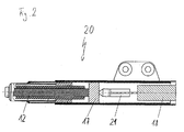
- Fig. 2 shows a device 20, which instead of the spring 16 Fig. 1 as a further elastic biasing device a pneumatic cylinder 21 has.
- the pneumatic cylinder 21 serves also the bias of the vibrator 12 and serves together with the masses 17 and 18 balancing the dynamic Reaction forces.
- a pneumatic cylinder can also be used, the bias is variable.
- the spring 16 or the pneumatic cylinder 21 also the other Components known to those skilled in the art, the preload of which can be adjusted or is not adjustable, can be used.
- the device according to the invention is advantageously suitable for any forms of excitation vibrations depending on the application to create. They are pulse-like stimuli like one Explosive excitation or hammer blow seismic possible. alternative are time-limited vibrations with predetermined amplitude and / or frequency profiles can be excited. It can also be repeated Single pulses or waveforms are generated through the use of the magnetostrictive vibrator 12 reproducibly formed in the same way. For example, it can a 20-fold repetition to generate batch signals be provided.
Landscapes
- Engineering & Computer Science (AREA)
- Remote Sensing (AREA)
- Physics & Mathematics (AREA)
- Life Sciences & Earth Sciences (AREA)
- Acoustics & Sound (AREA)
- Environmental & Geological Engineering (AREA)
- Geology (AREA)
- General Life Sciences & Earth Sciences (AREA)
- General Physics & Mathematics (AREA)
- Geophysics (AREA)
- Mechanical Engineering (AREA)
- Geophysics And Detection Of Objects (AREA)
- Apparatuses For Generation Of Mechanical Vibrations (AREA)
- General Electrical Machinery Utilizing Piezoelectricity, Electrostriction Or Magnetostriction (AREA)
Abstract
Description
Die Erfindung betrifft eine Vorrichtung und ein Verfahren zur Erzeugung mechanischer Schwingungen in einem festen Material, insbesondere in Festgestein, mit einem in einem Gehäuse angeordneten, elektrisch angetriebenen Schwingungsgeber.The invention relates to an apparatus and a method for Generation of mechanical vibrations in a solid material, in particular in solid rock, with one arranged in a housing, electrically driven vibrator.
Bisher allgemein bekannte Verfahren zur Erzeugung mechanischer Schwingungen in Festgestein z. B. für geophysikalische Untersuchungen basieren auf der Auslösung einer Sprengung. Diese Verfahren haben jedoch den Nachteil, dass sie eine Unterbrechung von Betriebs- oder Produktionsabläufen bedingen. Ebenfalls aus der Praxis bekannte sogenannte LKW-Schwinger arbeiten mit einem auf einem Fahrzeug angebrachten Schwingungsgenerator. Diese Systeme weisen ein großes Gewicht auf und sind beispielsweise in engen Tunneln wegen ihrer großen Abmessungen nicht einsetzbar. Ein genereller Nachteil der bisher bekannten, für feste Materialien eingesetzten Vorrichtungen besteht darin, dass die Signalform weder variierbar noch reproduzierbar ist. Auch werden diese Verfahren durch Störsignale, die sich in der näheren Umgebung der Signalquelle befinden, leicht beeinflusst.Hitherto well-known methods for generating mechanical Vibrations in hard rock z. B. for geophysical surveys are based on the triggering of an explosion. This procedure However, they have the disadvantage of being an interruption of operational or production processes. Also from so-called truck vibrators known in practice work with one vibration generator mounted on a vehicle. These systems have a large weight and are for example in narrow tunnels cannot be used due to their large dimensions. A general disadvantage of the previously known, for solid materials Devices used is that the waveform is neither variable nor reproducible. These too Procedure due to interference signals that are in the vicinity of the signal source are slightly influenced.
Die DE 199 44 032 A1 beschreibt eine Vorrichtung und ein Verfahren zur Erzeugung seismischer Schwingungen, wobei eine Schlagmasse von einer Antriebseinrichtung hin- und herbewegt wird. Nachteilig bei dieser Vorrichtung ist jedoch, dass sie eine breitbandige Anregung erzeugt und dass für eine hohe Eindringtiefe eine hohe Leistung erforderlich ist. Außerdem sind die mechanischen Bauteile im dauerhaften Betrieb verschleiß- und störanfällig. Sie erfordern somit einen relativ hohen Wartungsaufwand. DE 199 44 032 A1 describes an apparatus and a method to generate seismic vibrations, using an impact mass is moved back and forth by a drive device. A disadvantage of this device, however, is that it is a generates broadband excitation and that for a high penetration depth high performance is required. In addition, the mechanical Components in permanent operation susceptible to wear and failure. They therefore require a relatively high level of maintenance.
Andere aus der Praxis bekannte Verfahren arbeiten mit einem pneumatisch angetriebenen Hammer. Diese Vorrichtungen liefern jedoch ebenfalls Signale mit einer relativ großen Bandbreite. Ferner ist hier für ein tiefes Eindringen des Signals in das zu untersuchende Material eine hohe Leistung erforderlich. Auch ist der mechanische Aufbau solcher pneumatisch angetriebenen Hämmer bei ständigem Betrieb sehr störanfällig.Other methods known from practice work with one pneumatically driven hammer. These devices deliver however also signals with a relatively large bandwidth. It is also here for a deep penetration of the signal investigative material required high performance. Is too the mechanical structure of such pneumatically driven hammers very susceptible to faults during continuous operation.
Aus der Praxis sind elektrodynamische Schwingungsgeber bekannt, die mit hin- und herschwingenden Massen arbeiten, wobei diese Schwingungsgeber jedoch nur eine geringe Leistung liefern. Sie sind somit nicht für Festgestein geeignet, sondern nur für Lockerböden und wassergesättigte Böden.Electrodynamic vibration transmitters are known in practice, who work with oscillating masses, whereby these Vibration transmitters, however, only deliver a low output. she are therefore not suitable for solid rock, but only for loose floors and water-saturated soils.
Cutler et al. beschreiben im "Sandia Report" (Sand 97-0944, UC 403, April 1997) eine seismische Bohrlochquelle, die einen magnetostriktiven Schwingungsgeber aufweist. Diese Quelle wird zum Betrieb seitlich an eine Bohrlochwand geklammert, um vertikal polarisierte Scherwellen im umgebenden Gestein zu erzeugen. Dieses System besitzt einen beschränkten Anwendungsbereich zur Schwingungserzeugung in engen Bohrlöchern. Es ist beispielsweise nicht für Gebirgserkundungen im Tunnel geeignet. Die WO 99/39846 beschreibt eine auf dem im "Sandia Report" genannten Prinzip beruhende Vorrichtung zur Erkundung von Öl- und Gasspeicherlagerstätten. Diese Vorrichtung strahlt Kompressionswellen seitlich ab und eignet sich somit ebenfalls nicht zur Gebirgserkundung im Tunnel.Cutler et al. describe in the "Sandia Report" (Sand 97-0944, UC 403, April 1997) a seismic borehole source, the one has magnetostrictive vibrators. This source will clamped to the side of a borehole wall to operate vertically to generate polarized shear waves in the surrounding rock. This system has a limited scope for Vibration generation in narrow boreholes. For example it is not suitable for exploring the mountains in the tunnel. WO 99/39846 describes a principle based on the "Sandia Report" Device for exploring oil and gas storage deposits. This device emits compression waves laterally and is therefore also not suitable for exploring the mountains in the Tunnel.
Die Erfindung hat die Aufgabe, eine Vorrichtung der eingangs genannten Art dahingehend zu verbessern, dass die o.g. Nachteile vermieden werden und die erzeugten Signale variierbar und reproduzierbar sind. Die Aufgabe der Erfindung ist es auch, ein verbessertes Verfahren zur Schwingungserzeugung insbesondere für geophysikalische Untersuchungen anzugeben. The invention has for its object a device of the type mentioned Way to improve that the above disadvantage are avoided and the signals generated are variable and reproducible are. The object of the invention is also an improved Process for generating vibrations in particular for to provide geophysical surveys.
Diese Aufgabe wird durch eine Vorrichtung gemäß Anspruch 1 und
durch ein Verfahren gemäß Anspruch 14 gelöst. Vorteilhafte Ausführungsformen
und Anwendungen der Erfindung ergeben sich aus
den abhängigen Ansprüchen.This object is achieved by a device according to claim 1 and
solved by a method according to
Die Grundidee der Erfindung ist es, insbesondere als Signalgenerator für geophysikalische Untersuchungen eine Vorrichtung zur Erzeugung mechanischer Schwingungen in einem festen Material mit einem elektrisch angetriebenen Schwingungserzeuger, der ein axial wirkender, magnetostriktiver Schwingungsgeber ist, und mit einer Vorspanneinrichtung bereitzustellen, mit der der Schwingungserzeuger relativ zum Gehäuse und zum festen Material mit einem vorbestimmten, einstellbaren Anpressdruck angeordnet werden kann. Der magnetostriktive Schwingungsgeber ermöglicht die Erzeugung von Anregungsschwingungen mit einstellbaren, variierbaren und reproduzierbaren Parametern, so dass insbesondere eine verbesserte Trennung von Störsignalen möglich sind. Ferner erzeugt die Vorrichtung Kompressionswellen (akustische Wellen), die sich in Längsrichtung der Vorrichtung ausbreiten, weshalb sie besonders gut zur Untersuchung von Felsgestein geeignet sind. Vorteilhafterweise handelt es sich bei dem magnetostriktiven Schwingungsgeber um ein Bauteil mit verhältnismäßig geringer Masse. Somit müssen mit der erfindungsgemäßen Vorrichtung nicht mehr große Massen in Schwingung versetzt werden. Der Wirkungsgrad der gesamten Vorrichtung wird durch den Wegfall großer hin- und herbewegter Massen erheblich verbessert. Ferner sind die durch die Verwendung mechanischer Bauteile verursachte Störanfälligkeit und der Verschleiß erheblich reduziert, wodurch ein wirtschaftlicher Einsatz auch über lange Einsatzdauern hinweg sichergestellt ist. Ein besonderer Vorteil des erfindungsgemäß verwendeten Schwingungsgebers besteht in der Schwingungserzeugung mit vergleichsweise geringer Frequenzbandbreite. Im Unterschied zu herkömmlichen Systemen ist erfindungsgemäß bei geringerer Leistung eine höhere Eindringtiefe erzielbar. Die erfindungsgemäß vorgesehene Vorspanneinrichtung besitzt den Vorteil, dass der Schwingungserzeuger bei der Schwingungsanregung laufend in mechanischem Kontakt mit dem festen Material bleibt und die erzeugten Schwingungen effektiv in das Material übertragen werden.The basic idea of the invention is, in particular, as a signal generator a device for geophysical surveys Generation of mechanical vibrations in a solid material with an electrically driven vibrator that is axially effective, magnetostrictive vibrator, and with to provide a biasing device with which the vibration generator relative to the housing and the solid material a predetermined, adjustable contact pressure can be arranged can. The magnetostrictive vibrator enables that Generation of excitation vibrations with adjustable, variable and reproducible parameters, so that in particular a improved separation of interference signals are possible. Also generated the device compression waves (acoustic waves), which spread in the longitudinal direction of the device, which is why they are particularly well suited for the study of rock are. The magnetostrictive is advantageously used Vibration sensor around a component with a relatively low Dimensions. Thus, the device according to the invention does not have to more large masses are vibrated. The efficiency the entire device is eliminated by eliminating large and masses moved considerably improved. Furthermore, the susceptibility to failure caused by the use of mechanical components and significantly reduces wear, creating a economical use even over long periods of use is ensured. A particular advantage of the invention Vibration generator used consists in the generation of vibrations with a comparatively small frequency bandwidth. The difference to conventional systems is less according to the invention Performance a higher penetration depth can be achieved. The invention provided biasing device has the advantage that the vibration generator is continuously active when vibrating remains in mechanical contact with the solid material and the generated vibrations are effectively transferred into the material.
Wenn die Amplitude durch eine vorbestimmte Einstellung der Leistung entsprechend dem zu untersuchenden Material ausgewählt wird und/oder die Frequenz und/oder der Frequenzverlauf im Rahmen einer dynamischen Messung variiert werden, ist vorteilhafterweise eine verbesserte Trennung von Störsignalen möglich. Besonders gute Ergebnisse erzielt man im Frequenzbereich zwischen 0,2 kHz und 2 kHz.If the amplitude by a predetermined setting of the power is selected according to the material to be examined and / or the frequency and / or the frequency response in the context of a dynamic measurement is advantageous improved separation of interference signals possible. Especially good results are achieved in the frequency range between 0.2 kHz and 2 kHz.
Werden mit der Vorrichtung durch mehrfaches Abstrahlen und empfängerseitiges Überlagern (Übereinanderlegen, Addieren) der vom untersuchten Material rückgestreuten Schwingungs-Signale sogenannte Stapelsignale erzeugt, dann kann das Signal-Rausch-Verhältnis weiter verringert werden.Are with the device by multiple blasting and receiver side Superimposing (superimposing, adding) the from investigated material so-called backscattered vibration signals Batch signals generated, then the signal-to-noise ratio can be further reduced.
Gemäß einer bevorzugten Ausführungsform der Erfindung ist am Gehäuse der Vorrichtung zur Schwingungserzeugung an der dem festen Material zugewandten Seite eine Übertragungseinrichtung zur Einleitung der erzeugten Schwingungen in das feste Material angeordnet. Dies besitzt den Vorteil einer verbesserten und störungsärmeren Übertragung der vom Schwingungsgeber erzeugten Schwingungen auf das zu untersuchende Material, wobei gleichzeitig der hochwertige magnetostriktive Schwingungsgeber mechanisch geschützt wird.According to a preferred embodiment of the invention is on Housing of the device for generating vibrations on the fixed Material facing side a transmission device for Initiation of the generated vibrations arranged in the solid material. This has the advantage of an improved and less interference Transmission of those generated by the vibrator Vibrations on the material to be examined, at the same time the high-quality magnetostrictive vibrator mechanically is protected.
An der Übertragungseinrichtung kann vorteilhafterweise ein Schwingungsaufnehmer angebracht sein, mit dem die erzeugten Schwingungen detektiert werden können. Der Schwingungsaufnehmer kann Bezugssignale und/oder Triggersignale für die Auswertung von aus dem festen Material rückgestreuten Schwingungen liefern. A can advantageously be on the transmission device Vibration sensor can be attached with which the generated Vibrations can be detected. The vibration sensor can reference signals and / or trigger signals for evaluation of vibrations backscattered from the solid material.
Vorteilhafterweise kann die erfindungsgemäße Vorrichtung tragbar gebildet sein, so dass sie von einer Person jederzeit unabhängig von zusätzlichen Beförderungseinrichtungen an jeden beliebigen Ort getragen werden kann.The device according to the invention can advantageously be portable be educated so that they are independent of one person at any time from additional transportation facilities to any Place can be worn.
Zur Schwingungserzeugung in einem zu untersuchenden Material, insbesondere in Festgestein, wird die erfindungsgemäße Vorrichtung mit einem vorbestimmten Anpressdruck an das Material gedrückt. Vorteilhafterweise kann sie hierzu mit einem Gestell an einer Arbeitsmaschine angebracht sein, die das Widerlager für den Anpressdruck bilden. Wenn die Vorrichtung verschiebbar und/oder schwenkbar mit dem Gestell, der Baumaschine oder dem Bagger oder dergleichen verbunden ist, ermöglicht dies eine optimale Anpressung der Vorrichtung gegen das zu untersuchende Material.For generating vibrations in a material to be examined, especially in hard rock, the device according to the invention pressed against the material with a predetermined contact pressure. For this purpose, it can advantageously be provided with a frame be attached to a machine that the abutment for form the contact pressure. When the device is slidable and / or pivotable with the frame, the construction machine or the Excavator or the like is connected, this enables optimal Pressing the device against the material to be examined.
Zur Feineinstellung des Anpressdrucks der Vorrichtung gegen das zu untersuchende Material kann das Gehäuse teleskopartig auseinander- und zusammenschiebbar sein. Ferner ist sie mit einer Feder und/oder einem Pneumatikzylinder ausgestattet, so dass der Schwingungsgeber optimal vorgespannt wird. Der Pneumatikzylinder kann außerdem zur Verschiebung und Positionierung der Übertragungseinrichtung dienen.For fine adjustment of the contact pressure of the device against the Material to be examined can be telescopically separated from the housing. and be collapsible. It is also with a spring and / or a pneumatic cylinder, so that the Vibration transmitter is optimally biased. The pneumatic cylinder can also be used to move and position the transmission device serve.
Um die dynamischen Reaktions- und Vorspannkräfte auszugleichen, kann die Vorrichtung mit mindestens einer Ausgleichsmasse versehen sein, wobei die mindestens eine Ausgleichsmasse zur Verstärkung des Ausgleichseffektes mit mindestens einer Feder oder mindestens einem Pneumatikzylinder verbunden sein kann.To balance the dynamic reaction and preload forces, can provide the device with at least one leveling compound be, the at least one balancing mass for reinforcement the compensating effect with at least one spring or at least can be connected to a pneumatic cylinder.
Die Vorrichtung kann zur Optimierung der Anregung des zu untersuchenden Materials ein Längenmesssystem, ggf. mit einer Führungseinrichtung, aufweisen. Das Längenmesssystem hilft, unerwünschte und für den Schwingungsgeber schädliche Betriebszustände zu vermeiden, so dass die Vorrichtung nicht bei nicht auf das zu untersuchende Material aufgesetzter Übertragungseinrichtung oder nicht mit unzureichender Vorspannung des Schwingungsgebers betrieben wird. Außerdem gestattet das Längenmesssystem eine Steuerung der Amplitude der Anregungsschwingungen.The device can be used to optimize the excitation of the test item Material a length measuring system, possibly with a guide device, exhibit. The length measurement system helps unwanted and operating conditions that are harmful to the vibrator to avoid so that the device is not at not on the material to be examined mounted transmission device or not with insufficient preload on the vibration sensor is operated. The length measuring system also allows one Control of the amplitude of the excitation vibrations.
Gegenstand der Erfindung ist auch ein Verfahren zur Erzeugung mechanischer Schwingungen in einem festen Material, insbesondere in Festgestein, mit einer erfindungsgemäßen Vorrichtung, gekennzeichnet durch folgende Schritte:
- Anlegen der Vorrichtung an das zu untersuchende feste Material,
- Vorspannen des Schwingungsgebers, und
- Aktivieren des Schwingungsgebers.
- Placing the device on the solid material to be examined,
- Preloading the vibrator, and
- Activate the vibrator.
Weitere Vorteile und Einzelheiten der Erfindung ergeben sich aus der folgenden Beschreibung der beigefügten Zeichnungen. Es zeigen:
- Fig. 1
- einen Längsschnitt durch eine erste Ausführungsform einer erfindungsgemäßen Vorrichtung; und
- Fig. 2
- einen Längsschnitt durch eine zweite Ausführungsform einer erfindungsgemäßen Vorrichtung.
- Fig. 1
- a longitudinal section through a first embodiment of a device according to the invention; and
- Fig. 2
- a longitudinal section through a second embodiment of a device according to the invention.
Fig. 1 zeigt eine Vorrichtung 10 zur Erzeugung mechanischer
Schwingungen in einem festen Material, insbesondere Festgestein.
Sie weist zur Schwingungserzeugung einen in einem rohrförmigen
Gehäuse 11 angeordneten, in einer Spule 13 fixierten magnetostriktiven
Schwingungsgeber 12 auf. Der magnetostriktive
Schwingungsgeber ist eine an sich bekannte, kommerziell verfügbare
Komponente. Er besteht aus einem magnetostriktiven Material,
das unter Einwirkung eines äußeren Magnetfeldes eine materialspezifische
Längenänderung und/oder Verspannung bildet. Der
Schwingungsgeber besitzt vorzugsweise die Form eines Stabes oder
Zylinders mit einer Länge von z. B. 30 cm und einem Durchmesser
von z. B. 50 mm. Unter der Einwirkung eines von der Spule 13
erzeugten periodisch veränderlichen Magnetfelds dehnt sich der
axial angeordnete magnetostriktive Schwingungsgeber 12 periodisch
aus und geht wieder auf seine Anfangslänge zurück. Wird
die Vorrichtung 10 mit einer Übertragungseinrichtung 14 auf das
zu untersuchende Material, beispielsweise Festgestein, aufgelegt,
so regt der Schwingungsgeber 12 mittels der Übertragungseinrichtung
14 das zu untersuchende Material zum Schwingen an.
Die Schwingungsanregung erfolgt axial, d. h. entsprechend der
Längsrichtung der Vorrichtung 10.Fig. 1 shows a
Da der magnetostriktive Schwingungsgeber 12 nur eine relativ
kleine Masse aufweist, die sich nur um verhältnismäßig kleine
Amplituden verlängert, kann der Schwingungsgeber 12 auch mit
sehr hohen Frequenzen schwingen, wozu bisher bekannte gattungsgemäße
Vorrichtungen, die mit hin- und herschwingenden Massen
arbeiten, nicht fähig sind. Somit kann der Schwingungsgeber 12
ein Frequenzband von sehr hohen bis zu niedrigen Frequenzen
durchlaufen, wobei auch noch die Amplitude durch Einstellung einer
Leistungseinheit 15 auf einen bestimmten Wert beliebig variierbar
ist. Folglich kann der Schwingungsgeber 12 diskrete Einzelsignale
einer bestimmten Frequenz oder auch kontinuierliche
Signalfolgen über einen ausgewählten Frequenzbereich erzeugen.
Die Einstellung definierter Frequenzen oder Frequenzfolgen
"sweeps" oder ("chirps") besitzt den Vorteil, dass bei der Analyse
der Reaktion des untersuchten Materials auf die Schwingungsanregung
Störsignale besser erkannt und unterdrückt werden
können.Since the
Der Schwingungsgeber 12 und die Spule 13 sind in einem Gehäuse
11 untergebracht, das einerseits die Übertragungseinrichtung 14
trägt und andererseits mit einem Grundkörper verbunden ist, der
eine Masse 18 und die Leistungseinheit 15 enthält. Das Gehäuse
11 ist elastisch und verschiebbar am Grundkörper befestigt, der
über eine Befestigungseinrichtung 102 an einer (äußeren)
Vorspanneinrichtung (nicht dargestellt), z. B. einem Gestell,
einer ggf. mobilen Arbeitsmaschine, einer Tunnelbohrmaschine,
einem Bagger, einer Seilverspannung oder dgl. angebracht ist,
die ein Widerlager für die Vorrichtung 10 bildet. Die Vorspanneinrichtung
ist ortsfest in der Umgebung des Ortes der Schwingungsanregung
positioniert und dient der Aufbringung des Anpressdruckes
während der Schwingungsanregung. Die Seilverspannung
umfasst beispielsweise Anker und ein Drahtseil, die am Gestein
und der Befestigungseinrichtung 102 angebracht sind und
mit denen die Vorrichtung 10 mit einer vorbestimmten Kraft gegen
das Gestein pressbar ist.The
Durch eine ebenfalls als (innere) Vorspanneinrichtung wirkende
Feder 16 wird der Schwingungsgeber 12 mit der Übertragungseinrichtung
14 elastisch gegen das hier nicht näher dargestellte
Festgestein gedrückt und somit relativ zum Grundkörper vorgespannt,
um Beschädigungen des Schwingungsgebers 12 bei nicht angepresster
oder nicht genügend angepresster Vorrichtung 10 zu
vermeiden. Aus dem selben Grund weist das Gehäuse 11 zwei teleskopartig
ineinandergesteckte Gehäuseteile 19 und 100 auf. Somit
kann durch entsprechendes Auseinanderfahren der Gehäuseteile
19 und 100 eine optimale Vorspannung des Schwingungsgebers 12
erzielt werden.By an also acting as an (inner)
Ein Längenmesssystem 101 dient ebenfalls der Vermeidung einer
Inbetriebnahme der Vorrichtung 10 bei nicht vorgespanntem oder
nicht genügend vorgespanntem Schwingungsgeber 12. Ferner gestattet
das Längenmesssystem 101 eine Steuerung der Schwingungsamplitude.
Massen 17 und 18 fangen zusammen mit der Feder 16 die im
Betrieb entstehenden dynamischen Reaktionskräfte der Vorrichtung
10 ab. Das Längenmesssystem 101 ist gegebenenfalls mit einer
Führungseinrichtung für die Gehäuseteile ausgestattet.A
An der Übertragungseinrichtung kann ein Schwingungsaufnehmer (nicht dargestellt) angebracht sein, der z. B. mindestens einen piezoelektrischen Schwingungssensor umfasst. Mit dem Schwingungssensor werden beispielsweise die Frequenz(en) oder die Amplitude(n) der erzeugten Schwingungen erfasst.A vibration sensor can be attached to the transmission device (not shown) attached, the z. B. at least one includes piezoelectric vibration sensor. With the vibration sensor for example, the frequency (s) or the amplitude (s) of the vibrations generated.
Am Ende des Gehäuses 11 kann ein weiterer Schwingungsaufnehmer
angebracht sein, der die bei der Schwingungserzeugung am Gehäuse
entstehenden Schwingungen erfasst. Diese Schwingungen sind durch
eine komplexe Überlagerung von Resonanzen des Gehäuses geprägt,
sie können bei der Auswertung der aus dem Gestein rückgestreuten
Schwingungen berücksichtigt werden.At the end of the
Fig. 2 zeigt eine Vorrichtung 20, die statt der Feder 16 aus
Fig. 1 als weitere elastische Vorspanneinrichtung einen Pneumatikzylinder
21 aufweist. Der Pneumatikzylinder 21 dient dabei
ebenfalls der Vorspannung des Schwingungsgebers 12 und dient zusammen
mit den Massen 17 und 18 dem Ausgleich der dynamischen
Reaktionskräfte. Alternativ ist auch ein Pneumatikzylinder einsetzbar,
dessen Vorspannung variierbar ist. Außerdem sind statt
der Feder 16 oder des Pneumatikzylinders 21 auch andere dem
Fachmann bekannte Bauteile, deren Vorspannung einstellbar oder
nicht einstellbar ist, einsetzbar.Fig. 2 shows a
Die erfindungsgemäße Vorrichtung ist vorteilhafterweise dazu geeignet,
anwendungsabhängig beliebige Formen von Anregungsschwingungen
zu erzeugen. Es sind pulsförmige Anregungen wie bei einer
Sprenganregung oder der Hammerschlagseismik möglich. Alternativ
sind zeitlich begrenzte Schwingungen mit vorbestimmten Amplituden-
und/oder Frequenzverläufen anregbar. Es können auch mehrfach
Einzelpulse oder Schwingungsverläufe erzeugt werden, die
durch die Verwendung des magnetostriktiven Schwingungsgebers 12
reproduzierbar gleichartig gebildet werden. Es kann beispielsweise
eine 20fache Wiederholung zur Erzeugung von Stapelsignalen
vorgesehen sein. The device according to the invention is advantageously suitable for
any forms of excitation vibrations depending on the application
to create. They are pulse-like stimuli like one
Explosive excitation or hammer blow seismic possible. alternative
are time-limited vibrations with predetermined amplitude
and / or frequency profiles can be excited. It can also be repeated
Single pulses or waveforms are generated
through the use of the
Die in der vorstehenden Beschreibung, den Zeichnungen und den Ansprüchen offenbarten Merkmale der Erfindung können sowohl einzeln als auch in beliebiger Kombination für die Verwirklichung der Erfindung in ihren verschiedenen Ausgestaltungen von Bedeutung sein.The in the above description, the drawings and the Features of the invention disclosed claims can be both individually as well as in any combination for the realization the invention in its various configurations of importance his.
Claims (18)
Applications Claiming Priority (2)
| Application Number | Priority Date | Filing Date | Title |
|---|---|---|---|
| DE10141518A DE10141518B4 (en) | 2001-08-24 | 2001-08-24 | Device for generating mechanical vibrations in a solid material |
| DE10141518 | 2001-08-24 |
Publications (3)
| Publication Number | Publication Date |
|---|---|
| EP1288681A2 true EP1288681A2 (en) | 2003-03-05 |
| EP1288681A3 EP1288681A3 (en) | 2004-05-06 |
| EP1288681B1 EP1288681B1 (en) | 2009-02-25 |
Family
ID=7696485
Family Applications (1)
| Application Number | Title | Priority Date | Filing Date |
|---|---|---|---|
| EP02018934A Expired - Lifetime EP1288681B1 (en) | 2001-08-24 | 2002-08-23 | Device and method for generating mechanical vibrations in rocks and use of said device |
Country Status (4)
| Country | Link |
|---|---|
| EP (1) | EP1288681B1 (en) |
| JP (1) | JP4216543B2 (en) |
| AT (1) | ATE423983T1 (en) |
| DE (1) | DE10141518B4 (en) |
Cited By (1)
| Publication number | Priority date | Publication date | Assignee | Title |
|---|---|---|---|---|
| CN110333295A (en) * | 2019-08-05 | 2019-10-15 | 河北中核岩土工程有限责任公司 | Ground core sample wave velocity testing system and method |
Families Citing this family (1)
| Publication number | Priority date | Publication date | Assignee | Title |
|---|---|---|---|---|
| CN103675892B (en) * | 2013-12-04 | 2016-08-31 | 中交四航工程研究院有限公司 | A kind of high time precision focus hammer |
Citations (5)
| Publication number | Priority date | Publication date | Assignee | Title |
|---|---|---|---|---|
| FR1132620A (en) * | 1955-07-28 | 1957-03-13 | Realisations Ultrasoniques Sa | Apparatus for examining and measuring distances in solids by means of elastic pulses |
| EP0569735A1 (en) * | 1992-04-23 | 1993-11-18 | Tetra Laval Holdings & Finance SA | An apparatus for sealing by surface fusion of mutually facing surfaces of thermoplastic materials or coatings, and the use of a giant magnetostrictive powder composite for this purpose |
| US5357063A (en) * | 1993-07-12 | 1994-10-18 | Battelle Memorial Institute | Method and apparatus for acoustic energy identification of objects buried in soil |
| US5852262A (en) * | 1995-09-28 | 1998-12-22 | Magnetic Pulse, Inc. | Acoustic formation logging tool with improved transmitter |
| EP1085347A2 (en) * | 1999-09-14 | 2001-03-21 | Geoforschungszentrum Potsdam | Apparatus and method for generating seismic vibrations |
Family Cites Families (4)
| Publication number | Priority date | Publication date | Assignee | Title |
|---|---|---|---|---|
| US1966446A (en) * | 1933-02-14 | 1934-07-17 | Harvey C Hayes | Impact tool |
| US2737639A (en) * | 1953-03-23 | 1956-03-06 | Socony Mobil Oil Co Inc | Electromechanical acoustic pulser |
| US6012521A (en) * | 1998-02-09 | 2000-01-11 | Etrema Products, Inc. | Downhole pressure wave generator and method for use thereof |
| JP2000121742A (en) * | 1998-10-14 | 2000-04-28 | Mitsubishi Electric Corp | Transmitter for transmitting excavation shell sound and method for transmitting excavation shell sound |
-
2001
- 2001-08-24 DE DE10141518A patent/DE10141518B4/en not_active Expired - Fee Related
-
2002
- 2002-08-23 JP JP2002243206A patent/JP4216543B2/en not_active Expired - Fee Related
- 2002-08-23 AT AT02018934T patent/ATE423983T1/en active
- 2002-08-23 EP EP02018934A patent/EP1288681B1/en not_active Expired - Lifetime
Patent Citations (5)
| Publication number | Priority date | Publication date | Assignee | Title |
|---|---|---|---|---|
| FR1132620A (en) * | 1955-07-28 | 1957-03-13 | Realisations Ultrasoniques Sa | Apparatus for examining and measuring distances in solids by means of elastic pulses |
| EP0569735A1 (en) * | 1992-04-23 | 1993-11-18 | Tetra Laval Holdings & Finance SA | An apparatus for sealing by surface fusion of mutually facing surfaces of thermoplastic materials or coatings, and the use of a giant magnetostrictive powder composite for this purpose |
| US5357063A (en) * | 1993-07-12 | 1994-10-18 | Battelle Memorial Institute | Method and apparatus for acoustic energy identification of objects buried in soil |
| US5852262A (en) * | 1995-09-28 | 1998-12-22 | Magnetic Pulse, Inc. | Acoustic formation logging tool with improved transmitter |
| EP1085347A2 (en) * | 1999-09-14 | 2001-03-21 | Geoforschungszentrum Potsdam | Apparatus and method for generating seismic vibrations |
Non-Patent Citations (1)
| Title |
|---|
| HOUQING Z ET AL: "Applications of Terfenol-D in China" JOURNAL OF ALLOYS AND COMPOUNDS, ELSEVIER SEQUOIA, LAUSANNE, CH, Bd. 258, 1. August 1997 (1997-08-01), Seiten 49-52, XP004160935 ISSN: 0925-8388 * |
Cited By (2)
| Publication number | Priority date | Publication date | Assignee | Title |
|---|---|---|---|---|
| CN110333295A (en) * | 2019-08-05 | 2019-10-15 | 河北中核岩土工程有限责任公司 | Ground core sample wave velocity testing system and method |
| CN110333295B (en) * | 2019-08-05 | 2024-03-26 | 河北中核岩土工程有限责任公司 | Rock-soil core sample wave speed testing system and method |
Also Published As
| Publication number | Publication date |
|---|---|
| EP1288681B1 (en) | 2009-02-25 |
| ATE423983T1 (en) | 2009-03-15 |
| DE10141518A1 (en) | 2003-03-13 |
| DE10141518B4 (en) | 2004-07-15 |
| JP4216543B2 (en) | 2009-01-28 |
| JP2003107165A (en) | 2003-04-09 |
| EP1288681A3 (en) | 2004-05-06 |
Similar Documents
| Publication | Publication Date | Title |
|---|---|---|
| DE102006009246B3 (en) | Preliminary surveying for tunnel building involves sensor arrangement with number of sensors distributed on tunnel wall receiving surface waves running from face of tunnel to sensors, using propagation model and transition time evaluation | |
| DE2745213A1 (en) | METHOD AND DEVICE FOR GENERATING AND TRANSMITTING SEISMIC SIGNALS | |
| EP1632637B1 (en) | Soil working tool and method for introducing a working element into the soil | |
| EP1085347B1 (en) | Apparatus and method for generating seismic vibrations | |
| EP1001134B1 (en) | Anchoring device with a seismic sensor | |
| DE19628769C2 (en) | Method and device for deep compaction of binding and non-binding compaction material | |
| EP1288681B1 (en) | Device and method for generating mechanical vibrations in rocks and use of said device | |
| EP3417951B1 (en) | Device and method for generating impact impulses or vibration of a construction machine | |
| DE1448550B2 (en) | Procedure of geophysical prospecting | |
| Chan | A laboratory investigation of shear wave velocity in stabilised soft soils. | |
| DE4233958C2 (en) | Method for determining the structure of rock | |
| DE19816157A1 (en) | Elastic wave exploration tool for boreholes | |
| DE3305189A1 (en) | Bore-hole probe | |
| DE102010019053A1 (en) | Compaction device i.e. vibration plate, for use in vibration machine for compaction of e.g. clay during construction of road, has evaluating device determining soil parameter for determining soil characteristics based on motion signal | |
| DE102004014722B3 (en) | Seismic source for geological and building investigations has oblique gas springs and separate flat transmission unit | |
| EP3369864A1 (en) | Method of detecting obstructions during the operation of a vibration driver | |
| DE19549250C1 (en) | Apparatus for location of explosive charge concealed in ground | |
| Grizi et al. | Understanding the Energy Transfer Mechanism in the Near Field of Impact Driven Piles | |
| EP0224635B1 (en) | Arrangement for sounding a rock formation | |
| DE1448671C (en) | Seismic method to determine the sound propagation times in the weathering zone of the ground | |
| DE2832078A1 (en) | Seismic energy source using vehicle-mounted hydraulic hammer - has rear axle weight transferred to hammer assembly to give good contact with ground | |
| EP1624153B1 (en) | Method for determining soil properties | |
| EP3708714B1 (en) | Securing device for securing a civil engineering element and civil engineering method | |
| RU2105998C1 (en) | Process of seismic microzoning | |
| EP1729150A2 (en) | Seismic source and method for creating seismic shear waves |
Legal Events
| Date | Code | Title | Description |
|---|---|---|---|
| PUAI | Public reference made under article 153(3) epc to a published international application that has entered the european phase |
Free format text: ORIGINAL CODE: 0009012 |
|
| AK | Designated contracting states |
Kind code of ref document: A2 Designated state(s): AT BE BG CH CY CZ DE DK EE ES FI FR GB GR IE IT LI LU MC NL PT SE SK TR |
|
| AX | Request for extension of the european patent |
Extension state: AL LT LV MK RO SI |
|
| PUAL | Search report despatched |
Free format text: ORIGINAL CODE: 0009013 |
|
| AK | Designated contracting states |
Kind code of ref document: A3 Designated state(s): AT BE BG CH CY CZ DE DK EE ES FI FR GB GR IE IT LI LU MC NL PT SE SK TR |
|
| AX | Request for extension of the european patent |
Extension state: AL LT LV MK RO SI |
|
| RIC1 | Information provided on ipc code assigned before grant |
Ipc: 7G 01V 1/145 A |
|
| 17P | Request for examination filed |
Effective date: 20040813 |
|
| AKX | Designation fees paid |
Designated state(s): AT CH DE FR IT LI |
|
| RTI1 | Title (correction) |
Free format text: DEVICE AND METHOD FOR GENERATING MECHANICAL VIBRATIONS IN ROCKS AND USE OF SAID DEVICE |
|
| GRAP | Despatch of communication of intention to grant a patent |
Free format text: ORIGINAL CODE: EPIDOSNIGR1 |
|
| GRAS | Grant fee paid |
Free format text: ORIGINAL CODE: EPIDOSNIGR3 |
|
| GRAA | (expected) grant |
Free format text: ORIGINAL CODE: 0009210 |
|
| RBV | Designated contracting states (corrected) |
Designated state(s): AT CH FR IT LI |
|
| AK | Designated contracting states |
Kind code of ref document: B1 Designated state(s): AT CH FR IT LI |
|
| REG | Reference to a national code |
Ref country code: CH Ref legal event code: EP |
|
| REG | Reference to a national code |
Ref country code: DE Ref legal event code: 8566 |
|
| REG | Reference to a national code |
Ref country code: CH Ref legal event code: NV Representative=s name: RITSCHER & PARTNER AG |
|
| RAP2 | Party data changed (patent owner data changed or rights of a patent transferred) |
Owner name: HELMHOLTZ-ZENTRUM POTSDAM DEUTSCHES GEOFORSCHUNGSZ |
|
| PLBE | No opposition filed within time limit |
Free format text: ORIGINAL CODE: 0009261 |
|
| STAA | Information on the status of an ep patent application or granted ep patent |
Free format text: STATUS: NO OPPOSITION FILED WITHIN TIME LIMIT |
|
| 26N | No opposition filed |
Effective date: 20091126 |
|
| PGFP | Annual fee paid to national office [announced via postgrant information from national office to epo] |
Ref country code: CH Payment date: 20110726 Year of fee payment: 10 |
|
| PGFP | Annual fee paid to national office [announced via postgrant information from national office to epo] |
Ref country code: AT Payment date: 20110822 Year of fee payment: 10 Ref country code: FR Payment date: 20110902 Year of fee payment: 10 |
|
| PGFP | Annual fee paid to national office [announced via postgrant information from national office to epo] |
Ref country code: IT Payment date: 20110824 Year of fee payment: 10 |
|
| REG | Reference to a national code |
Ref country code: CH Ref legal event code: PL |
|
| REG | Reference to a national code |
Ref country code: AT Ref legal event code: MM01 Ref document number: 423983 Country of ref document: AT Kind code of ref document: T Effective date: 20120823 |
|
| PG25 | Lapsed in a contracting state [announced via postgrant information from national office to epo] |
Ref country code: LI Free format text: LAPSE BECAUSE OF NON-PAYMENT OF DUE FEES Effective date: 20120831 Ref country code: CH Free format text: LAPSE BECAUSE OF NON-PAYMENT OF DUE FEES Effective date: 20120831 |
|
| REG | Reference to a national code |
Ref country code: FR Ref legal event code: ST Effective date: 20130430 |
|
| PG25 | Lapsed in a contracting state [announced via postgrant information from national office to epo] |
Ref country code: IT Free format text: LAPSE BECAUSE OF NON-PAYMENT OF DUE FEES Effective date: 20120823 |
|
| PG25 | Lapsed in a contracting state [announced via postgrant information from national office to epo] |
Ref country code: AT Free format text: LAPSE BECAUSE OF NON-PAYMENT OF DUE FEES Effective date: 20120823 |
|
| PG25 | Lapsed in a contracting state [announced via postgrant information from national office to epo] |
Ref country code: FR Free format text: LAPSE BECAUSE OF NON-PAYMENT OF DUE FEES Effective date: 20120831 |