EP1288541A2 - Mechanical sealing device - Google Patents
Mechanical sealing device Download PDFInfo
- Publication number
- EP1288541A2 EP1288541A2 EP02256061A EP02256061A EP1288541A2 EP 1288541 A2 EP1288541 A2 EP 1288541A2 EP 02256061 A EP02256061 A EP 02256061A EP 02256061 A EP02256061 A EP 02256061A EP 1288541 A2 EP1288541 A2 EP 1288541A2
- Authority
- EP
- European Patent Office
- Prior art keywords
- seal
- face
- seal ring
- shaft
- ring
- Prior art date
- Legal status (The legal status is an assumption and is not a legal conclusion. Google has not performed a legal analysis and makes no representation as to the accuracy of the status listed.)
- Granted
Links
Images


Classifications
-
- F—MECHANICAL ENGINEERING; LIGHTING; HEATING; WEAPONS; BLASTING
- F16—ENGINEERING ELEMENTS AND UNITS; GENERAL MEASURES FOR PRODUCING AND MAINTAINING EFFECTIVE FUNCTIONING OF MACHINES OR INSTALLATIONS; THERMAL INSULATION IN GENERAL
- F16J—PISTONS; CYLINDERS; SEALINGS
- F16J15/00—Sealings
- F16J15/16—Sealings between relatively-moving surfaces
- F16J15/34—Sealings between relatively-moving surfaces with slip-ring pressed against a more or less radial face on one member
- F16J15/3464—Mounting of the seal
- F16J15/348—Pre-assembled seals, e.g. cartridge seals
-
- F—MECHANICAL ENGINEERING; LIGHTING; HEATING; WEAPONS; BLASTING
- F16—ENGINEERING ELEMENTS AND UNITS; GENERAL MEASURES FOR PRODUCING AND MAINTAINING EFFECTIVE FUNCTIONING OF MACHINES OR INSTALLATIONS; THERMAL INSULATION IN GENERAL
- F16J—PISTONS; CYLINDERS; SEALINGS
- F16J15/00—Sealings
- F16J15/16—Sealings between relatively-moving surfaces
- F16J15/34—Sealings between relatively-moving surfaces with slip-ring pressed against a more or less radial face on one member
- F16J15/3404—Sealings between relatively-moving surfaces with slip-ring pressed against a more or less radial face on one member and characterised by parts or details relating to lubrication, cooling or venting of the seal
Definitions
- This invention relates to a mechanical sealing device and particularly to the technical field of a cartridge type mechanical sealing device adapted to seal high viscosity fluid or slurry contained fluid and prevent solid matters contained in the fluid to be sealed from sticking on the components and clogging between the components.
- Fig. 5 is a half sectional view of the mechanical seal shown in Fig. 4 of US-A-4,290,611.
- the reference numeral 100 denotes a mechanical seal.
- the mechanical seal 100 is comprised of a pair of primary components so as to be attached to a rotary shaft 151 and then installed within a stuffing box 150 through fastening bolts 160.
- the mechanical seal 100 includes, as the primary components thereof, a liquid sealing device 101, a fist seal flange 110, a second seal flange 120 and a gas sealing device 121 that are arranged in order, from the inside of the stuffing box 150 toward the outside thereof, in the axial direction.
- the liquid sealing device 101 is mounted on the outer circumference of a sleeve 153 secured onto the rotary shaft 151 through a screw socket 152. Between the rotary shaft 151 and the sleeve 153 fitting thereto is disposed an O-ring 154 for sealing therebetween.
- a rotary seal ring 102 formed with a rotary seal face 103 is resiliently biased by a spring 105 through a U-shaped gasket 107 and a spacer 108.
- a stationary seal ring 112 having a stationary seal face 113 in contact with the rotary seal face 103 is fitted to the inner circumference of the first seal flange 110 through an O-ring 116. Further, at least one pin 115 secured to the stationary seal ring 112 engages a groove provided in the inner circumference of the first seal flange 110 to engage the stationary seal ring 112 with the first seal flange 110.
- a gas-sealing device 121 is installed inside of the inner circumference of the second seal flange 120 coupled with the first seal flange 110.
- the gas-sealing device 121 is provided with a drive sleeve 125 that is secured to the sleeve 153 through at setscrew 126.
- a second rotary seal ring 122 having a second rotary seal face 123 is fitted in the drive sleeve 125 to slide therein.
- One end of a fluid passage formed in the second rotary seal ring 122 for creating dynamic pressure is opened at the second rotary seal face 123.
- a second stationary seal ring 132 having a second stationary seal face 133 in close contact with the second rotary seal face 123 of the second rotary seal ring 122 is fitted to the inner circumference of the second seal flange 120 through an O-ring 136.
- the second stationary seal face 133 are formed a plurality of grooves for creating dynamic pressure, in cooperation with the second rotary seal face 123.
- the second rotary seal ring 122 is resiliently biased by a coil spring 127 toward the second stationary seal ring 132 side.
- the second seal flange 120 is provided with a drain tap 128 for draining liquid that leaked from the liquid sealing device 101. Also, in the stuffing box 150 is provided a flushing port 158 for washing the liquid sealing device 101 using liquid ejected therefrom.
- the mechanical seal 100 is assembled to the rotary shaft 151 and then the assembly is inserted and installed inside of inner circumferential surface 156 of the stuffing box 150.
- the mechanical seal 100 constituted as described is installed, through the sleeve 153, in a space 157 that is formed between the outer circumferential surface of the rotary shaft 151 and the inner circumferential surface 156 of the stuffing box 150.
- the space 157 is required of a size enough to contain the sleeve 153 and the liquid sealing device 101.
- the increase of the diameter of the inner surface 156 of the stuffing box 150 is often limited due to structural conditions. Accordingly, the gap formed between the inner surface 156 of the stuffing box 150 and the liquid sealing device 101 will be small, which causes the flow of the sealed fluid to be worsened.
- the rotary seal face 103 and the stationary seal face 113 heated by sliding heat generation cannot be satisfactorily cooled. This causes the seal faces to be damaged.
- the fluid to be sealed is viscosity fluid or slurry contained fluid
- slurries contained in the fluid are apt to clog between the liquid sealing device 101 and the inner surface 156 of the stuffing box 150. This causes the cooling effect on both seal faces 103, 113 as well as the sealing ability thereof to worsen, resulting in sealed fluid leakages between the seal faces 103, 113.
- the technical problem to be solved by the invention is to provide a liquid sealing device that is arranged to be mounted outside of the stuffing box and the rotary shaft regardless of the structure of the stuffing box, for allowing the seal faces of the stationary and rotary seal rings sliding each other to be cooled and for preventing slurries in the sealed fluid or high viscosity fluid from sticking to cause the response to be deficient.
- Another technical problem to be solved is to easily wash off slurries contained in the sealed fluid or high viscosity fluid that sticks in the liquid sealing device and solidifies, especially wash the sliding faces of the seal rings at any time for maintaining good response of the seal rings to the surface pressure.
- a further technical problem to be solved is to provide a sealing device that is arranged to be mounted outside of the stuffing box and the rotary shaft regardless of the structure of the stuffing box, for allowing the distance between the opposing faces of the stationary and rotary seal rings to be enough to avoid any inverse affects from the slurry contained fluid and high viscosity fluid.
- a further yet technical problem to be solved is to provide a sealing device having a structure so that fixing pins or the like for preventing the rotation of the seal rings and springs that bias the seal rings are not inversely affected by the sealed fluid.
- a mechanical seal installed externally of a shaft and a device body through which the shaft passes, characterised by:
- the first seal ring In the mechanical seal as just defined, between the first seal ring and the shaft the first seal ring has a gap having a size enough for the sealed fluid to pass through, and the flushing port is in communication with the proximity of the radially inner side of the seal face. Accordingly, for the first seal ring biased by the resilient means, its all surfaces that contact the sealed fluid are washed by the fluid injected through the flushing port. Therefore, slurries in the sealed fluid and high viscosity fluid sticking on the first seal ring will not solidify thereon. In other words, since the sliding movement of the first seal ring is not blocked by such solid matters, the response to the surface pressure of the seal face can be exerted and the sealing effect be improved.
- the mechanical sealing device is installed within the attachment member that is installed externally to the device body, it is allowed to design the gap between the first ring seal and the shaft to be fully long. Accordingly, the sealed fluid can flow smoothly within the first seal ring. Further, high viscosity fluid or slurries are blocked to stick and solidify on the first seal ring, resulting in improvement of response of the first seal ring and exertion of sealing ability.
- An attachment groove may be formed between the first seal ring and the inner face of the attachment member fitting thereto and a third seal ring provided in the attachment groove; wherein the flushing port is opened at the inner surface, close to the attachment groove.
- the mechanical seal further comprises the third seal ring provided in the attachment groove formed between the first seal ring and the inner face of the attachment member and the flushing port is opened at the inner surface, close to the attachment groove, it can prevent the smooth of the first seal ring working from declining due to the slurries and other sticking between the third seal ring and the attachment groove. Therefore it is expected that the response of the surface pressure of the first seal ring improve.
- An annular blocking gasket may be retained with fluid tightness by the attachment member on the side opposing the attachment groove and fitted with fluid tight or with play, at the inner surface, to the shaft.
- the mechanical seal can wash the attachment groove fitting the third seal ring therein, the inner surface of the first seal ring and the seal surface of the first seal ring to change the inflow direction of fresh water by the annular blocking gasket when fresh water is introduced from the flushing port for quenching. And it can effectively prevent high viscosity fluid to be sealed from sticking to the first seal ring or from stopping the opening passage by sticking to a narrow opening. And it can effectively prevent the sealing ability from declining due to the impediment of the first seal ring working.
- a mechanical seal installed externally of a shaft and a device body (60) through which the shaft passes, characterised by:
- the attachment member includes an annular cooling passage formed to cover circumferentially over the seal face of the first seal ring fitting to the inner surface of the attachment member, a throttling face outward of the annular cooling groove is fitted with a play to the outer circumferential surface of the second seal ring, and the attachment member also includes a coolant passage in communication with the annular cooling groove. Accordingly, the raised temperature can be lowered by supplying a large volume of fresh water to directly cool the proximity of the seal faces heated with heat generation from relative sliding of the first and the second seal rings. It is therefore allowed that if both seal faces sliding each other are subject to sliding heat generation, they are effectively cooled to prevent from being damaged due to deformation thereof.
- the annular cooling groove may have a size that one side face of the annular cooling groove is formed radially and outwardly at the axially inner midpoint of the first seal ring spaced from the seal face as a centre and the other side face is formed radially and outwardly at the axially outer midpoint of the second seal ring.
- the annular cooling groove is formed at the axially seal face of the first seal ring and the second seal ring so as to cover all outside, it can cool effectively the first seal ring and second seal ring. Therefore it can prevent the seal face from transforming owing to generation of heat and it can show the ability of sealing of the seal face.
- the resilient means or a fixing pin of the first seal ring and the second seal ring may be located on the atmospheric airside, as compared to the seal face.
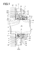
- Fig. 1 shows a mechanical sealing device 1 as a first embodiment.
- the mechanical sealing device 1 as a cartridge is installed on the device body (stuffing box) 60 and the external face of the rotary shaft 70.
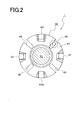
- Fig. 2 shows the mechanical sealing device 1 fitted to the rotary shaft 70 in Fig. 1 as seen in the axial direction.
- the mechanical sealing device 1 in Fig. 1 is installed by positioning a seal flange 30 that is fixed to the external face 61 of the device body 60 and a seal collar 50 to be fixedly fitted to the rotary shaft 70, using set plates 55.
- the seal flange (attachment component) 30 to be mounted to the device body 60 is, as shown in Fig. 2, configured to be an annular disk and has four fixing grooves 45 arranged along the circumference with equal spacing to each other.
- the seal flange 30 is attached to the device body 60 through the fixing grooves 45 with bolts 63.
- the inner circumferential surface of the seal flange 30 defines a fitting surface 31, an annular cooling groove 32 and a throttling face 33.
- the seal flange 30 is provided with two or three quenching liquid passages 40 arranged to be equally spaced along the outer circumferential surface, a flushing port 41, and quenching liquid drain ports 40A on the same circumferential surface.
- Each of the fluid passages 40 is formed so as to communicate with the annular cooling groove 32 in the inner circumferential surface, through a pipe thread portion for connecting an external piping.
- quenching liquid (fluid) is supplied directly to the seal faces 6,12 through the quenching liquid passages 40, cools the seal faces 6, 12 heated by sliding heat generation.
- the flushing port 41 is formed so as to pass through the pipe thread portion connecting to an external piping and open at the fitting surface 31 of the inner circumferential surface.
- the surfaces of the stationary seal ring (first seal ring) 3 or others that the sealed fluid contacts are washed by supplying fresh water intermittently.
- the drain ports 40A are used to drain the fluid supplied through the quenching liquid passages 40.
- the stationary seal ring 3 movably in the axial direction.
- the stationary seal ring 3 is formed with an attachment groove 4 for an O-ring that seals between the stationary seal ring and the fitting surface 31.
- This attachment groove 4 is one for an embodiment in which the spacing D between the fitting surface 31 and one end face of the stationary seal ring 3 on one side of the groove is made large. Of course, other embodiments in which the spacing D is made small have been employed.
- the O-ring 5 is made of material, such as fluoro rubber, nitrile rubber, EPDM and perfluoro elastomer.
- the stationary seal ring 3 has a seal face 6 formed at its end face opposing the attachment groove 4.
- a flange section 3F is formed on the circumference side of the stationary seal ring 3.
- Guide grooves 7 are formed in the flange section 3F. Each of the guide grooves 7 engages a fixing pin 35 fixedly fitted in a bore opened at the side face of an annular cooling groove 32.
- the fixing pins 35 and the guide grooves 7 are relatively movable in the axial direction, but engaged with each other in the circumferential direction.
- the seal flange section 3F is provided with circumferentially a plurality of spring seats on which coil springs 9 equally spaced each other seat for biasing the stationary seal ring 3.
- the inner circumferential surface 8 of the stationary seal ring 3 is formed such that the spacing H between the surface 8 and the outer circumferential surface of 71 of the rotary shaft 70 is widened for the sealed fluid to flow through it without solidification of the sealed fluid to clog.
- the stationary ring seal 3 is made of material, such as silicone carbide, carbon and ceramics.
- a rotary seal ring (second seal ring) 10 as the other component that constitutes the liquid sealing device 2 is fitted to a seal collar 50 that is fixedly fitted to the rotary shaft 70.
- the seal collar 50 is fixedly fitted with fluid tight to the rotary shaft 70 through an O-ring and secured with a set screw51.
- the inner circumferential surface of the rotary seal ring 10 is fitted with fluid tight to the fitting face of the seal collar 50 through an O-ring.
- the rotary seal ring 10 engages, in drive fit, the seal collar 50 in such a manner that recesses formed in the side face of the rotary seal ring 10 engages fixing pins 52 fixedly fit to the bores formed in the seal collar 50.
- the rotary seal ring 10 has, at one end, a relative seal face 12.
- the seal face 12 contacts with fluid tight the seal face 6 of the stationary seal ring 3.
- the outer circumferential surface of the rotary seal ring 10 defines outer circumferential seal face 13 that is in close contact with a throttling face 33 of the seal flange 30 to seal the fluid injected through the quenching fluid passages 40.
- the throttling face 33 and the outer circumferential seal surface 13 exert sealing action to seal the fluid.
- the rotary ring seal 10 is made of material, such as silicone carbide, carbon and ceramics.
- the seal flange 30 is provided with a gasket 34 between the device body 60 and the seal flange 30.
- the inner circumferential surface 34A of the gasket is closely fitted to the rotary shaft 70.
- the gasket is made of a material, such as resin and metal.
- Fresh water ejected through the flushing port 41 strikes the gasket and washes the attachment grove 4 and the O-ring 5. Further, the fresh water passes through the spacing H for washing off solid matters sticking on the surfaces forming the spacing H, while at the same time, washing the radially inner face of the seal face 6 and preventing foreign matters from entering between the seal faces 6, 12.
- the annular cooling groove 32 is formed to have an axially large volume relative to the seal face 6.
- On side face 32A of the annular cooling groove 32 is formed near the attachment groove 4 of the stationary seal ring 3 and the other side face 32B is formed near the mid-way of the rotary seal ring 10.
- the quenching liquid ejected through the quenching liquid passages 40 is adapted to be directly ejected toward the seal face 6.
- the annular cooling groove 32 formed in large size for covering over the stationary seal ring 3 and the rotary seal ring 10 the cooling effect with such volume of the annular cooling groove 32 is effective when heat generation occurred by frictional sliding movement of the seal faces 3, 10.
- a cylindrical section 36 is formed to extend on the atmospheric airside, compare to the annular cooling groove 32.
- the inner surface of the cylindrical section 36 defines the throttling face 33.
- the throttle face 33 comes very close to the outer circumferential seal face 13 of the rotary seal ring 10 to constitute a throttling sealing section.
- a flange constituting a positioning section 37.
- the flushing port 41 formed in the seal flange 30 passes through near the attachment groove 4 formed in the stationary seal ring 3. Fresh water ejected through the flushing port 41 effectively washes off solid matters sticking to the attachment groove and the O-ring. Especially for the attachment groove 4, slurries or high viscosity fluid entering the attachment groove 4 can be easily removed because it has the spacing D on the flushing port 41 side.
- the seal flange 30 and the seal collar 50 as constituted above are positioned by the set plates 55 to be mounted.
- Each of the set plates 55 has a sectional shape as shown by a phantom line and they are placed circumferentially to be equally spaced on the side face of the seal flange 30 and secured with bolts 59.
- Engagement grooves 56 are engaged with positioning section 37 of the seal collar 50 to position the seal collar 50 and the seal flange 30 to be located.
- Fig. 3 shows a mechanical sealing device as a second embodiment.
- the configuration of the mechanical sealing device 1 in Fig. 3 is approximately same to that of the mechanical sealing device 1 as shown in Fig. 1. The difference is that the gasket 34 is made of resin material.
- the inner circumferential surface 34A of the gasket 34 is fitted to the outer circumferential surface 71 of the rotary shaft 70 to seal.
- the fresh water ejected continuously of intermittently through the flushing port 41 securely washes the attachment groove 4 and the O-ring 5 aw well as the spacing H and the inside of the seal face 6 while cooling them.
- the seal face 6 heated by sliding heat generation is cooled, while washed.
- the response of the stationary seal ring 3 is improved because good sliding ability is given to the stationary seal ring 3 subject to such washing.
- a disk-like seal lip 38 made of rubber material is disposed to the other side face 32B of the annular cooling groove 32.
- the inner circumferential surface 38A of the seal lip 38 comes very close to or closely contacts the outer circumferential seal surface 13 (when the inclined surface 13A is short in the length of one side) or the inclined surface 13A.
- the seal lip 38 securely seals the inside of the annular cooling groove 32 to be cooled.
- the water exits a drain hole 41A (not shown) formed in the lower portion of the annular cooling passage 32.
- Fig. 4 shows a mechanical sealing device 1 as the third preferred embodiment according to the invention.
- the configuration of the mechanical sealing device 1 in Fig. 4 is approximately same to that of the mechanical sealing device 1 as shown in Fig. 1.
- the difference is that the gasket 34 made of rubber material is formed with a seal lip on its inner circumference 34A side.
- the gasket 34 as a boundary isolates the stationary seal ring 3 side and the opposing side thereof.
- fresh water ejected through the flushing port 41 generates turbulence flow to fully wash and the stationary seal ring 3 and the rotary seal ring 10 are fully cooled. Therefore, heat generation during the seal face 6 and the relative seal face 12 slide relatively can be reduced and any damage on the seal faces 6, 12 involved in heat generation is effectively prevented.
- the flushing port 41 is constituted to be opened, on the fitting surface 31 side, into the spacing D to directly communicate with the attachment groove 4, solid matters are securely washed off. This causes the sliding resistance between the stationary seal ring 3 and the fitting surface 31 to be reduced. As a result, the response of the stationary seal ring 3 to the surface pressure of the seal face is improved as well as sealing ability.
- the other side face 32B of the annular cooling groove 32 that is formed on the seal flange 30 is formed to extend by a length A from the seal face 6 toward the rotary seal ring 10 side.
- the length A may be up to approximately a half of the length of the rotary seal ring 10 in the axial direction.
- the rotary seal ring 10 may be provided with an inclined surface 13A having a side of A in its horizontal length A.
- the throttling gap B formed between the outer circumferential seal surface 13 of the rotary seal ring 10 and the throttling face 33 may be other than zero, in other words, may be designed nearly to zero as far as possible.
- the spacing D and the gap H can be enlarged since any sleeves of the related arts described previously are not required. Accordingly, slurry contained fluid or high viscosity fluid sticking to the stationary seal ring 3 and others can be rinsed and washed off securely. It is also allowed to prevent solid matters of high viscosity sealed fluids from clogging and securely cool the sliding faces of the stationary seal ring 3 and the rotary seal ring 10 that are heated by sliding heat generation.
- the first seal ring has a gap having a size enough for the sealed fluid to pass through, and the flushing port is in communication with the proximity of the radially inner side of the seal face. Accordingly, for the first seal ring biased by the resilient means, its all surfaces that contact the sealed fluid are washed by the fluid injected through the flushing port. Therefore, slurries in the sealed fluid and high viscosity fluid sticking on the first seal ring will not solidify thereon. In other words, since the sliding movement of the first seal ring is not blocked by such solid matters, the response to the surface pressure of the seal face can be exerted and the sealing effect be improved.
- the mechanical sealing device is installed within the attachment member that is installed externally to the device body, it is allowed to design the gap between the first ring seal and the shaft to be fully long. Accordingly, the sealed fluid can flow smoothly within the first seal ring. Further, high viscosity fluid or slurries are blocked to stick and solidify on the first seal ring, resulting in improvement of response of the first seal ring and exertion of sealing ability.
- the mechanical seal may further comprise the third seal ring provided in the attachment groove formed between the first seal ring and the inner face of the attachment member and the flushing port is opened at the inner surface, close to the attachment groove, it can prevent the smooth of the first seal ring working from declining due to the slurries and other sticking between the third seal ring and the attachment groove. Therefore it is expected that the response of the surface pressure of the first seal ring improve.
- the mechanical seal can wash the attachment groove fitting the third seal ring therein, the inner surface of the first seal ring and the seal surface of the first seal ring to change the inflow direction of fresh water by the annular blocking gasket when fresh water is introduced from the flushing port for quenching. And it can effectively prevent high viscosity fluid to be sealed from sticking to the first seal ring or from stopping the opening passage by sticking to a narrow opening. And it can effectively prevent the sealing ability from declining due to the impediment of the first seal ring working.
- the attachment member includes an annular cooling passage formed to cover circumferentially over the seal face of the first seal ring fitting to the inner surface of the attachment member, a throttling face outward of the annular cooling groove is fitted with a play to the outer circumferential surface of the second seal ring, and the attachment member also includes a coolant passage in communication with the annular cooling groove. Accordingly, the raised temperature can be lowered by supplying a large volume of fresh water to directly cool the proximity of the seal faces heated with heat generation from relative sliding of the first and the second seal rings. It is therefore allowed that if both seal faces sliding each other are subject to sliding heat generation, they are effectively cooled to prevent from being damaged due to deformation thereof.
- the annular cooling groove is formed at the axially seal face of the first seal ring and the second seal ring so as to cover all outside, it can cool effectively the first seal ring and second seal ring. Therefore it can prevent the seal face from transforming owing to generation of heat and it can show the ability of sealing of the seal face.
Abstract
Description
- This invention relates to a mechanical sealing device and particularly to the technical field of a cartridge type mechanical sealing device adapted to seal high viscosity fluid or slurry contained fluid and prevent solid matters contained in the fluid to be sealed from sticking on the components and clogging between the components.
- There has been, as a related art, US-A-4,290,611. Fig. 5 is a half sectional view of the mechanical seal shown in Fig. 4 of US-A-4,290,611.
- In Fig. 5, the
reference numeral 100 denotes a mechanical seal. Themechanical seal 100 is comprised of a pair of primary components so as to be attached to arotary shaft 151 and then installed within astuffing box 150 throughfastening bolts 160. - The
mechanical seal 100 includes, as the primary components thereof, aliquid sealing device 101, afist seal flange 110, asecond seal flange 120 and agas sealing device 121 that are arranged in order, from the inside of thestuffing box 150 toward the outside thereof, in the axial direction. - The
liquid sealing device 101 is mounted on the outer circumference of asleeve 153 secured onto therotary shaft 151 through ascrew socket 152. Between therotary shaft 151 and thesleeve 153 fitting thereto is disposed an O-ring 154 for sealing therebetween. - In the
liquid sealing device 101, arotary seal ring 102 formed with arotary seal face 103 is resiliently biased by aspring 105 through aU-shaped gasket 107 and aspacer 108. - Also, a
stationary seal ring 112 having astationary seal face 113 in contact with therotary seal face 103 is fitted to the inner circumference of thefirst seal flange 110 through an O-ring 116. Further, at least onepin 115 secured to thestationary seal ring 112 engages a groove provided in the inner circumference of thefirst seal flange 110 to engage thestationary seal ring 112 with thefirst seal flange 110. - A gas-
sealing device 121 is installed inside of the inner circumference of thesecond seal flange 120 coupled with thefirst seal flange 110. The gas-sealing device 121 is provided with adrive sleeve 125 that is secured to thesleeve 153 through atsetscrew 126. A secondrotary seal ring 122 having a secondrotary seal face 123 is fitted in thedrive sleeve 125 to slide therein. One end of a fluid passage formed in the secondrotary seal ring 122 for creating dynamic pressure is opened at the secondrotary seal face 123. - A second
stationary seal ring 132 having a secondstationary seal face 133 in close contact with the secondrotary seal face 123 of the secondrotary seal ring 122 is fitted to the inner circumference of thesecond seal flange 120 through an O-ring 136. In the secondstationary seal face 133 are formed a plurality of grooves for creating dynamic pressure, in cooperation with the secondrotary seal face 123. Also, the secondrotary seal ring 122 is resiliently biased by acoil spring 127 toward the secondstationary seal ring 132 side. - The
second seal flange 120 is provided with adrain tap 128 for draining liquid that leaked from theliquid sealing device 101. Also, in thestuffing box 150 is provided a flushingport 158 for washing theliquid sealing device 101 using liquid ejected therefrom. - The
mechanical seal 100 is assembled to therotary shaft 151 and then the assembly is inserted and installed inside of innercircumferential surface 156 of thestuffing box 150. - The
mechanical seal 100 constituted as described is installed, through thesleeve 153, in aspace 157 that is formed between the outer circumferential surface of therotary shaft 151 and the innercircumferential surface 156 of thestuffing box 150. Thespace 157 is required of a size enough to contain thesleeve 153 and theliquid sealing device 101. However, the increase of the diameter of theinner surface 156 of thestuffing box 150 is often limited due to structural conditions. Accordingly, the gap formed between theinner surface 156 of thestuffing box 150 and theliquid sealing device 101 will be small, which causes the flow of the sealed fluid to be worsened. Therotary seal face 103 and thestationary seal face 113 heated by sliding heat generation cannot be satisfactorily cooled. This causes the seal faces to be damaged. - Additionally, it is difficult to wash the
liquid sealing device 101 when a washing liquid is flushed through theflushing port 158. - If the fluid to be sealed is viscosity fluid or slurry contained fluid, slurries contained in the fluid are apt to clog between the
liquid sealing device 101 and theinner surface 156 of thestuffing box 150. This causes the cooling effect on bothseal faces - Furthermore, there are such problems that erosion or rust occurred in the
spring 105 due to direct contact of thespring 105 with the sealed fluid reduces the elasticity thereof and adhesion of the sealed fluid slurry onto thespring 105 causes the operation of thespring 105 to push therotary seal ring 102 to be deficient. Additionally, since slurries stick between the sliding faces of therotary seal ring 102 and thesleeve 153 or between the sliding faces of thespacer 108 and thesleeve 153, and then bite into them, the response of therotary seal ring 102 to the surface pressure is worsened to cause the sealing ability to be reduced. - As has been described, in order to prevent the reduction of the sealing ability of the
liquid sealing device 101 it is required to arrange a bilateral sealing device. As a result, the structure becomes complicated and higher accuracy for assembly is required. The complicated structure for theliquid sealing device 101 makes difficult to cool therotary seal ring 102 and thestationary seal ring 112 and induces thermal deformation of the seal faces 103, 113. As a result, the sealing ability is worsened and the seal surfaces are damaged. - This invention is achieved in view of such problems as described previously, the technical problem to be solved by the invention is to provide a liquid sealing device that is arranged to be mounted outside of the stuffing box and the rotary shaft regardless of the structure of the stuffing box, for allowing the seal faces of the stationary and rotary seal rings sliding each other to be cooled and for preventing slurries in the sealed fluid or high viscosity fluid from sticking to cause the response to be deficient.
- Another technical problem to be solved is to easily wash off slurries contained in the sealed fluid or high viscosity fluid that sticks in the liquid sealing device and solidifies, especially wash the sliding faces of the seal rings at any time for maintaining good response of the seal rings to the surface pressure.
- A further technical problem to be solved is to provide a sealing device that is arranged to be mounted outside of the stuffing box and the rotary shaft regardless of the structure of the stuffing box, for allowing the distance between the opposing faces of the stationary and rotary seal rings to be enough to avoid any inverse affects from the slurry contained fluid and high viscosity fluid.
- A further yet technical problem to be solved is to provide a sealing device having a structure so that fixing pins or the like for preventing the rotation of the seal rings and springs that bias the seal rings are not inversely affected by the sealed fluid.
- According to one aspect of the invention, there is provided a mechanical seal installed externally of a shaft and a device body through which the shaft passes, characterised by:
- an attachment member being attached to the external face of the device body and having an inner face fitted to the shaft and a flushing port opened at the inner face;
- a first seal ring being movably fitted to the inner face of the attachment member, being biased by a resilient means and having a seal face at its outer end;
- a second seal ring having a relative seal face in close contact with the seal face of the first seal ring; and
- a seal collar being secured to the shaft and retaining with fluid tight the second seal ring; wherein, between the first seal ring and the shaft the first seal ring has a gap through which the sealed fluid passes; and the flushing port is in communication with the proximity of the radially inner side of the seal face.
-
- In the mechanical seal as just defined, between the first seal ring and the shaft the first seal ring has a gap having a size enough for the sealed fluid to pass through, and the flushing port is in communication with the proximity of the radially inner side of the seal face. Accordingly, for the first seal ring biased by the resilient means, its all surfaces that contact the sealed fluid are washed by the fluid injected through the flushing port. Therefore, slurries in the sealed fluid and high viscosity fluid sticking on the first seal ring will not solidify thereon. In other words, since the sliding movement of the first seal ring is not blocked by such solid matters, the response to the surface pressure of the seal face can be exerted and the sealing effect be improved.
- Also, since the mechanical sealing device is installed within the attachment member that is installed externally to the device body, it is allowed to design the gap between the first ring seal and the shaft to be fully long. Accordingly, the sealed fluid can flow smoothly within the first seal ring. Further, high viscosity fluid or slurries are blocked to stick and solidify on the first seal ring, resulting in improvement of response of the first seal ring and exertion of sealing ability.
- An attachment groove may be formed between the first seal ring and the inner face of the attachment member fitting thereto and a third seal ring provided in the attachment groove; wherein the flushing port is opened at the inner surface, close to the attachment groove.
- Since the mechanical seal further comprises the third seal ring provided in the attachment groove formed between the first seal ring and the inner face of the attachment member and the flushing port is opened at the inner surface, close to the attachment groove, it can prevent the smooth of the first seal ring working from declining due to the slurries and other sticking between the third seal ring and the attachment groove. Therefore it is expected that the response of the surface pressure of the first seal ring improve.
- An annular blocking gasket may be retained with fluid tightness by the attachment member on the side opposing the attachment groove and fitted with fluid tight or with play, at the inner surface, to the shaft.
- The mechanical seal can wash the attachment groove fitting the third seal ring therein, the inner surface of the first seal ring and the seal surface of the first seal ring to change the inflow direction of fresh water by the annular blocking gasket when fresh water is introduced from the flushing port for quenching. And it can effectively prevent high viscosity fluid to be sealed from sticking to the first seal ring or from stopping the opening passage by sticking to a narrow opening. And it can effectively prevent the sealing ability from declining due to the impediment of the first seal ring working.
- According to another aspect of the present invention, there is provided a mechanical seal installed externally of a shaft and a device body (60) through which the shaft passes, characterised by:
- an attachment member being attached to the external face of the device body and having an inner face fitted to the shaft;
- a first seal ring being movably fitted to the inner face of the attachment member, being biased by a resilient means and having a seal face at its outer end;
- a second seal ring having a relative seal face in close contact with the seal face of the first seal ring; and
- a seal collar being secured to the shaft and retaining with fluid tight the second seal ring; wherein the attachment member includes an annular cooling passage formed to cover circumferentially over the seal face of the first seal ring fitting to the inner surface of the attachment member; a throttling face outward of the annular cooling groove is fitted with a play to the outer circumferential surface of the second seal ring; the attachment member also includes a coolant passage in communication with the annular cooling groove.
-
- Here the attachment member includes an annular cooling passage formed to cover circumferentially over the seal face of the first seal ring fitting to the inner surface of the attachment member, a throttling face outward of the annular cooling groove is fitted with a play to the outer circumferential surface of the second seal ring, and the attachment member also includes a coolant passage in communication with the annular cooling groove. Accordingly, the raised temperature can be lowered by supplying a large volume of fresh water to directly cool the proximity of the seal faces heated with heat generation from relative sliding of the first and the second seal rings. It is therefore allowed that if both seal faces sliding each other are subject to sliding heat generation, they are effectively cooled to prevent from being damaged due to deformation thereof.
- The annular cooling groove may have a size that one side face of the annular cooling groove is formed radially and outwardly at the axially inner midpoint of the first seal ring spaced from the seal face as a centre and the other side face is formed radially and outwardly at the axially outer midpoint of the second seal ring.
- Since the annular cooling groove is formed at the axially seal face of the first seal ring and the second seal ring so as to cover all outside, it can cool effectively the first seal ring and second seal ring. Therefore it can prevent the seal face from transforming owing to generation of heat and it can show the ability of sealing of the seal face.
- In all cases, the resilient means or a fixing pin of the first seal ring and the second seal ring may be located on the atmospheric airside, as compared to the seal face.
- Since a fixing pin of the first seal ring and the second seal ring or the resilient means is located on the atmospheric airside so that the fixing pin or the resilient means do not contact with the fluid to be sealed, the first seal ring and the second seal ring do not rust by the fluid to be sealed. Therefore it is expected that the sealing ability of the first and second seal rings improve.
- For a better understanding of the invention and to show how the same may be carried into effect, reference will now be made, by way of example, to the accompanying drawings, in which:-
- Fig. 1 is a sectional view, showing a mechanical sealing device that is installed to a shaft, as a first embodiment;
- Fig. 2 is a plan view in the axial direction, showing the mechanical sealing device in Fig. 1;
- Fig. 3 is a sectional view, showing a mechanical sealing device that is installed to a shaft, as a second embodiment;
- Fig. 4 is a half sectional view, showing a mechanical sealing device that is installed to a shaft, as a third embodiment;
- Fig. 5 is a half sectional view, showing a comparative example of a mechanical seal; and
- Fig. 6 is a plan view in the axial direction of Fig. 5.
-
- Fig. 1 shows a mechanical sealing device 1 as a first embodiment. The mechanical sealing device 1 as a cartridge is installed on the device body (stuffing box) 60 and the external face of the
rotary shaft 70. - Fig. 2 shows the mechanical sealing device 1 fitted to the
rotary shaft 70 in Fig. 1 as seen in the axial direction. - The mechanical sealing device 1 in Fig. 1 is installed by positioning a
seal flange 30 that is fixed to theexternal face 61 of thedevice body 60 and aseal collar 50 to be fixedly fitted to therotary shaft 70, using setplates 55. - The seal flange (attachment component) 30 to be mounted to the
device body 60 is, as shown in Fig. 2, configured to be an annular disk and has four fixinggrooves 45 arranged along the circumference with equal spacing to each other. Theseal flange 30 is attached to thedevice body 60 through the fixinggrooves 45 withbolts 63. - The inner circumferential surface of the
seal flange 30 defines afitting surface 31, anannular cooling groove 32 and a throttlingface 33. - The
seal flange 30 is provided with two or three quenchingliquid passages 40 arranged to be equally spaced along the outer circumferential surface, a flushingport 41, and quenchingliquid drain ports 40A on the same circumferential surface. Each of thefluid passages 40 is formed so as to communicate with theannular cooling groove 32 in the inner circumferential surface, through a pipe thread portion for connecting an external piping. And quenching liquid (fluid) is supplied directly to the seal faces 6,12 through the quenchingliquid passages 40, cools the seal faces 6, 12 heated by sliding heat generation. - The flushing
port 41 is formed so as to pass through the pipe thread portion connecting to an external piping and open at thefitting surface 31 of the inner circumferential surface. The surfaces of the stationary seal ring (first seal ring) 3 or others that the sealed fluid contacts are washed by supplying fresh water intermittently. - The
drain ports 40A are used to drain the fluid supplied through the quenchingliquid passages 40. - To the
fitting face 31 of theseal flange 30 is fitted thestationary seal ring 3 movably in the axial direction. Thestationary seal ring 3 is formed with anattachment groove 4 for an O-ring that seals between the stationary seal ring and thefitting surface 31. Thisattachment groove 4 is one for an embodiment in which the spacing D between thefitting surface 31 and one end face of thestationary seal ring 3 on one side of the groove is made large. Of course, other embodiments in which the spacing D is made small have been employed. - In the
attachment groove 4 is fitted the O-ring (third seal ring) 5. The O-ring 5 is made of material, such as fluoro rubber, nitrile rubber, EPDM and perfluoro elastomer. - Further, the
stationary seal ring 3 has aseal face 6 formed at its end face opposing theattachment groove 4. Aflange section 3F is formed on the circumference side of thestationary seal ring 3.Guide grooves 7 are formed in theflange section 3F. Each of theguide grooves 7 engages a fixingpin 35 fixedly fitted in a bore opened at the side face of anannular cooling groove 32. The fixing pins 35 and theguide grooves 7 are relatively movable in the axial direction, but engaged with each other in the circumferential direction. - The
seal flange section 3F is provided with circumferentially a plurality of spring seats on whichcoil springs 9 equally spaced each other seat for biasing thestationary seal ring 3. - The inner
circumferential surface 8 of thestationary seal ring 3 is formed such that the spacing H between thesurface 8 and the outer circumferential surface of 71 of therotary shaft 70 is widened for the sealed fluid to flow through it without solidification of the sealed fluid to clog. Thestationary ring seal 3 is made of material, such as silicone carbide, carbon and ceramics. - A rotary seal ring (second seal ring) 10 as the other component that constitutes the
liquid sealing device 2 is fitted to aseal collar 50 that is fixedly fitted to therotary shaft 70. - The
seal collar 50 is fixedly fitted with fluid tight to therotary shaft 70 through an O-ring and secured with a set screw51. The inner circumferential surface of therotary seal ring 10 is fitted with fluid tight to the fitting face of theseal collar 50 through an O-ring. Therotary seal ring 10 engages, in drive fit, theseal collar 50 in such a manner that recesses formed in the side face of therotary seal ring 10 engages fixingpins 52 fixedly fit to the bores formed in theseal collar 50. - The
rotary seal ring 10 has, at one end, arelative seal face 12. The seal face 12 contacts with fluid tight theseal face 6 of thestationary seal ring 3. The outer circumferential surface of therotary seal ring 10 defines outercircumferential seal face 13 that is in close contact with a throttlingface 33 of theseal flange 30 to seal the fluid injected through the quenchingfluid passages 40. The throttlingface 33 and the outercircumferential seal surface 13 exert sealing action to seal the fluid. Therotary ring seal 10 is made of material, such as silicone carbide, carbon and ceramics. - The
seal flange 30 is provided with agasket 34 between thedevice body 60 and theseal flange 30. The innercircumferential surface 34A of the gasket is closely fitted to therotary shaft 70. The gasket is made of a material, such as resin and metal. Fresh water ejected through the flushingport 41 strikes the gasket and washes theattachment grove 4 and the O-ring 5. Further, the fresh water passes through the spacing H for washing off solid matters sticking on the surfaces forming the spacing H, while at the same time, washing the radially inner face of theseal face 6 and preventing foreign matters from entering between the seal faces 6, 12. - In the
seal flange 30, theannular cooling groove 32 is formed to have an axially large volume relative to theseal face 6. Onside face 32A of theannular cooling groove 32 is formed near theattachment groove 4 of thestationary seal ring 3 and the other side face 32B is formed near the mid-way of therotary seal ring 10. The quenching liquid ejected through the quenchingliquid passages 40 is adapted to be directly ejected toward theseal face 6. Also, since theannular cooling groove 32 formed in large size for covering over thestationary seal ring 3 and therotary seal ring 10, the cooling effect with such volume of theannular cooling groove 32 is effective when heat generation occurred by frictional sliding movement of the seal faces 3, 10. - A
cylindrical section 36 is formed to extend on the atmospheric airside, compare to theannular cooling groove 32. The inner surface of thecylindrical section 36 defines the throttlingface 33. Thethrottle face 33 comes very close to the outer circumferential seal face 13 of therotary seal ring 10 to constitute a throttling sealing section. At the end of thecylindrical section 36 is formed a flange constituting apositioning section 37. - The flushing
port 41 formed in theseal flange 30 passes through near theattachment groove 4 formed in thestationary seal ring 3. Fresh water ejected through the flushingport 41 effectively washes off solid matters sticking to the attachment groove and the O-ring. Especially for theattachment groove 4, slurries or high viscosity fluid entering theattachment groove 4 can be easily removed because it has the spacing D on the flushingport 41 side. - The
seal flange 30 and theseal collar 50 as constituted above are positioned by theset plates 55 to be mounted. Each of theset plates 55 has a sectional shape as shown by a phantom line and they are placed circumferentially to be equally spaced on the side face of theseal flange 30 and secured withbolts 59.Engagement grooves 56 are engaged withpositioning section 37 of theseal collar 50 to position theseal collar 50 and theseal flange 30 to be located. - Fig. 3 shows a mechanical sealing device as a second embodiment.
- The configuration of the mechanical sealing device 1 in Fig. 3 is approximately same to that of the mechanical sealing device 1 as shown in Fig. 1. The difference is that the
gasket 34 is made of resin material. - The inner
circumferential surface 34A of thegasket 34 is fitted to the outercircumferential surface 71 of therotary shaft 70 to seal. - Accordingly, the fresh water ejected continuously of intermittently through the flushing
port 41 securely washes theattachment groove 4 and the O-ring 5 aw well as the spacing H and the inside of theseal face 6 while cooling them. Theseal face 6 heated by sliding heat generation is cooled, while washed. Also, the response of thestationary seal ring 3 is improved because good sliding ability is given to thestationary seal ring 3 subject to such washing. - Also, in the
seal flange 30, a disk-like seal lip 38 made of rubber material is disposed to theother side face 32B of theannular cooling groove 32. The innercircumferential surface 38A of theseal lip 38 comes very close to or closely contacts the outer circumferential seal surface 13 (when theinclined surface 13A is short in the length of one side) or theinclined surface 13A. Theseal lip 38 securely seals the inside of theannular cooling groove 32 to be cooled. The water exits a drain hole 41A (not shown) formed in the lower portion of theannular cooling passage 32. - Fig. 4 shows a mechanical sealing device 1 as the third preferred embodiment according to the invention.
- The configuration of the mechanical sealing device 1 in Fig. 4 is approximately same to that of the mechanical sealing device 1 as shown in Fig. 1. The difference is that the
gasket 34 made of rubber material is formed with a seal lip on itsinner circumference 34A side. Thegasket 34 as a boundary isolates thestationary seal ring 3 side and the opposing side thereof. In thestationary seal ring 3 side, fresh water ejected through the flushingport 41 generates turbulence flow to fully wash and thestationary seal ring 3 and therotary seal ring 10 are fully cooled. Therefore, heat generation during theseal face 6 and therelative seal face 12 slide relatively can be reduced and any damage on the seal faces 6, 12 involved in heat generation is effectively prevented. - Also, since the flushing
port 41 is constituted to be opened, on thefitting surface 31 side, into the spacing D to directly communicate with theattachment groove 4, solid matters are securely washed off. This causes the sliding resistance between thestationary seal ring 3 and thefitting surface 31 to be reduced. As a result, the response of thestationary seal ring 3 to the surface pressure of the seal face is improved as well as sealing ability. - Further, the
other side face 32B of theannular cooling groove 32 that is formed on theseal flange 30 is formed to extend by a length A from theseal face 6 toward therotary seal ring 10 side. The length A may be up to approximately a half of the length of therotary seal ring 10 in the axial direction. Further, therotary seal ring 10 may be provided with aninclined surface 13A having a side of A in its horizontal length A. - Additionally, the throttling gap B formed between the outer
circumferential seal surface 13 of therotary seal ring 10 and the throttlingface 33 may be other than zero, in other words, may be designed nearly to zero as far as possible. - In the mechanical sealing device 1 as constituted above, the spacing D and the gap H can be enlarged since any sleeves of the related arts described previously are not required. Accordingly, slurry contained fluid or high viscosity fluid sticking to the
stationary seal ring 3 and others can be rinsed and washed off securely. It is also allowed to prevent solid matters of high viscosity sealed fluids from clogging and securely cool the sliding faces of thestationary seal ring 3 and therotary seal ring 10 that are heated by sliding heat generation. - Further yet, since the fixing
pin spring 9 that biases thestationary seal ring 3 are positioned on the atmospheric air side where they do not contact the sealed fluid, it is able to prevent from being rusted and eroded. - It will be appreciated that in the present mechanical seal, between the first seal ring and the shaft the first seal ring has a gap having a size enough for the sealed fluid to pass through, and the flushing port is in communication with the proximity of the radially inner side of the seal face. Accordingly, for the first seal ring biased by the resilient means, its all surfaces that contact the sealed fluid are washed by the fluid injected through the flushing port. Therefore, slurries in the sealed fluid and high viscosity fluid sticking on the first seal ring will not solidify thereon. In other words, since the sliding movement of the first seal ring is not blocked by such solid matters, the response to the surface pressure of the seal face can be exerted and the sealing effect be improved.
- Also, since the mechanical sealing device is installed within the attachment member that is installed externally to the device body, it is allowed to design the gap between the first ring seal and the shaft to be fully long. Accordingly, the sealed fluid can flow smoothly within the first seal ring. Further, high viscosity fluid or slurries are blocked to stick and solidify on the first seal ring, resulting in improvement of response of the first seal ring and exertion of sealing ability.
- Since the mechanical seal may further comprise the third seal ring provided in the attachment groove formed between the first seal ring and the inner face of the attachment member and the flushing port is opened at the inner surface, close to the attachment groove, it can prevent the smooth of the first seal ring working from declining due to the slurries and other sticking between the third seal ring and the attachment groove. Therefore it is expected that the response of the surface pressure of the first seal ring improve.
- The mechanical seal can wash the attachment groove fitting the third seal ring therein, the inner surface of the first seal ring and the seal surface of the first seal ring to change the inflow direction of fresh water by the annular blocking gasket when fresh water is introduced from the flushing port for quenching. And it can effectively prevent high viscosity fluid to be sealed from sticking to the first seal ring or from stopping the opening passage by sticking to a narrow opening. And it can effectively prevent the sealing ability from declining due to the impediment of the first seal ring working.
- The attachment member includes an annular cooling passage formed to cover circumferentially over the seal face of the first seal ring fitting to the inner surface of the attachment member, a throttling face outward of the annular cooling groove is fitted with a play to the outer circumferential surface of the second seal ring, and the attachment member also includes a coolant passage in communication with the annular cooling groove. Accordingly, the raised temperature can be lowered by supplying a large volume of fresh water to directly cool the proximity of the seal faces heated with heat generation from relative sliding of the first and the second seal rings. It is therefore allowed that if both seal faces sliding each other are subject to sliding heat generation, they are effectively cooled to prevent from being damaged due to deformation thereof.
- Since the annular cooling groove is formed at the axially seal face of the first seal ring and the second seal ring so as to cover all outside, it can cool effectively the first seal ring and second seal ring. Therefore it can prevent the seal face from transforming owing to generation of heat and it can show the ability of sealing of the seal face.
- Since a fixing pin of the first seal ring and the second seal ring or the resilient means is located on the atmospheric airside so that the fixing pin or the resilient means do not contact with the fluid to be sealed, the first seal ring and the second seal ring do not rust by the fluid to be sealed. Therefore it is expected that the sealing ability of the first and second seal rings improve.
Claims (6)
- A mechanical seal installed externally of a shaft (70) and a device body (60) through which the shaft passes, characterised by:wherein, between the first seal ring and the shaft the first seal ring has a gap (H) through which the sealed fluid passes; and the flushing port (4) is in communication with the proximity of the radially inner side of the seal face.an attachment member (30) being attached to the external face of the device body and having an inner face fitted to the shaft and a flushing port (41) opened at the inner face;a first seal ring (3) being movably fitted to the inner face of the attachment member, being biased by a resilient means (9) and having a seal face at its outer end;a second seal ring (10) having a relative seal face in close contact with the seal face of the first seal ring; anda seal collar (50) being secured to the shaft (70) and retaining with fluid tight the second seal ring (10);
- A seal according to claim 1, wherein an attachment groove (4) is formed between the first seal ring and the inner face of the attachment member fitting thereto and a third seal ring (5) is provided in the attachment groove; and wherein the flushing port is opened at the inner surface, close to the attachment groove.
- A seal according to claim 1 or 2, comprising an annular blocking gasket (34) that is retained with fluid tightness by the attachment member on the side opposing the attachment groove and fitted with fluid tight or with a play, at the inner surface, to the shaft.
- A mechanical seal installed externally of a shaft (70) and a device body (60) through which the shaft passes, characterised by:wherein the attachment member (30) includes an annular cooling passage (32) formed to cover circumferentially over the seal face of the first seal ring fitting to the inner surface of the attachment member; a throttling face outward of the annular cooling groove is fitted with a play to the outer circumferential surface of the second seal ring; the attachment member also includes a coolant passage in communication with the annular cooling groove.an attachment member (30) being attached to the external face of the device body and having an inner face fitted to the shaft;a first seal ring (3) being movably fitted to the inner face of the attachment member, being biased by a resilient means (9) and having a seal face at its outer end;a second seal ring (10) having a relative seal face in close contact with the seal face of the first seal ring; anda seal collar (50) being secured to the shaft and retaining with fluid tight the second seal ring;
- A seal according to claim 4, wherein the annular cooling groove (32) has such a size that one side face of the annular cooling groove is formed radially and outwardly at the axially inner midpoint of the first seal ring spaced from the seal face as a centre and the other side face is formed radially and outwardly at the axially outer midpoint of the second seal ring.
- A seal according to any one of the preceding claims, wherein the resilient means (9) is located on the atmospheric airside, as compared to the seal face.
Applications Claiming Priority (2)
| Application Number | Priority Date | Filing Date | Title |
|---|---|---|---|
| JP2001263646 | 2001-08-31 | ||
| JP2001263646A JP4111698B2 (en) | 2001-08-31 | 2001-08-31 | Mechanical seal device |
Publications (3)
| Publication Number | Publication Date |
|---|---|
| EP1288541A2 true EP1288541A2 (en) | 2003-03-05 |
| EP1288541A3 EP1288541A3 (en) | 2004-01-14 |
| EP1288541B1 EP1288541B1 (en) | 2008-03-05 |
Family
ID=19090369
Family Applications (1)
| Application Number | Title | Priority Date | Filing Date |
|---|---|---|---|
| EP02256061A Expired - Fee Related EP1288541B1 (en) | 2001-08-31 | 2002-08-30 | Mechanical sealing device |
Country Status (6)
| Country | Link |
|---|---|
| US (1) | US6932348B2 (en) |
| EP (1) | EP1288541B1 (en) |
| JP (1) | JP4111698B2 (en) |
| CN (1) | CN100406790C (en) |
| DE (1) | DE60225388T2 (en) |
| TW (1) | TW539816B (en) |
Cited By (5)
| Publication number | Priority date | Publication date | Assignee | Title |
|---|---|---|---|---|
| EP1788290A1 (en) * | 2004-08-26 | 2007-05-23 | Eagle Industry Co., Ltd. | Mechanical seal device |
| EP1857718A2 (en) | 2006-05-15 | 2007-11-21 | Sealtek S.R.L. | Dynamic mechanical seal |
| WO2008132958A1 (en) | 2007-04-12 | 2008-11-06 | Eagle Industry Co., Ltd. | Mechanical seal device |
| CN102734250A (en) * | 2011-04-11 | 2012-10-17 | 上海宝钢化工有限公司 | Hydraulic oil cylinder |
| WO2017125227A1 (en) * | 2016-01-21 | 2017-07-27 | Eagleburgmann Germany Gmbh & Co. Kg | Mechanical seal assembly having reduced leakage |
Families Citing this family (46)
| Publication number | Priority date | Publication date | Assignee | Title |
|---|---|---|---|---|
| US6942219B2 (en) | 2003-10-20 | 2005-09-13 | Board Of Supervisors Of Louisiana State University And Agricultural And Mechanical College | Mechanical seal having a double-tier mating ring |
| JP4577487B2 (en) * | 2004-08-31 | 2010-11-10 | イーグル工業株式会社 | Mechanical seal device |
| US7252291B2 (en) | 2004-11-12 | 2007-08-07 | Board Of Supervisors Of Louisiana State University And Agricultural And Mechanical College | Mechanical seal having a single-piece, perforated mating ring |
| WO2006118069A1 (en) * | 2005-04-28 | 2006-11-09 | Eagle Industry Co., Ltd. | Mechanical seal device |
| WO2006137305A1 (en) * | 2005-06-20 | 2006-12-28 | Eagle Industry Co., Ltd. | Mechanical seal |
| US8608175B2 (en) * | 2005-10-28 | 2013-12-17 | United Technologies Corporation | Mechanical face seal stop pin |
| EP1950475B1 (en) * | 2005-11-17 | 2013-01-09 | Eagle Industry Co., Ltd. | Mechanical seal device |
| CN101351667B (en) * | 2005-12-28 | 2010-10-20 | 伊格尔工业股份有限公司 | Rotary joint |
| US20080106045A1 (en) * | 2006-11-07 | 2008-05-08 | Weatherford/Lamb, Inc. | Decoupled shaft seal for a progressive cavity pump stuffing box |
| KR100799263B1 (en) * | 2007-01-26 | 2008-01-29 | 주식회사 멀티스하이드로 | Double mechanical seal unit for mixer |
| JP5345619B2 (en) * | 2008-07-04 | 2013-11-20 | イーグル工業株式会社 | Double mechanical seal device |
| US20110037232A1 (en) | 2008-07-07 | 2011-02-17 | Eagle Industry Co., Ltd. | Mechanical seal device |
| IT1390814B1 (en) * | 2008-07-31 | 2011-10-19 | Meccanotecnica Umbra Spa | FLUID MIXER WITH ROTATING SHAFTS AND ITS SEALING GROUP. |
| US8181966B2 (en) * | 2009-01-12 | 2012-05-22 | Kaydon Ring & Seal, Inc. | Gas seal for aerospace engines and the like |
| JP5216642B2 (en) * | 2009-03-13 | 2013-06-19 | イーグル工業株式会社 | Mechanical seal device |
| JP5615267B2 (en) * | 2009-04-23 | 2014-10-29 | イーグル工業株式会社 | Mechanical seal device |
| CN102112785B (en) * | 2009-09-24 | 2014-12-03 | 伊格尔工业股份有限公司 | Mechanical seal |
| WO2011052544A1 (en) * | 2009-10-30 | 2011-05-05 | イーグル工業株式会社 | Mechanical seal |
| GB201013844D0 (en) * | 2010-08-19 | 2010-09-29 | Rolls Royce Plc | Intershaft seal |
| JP2012047884A (en) * | 2010-08-25 | 2012-03-08 | Fujifilm Corp | Waterproof case and endoscope |
| JP5712067B2 (en) * | 2011-06-27 | 2015-05-07 | 株式会社日立製作所 | High temperature fluid shaft seal device |
| JP5883012B2 (en) * | 2011-09-12 | 2016-03-09 | イーグル工業株式会社 | mechanical seal |
| US8740224B2 (en) * | 2012-02-28 | 2014-06-03 | General Electric Company | Seal assembly for a turbomachine |
| CN102644753A (en) * | 2012-04-28 | 2012-08-22 | 大连华阳光大密封有限公司 | Mechanical seal flushing structure |
| CN104204633B (en) * | 2012-06-14 | 2016-09-07 | 伊格尔工业股份有限公司 | Magnetic fluid seal |
| GB201214472D0 (en) * | 2012-08-14 | 2012-09-26 | Rolls Royce Plc | Intershaft seal |
| WO2014042085A1 (en) | 2012-09-11 | 2014-03-20 | イーグル工業株式会社 | Mechanical seal |
| WO2014061543A1 (en) * | 2012-10-19 | 2014-04-24 | イーグルブルグマンジャパン株式会社 | Bellows seal |
| DE102013007165B4 (en) * | 2013-04-24 | 2015-05-21 | Eagleburgmann Germany Gmbh & Co. Kg | Mechanical seal assembly of simplified construction |
| DE102013227208A1 (en) * | 2013-12-30 | 2015-07-02 | Siemens Aktiengesellschaft | Sealing system for a steam turbine and steam turbine |
| DE102014203336B4 (en) * | 2014-02-25 | 2015-11-12 | Eagleburgmann Germany Gmbh & Co. Kg | Mechanical seal with delivery sleeve |
| DE102014208738B3 (en) * | 2014-05-09 | 2015-11-26 | Eagleburgmann Germany Gmbh & Co. Kg | Mechanical seal assembly with improved gas separation |
| JP6305865B2 (en) * | 2014-08-04 | 2018-04-04 | 日本ピラー工業株式会社 | Outside type mechanical seal |
| CN106537004B (en) * | 2014-08-08 | 2018-08-14 | 日本伊格尔博格曼有限公司 | Sealing device |
| US10352454B2 (en) | 2014-11-04 | 2019-07-16 | Eagle Industry Co., Ltd. | Mechanical seal device |
| US10145475B2 (en) | 2014-11-04 | 2018-12-04 | Eagle Industry Co., Ltd. | Mechanical seal device |
| JP6422378B2 (en) * | 2015-03-09 | 2018-11-14 | 日本ピラー工業株式会社 | End contact type mechanical seal |
| GB2553565B (en) * | 2016-09-09 | 2019-04-10 | Rolls Royce Plc | Air riding seal arrangement |
| JP2018189118A (en) * | 2017-04-28 | 2018-11-29 | 株式会社荏原製作所 | Shaft seal device cover |
| DE102017109663A1 (en) * | 2017-05-05 | 2018-11-08 | Man Diesel & Turbo Se | Sealing system, turbomachine with a sealing system and method of cleaning the same |
| SE543132C2 (en) * | 2018-04-25 | 2020-10-13 | Scania Cv Ab | Sealing Arrangement, Hydrodynamic Machine, and Vehicle |
| JP7062849B2 (en) * | 2018-05-24 | 2022-05-09 | イーグルブルグマンジャパン株式会社 | Sealing device |
| US11125333B2 (en) * | 2019-06-07 | 2021-09-21 | Raytheon Technologies Corporation | Translating fluid coupling device |
| RU205520U1 (en) * | 2020-12-22 | 2021-07-19 | Общество с ограниченной ответственностью "Научно-производственное объединение Машиностроения "Сварог" | Combined pump shaft seal |
| CN112857789B (en) * | 2021-02-01 | 2022-05-24 | 浙江工贸职业技术学院 | Valve fluid performance steady voltage testing arrangement |
| CN116906365B (en) * | 2023-08-17 | 2024-03-15 | 丹东盛欣石化设备制造有限公司 | Mechanical sealing device of horizontal pump |
Citations (1)
| Publication number | Priority date | Publication date | Assignee | Title |
|---|---|---|---|---|
| US4290611A (en) | 1980-03-31 | 1981-09-22 | Crane Packing Co. | High pressure upstream pumping seal combination |
Family Cites Families (21)
| Publication number | Priority date | Publication date | Assignee | Title |
|---|---|---|---|---|
| US3075780A (en) * | 1959-03-28 | 1963-01-29 | Garlock Inc | Slide ring packing |
| US3722896A (en) * | 1971-03-19 | 1973-03-27 | Crane Packing Co | Secondary seal for rotary mechanical seal |
| GB1465069A (en) * | 1973-09-26 | 1977-02-23 | Burmah Engineering Co Ltd | Mechanical seals |
| US4082297A (en) * | 1977-02-09 | 1978-04-04 | Durametallic Corporation | Bypass flush system employing thermal bushing |
| CA1115745A (en) * | 1977-11-28 | 1982-01-05 | Borg-Warner Corporation | Mechanical seal assembly |
| DE2909933A1 (en) * | 1979-03-14 | 1980-09-25 | Maschf Augsburg Nuernberg Ag | DEVICE FOR COOLING AND RINSING THE AXIAL GASKET FOR A LEAF WHEEL OF WATER PUMPS |
| SE462537B (en) * | 1988-03-17 | 1990-07-09 | Johnson Pump Ab | DEVICE CONTAINING A PUMP WITH A PUMP HOUSE MAKING THE FOUNDATION OF THE PUMP |
| DE4005428A1 (en) * | 1990-02-21 | 1991-08-22 | Mannesmann Ag | LOCKING FLUID SEAL ARRANGEMENT IN A TURBO COMPRESSOR |
| US5238253A (en) * | 1991-04-22 | 1993-08-24 | Roy E. Roth Company | Regenerative turbine flow inducer for double or tandem mechanical seals |
| GB9121683D0 (en) * | 1991-10-12 | 1991-11-27 | Aes Eng Ltd | Spring retainer |
| US5489105A (en) * | 1993-10-06 | 1996-02-06 | A.W. Chesterton Co. | Sleeve for shaft seal |
| US5577738A (en) * | 1994-04-29 | 1996-11-26 | Fukuda; Michihito | Outside type mechanical seal device |
| CN1134525A (en) * | 1995-04-25 | 1996-10-30 | 株式会社优尼希雅杰克斯 | Mechanical sealing apparatus |
| CN2229579Y (en) * | 1995-06-11 | 1996-06-19 | 陈晓云 | Built-in forced rapid cooling mechanical seal |
| CN2256964Y (en) * | 1996-04-11 | 1997-06-25 | 张家港市机械密封件厂 | Single-spring rotation type mechanical sealing device |
| GB2316721B (en) * | 1996-09-02 | 2000-11-22 | Aes Eng Ltd | Mechanical seal |
| US5938205A (en) * | 1997-08-18 | 1999-08-17 | A.W. Chesterton Company | Method and apparatus for optimizing barrier fluid flow for promoting cool running of a cartridge dual seal |
| US6428011B1 (en) * | 1998-09-16 | 2002-08-06 | Aes Engineering Limited | Mechanical seals |
| US6357753B1 (en) * | 1999-03-16 | 2002-03-19 | Nippon Pillar Packing Co., Ltd. | Cartridge-type mechanical seal |
| CN2385154Y (en) * | 1999-06-15 | 2000-06-28 | 张家港市第一印染机械厂 | Mechanical sealing device |
| DE19963170A1 (en) * | 1999-12-27 | 2001-06-28 | Leybold Vakuum Gmbh | Vacuum pump with shaft sealant |
-
2001
- 2001-08-31 JP JP2001263646A patent/JP4111698B2/en not_active Expired - Lifetime
-
2002
- 2002-08-28 US US10/229,217 patent/US6932348B2/en not_active Expired - Lifetime
- 2002-08-30 TW TW091119888A patent/TW539816B/en not_active IP Right Cessation
- 2002-08-30 CN CN021319790A patent/CN100406790C/en not_active Expired - Fee Related
- 2002-08-30 EP EP02256061A patent/EP1288541B1/en not_active Expired - Fee Related
- 2002-08-30 DE DE60225388T patent/DE60225388T2/en not_active Expired - Lifetime
Patent Citations (1)
| Publication number | Priority date | Publication date | Assignee | Title |
|---|---|---|---|---|
| US4290611A (en) | 1980-03-31 | 1981-09-22 | Crane Packing Co. | High pressure upstream pumping seal combination |
Cited By (10)
| Publication number | Priority date | Publication date | Assignee | Title |
|---|---|---|---|---|
| EP1788290A1 (en) * | 2004-08-26 | 2007-05-23 | Eagle Industry Co., Ltd. | Mechanical seal device |
| EP1788290A4 (en) * | 2004-08-26 | 2010-04-14 | Eagle Ind Co Ltd | Mechanical seal device |
| US7878509B2 (en) | 2004-08-26 | 2011-02-01 | Eagle Industry Co., Ltd. | Mechanical seal device |
| EP1857718A2 (en) | 2006-05-15 | 2007-11-21 | Sealtek S.R.L. | Dynamic mechanical seal |
| EP1857718A3 (en) * | 2006-05-15 | 2008-07-23 | Sealtek S.R.L. | Dynamic mechanical seal |
| WO2008132958A1 (en) | 2007-04-12 | 2008-11-06 | Eagle Industry Co., Ltd. | Mechanical seal device |
| EP2146120A1 (en) * | 2007-04-12 | 2010-01-20 | Eagle Industry Co., Ltd. | Mechanical seal device |
| EP2146120A4 (en) * | 2007-04-12 | 2011-11-16 | Eagle Ind Co Ltd | Mechanical seal device |
| CN102734250A (en) * | 2011-04-11 | 2012-10-17 | 上海宝钢化工有限公司 | Hydraulic oil cylinder |
| WO2017125227A1 (en) * | 2016-01-21 | 2017-07-27 | Eagleburgmann Germany Gmbh & Co. Kg | Mechanical seal assembly having reduced leakage |
Also Published As
| Publication number | Publication date |
|---|---|
| JP2003074713A (en) | 2003-03-12 |
| CN1409034A (en) | 2003-04-09 |
| EP1288541B1 (en) | 2008-03-05 |
| TW539816B (en) | 2003-07-01 |
| US6932348B2 (en) | 2005-08-23 |
| DE60225388T2 (en) | 2009-03-12 |
| US20030042683A1 (en) | 2003-03-06 |
| EP1288541A3 (en) | 2004-01-14 |
| JP4111698B2 (en) | 2008-07-02 |
| CN100406790C (en) | 2008-07-30 |
| DE60225388D1 (en) | 2008-04-17 |
Similar Documents
| Publication | Publication Date | Title |
|---|---|---|
| EP1288541B1 (en) | Mechanical sealing device | |
| US6708980B2 (en) | Mechanical sealing device | |
| JP5557752B2 (en) | mechanical seal | |
| KR101233673B1 (en) | Mechanical seal device | |
| US8231130B2 (en) | Mechanical seal device | |
| JP5725677B2 (en) | Mechanical seal device | |
| EP2295835B1 (en) | Mechanical seal device | |
| JP5124784B2 (en) | Mechanical seal device | |
| CN101457841B (en) | Mechanical seal device for rubber bellows | |
| JP3782690B2 (en) | Mechanical seal device | |
| JP2006250306A (en) | Mechanical seal | |
| CN108119666B (en) | Sealing lamination and valve assembly with the same | |
| JP7299152B2 (en) | mechanical seal | |
| JP5334656B2 (en) | Sealing device | |
| CN220622746U (en) | Sealing device applied to sand mill | |
| JP4625400B2 (en) | Mechanical seal device | |
| CN219673290U (en) | Sealing device for pulping pressure screen | |
| JP2005201313A (en) | Valve stem seal | |
| JPWO2018116880A1 (en) | Mechanical seal device | |
| JP2005265079A (en) | Sealing device | |
| JP2003194237A (en) | Mechanical seal device |
Legal Events
| Date | Code | Title | Description |
|---|---|---|---|
| PUAI | Public reference made under article 153(3) epc to a published international application that has entered the european phase |
Free format text: ORIGINAL CODE: 0009012 |
|
| AK | Designated contracting states |
Kind code of ref document: A2 Designated state(s): AT BE BG CH CY CZ DE DK EE ES FI FR GB GR IE IT LI LU MC NL PT SE SK TR |
|
| AX | Request for extension of the european patent |
Extension state: AL LT LV MK RO SI |
|
| PUAL | Search report despatched |
Free format text: ORIGINAL CODE: 0009013 |
|
| AK | Designated contracting states |
Kind code of ref document: A3 Designated state(s): AT BE BG CH CY CZ DE DK EE ES FI FR GB GR IE IT LI LU MC NL PT SE SK TR |
|
| AX | Request for extension of the european patent |
Extension state: AL LT LV MK RO SI |
|
| 17P | Request for examination filed |
Effective date: 20040421 |
|
| AKX | Designation fees paid |
Designated state(s): BE DE FR GB |
|
| 17Q | First examination report despatched |
Effective date: 20060724 |
|
| GRAP | Despatch of communication of intention to grant a patent |
Free format text: ORIGINAL CODE: EPIDOSNIGR1 |
|
| RBV | Designated contracting states (corrected) |
Designated state(s): DE FR GB |
|
| GRAS | Grant fee paid |
Free format text: ORIGINAL CODE: EPIDOSNIGR3 |
|
| GRAA | (expected) grant |
Free format text: ORIGINAL CODE: 0009210 |
|
| AK | Designated contracting states |
Kind code of ref document: B1 Designated state(s): DE FR GB |
|
| REG | Reference to a national code |
Ref country code: GB Ref legal event code: FG4D |
|
| REF | Corresponds to: |
Ref document number: 60225388 Country of ref document: DE Date of ref document: 20080417 Kind code of ref document: P |
|
| ET | Fr: translation filed | ||
| PLBE | No opposition filed within time limit |
Free format text: ORIGINAL CODE: 0009261 |
|
| STAA | Information on the status of an ep patent application or granted ep patent |
Free format text: STATUS: NO OPPOSITION FILED WITHIN TIME LIMIT |
|
| 26N | No opposition filed |
Effective date: 20081208 |
|
| PGFP | Annual fee paid to national office [announced via postgrant information from national office to epo] |
Ref country code: FR Payment date: 20100824 Year of fee payment: 9 |
|
| PGFP | Annual fee paid to national office [announced via postgrant information from national office to epo] |
Ref country code: GB Payment date: 20100825 Year of fee payment: 9 |
|
| GBPC | Gb: european patent ceased through non-payment of renewal fee |
Effective date: 20110830 |
|
| REG | Reference to a national code |
Ref country code: FR Ref legal event code: ST Effective date: 20120430 |
|
| PG25 | Lapsed in a contracting state [announced via postgrant information from national office to epo] |
Ref country code: GB Free format text: LAPSE BECAUSE OF NON-PAYMENT OF DUE FEES Effective date: 20110830 Ref country code: FR Free format text: LAPSE BECAUSE OF NON-PAYMENT OF DUE FEES Effective date: 20110831 |
|
| PGFP | Annual fee paid to national office [announced via postgrant information from national office to epo] |
Ref country code: DE Payment date: 20180814 Year of fee payment: 17 |
|
| REG | Reference to a national code |
Ref country code: DE Ref legal event code: R119 Ref document number: 60225388 Country of ref document: DE |
|
| PG25 | Lapsed in a contracting state [announced via postgrant information from national office to epo] |
Ref country code: DE Free format text: LAPSE BECAUSE OF NON-PAYMENT OF DUE FEES Effective date: 20200303 |