EP1282011B1 - Reflective projection lens for EUV photolithography - Google Patents
Reflective projection lens for EUV photolithography Download PDFInfo
- Publication number
- EP1282011B1 EP1282011B1 EP02016693A EP02016693A EP1282011B1 EP 1282011 B1 EP1282011 B1 EP 1282011B1 EP 02016693 A EP02016693 A EP 02016693A EP 02016693 A EP02016693 A EP 02016693A EP 1282011 B1 EP1282011 B1 EP 1282011B1
- Authority
- EP
- European Patent Office
- Prior art keywords
- mirror
- mirrors
- projection objective
- graded
- decentred
- Prior art date
- Legal status (The legal status is an assumption and is not a legal conclusion. Google has not performed a legal analysis and makes no representation as to the accuracy of the status listed.)
- Expired - Fee Related
Links
Images

Classifications
-
- G—PHYSICS
- G03—PHOTOGRAPHY; CINEMATOGRAPHY; ANALOGOUS TECHNIQUES USING WAVES OTHER THAN OPTICAL WAVES; ELECTROGRAPHY; HOLOGRAPHY
- G03F—PHOTOMECHANICAL PRODUCTION OF TEXTURED OR PATTERNED SURFACES, e.g. FOR PRINTING, FOR PROCESSING OF SEMICONDUCTOR DEVICES; MATERIALS THEREFOR; ORIGINALS THEREFOR; APPARATUS SPECIALLY ADAPTED THEREFOR
- G03F7/00—Photomechanical, e.g. photolithographic, production of textured or patterned surfaces, e.g. printing surfaces; Materials therefor, e.g. comprising photoresists; Apparatus specially adapted therefor
- G03F7/70—Microphotolithographic exposure; Apparatus therefor
- G03F7/70216—Mask projection systems
- G03F7/70233—Optical aspects of catoptric systems, i.e. comprising only reflective elements, e.g. extreme ultraviolet [EUV] projection systems
-
- G—PHYSICS
- G02—OPTICS
- G02B—OPTICAL ELEMENTS, SYSTEMS OR APPARATUS
- G02B17/00—Systems with reflecting surfaces, with or without refracting elements
- G02B17/02—Catoptric systems, e.g. image erecting and reversing system
- G02B17/06—Catoptric systems, e.g. image erecting and reversing system using mirrors only, i.e. having only one curved mirror
- G02B17/0647—Catoptric systems, e.g. image erecting and reversing system using mirrors only, i.e. having only one curved mirror using more than three curved mirrors
- G02B17/0657—Catoptric systems, e.g. image erecting and reversing system using mirrors only, i.e. having only one curved mirror using more than three curved mirrors off-axis or unobscured systems in which all of the mirrors share a common axis of rotational symmetry
-
- G—PHYSICS
- G02—OPTICS
- G02B—OPTICAL ELEMENTS, SYSTEMS OR APPARATUS
- G02B5/00—Optical elements other than lenses
- G02B5/08—Mirrors
- G02B5/0891—Ultraviolet [UV] mirrors
-
- G—PHYSICS
- G02—OPTICS
- G02B—OPTICAL ELEMENTS, SYSTEMS OR APPARATUS
- G02B5/00—Optical elements other than lenses
- G02B5/08—Mirrors
- G02B5/10—Mirrors with curved faces
-
- G—PHYSICS
- G03—PHOTOGRAPHY; CINEMATOGRAPHY; ANALOGOUS TECHNIQUES USING WAVES OTHER THAN OPTICAL WAVES; ELECTROGRAPHY; HOLOGRAPHY
- G03F—PHOTOMECHANICAL PRODUCTION OF TEXTURED OR PATTERNED SURFACES, e.g. FOR PRINTING, FOR PROCESSING OF SEMICONDUCTOR DEVICES; MATERIALS THEREFOR; ORIGINALS THEREFOR; APPARATUS SPECIALLY ADAPTED THEREFOR
- G03F7/00—Photomechanical, e.g. photolithographic, production of textured or patterned surfaces, e.g. printing surfaces; Materials therefor, e.g. comprising photoresists; Apparatus specially adapted therefor
- G03F7/70—Microphotolithographic exposure; Apparatus therefor
- G03F7/708—Construction of apparatus, e.g. environment aspects, hygiene aspects or materials
- G03F7/7095—Materials, e.g. materials for housing, stage or other support having particular properties, e.g. weight, strength, conductivity, thermal expansion coefficient
- G03F7/70958—Optical materials or coatings, e.g. with particular transmittance, reflectance or anti-reflection properties
Definitions
- the invention relates to a projection objective for imaging a pattern arranged in an object plane into an image plane with the aid of electromagnetic radiation from the extreme ultraviolet region (EUV).
- EUV extreme ultraviolet region
- Projection objectives of this type are used in projection exposure equipment for the production of semiconductor devices and other fine-structured components. They serve to project patterns of photomasks or reticles, hereafter commonly referred to as masks or reticles, onto a photosensitive layer-coated article with the highest resolution.
- the resolution can be increased thereby be that the image-side numerical aperture (NA) of the projection lens is increased.
- NA numerical aperture
- Another measure is to work with shorter and shorter wavelengths of the electromagnetic radiation used.
- the improvement of the resolution by increasing the numerical aperture has some disadvantages.
- the biggest disadvantage is that with increasing numerical aperture the achievable depth of field (DOF) decreases. This is disadvantageous because, for example, for reasons of achievable flatness of the substrates to be structured and mechanical tolerances, a depth of field of the order of at least one micrometer is desirable. Therefore, systems have been developed which operate at moderate numerical apertures and which achieve the increase in resolution essentially by the short wavelength of the extreme ultraviolet (EUV) electromagnetic radiation used.
- EUV extreme ultraviolet
- numerical apertures of NA 0.1 can theoretically achieve a resolution of the order of 0.1 ⁇ m at typical depths of field of the order of approximately 1 ⁇ m.
- Radiation from the extreme ultraviolet region can no longer be focused with the aid of refractive optical elements since the short wavelengths are absorbed by the known optical materials which are transparent at higher wavelengths. Therefore, for the EUV lithography mirror systems are used, in which between the object plane and the image plane a plurality of reflective coatings provided with imaging, ie concave or convex mirrors are arranged, which define an optical axis of the projection lens.
- the reflective coatings used are typically multilayer coatings, for example with molybdenum / silicon alternating layers.
- a mirror lens for EUV lithography with four mirrors, each having reflective coatings with uniform layer thickness, is disclosed in US 5,973,826.
- EUV lithography system is shown in US 5,153,898.
- the system has a maximum of five mirrors, at least one of which has an aspherical mirror surface.
- the layers each have uniform layer thicknesses.
- Reflective coatings of constant thickness are relatively easy to produce, but usually produce in imaging systems in which the angle of incidence or angle of incidence of the radiation used on the mirror surface varies greatly over the mirror range used, large reflection losses, since the layer thickness only for a specially selected angle of incidence or a narrow angle of incidence optimally works.
- a further disadvantage is a defective pupil homogeneity, which leads to a telecentricity error, structure-dependent or field-dependent resolution limit (so-called H-V differences or CD variations) and generally to a reduction of the process window.
- imaging EUV mirror systems in which mirrors are provided with graded reflective coatings, which are characterized in that they have a rotationally symmetrical to the optical axis of the overall system layer thickness profile (US 5,911,858).
- graded reflective coatings With graded reflective coatings, a better uniform distribution of the reflected intensity over a certain angle of incidence range can be achieved.
- Photolithography devices or steppers use two different methods of projection of a mask onto a substrate, namely the "Step-and-repeat” and the “step-and-scan” method.
- the “step-and-repeat” method larger substrate areas are exposed successively, each with the entire pattern present on a reticle.
- Corresponding projection optics therefore have an image field large enough to image the entire mask onto the substrate. After each exposure, the substrate is moved and the exposure process is repeated.
- the mask pattern is scanned by a movable slot on the substrate, wherein the mask and substrate move synchronously in relation to the magnification of the projection lens in the scan direction.
- the object of the invention is to provide an EUV projection objective which can be operated with a high numerical aperture and, with sufficient imaging quality, enables a good correction of distortion errors in all image directions and a sufficiently symmetrical illumination of the image field with high illumination intensity.
- a projection lens is to be created, which constitutes a sensible compromise between wavefront error, distortion, total transmission, field uniformity and pupil homogeneity from an optical point of view.
- a projection objective for imaging a pattern arranged in an object plane into an image plane with the aid of electromagnetic radiation from the extreme ultraviolet region (EUV), wherein a plurality of reflecting mirrors are arranged between the object plane and the image plane , which define an optical axis of the projection objective, wherein at least one of the mirrors has a decentered, graded reflection coating with a layer thickness course which is rotationally symmetrical to a coating axis, in which case the coating axis is arranged eccentrically to the optical axis of the projection lens.
- EUV extreme ultraviolet region
- the decentering of a graded, rotationally symmetrical reflective coating with respect to the optical axis of the entire imaging system provides an additional degree of freedom not available in conventional systems for optimizing the optical properties of the projection objective.
- the design or optical design of an EUV projection system can be roughly divided into two consecutive steps. First, the layout and design of the uncoated mirror substrates are computationally optimized using appropriate design software, taking into account the classical criteria (e.g., wavefront aberrations, distortion, build conditions, manufacturing conditions, etc.). Subsequently, the reflective coatings are calculated and the design is recalculated taking into account the reflective coatings. The layers are "laid" on the uncoated substrates, so to speak. This generally results in a significant deterioration of the imaging quality achieved by the uncoated system, which generally can not be tolerated without subsequent re-optimization of the system.
- the wavefront aberrations and wavefront apodizations caused by the reflective coatings must be taken into account. Competing effects are above all the overall transmission of the system on the one hand and the field uniformity on the other hand. It has been found that these important properties are usually counteracted by the available design choices. Good compromise solutions that provide sufficient overall transmission with sufficient field uniformity can be achieved particularly favorably with the aid of decentred, rotationally symmetrical reflective coatings. It has generally been shown that the provision of decentred, graded reflective coatings is particularly conducive to overall transmission. In contrast, field uniformity prefers reflective coatings centered on the optical axis.
- the starting point for the re-optimization is usually angle load calculations for the individual mirror surfaces. From these, in particular, the actual footprints of each mirror, the average angles of incidence at each point of each mirror, and the angular bandwidths or angles of incidence at each point of a mirror can be deduced. Of these data, the average incident angle and the angle of incidence range (angle bandwidth) are particularly important.
- coatings for the EUV systems are primarily intended to reflect the impinging electromagnetic radiation as much as possible, the design can be optimized in the direction of maximum reflectivity.
- the average angle of incidence obtainable from angular load calculations can be used for each point and used as the basis for calculating the optimum layer thicknesses for the reflectivity.
- the course is significantly influenced by the shape of the object field, which in preferred embodiments is a ring field segment.
- the angle of incidence range of the mirror ranges from the widest angle of incidence to angles below 5 to 10 degrees and above 10 or 15 degrees.
- the range of incidence ranges, for example, from about 1 ° to about 17 °.
- a mirror system is to be optimized for particularly high total transmissions and, if appropriate, the field uniformity plays a subordinate role, then it may be advantageous if at least the mirror with the largest incidence angle range has a decentered, graded reflective coating.
- Their layer thickness profile in the radial direction can be optimized so that a high degree of reflection for the radiation used is achieved over the entire range of angles of incidence.
- using a reflex-optimized layer may remove the system so far from an originally achieved local minimum of optimization that an automatic discovery of that minimum is no longer possible. As a result, there is a risk that instead of re-optimizing a design, a new design is created.
- a mirror with a first decentered graded reflective coating and at least one other mirror provided with a second, decentered graded reflective coating wherein the first and the second decentered graded reflective coating are so matched to each other in terms of decentration, Schichtdickenverlauf, etc. that reflect contributions of the reflective coatings to certain artifacts at least partially .
- the distortion in the cross-scan direction (x-direction) is critical, since for this type of distortion there is no compensation effect due to the scanning process running in the perpendicular y-direction.
- the decentering of the reflective coating is therefore designed so that the coating axis is decentered relative to the optical axis of the projection objective in a y-direction, which corresponds to the scan direction in a scanner.
- r 0 describes the decentring of the coating axis in the xy plane with respect to the optical axis of the system
- r describes the current coordinate in the xy plane.
- the parameters c are polynomial coefficients.
- the preferred layer thickness profile can thus be described by a quadratic polynomial without odd, in particular without linear terms, and in a simple case can be parabolic, for example.
- a preferred projection lens which is explained in more detail in connection with one exemplary embodiment, has six mirrors between the object plane and the image plane.
- the fifth mirror following the object plane is the mirror with the largest incidence angle range.
- This mirror can have a centered, graded reflection layer in a reflex-optimized system.
- graded reflective coatings are provided with multiple mirrors, which are coordinated so that the pupil homogeneity is substantially rotationally symmetrical.
- a decentred, graded reflection layer is provided at least at this fifth mirror.
- At least one of the mirrors preceding the fifth mirror for example the third or the fourth mirror, likewise has a decentered, graded reflective coating, the axes of rotation of the two layer courses of the successive, graded reflection layers being decentered parallel to the optical axis in that the respective contributions to the distortion in the cross-scan direction mutually compensate each other at least partially.
- optical axis designates a straight line or a series of straight line sections through the paraxial centers of curvature of the optical components, which in the embodiments described are exclusively mirrors with curved mirror surfaces.
- the object in the examples is a mask (reticle) with the pattern of an integrated circuit, but it can also be a different pattern, for example a grid.
- the image is formed in the examples on a substrate provided with a photoresist layer wafer, but other substrates, for example, elements for liquid crystal displays or substrates for optical gratings are possible.
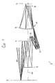
- a typical structure of an EUV projection lens 1 is shown by way of a preferred embodiment in FIG. It serves to image a pattern of a reticle or the like arranged in an object plane 2 in an image plane 3 oriented parallel to the object plane on a reduced scale, for example in the ratio 4: 1.
- the imaging takes place by means of electromagnetic radiation from the extreme ultraviolet range (EUV), in particular at a working wavelength of about 13.4 ⁇ m.
- EUV extreme ultraviolet range
- a total of six mirrors 4 to 9 provided with curved mirror surfaces and thus imaging are arranged coaxially with respect to one another, that they define a common optical axis 10 which is perpendicular to the image plane and the object plane.
- the mirror substrates 4 to 9 have the shape of rotationally symmetric aspheres whose symmetry axis coincides with the common mechanical axis 10.
- the light from an illumination system (not shown), which comprises a light source for soft X-ray radiation, initially strikes the reflective mask arranged in the object plane 2 from the image-facing side of the object plane 2.
- the reflected light impinges on a first mirror 4, which has an object-directed, concave mirror surface, which slightly narrows the impinging radiation onto a second mirror 5.
- the second mirror 5 has a concave mirror surface facing the first mirror 4, which reflects the radiation in the direction of a third mirror 6 as a convergent beam.
- the third mirror 6 has a convex mirror surface, which reflects the off-axis impinging radiation in the direction of a concave mirror surface of a fourth mirror 7.
- the latter is used in a mirror area far outside the optical axis and reflects the incident radiation to form a real intermediate image 11 on a fifth mirror 8 arranged in the vicinity of the image plane 3.
- This has a convex mirror surface facing away from the image plane, which reflects the incident divergent radiation reflected in the direction of a sixth mirror 9, which has a facing to the image plane 3, concave mirror surface with which the incident radiation is reflected and focused on the image plane 3.
- All reflective surfaces of the mirrors 4 to 9 are coated with reflection-enhancing reflective coatings.
- Preferred embodiments are layer stacks of, for example, about forty Alternating layer pairs, wherein a pair of alternating layers each comprise a silicon layer and a molybdenum layer.
- Table 1 summarizes the specification of the illustrated design in tabular form.
- Line 1 indicates the number or designation of the reflective or otherwise marked surfaces
- line 2 the radius of the surfaces (in millimeters)
- line 3 the distance of the respective surface to the following surface (in millimeters).
- the signs of the radii are chosen such that a positive sign corresponds to a curvature center of the mirror surface lying on the side of the image plane.
- Lines 4 to 9 labeled A to E indicate the aspheric coefficients of the aspheric mirror surfaces. It can be seen that all the mirror surfaces are aspherically curved.
- any layer design used may interfere with the passing wavefront only insofar as the overall system does not move out of a local minimum of its properties found in developing the basic design with uncoated substrates.
- wavefront errors of higher order hardly occur, the essential effects are distortion and defocusing.
- Quality criteria for such layer designs are, in addition to the wavefront (for example described by Zernike coefficients) and the distortion (in the scan direction corresponding to the y direction) and in the cross-scan direction (corresponding to the x direction) the field uniformity and the pupil apodization. Design and manufacturing system properties remain virtually unchanged compared to the basic design with uncoated substrates.
- a projection lens in which all reflective coatings have a constant layer thickness.
- an average value for the average angle of incidence on the respective mirror is expediently calculated from the angular load calculations for each mirror, for which purpose the average angle of incidence over the entire useful range of the mirror is averaged.
- an associated optimal layer thickness is then determined and a corresponding layer design is created in a manner known per se.
- the essential effect of the uniformly thick layers is a constant image offset in the scan direction with a clear defocusing. These first order errors can be achieved through re-optimization be corrected again.
- the wavefront aberration characterized by the rms value, resulted in a deterioration of about 20% compared to uncoated designs.
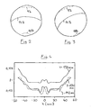
- FIG. 2 shows this distribution for a field point lying on the symmetry axis of the system
- FIG. 3 showing the distribution for a field point at the edge of the field Ringfeldes represents.
- the given percentages indicate fractions of the light intensity present at the entrance of the projection objective.
- the two intensity distributions only differ by a rotation about the axis of the exit pupil. The angle of rotation results from the position of the field point in the object or image plane.
- the schematic shows that a strong pupil apodization occurs.
- the intensity varies between about 3% and 14% across the pupil.
- the ranges of different values for the pupil intensity are shown by lines of equal intensity in FIGS. 2 and 3.
- the particular form of distribution with an out-of-exit pupil center would cause a large difference between the critical dimensions (CD's) for horizontal and vertical structures (hv difference).
- Fig. 4 shows schematically the transmission distribution across the field. While the variation in the scan direction (corresponding to the y values of the diagram) has no significant negative influence due to the integrating effect of the scanning process, the nonuniformity is perpendicular to the scan direction, ie in the cross-scan direction or x-direction , responsible for CD variations across the field.
- the near-field fifth mirror 8 is the mirror on which the largest variation of the mean angle of incidence occurs over the used mirror surface.
- the angle of incidence is the angle between the direction of incidence of the incoming radiation and the surface normal of the reflecting surface at the point of impact of the radiation.
- the incidence angle values in the example are between approx. 1 ° and 17 °. If this mirror is provided with layers of constant thickness, this leads to a relatively high loss of reflectivity.
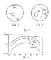
- a favorable compromise between high reflectivity and acceptable wavefront correction is possible in that at least this mirror 8 is covered with a graded, rotationally symmetrical reflection coating whose layer thickness profile according to equation (1) can be described.
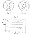
- FIGS. 5 and 6 of the intensity distributions in the exit pupil schematically show a high average transmission of, for example, 13.7%, whose fluctuation range is between approximately 12% and approximately 14%. is significantly lower than in the layer system of constant thickness described above.
- the field uniformity shown schematically in FIG. 7 is slightly worse at about 2.5% than at constant layer thicknesses.
- such layer systems with a lateral course are only suitable in exceptional cases because of a relatively strong distortion in the cross-scan direction (x-direction) because no compensation effect by the scanning process is effective for this distortion.
- this distortion in the cross-scan direction is based essentially on the decentration of the graded reflection layer of the fifth mirror 8. Accordingly, this effect can be reduced if the decentering is kept small or the graded reflection layer is arranged rotationally symmetric to the optical axis.
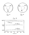
- Typical optical properties of a centered graded reflective layer design on the fifth mirror are shown in FIGS. 8-10. It can be seen that the pupil apodization is relatively large with about 8% in the area of the axis and about 14% in the edge of the pupil. However, it is rotationally symmetric to the pupil axis and thus independent of the field point. From this, the almost perfect uniformity ( ⁇ 0.4%) across the field, shown in FIG. 10, results directly. The total transmission is about 12% lower compared to the present design.
- FIGS. 11 to 13 is optimized with regard to rotationally symmetrical pupil apodization.
- centered, graded reflective coatings are applied to two mirrors, namely on the fifth mirror 8, on which the largest angle of incidence occurs, and on the third mirror 6 arranged in front of the light path.
- the centered layer courses of these mirrors are matched to one another the pupil apodization, similar to the embodiment of FIG. 8 to 10, is substantially rotationally symmetrical.
- the pupil apodization has a lower absolute value variation across the exit pupil, wherein the uniformity of the illumination is significantly better than with only one centered, graded reflective coating.
- the intensity variation in the exit pupil lies only between approximately 13.4% and approximately 15.6%, ie it is significantly lower than the corresponding variation in an embodiment with only one centered one Graded reflective coating ( Figures 8 to 10).
- the total transmission with approximately 14.7% compared to this embodiment is significantly larger and the field uniformity with values ⁇ 0.4% is almost perfect (FIG. 13).
- the rotationally symmetrical exit pupil is achieved by a specific coordination of the layer thickness profiles at the third and fifth mirror.
- the example shows that pupil homogeneity with a substantially rotationally symmetric profile can be achieved by means of a plurality of centered, graded reflective coatings whose layer thickness profiles are suitably matched to one another.
- FIGS. 14 to 16 A variant will now be described with reference to FIGS. 14 to 16, which enables an advantageous compromise between total transmission and field uniformity.
- it is preferably provided to decenter the layer profiles of a plurality, ie of at least two mirrors and to coordinate the individual decentrations so that the distortion contributions are partially or completely compensate.
- FIGS. 14 to 16 show the characteristics of a design in which, in addition to the fifth mirror 8, the third mirror 6 also has a decentered, graded reflective coating.
- the system exhibits a very high total transmission of approximately 13.6% and that shown in FIG. 16 schematically illustrated field uniformity is acceptable with about 1.6% static field uniformity.
- the value integrated by the scan movement should be in the range of 1% or less and thus be much cheaper. It can be seen in FIGS. 14 and 15 that a course of the intensity distribution in the pupil is produced by these coatings, which is somewhat less favorable than with a centered, graded coating (FIGS. 8 and 9).
- the fluctuation range is between approx. 9% and 14%.
- the apodization is not complete or rotationally symmetric, which may adversely affect telecentricity and process windows.
Description
Die Erfindung betrifft ein Projektionsobjektiv zur Abbildung eines in einer Objektebene angeordneten Musters in eine Bildebene mit Hilfe von elektromagnetischer Strahlung aus dem extremen Ultraviolettbereich (EUV).The invention relates to a projection objective for imaging a pattern arranged in an object plane into an image plane with the aid of electromagnetic radiation from the extreme ultraviolet region (EUV).
Projektionsobjektive dieser Art werden in Projektionsbelichtungsanlagen zur Herstellung von Halbleiterbauelementen und anderen feinstrukturierten Bauteilen verwendet. Sie dienen dazu, Muster von Photomasken oder Strichplatten, die nachfolgend allgemein als Masken oder Retikel bezeichnet werden, auf einen mit einer lichtempfindlichen Schicht beschichteten Gegenstand mit höchster Auflösung zu projizieren.Projection objectives of this type are used in projection exposure equipment for the production of semiconductor devices and other fine-structured components. They serve to project patterns of photomasks or reticles, hereafter commonly referred to as masks or reticles, onto a photosensitive layer-coated article with the highest resolution.
Um immer feinere Strukturen erzeugen zu können, werden verschiedene Wege verfolgt, das Auflösungsvermögen der Projektionsobjektive zu erhöhen. Bekanntlich kann das Auflösungsvermögen dadurch erhöht werden, dass die bildseitige numerische Apertur (NA) des Projektionsobjektives vergrößert wird. Eine andere Maßnahme ist es, mit immer kürzeren Wellenlängen der verwendeten elektromagnetische Strahlung zu arbeiten.In order to be able to produce ever finer structures, various ways are pursued to increase the resolution of the projection objectives. As is known, the resolution can be increased thereby be that the image-side numerical aperture (NA) of the projection lens is increased. Another measure is to work with shorter and shorter wavelengths of the electromagnetic radiation used.
Die Verbesserung der Auflösung durch Steigerung der numerischen Apertur hat einige Nachteile. Der größte Nachteil besteht darin, dass mit steigender numerischer Apertur die erzielbare Schärfentiefe (depth of focus, DOF) abnimmt. Dies ist nachteilig, weil beispielsweise aus Gründen der erzielbaren Ebenheit der zu strukturierenden Substrate und mechanischer Toleranzen eine Schärfentiefe in der Größenordnung von mindestens einem Mikrometer wünschenswert ist. Daher wurden Systeme entwickelt, die bei moderaten numerischen Aperturen arbeiten und die Vergrößerung des Auflösungsvermögens im wesentlichen durch die kurze Wellenlänge der verwendeten elektromagnetischen Strahlung aus dem extremen Ultraviolettbereich (EUV) erzielen. Bei der EUV-Lithographie mit Arbeitswellenlänge von 13,4nm kann beispielsweise bei numerischen Aperturen von NA=0,1 theoretisch eine Auflösung in der Größenordnung von 0,1µm bei typischen Schärfentiefen in der Größenordnung von ca. 1µm erreicht werden.The improvement of the resolution by increasing the numerical aperture has some disadvantages. The biggest disadvantage is that with increasing numerical aperture the achievable depth of field (DOF) decreases. This is disadvantageous because, for example, for reasons of achievable flatness of the substrates to be structured and mechanical tolerances, a depth of field of the order of at least one micrometer is desirable. Therefore, systems have been developed which operate at moderate numerical apertures and which achieve the increase in resolution essentially by the short wavelength of the extreme ultraviolet (EUV) electromagnetic radiation used. In the case of EUV lithography with a working wavelength of 13.4 nm, for example, numerical apertures of NA = 0.1 can theoretically achieve a resolution of the order of 0.1 μm at typical depths of field of the order of approximately 1 μm.
Strahlung aus dem extrem Ultraviolettbereich kann bekanntlich nicht mehr mit Hilfe refraktiver optischer Elemente fokussiert werden, da die kurzen Wellenlängen von den bekannten, bei höheren Wellenlängen transparenten optischen Materialien absorbiert werden. Daher werden für die EUV-Lithographie Spiegelsysteme eingesetzt, bei denen zwischen der Objektebene und der Bildebene mehrere mit Reflexbeschichtungen versehene, abbildende, d.h. konkave oder konvexe Spiegel angeordnet sind, die eine optische Achse des Projektionsobjektivs definieren. Die verwendeten Reflexbeschichtungen sind typischerweise Mehrlagenbeschichtungen, beispielsweise mit Molybdän/Silizium-Wechselschichten.Radiation from the extreme ultraviolet region can no longer be focused with the aid of refractive optical elements since the short wavelengths are absorbed by the known optical materials which are transparent at higher wavelengths. Therefore, for the EUV lithography mirror systems are used, in which between the object plane and the image plane a plurality of reflective coatings provided with imaging, ie concave or convex mirrors are arranged, which define an optical axis of the projection lens. The reflective coatings used are typically multilayer coatings, for example with molybdenum / silicon alternating layers.
Ein Spiegelobjektiv für die EUV-Lithographie mit vier Spiegeln, die jeweils Reflexbeschichtungen mit gleichmäßiger Schichtdicke aufweisen, ist in der US 5,973,826 offenbart.A mirror lens for EUV lithography with four mirrors, each having reflective coatings with uniform layer thickness, is disclosed in US 5,973,826.
Ein anderes EUV-Lithographiesystem ist in der US 5,153,898 gezeigt. Das System hat maximal fünf Spiegel, von denen mindestens eine eine asphärische Spiegelfläche aufweist. Es sind zahlreiche Materialkombinationen für EUV- geeignete Mehrlagen-Reflexbeschichtungen angegeben. Die Schichten haben jeweils gleichmäßige Schichtdicken.Another EUV lithography system is shown in US 5,153,898. The system has a maximum of five mirrors, at least one of which has an aspherical mirror surface. There are numerous combinations of materials for EUV-suitable multilayer reflective coatings. The layers each have uniform layer thicknesses.
Reflexbeschichtungen konstanter Dicke sind zwar relativ einfach herstellbar, erzeugen jedoch in der Regel bei Abbildungssystemen, bei denen der Einfallswinkel oder Inzidenzwinkel der verwendeten Strahlung auf die Spiegelfläche stark über den genutzten Spiegelbereich variiert, große Reflexionsverluste, da die Schichtdicke nur für einen speziell gewählten Einfallswinkel bzw. einen engen Einfallswinkelbereich optimal arbeitet. Ein weiterer Nachteil ist eine mangelhafte Pupillenhomogenität, die zu einem Telezentriefehler, strukturabhängiger oder feldabhängiger Auflösungsgrenze (sogenannte H-V-Differenzen oder CD-Variationen) und generell zu einer Verkleinerung des Prozessfensters führt.Reflective coatings of constant thickness are relatively easy to produce, but usually produce in imaging systems in which the angle of incidence or angle of incidence of the radiation used on the mirror surface varies greatly over the mirror range used, large reflection losses, since the layer thickness only for a specially selected angle of incidence or a narrow angle of incidence optimally works. A further disadvantage is a defective pupil homogeneity, which leads to a telecentricity error, structure-dependent or field-dependent resolution limit (so-called H-V differences or CD variations) and generally to a reduction of the process window.
Es sind auch abbildende EUV-Spiegelsysteme bekannt, bei denen Spiegel mit gradierten Reflexbeschichtungen vorgesehen sind, die sich dadurch auszeichnen, dass sie einen zur optischen Achse des Gesamtsystemes rotationssymmetrischen Schichtdickenverlauf aufweisen (US 5,911,858). Mit Hilfe gradierter Reflexbeschichtungen kann eine bessere Gleichverteilung der reflektierten Intensität über einen gewissen Inzidenzwinkelbereich erzielt werden.There are also known imaging EUV mirror systems in which mirrors are provided with graded reflective coatings, which are characterized in that they have a rotationally symmetrical to the optical axis of the overall system layer thickness profile (US 5,911,858). With graded reflective coatings, a better uniform distribution of the reflected intensity over a certain angle of incidence range can be achieved.
Photolithographiegeräte oder Stepper verwenden zwei unterschiedliche Methoden der Projektion einer Maske auf ein Substrat, nämlich das "Step-and-repeat" und das "Step-and-Scan"-Verfahren. Beim "Step-and-repeat"-Verfahren werden nacheinander größere Substratbereiche mit jeweils dem gesamten auf einem Retikel vorhandenen Muster belichtet. Entsprechende Projektionsoptiken haben daher ein Bildfeld, das groß genug ist, um die gesamte Maske auf das Substrat abzubilden. Nach jeder Belichtung wird das Substrat verfahren und der Belichtungsprozess wiederholt. Dagegen wird beim hier bevorzugten Step-and-Scan-Verfahren das Maskenmuster durch einen beweglichen Schlitz auf das Substrat gescannt, wobei sich Maske und Substrat synchron im Verhältnis des Abbildungsmaßstabes des Projektionsobjektives gegeneinander in der Scan-Richtung bewegen.Photolithography devices or steppers use two different methods of projection of a mask onto a substrate, namely the "Step-and-repeat" and the "step-and-scan" method. In the "step-and-repeat" method, larger substrate areas are exposed successively, each with the entire pattern present on a reticle. Corresponding projection optics therefore have an image field large enough to image the entire mask onto the substrate. After each exposure, the substrate is moved and the exposure process is repeated. In contrast, in the preferred step-and-scan method, the mask pattern is scanned by a movable slot on the substrate, wherein the mask and substrate move synchronously in relation to the magnification of the projection lens in the scan direction.
Der Erfindung liegt die Aufgabe zugrunde, ein mit hoher numerischer Apertur betreibbares EUV-Projektionsobjektiv bereitzustellen, das bei ausreichender Abbildungsqualität eine gute Korrektur von Verzeichnungsfehlern in allen Bildrichtungen und eine hinreichend symmetrische Ausleuchtung des Bildfeldes mit hoher Beleuchtungsintensität ermöglicht. Insbesondere soll ein Projektionsobjektiv geschaffen werden, welches unter optischen Gesichtspunkten einen sinnvollen Kompromiss zwischen Wellenfrontfehler, Verzeichnung, Gesamttransmission, Felduniformität und Pupillenhomogenität darstellt.The object of the invention is to provide an EUV projection objective which can be operated with a high numerical aperture and, with sufficient imaging quality, enables a good correction of distortion errors in all image directions and a sufficiently symmetrical illumination of the image field with high illumination intensity. In particular, a projection lens is to be created, which constitutes a sensible compromise between wavefront error, distortion, total transmission, field uniformity and pupil homogeneity from an optical point of view.
Diese Aufgabe wird gelöst durch ein Projektionsobjektiv gemäß Anspruch 1 zur Abbildung eines in einer Objektebene angeordneten Musters in eine Bildebene mit Hilfe von elektromagnetischer Strahlung aus dem extremen Ultraviolettbereich (EUV), wobei zwischen der Objektebene und der Bildebene mehrere mit Reflexbeschichtungen versehene, abbildende Spiegel angeordnet sind, die eine optische Achse des Projektionsobjektives definieren, wobei mindestens einer der Spiegel eine dezentrierte, gradierte Reflexbeschichtung mit einem zu einer Beschichtungsachse rotationssymmetrische Schichtdickenverlauf aufweist, bei der die Beschichtungsachse exzentrisch zur optischen Achse des Projektionsobjektives angeordnet ist.This object is achieved by a projection objective according to claim 1 for imaging a pattern arranged in an object plane into an image plane with the aid of electromagnetic radiation from the extreme ultraviolet region (EUV), wherein a plurality of reflecting mirrors are arranged between the object plane and the image plane , which define an optical axis of the projection objective, wherein at least one of the mirrors has a decentered, graded reflection coating with a layer thickness course which is rotationally symmetrical to a coating axis, in which case the coating axis is arranged eccentrically to the optical axis of the projection lens.
Die bei der Erfindung vorgesehene Dezentrierung einer gradierten, rotationssymmetrischen Reflexbeschichtung in Bezug auf die optische Achse des gesamten Abbildungssystemes schafft einen bei herkömmlichen Systemen nicht vorhandenen, zusätzlichen Freiheitsgrad für die Optimierung der optischen Eigenschaften des Projektionsobjektivs. Hierbei ist zu berücksichtigen, dass das Design bzw. die optische Auslegung eines EUV-Projektionssystemes sich grob in zwei aufeinanderfolgende Schritte unterteilen lässt. Zunächst werden die Anordnung und die Gestaltung der unbeschichteten Spiegelsubstrate unter Berücksichtigung der klassischen Kriterien (z.B. Wellenfrontaberrationen, Verzeichnung, Baubedingungen, Fertigungsbedingungen etc.) rechnerisch mit Hilfe geeigneter Design-Software optimiert. Anschließend werden die Reflexbeschichtungen berechnet und das Design wird unter Berücksichtigung der Reflexbeschichtungen neu durchgerechnet. Die Schichten werden sozusagen auf die unbeschichteten Substrate "gelegt". Hierdurch ergibt sich im allgemeinen eine deutliche Verschlechterung der vom unbeschichteten System erreichten Abbildungsqualität, die in der Regel nicht ohne eine anschließende Reoptimierung des Systems toleriert werden kann.The decentering of a graded, rotationally symmetrical reflective coating with respect to the optical axis of the entire imaging system provided in the invention provides an additional degree of freedom not available in conventional systems for optimizing the optical properties of the projection objective. It should be noted that the design or optical design of an EUV projection system can be roughly divided into two consecutive steps. First, the layout and design of the uncoated mirror substrates are computationally optimized using appropriate design software, taking into account the classical criteria (e.g., wavefront aberrations, distortion, build conditions, manufacturing conditions, etc.). Subsequently, the reflective coatings are calculated and the design is recalculated taking into account the reflective coatings. The layers are "laid" on the uncoated substrates, so to speak. This generally results in a significant deterioration of the imaging quality achieved by the uncoated system, which generally can not be tolerated without subsequent re-optimization of the system.
Bei der Reoptimierung sind unter anderem die durch die Reflexbeschichtungen hervorgerufenen Wellenfrontaberrationen und Wellenfrontapodisierungen zu berücksichtigen. Konkurrierende Effekte sind dabei vor allem die Gesamttransmission des Systems einerseits und die Felduniformität andererseits. Es wurde herausgefunden, dass diese wichtigen Eigenschaften in der Regel durch die zur Verfügung stehenden Änderungsmöglichkeiten am Design gegenläufig beeinflusst werden. Gute Kompromisslösungen, die hinreichende Gesamttransmission bei ausreichender Felduniformität liefern, können mit Hilfe dezentrierter, rotationssymmetrischer Reflexbeschichtungen besonders günstig erreicht werden. Dabei hat sich allgemein gezeigt, dass die Bereitstellung von dezentrierten, gradierten Reflexbeschichtungen besonders für die Gesamttransmission förderlich ist. Die Felduniformität bevorzugt dagegen Reflexbeschichtungen, die zur optischen Achse zentriert sind.In the re-optimization, inter alia, the wavefront aberrations and wavefront apodizations caused by the reflective coatings must be taken into account. Competing effects are above all the overall transmission of the system on the one hand and the field uniformity on the other hand. It has been found that these important properties are usually counteracted by the available design choices. Good compromise solutions that provide sufficient overall transmission with sufficient field uniformity can be achieved particularly favorably with the aid of decentred, rotationally symmetrical reflective coatings. It has generally been shown that the provision of decentred, graded reflective coatings is particularly conducive to overall transmission. In contrast, field uniformity prefers reflective coatings centered on the optical axis.
Als Ausgangspunkt für die Reoptimierung dienen in der Regel Winkelbelastungsrechnungen für die einzelnen Spiegelflächen. Aus diesen können insbesondere die tatsächlich genutzten Bereiche (foot prints) eines jeden Spiegels, die durchschnittlichen Einfallswinkel in jedem Punkt jedes Spiegels und die Winkelbandbreiten bzw. Inzidenzwinkelbereiche in jedem Punkt eines Spiegels abgeleitet werden. Von diesen Daten sind besonders die durchschnittlichen Einfallswinkel und der Inzidenzwinkelbereich (Winkelbandbreite) von Bedeutung.The starting point for the re-optimization is usually angle load calculations for the individual mirror surfaces. From these, in particular, the actual footprints of each mirror, the average angles of incidence at each point of each mirror, and the angular bandwidths or angles of incidence at each point of a mirror can be deduced. Of these data, the average incident angle and the angle of incidence range (angle bandwidth) are particularly important.
Da Beschichtungen für die EUV-Systeme in erster Linie dazu dienen sollen, die auftreffende elektromagnetische Strahlung so stark wie möglich zu reflektieren, kann das Design in Richtung maximaler Reflektivität optimiert werden. Hierzu können die aus Winkelbelastungsberechnungen erhältlichen mittleren Einfallswinkel für jeden Punkt herangezogen und zur Grundlage der Berechnung der für die Reflektivität optimalen Schichtdicken herangezogen werden. Der Verlauf wird wesentlich durch die Form des Objektfeldes mitbestimmt, das bei bevorzugten Ausführungsformen ein Ringfeldsegment ist.Since coatings for the EUV systems are primarily intended to reflect the impinging electromagnetic radiation as much as possible, the design can be optimized in the direction of maximum reflectivity. For this purpose, the average angle of incidence obtainable from angular load calculations can be used for each point and used as the basis for calculating the optimum layer thicknesses for the reflectivity. The course is significantly influenced by the shape of the object field, which in preferred embodiments is a ring field segment.
Es hat sich gezeigt, dass es vorteilhaft ist, wenn zumindest der Spiegel mit dem größten Inzidenzwinkelbereich, d.h. der größten Winkelbandbreite, eine dezentrierte, gradierte Reflexbeschichtung aufweist. Dem liegt die Erkenntnis zugrunde, dass konstante Schichtdicken bei Systemen, bei denen der Einfallswinkel stark über den Spiegelbereich variiert, einen enormen Verlust an Reflexionsgrad bringen, da Schichten konstanter Dicke nur für einen speziell gewählten Einfallswinkel bzw. einen engen Einfallswinkelbereich optimiert werden können. Dieses Problem tritt insbesondere bei hochaperturigen Systemen (z.B. bei Systemen mit NA >0,2) auf, da die Einfallswinkel auf den Spiegeln maßgeblich durch die Apertur bestimmt sind. Wird derjenige Spiegel identifiziert, bei dem der größte Inzidenzwinkelbereich auftritt, so können durch Designmaßnahmen, wie eine Dezentrierung einer rotationssymmetrischen Reflexbeschichtung, besonders wirksame Eingriffe in die Abbildungseigenschaften des Systems vorgenommen werden.It has been shown that it is advantageous if at least the mirror with the largest incidence angle range, ie the largest angular bandwidth, has a decentered, graded reflective coating. This is based on the finding that constant layer thicknesses in systems in which the angle of incidence varies greatly over the mirror range, bring a tremendous loss of reflectivity, since layers of constant thickness can be optimized only for a specially chosen angle of incidence or a narrow range of angles of incidence. This problem occurs especially in high-aperture systems (eg in systems with NA> 0.2), since the angles of incidence on the mirrors are largely determined by the aperture. If the mirror is identified in which the largest angle of incidence range occurs, design measures, such as decentration of a rotationally symmetrical reflective coating, can be used to make particularly effective interventions in the imaging properties of the system.
Bei einer bevorzugten Ausführungsform reicht der Inzidenzwinkelbereich des Spiegels mit größtem Inzidenzwinkelbereich bis zu Winkeln unterhalb von 5 bis 10° und oberhalb von 10 oder 15°. Der Inzidenzwinkelbereich kann beispielsweise von ca. 1° bis ca. 17° reichen.In a preferred embodiment, the angle of incidence range of the mirror ranges from the widest angle of incidence to angles below 5 to 10 degrees and above 10 or 15 degrees. The range of incidence ranges, for example, from about 1 ° to about 17 °.
Wenn ein Spiegelsystem auf besonders hohe Gesamttransmissionen optimiert werden soll und gegebenenfalls die Felduniformität eine untergeordnete Rolle spielt, so kann es vorteilhaft sein, wenn zumindest der Spiegel mit dem größten Inzidenzwinkelbereich eine dezentrierte, gradierte Reflexbeschichtung aufweist. Deren Schichtdickenverlauf in Radialrichtung kann so optimiert werden, dass sich im gesamten Inzidenzwinkelbereich ein hoher Reflexionsgrad für die verwendete Strahlung einstellt. Allerdings kann es bei einer komplexen Optimierungsaufgabe so sein, dass die Verwendung von reflexoptimierten Schichten das System so weit von einem ursprünglich erreichten lokalen Minimum der Optimierung entfernt, das eine automatische Auffindung dieses Minimums nicht mehr möglich ist. Dadurch besteht die Gefahr, dass statt einer Reoptimierung eines Designs ein demgegenüber neues Design entsteht.If a mirror system is to be optimized for particularly high total transmissions and, if appropriate, the field uniformity plays a subordinate role, then it may be advantageous if at least the mirror with the largest incidence angle range has a decentered, graded reflective coating. Their layer thickness profile in the radial direction can be optimized so that a high degree of reflection for the radiation used is achieved over the entire range of angles of incidence. However, in a complex optimization task, using a reflex-optimized layer may remove the system so far from an originally achieved local minimum of optimization that an automatic discovery of that minimum is no longer possible. As a result, there is a risk that instead of re-optimizing a design, a new design is created.
Da eine einzige dezentrierte, gradierte Reflexbeschichtung innerhalb eines Spiegelsystems neben den erwünschten positiven Wirkungen gegebenenfalls auch negative Einflüsse auf die Abbildungsqualität haben kann, ist in bevorzugten Ausführungsformen ein Spiegel mit einer ersten dezentrierten gradierten Reflexbeschichtung und mindestens ein anderer Spiegel mit einer zweiten, dezentrierten gradierten Reflexbeschichtung vorgesehen, wobei die erste und die zweite dezentrierte gradierte Reflexbeschichtung derart in Bezug auf Dezentrierung, Schichtdickenverlauf etc. aufeinander abgestimmt sind, dass sich Beiträge der Reflexbeschichtungen zu bestimmten Bildfehlern mindestens teilweise kompensieren. Hier ist insbesondere die Verzeichnung in Cross-Scan-Richtung (x-Richtung) kritisch, da für diese Art der Verzeichnung kein Kompensationseffekt durch den in der senkrecht dazu verlaufenden y-Richtung verlaufenden Scanvorgang existiert. Bei bevorzugten Ausführungsformen ist die Dezentrierung der Reflexbeschichtung daher so gestaltet, dass die Beschichtungsachse relativ zur optischen Achse des Projektionsobjektives in einer y-Richtung dezentriert ist, welche bei einem Scanner der Scanrichtung entspricht.Since a single decentered, graded reflective coating within a mirror system may, in addition to the desired positive effects, possibly also have negative effects on the imaging quality, in preferred embodiments, a mirror with a first decentered graded reflective coating and at least one other mirror provided with a second, decentered graded reflective coating, wherein the first and the second decentered graded reflective coating are so matched to each other in terms of decentration, Schichtdickenverlauf, etc. that reflect contributions of the reflective coatings to certain artifacts at least partially , Here, in particular, the distortion in the cross-scan direction (x-direction) is critical, since for this type of distortion there is no compensation effect due to the scanning process running in the perpendicular y-direction. In preferred embodiments, the decentering of the reflective coating is therefore designed so that the coating axis is decentered relative to the optical axis of the projection objective in a y-direction, which corresponds to the scan direction in a scanner.
Es hat sich als vorteilhaft herausgestellt, wenn die Schichtdicke d des rotationssymmetrischen Schichtdickenverlaufes folgender Form entspricht: 
genügt. Dabei bezeichnet d0 die für senkrechten Strahlungseinfall (Inzidenzwinkel = 00) optimierte Schichtdicke, r0 beschreibt die Dezentrierung der Beschichtungsachse in der x-y-Ebene gegenüber der optischen Achse des Systems und r beschreibt die aktuelle Koordinate in der x-y-Ebene. Die Parameter c sind Polynomenkoeffizienten. Der bevorzugte Schichtdickenverlauf ist also durch ein quadratisches Polynom ohne ungerade, insbesondere ohne lineare Terme beschreibbar und kann in einem einfachen Fall beispielsweise parabelförmig sein.It has proven to be advantageous if the layer thickness d of the rotationally symmetrical layer thickness profile corresponds to the following form:
enough. D 0 denotes the layer thickness optimized for vertical incidence of radiation (angle of incidence = 0 ° ), r 0 describes the decentring of the coating axis in the xy plane with respect to the optical axis of the system and r describes the current coordinate in the xy plane. The parameters c are polynomial coefficients. The preferred layer thickness profile can thus be described by a quadratic polynomial without odd, in particular without linear terms, and in a simple case can be parabolic, for example.
Ein im Zusammenhang mit einem Ausführungsbeispiel näher erläutertes, bevorzugtes Projektionsobjektiv hat zwischen Objektebene und Bildebene sechs Spiegel. Der fünfte, auf die Objektebene folgende Spiegel ist derjenige Spiegel, bei dem der größte Inzidenzwinkelbereich auftritt. Dieser Spiegel kann bei einem reflexoptimierten System eine zentrierte, gradierte Reflexionsschicht haben. Bei anderen Varianten sind bei mehreren Spiegeln zentrierte, gradierte Reflexbeschichtungen vorgesehen, die so aufeinander abgestimmt sind, dass die Pupillenhomogenität im wesentlichen rotationssymmetrisch ist. Bevorzugt sind zwei, maximal vier solcher Spiegel, da laterale Schichtdickenverläufe fertigungstechnisch aufwendig sind. Für eine gleichzeitige Optimierung mehrerer Qualitativkriterien, insbesondere der Gesamttransmission und der Verzeichnung, ist zumindest an diesem fünften Spiegel eine dezentrierte, gradierte Reflexionsschicht vorgesehen.A preferred projection lens, which is explained in more detail in connection with one exemplary embodiment, has six mirrors between the object plane and the image plane. The fifth mirror following the object plane is the mirror with the largest incidence angle range. This mirror can have a centered, graded reflection layer in a reflex-optimized system. In other variants centered, graded reflective coatings are provided with multiple mirrors, which are coordinated so that the pupil homogeneity is substantially rotationally symmetrical. Preferably, two, at most four such mirrors, since lateral Schichtdickenverläufe are expensive manufacturing technology. For a simultaneous optimization of several qualitative criteria, in particular the total transmission and the distortion, a decentred, graded reflection layer is provided at least at this fifth mirror.
Besonders günstige Ergebnisse werden erzielt, wenn mindestens einer der dem fünften Spiegel vorgeschalteten Spiegel, beispielsweise der dritte oder der vierte Spiegel, ebenfalls eine dezentrierte, gradierte Reflexbeschichtung aufweist, wobei die Rotationsachsen der beiden Schichtverläufe der aufeinanderfolgenden, gradierten Reflexionsschichten parallel zur optischen Achse derart dezentriert werden, dass sich die jeweiligen Beiträge zur Verzeichnung in Cross-Scan-Richtung gegenseitig wenigstens teilweise gegenseitig kompensieren.Particularly favorable results are achieved if at least one of the mirrors preceding the fifth mirror, for example the third or the fourth mirror, likewise has a decentered, graded reflective coating, the axes of rotation of the two layer courses of the successive, graded reflection layers being decentered parallel to the optical axis in that the respective contributions to the distortion in the cross-scan direction mutually compensate each other at least partially.
Die vorstehenden und weitere Merkmale gehen außer aus den Ansprüchen auch aus der Beschreibung und den Zeichnungen hervor, wobei die einzelnen Merkmale jeweils für sich allein oder zu mehreren in Form von Unterkombinationen bei einer Ausführungsform der Erfindung und auf anderen Gebieten verwirklicht sein und vorteilhafte sowie für sich schutzfähige Ausführungen darstellen können. Es zeigen:
- Fig. 1
- eine schematische Längsschnittdarstellung einer Ausführungsform eines EUV-Projektionsobjektivs mit sechs abbildenden Spiegeln,
- Fig. 2
- eine schematische Darstellung einer Transmissionsverteilung in der Austrittspupille des Projektionsobjektivs für einen Feldpunkt auf der Symmetrieachse bei Verwendung von Reflexschichten mit konstanter Schichtdicke auf allen Spiegeln,
- Fig. 3
- eine entsprechende Transmissionsverteilung in der Austrittspupille für einen Feldpunkt am Rande des Ringfeldes;
- Fig. 4
- ein schematische Diagramm der Transmissionsverteilung über das Bildfeld bei Verwendung von Reflexbeschichtungen mit konstanter Schichtdicke,
- Fig. 5
- eine schematische Darstellung einer Transmissionsverteilung in der Austrittspupille für einen Feldpunkt auf der Symmetrieachse bei einem Projektionsobjektiv, welches auf einem Spiegel eine dezentrierte, gradierte Reflexbeschichtung aufweist,
- Fig. 6
- eine entsprechende Transmissionsverteilung in der Austrittspupille für einen Feldpunkt am Rande des Ringfeldes,
- Fig. 7
- ein schematisches Diagramm einer Transmissionsverteilung über das Bildfeld bei Verwendung einer dezentrierten, gradierten Reflexbeschichtung,
- Fig. 8
- eine schematische Darstellung der Transmissionsverteilung in der Austrittspupille für einen Feldpunkt auf der Symmetrieachse bei einem Projektionsobjektiv mit einer zentrierten, gradierten Reflexbeschichtung auf einem der Spiegel,
- Fig. 9
- eine entsprechende Transmissionsverteilung in der Austrittspupille für einen Feldpunkt am Rande des Ringfeldes,
- Fig. 10
- ein schematisches Diagramm einer Transmissionsverteilung
- Fig. 11
- über das Bildfeld bei einem Projektionsobjektiv mit einer zentrierten, gradierten Reflexionsbeschichtung auf einem der Spiegel, eine schematische Darstellung der Transmissionsverteilung in
- Fig. 12
- der Austrittspupille für einen Feldpunkt auf der Symmetrieachse bei einem Projektionsobjektiv, bei welchen auf zwei Spiegeln zentrierte, gradierte Reflexbeschichtungen vorgesehen sind, die zur Erzielung einer im wesentlichen rotationssymmetrischen Pupillenhomogenität auf einander abgestimmt sind, eine entsprechende Transmissionsverteilung in der
- Fig. 13
- Austrittspupille für einen Feldpunkt am Rande des Ringfeldes, ein schematisches Diagramm einer Transmissionsverteilung
- Fig. 14
- über das Bildfeld bei einem Projektionsobjektiv mit zentrierten, gradierten Reflexionsbeschichtungen auf zwei Spiegeln, ein schematisches Diagramm einer Transmissionsverteilung in der Austrittspupille für einen Feldpunkt auf der Symmetrieachse bei einem Projektionsobjektiv, bei dem an zwei Spiegeln jeweils eine dezentrierte, gradierte Reflexbeschichtung angebracht ist, wobei die Dezentrierung der Reflexbeschichtungen zur gegenseitigen Kompensation von Verzeichnungsbeiträgen aneinander angepasst sind,
- Fig. 15
- eine entsprechende Transmissionsverteilung in der Austrittspupille für einen Feldpunkt am Rande des Ringfeldes, und
- Fig. 16
- ein schematisches Diagramm einer Transmissionsverteilung über das Bildfeld für ein Projektionsobjektiv, bei dem an zwei Spiegeln dezentrierte, gradierte Reflektionsbeschichtungen zur gegenseitigen Kompensation und von Verzeichnungsbeiträgen angeordnet sind.
- Fig. 1
- FIG. 2 is a schematic longitudinal sectional view of an embodiment of an EUV projection objective with six imaging mirrors. FIG.
- Fig. 2
- a schematic representation of a transmission distribution in the exit pupil of the projection lens for a field point on the axis of symmetry when using reflective layers with constant thickness on all mirrors,
- Fig. 3
- a corresponding transmission distribution in the exit pupil for a field point at the edge of the ring field;
- Fig. 4
- a schematic diagram of the transmission distribution over the image field when using reflective coatings with a constant layer thickness,
- Fig. 5
- a schematic representation of a transmission distribution in the exit pupil for a field point on the axis of symmetry in a projection lens, which has a decentered, graded reflective coating on a mirror,
- Fig. 6
- a corresponding transmission distribution in the exit pupil for a field point at the edge of the ring field,
- Fig. 7
- a schematic diagram of a transmission distribution over the image field when using a decentered, graded reflective coating,
- Fig. 8
- a schematic representation of the transmission distribution in the exit pupil for a field point on the axis of symmetry in a projection lens with a centered, graded reflective coating on one of the mirrors,
- Fig. 9
- a corresponding transmission distribution in the exit pupil for a field point at the edge of the ring field,
- Fig. 10
- a schematic diagram of a transmission distribution
- Fig. 11
- on the image field in a projection lens with a centered, graded reflection coating on one of the mirrors, a schematic representation of the transmission distribution in
- Fig. 12
- the exit pupil for a field point on the axis of symmetry in a projection lens, in which on two mirrors centered, graded reflective coatings are provided, which are tuned to achieve a substantially rotationally symmetric pupil homogeneity on each other, a corresponding transmission distribution in the
- Fig. 13
- Exit pupil for a field point at the edge of the ring field, a schematic diagram of a transmission distribution
- Fig. 14
- on the image field in a projection lens with centered, graded reflection coatings on two mirrors, a schematic diagram of a transmission distribution in the exit pupil for a field point on the axis of symmetry in a projection lens, in each case a decentered, graded reflective coating is attached to two mirrors, wherein the decentering the reflective coatings are matched to each other for mutual compensation of distortion contributions,
- Fig. 15
- a corresponding transmission distribution in the exit pupil for a field point at the edge of the ring field, and
- Fig. 16
- a schematic diagram of a transmission distribution over the image field for a projection lens, in which two mirrors decentered, graded reflection coatings for mutual compensation and distortion contributions are arranged.
Bei der folgenden Beschreibung wesentlicher der Erfindung Zugrundeliegender Prinzipien bezeichnet der Begriff "optischer Achse" eine gerade Linie oder eine Folge von geraden Linienabschnitten durch die paraxialen Krümmungsmittelpunkte der optischen Komponenten, bei denen es sich bei den beschriebenen Ausführungsformen ausschließlich um Spiegel mit gekrümmten Spiegelflächen handelt. Das Objekt ist in den Beispielen eine Maske (Retikel) mit dem Muster einer integrierten Schaltung, es kann sich aber auch um ein anderes Muster, beispielsweise eines Gitters, handeln. Das Bild wird in den Beispielen auf einem als Substrat dienenden, mit einer Photoresistschicht versehenen Wafer gebildet, jedoch sind auch andere Substrate, beispielsweise Elemente für Flüssigkeitskristallanzeigen oder Substrate für optische Gitter möglich.In the following description of essential principles of the invention, the term "optical axis" designates a straight line or a series of straight line sections through the paraxial centers of curvature of the optical components, which in the embodiments described are exclusively mirrors with curved mirror surfaces. The object in the examples is a mask (reticle) with the pattern of an integrated circuit, but it can also be a different pattern, for example a grid. The image is formed in the examples on a substrate provided with a photoresist layer wafer, but other substrates, for example, elements for liquid crystal displays or substrates for optical gratings are possible.
Ein typischer Aufbau eines EUV-Projektionsobjektivs 1 ist anhand eines bevorzugten Ausführungsbeispiels in Fig. 1 gezeigt. Es dient dazu, ein in einer Objektebene 2 angeordnetes Muster eines Retikels oder dergleichen in eine parallel zu Objektebene ausgerichtete Bildebene 3 in reduziertem Maßstab abzubilden, beispielsweise im Verhältnis 4:1. Die Abbildung erfolgt mittels elektromagnetischer Strahlung aus dem extremen Ultraviolettbereich (EUV), insbesondere bei einer Arbeitswellenlänge von ca. 13,4µm. Zwischen der Objektebene 2 und der Bildebene 3 sind insgesamt sechs mit gekrümmten Spiegelflächen versehene und dadurch abbildende Spiegel 4 bis 9 derart koaxial zueinander angeordnet, dass sie eine gemeinsame optische Achse 10 definieren, die senkrecht auf der Bildebene und der Objektebene steht. Die Spiegelsubstrate 4 bis 9 haben die Form rotationssymmetrischer Asphären, deren Symmetrieachse mit der gemeinsamen mechanischen Achse 10 zusammenfällt. Das für einen Step-and-Scan-Betrieb konzipierte Sechs-Spiegel-System arbeitet mit einem Off-Axis-Ringfeld, erreicht eine numerische Apertur NA=0,25 bei einer typischen Feldgröße von 2 x 26mm2.A typical structure of an EUV projection lens 1 is shown by way of a preferred embodiment in FIG. It serves to image a pattern of a reticle or the like arranged in an
Wie in Fig. 1 erkennbar, trifft das Licht aus einem (nicht gezeigten) Beleuchtungssystem, welches eine Lichtquelle für weiche Röntgenstrahlung umfasst, von der bildzugewandten Seite der Objektebene 2 zunächst die in der Objektebene 2 angeordnete reflektive Maske. Das reflektierte Licht trifft auf einen ersten Spiegel 4, der eine objektwärts gerichtete, konkave Spiegelfläche hat, welche die auftreffende Strahlung leicht verengt auf einen zweiten Spiegel 5 reflektiert. Der zweite Spiegel 5 hat eine dem ersten Spiegel 4 zugewandte konkave Spiegelfläche, die die Strahlung in Richtung eines dritten Spiegels 6 als konvergentes Strahlbündel reflektiert. Der dritte Spiegel 6 hat eine konvexe Spiegelfläche, die die außeraxial auftreffende Strahlung in Richtung einer konkaven Spiegelfläche eines vierten Spiegels 7 reflektiert. Dieser wird in einem Spiegelbereich weit außerhalb der optischen Achse genutzt und reflektiert die auftreffende Strahlung unter Bildung eines reellen Zwischenbildes 11 auf einen in der Nähe der Bildebene 3 angeordneten fünften Spiegel 8. Dieser hat eine von der Bildebene abgewandte konvexe Spiegelfläche, welche die auftreffende divergente Strahlung in Richtung eines sechsten Spiegels 9 reflektiert, welcher eine zur Bildebene 3 gewandte, konkave Spiegelfläche aufweist, mit der die auftreffende Strahlung reflektiert und auf die Bildebene 3 fokussiert wird.As can be seen in FIG. 1, the light from an illumination system (not shown), which comprises a light source for soft X-ray radiation, initially strikes the reflective mask arranged in the
Alle reflektierenden Flächen der Spiegel 4 bis 9 sind mit reflexionserhöhenden Reflexbeschichtungen belegt. Bei bevorzugten Ausführungsformen handelt es sich um Schichtstapel von beispielsweise ca. vierzig Wechselschichtpaaren, wobei ein Wechselschichtpaar jeweils eine Siliziumschicht und eine Molybdänschicht umfasst.All reflective surfaces of the
In Tabelle 1 ist die Spezifikation des dargestellten Design in tabellarischer Form zusammengefasst. Dabei gibt Zeile 1 die Nummer bzw. die Bezeichnung der reflektierenden oder auf andere Weise ausgezeichneten Flächen, Zeile 2 den Radius der Flächen (in Millimeter) und Zeile 3 den Abstand der jeweiligen Fläche zur nachfolgenden Fläche (in Millimeter) an. Die Vorzeichen der Radien sind so gewählt, dass ein positives Vorzeichen einem auf der Seite der Bildebene liegenden Krümmungsmittelpunkt der Spiegelfläche entspricht. Die mit A bis E bezeichneten Zeilen 4 bis 9 geben die Asphärenkoeffizienten der asphärischen Spiegelflächen an. Es ist erkennbar, dass sämtliche Spiegelflächen asphärisch gekrümmt sind. Die asphärischen Flächen können nach folgender Vorschrift berechnet werden: ![]()
![]()
Dabei gibt der Kehrwert (1/r) des Radius die Flächenkrümmung und h den Abstand eines Flächenpunktes von der optischen Achse an. Somit gibt p(h) diese Pfeilhöhe, d. h. den Abstand des Flächenpunktes vom Flächenscheitel in z-Richtung, d. h. in Richtung der optischen Achse. Die Konstanten K, A, B ... sind in Tabelle 1 wiedergegeben.The reciprocal (1 / r) of the radius indicates the surface curvature and h the distance of a surface point from the optical axis. Thus, p (h) gives this arrow height, i. H. the distance of the surface point from the surface apex in the z-direction, d. H. in the direction of the optical axis. The constants K, A, B ... are shown in Table 1.
Die in den nachfolgenden Zeilen dargestellten Koeffizienten C0, C2, xde und yde beschreiben den Schichtdickenverlauf der bei einer bevorzugten Ausführungsform auf den jeweiligen Spiegeln aufgebrachten Reflexbeschichtungen gemäß der Formel in Gleichung (1), die bereits oben erläutert wurde. Hierbei gilt: ![]()
![]()
Der Einfluss der gewählten Reflexbeschichtungen auf die Abbildungsqualität des Projektionsobjektives wird nun in verschiedenen Stufen erläutert.The influence of the selected reflective coatings on the imaging quality of the projection lens will now be explained in different stages.
Die rechnerische Konstruktion der Reflexbeschichtungen wurde unter der Randbedingung durchgeführt, dass jedes verwendete Schichtdesign die durchtretende Wellenfront nur insoweit stören darf, dass sich das Gesamtsystem nicht aus einem lokalen Minimum seiner Eigenschaften herausbewegt, welches bei Entwicklung des Grunddesigns mit unbeschichteten Substraten aufgefunden wurde. Dabei treten Wellenfrontfehler höherer Ordnung kaum auf, die wesentlichen Effekte sind Verzeichnung und Defokussierung. Qualitätskriterien für solche Schichtdesigns sind neben der Wellenfront (beispielsweise beschrieben durch Zernikekoeffizienten) und der Verzeichnung (in Scan-Richtung entsprechend y-Richtung) und in Cross-Scan-Richtung (entsprechend x-Richtung) die Felduniformität und die Pupillenapodisierung. Konstruktionstechnische und fertigungstechnische Systemeigenschaften bleiben gegenüber dem Grunddesign mit unbeschichteten Substraten nahezu unverändert.The computational construction of the reflective coatings was carried out under the condition that any layer design used may interfere with the passing wavefront only insofar as the overall system does not move out of a local minimum of its properties found in developing the basic design with uncoated substrates. In this case, wavefront errors of higher order hardly occur, the essential effects are distortion and defocusing. Quality criteria for such layer designs are, in addition to the wavefront (for example described by Zernike coefficients) and the distortion (in the scan direction corresponding to the y direction) and in the cross-scan direction (corresponding to the x direction) the field uniformity and the pupil apodization. Design and manufacturing system properties remain virtually unchanged compared to the basic design with uncoated substrates.
Zunächst wird ein Projektionsobjektiv erläutert, bei dem alle Reflexbeschichtungen eine konstante Schichtdicke haben. Hierzu wird zweckmäßig aus den Winkelbelastungsberechnungen für jeden Spiegel ein Mittelwert für die mittleren Einfallswinkel auf den jeweiligen Spiegel berechnet, wozu der mittlere Einfallswinkel über den gesamten Nutzbereich des Spiegels gemittelt wird. Auf Grundlage dieses globalen, mittleren Einfallswinkels wird dann eine zugehörige optimale Schichtdicke bestimmt und in an sich bekannter Weise ein entsprechendes Schichtdesign erstellt.First, a projection lens is explained in which all reflective coatings have a constant layer thickness. For this purpose, an average value for the average angle of incidence on the respective mirror is expediently calculated from the angular load calculations for each mirror, for which purpose the average angle of incidence over the entire useful range of the mirror is averaged. On the basis of this global average angle of incidence, an associated optimal layer thickness is then determined and a corresponding layer design is created in a manner known per se.
Der wesentliche Effekt der gleichförmig dicken Schichten besteht in einem konstanten Bildversatz in Scan-Richtung bei einer deutlichen Defukussierung. Diese Fehler erster Ordnung können durch Reoptimierung wieder korrigiert werden. Bei der Wellenfrontaberration, gekennzeichnet durch den rms-Wert, ergab sich gegenüber unbeschichteten Designs eine Verschlechterung um ca. 20%.The essential effect of the uniformly thick layers is a constant image offset in the scan direction with a clear defocusing. These first order errors can be achieved through re-optimization be corrected again. The wavefront aberration, characterized by the rms value, resulted in a deterioration of about 20% compared to uncoated designs.
In den Fig. 2 und 3 sind die Intensitätsverteilungen in der kreisrunden Austrittspupille des Projektionsobjektiv für zwei Feldpunkte schematisch dargestellt, wobei Fig. 2 diese Verteilung für einen auf der Symmetrieachse des Systems liegende Feldpunkt zeigt und Fig. 3 die Verteilung für einen Feldpunkt am Rande des Ringfeldes darstellt. Die angegebenen Prozentangaben bezeichnen Bruchteile der am Eintritt des Projektionsobjektives vorliegenden Lichtintensität. Entsprechend der Rotationssymmetrie des Systems und der Beschichtungen (diese sind aufgrund konstanter Schichtdicke um jede zur optischen Achse parallele Achse rotationssymmetrisch) unterscheiden sich die beiden Intensitätsverteilungen nur durch eine Drehung um die Achse der Austrittspupille. Der Drehwinkel ergibt sich aus der Lage des Feldpunktes in der Objekt- oder Bildebene.2 and 3, the intensity distributions in the circular exit pupil of the projection objective for two field points are shown schematically, FIG. 2 showing this distribution for a field point lying on the symmetry axis of the system, and FIG. 3 showing the distribution for a field point at the edge of the field Ringfeldes represents. The given percentages indicate fractions of the light intensity present at the entrance of the projection objective. Corresponding to the rotational symmetry of the system and the coatings (these are rotationally symmetric about each axis parallel to the optical axis due to the constant layer thickness), the two intensity distributions only differ by a rotation about the axis of the exit pupil. The angle of rotation results from the position of the field point in the object or image plane.
Die schematische Darstellung zeigt, dass eine starke Pupillenapodisierung auftritt. Die Intensität variiert zwischen ca. 3% und 14% über die Pupille. Die Bereiche verschiedener Werte für die Pupillenintensität sind anhand Linien gleicher Intensität in Fig. 2 und 3 dargestellt. Die spezielle Form der Verteilung mit einem außerhalb der Austrittspupille liegenden Zentrum würde eine große Differenz zwischen den kritischen Dimensionen (CD-Werten) für horizontale und vertikale Strukturen (h-v-Differenz) hervorrufen. Fig. 4 zeigt schematisch die Transmissionsverteilung über das Feld. Während die Variation in Scan-Richtung (entsprechend der y-Werte des Diagramms) durch die integrierende Wirkung des Scan-Vorgangs keinen wesentlichen negativen Einfluß ausübt, ist die Ungleichförmigkeit senkrecht zur Scan-Richtung, d.h. in cross-Scan-Richtung oder x-Richtung, für CD-Variationen über das Feld verantwortlich. Bei Gewichtung der Lichtverteilung mit der Lichtverteilung im Retikel kann dennoch eine dynamische Uniformity im Bereich von ca. 1% erreicht werden, was für viele Anwendungen ausreichend sein kann. Die durchschnittliche Transmission im gezeigten Beispiel beträgt ca. 13%, was im Hinblick auf die einfachen Reflexbeschichtungen ein sehr hoher Wert ist.The schematic shows that a strong pupil apodization occurs. The intensity varies between about 3% and 14% across the pupil. The ranges of different values for the pupil intensity are shown by lines of equal intensity in FIGS. 2 and 3. The particular form of distribution with an out-of-exit pupil center would cause a large difference between the critical dimensions (CD's) for horizontal and vertical structures (hv difference). Fig. 4 shows schematically the transmission distribution across the field. While the variation in the scan direction (corresponding to the y values of the diagram) has no significant negative influence due to the integrating effect of the scanning process, the nonuniformity is perpendicular to the scan direction, ie in the cross-scan direction or x-direction , responsible for CD variations across the field. When weighting the light distribution with the light distribution in the reticle Nevertheless, a dynamic uniformity in the range of about 1% can be achieved, which may be sufficient for many applications. The average transmission in the example shown is about 13%, which is a very high value in terms of simple reflective coatings.
Bei dem in Fig. 1 gezeigten Design ist der bildfeldnahe fünfte Spiegel 8 derjenige Spiegel, an dem die größte Variation des mittleren Einfallswinkels über die genutzte Spiegelfläche auftritt. Als Inzidenzwinkel wird der jenige Winkel zwischen der Einfallsrichtung der ankommenden Strahlung und der Oberflächennormalen der reflektierenden Fläche im Auftreffpunkt der Strahlung bezeichnet. Die Inzidenzwinkelwerte liegen im Beispiel zwischen ca. 1° und 17°. Wird dieser Spiegel mit Schichten konstanter Dicke versehen, führt dies zu einem relativ hohen Reflektivitätsverlust.In the design shown in Fig. 1, the near-field
Ein günstiger Kompromiss zwischen hoher Reflektivität und akzeptabler Wellenfrontkorrektur ist dadurch möglich, dass zumindest dieser Spiegel 8 mit einer gradierten, rotationssymmetrischen Reflexbeschichtung belegt wird, deren Schichtdickenverlauf gemäß Gleichung (1) beschreibbar sein kann.A favorable compromise between high reflectivity and acceptable wavefront correction is possible in that at least this
Es hat sich gezeigt, dass es zu einer deutlichen Verbesserung der Reflektivität ausreichend sein kann, den Schichtverlauf auf der Symmetrieachse an die mittleren Einfallswinkel anzupassen.It has been found that it can be sufficient for a significant improvement in the reflectivity to adapt the course of the layer on the axis of symmetry to the average angle of incidence.
Dies ist in der Regel ein linearer Verlauf. Er kann mit dem in Gleichung (1) angegebenen Polynomansatz gut angepasst werden, wenn eine entsprechende Dezentrierung (r0 ungleich 0) zugelassen wird. Die Abbildungen 5 und 6 der Intensitätsverteilungen in der Austrittspupille zeigen schematisch eine hohe durchschnittlicheTransmission von beispielsweise 13,7%, deren Schwankungsbreite zwischen ca 12% und ca. 14% liegt und damit deutlich geringer ist als beim oben beschriebenen Schichtsystem konstanter Schichtdicke. Allerdings ist die in Fig. 7 schematisch dargestellte Felduniformität mit ca. 2,5% etwas schlechter als bei konstanten Schichtdicken. Derartige Schichtsysteme mit lateralem Verlauf sind allerdings aufgrund einer relativ starken Verzeichnung in cross-Scan-Richtung (x-Richtung) nur in Ausnahmefällen geeignet, weil für diese Verzeichnung kein Kompensationseffekt durch den ScanVorgang wirkt.This is usually a linear course. It can be well matched with the polynomial theorem given in equation (1) if a corresponding decentering (r 0 not equal to 0) is allowed. FIGS. 5 and 6 of the intensity distributions in the exit pupil schematically show a high average transmission of, for example, 13.7%, whose fluctuation range is between approximately 12% and approximately 14%. is significantly lower than in the layer system of constant thickness described above. However, the field uniformity shown schematically in FIG. 7 is slightly worse at about 2.5% than at constant layer thicknesses. However, such layer systems with a lateral course are only suitable in exceptional cases because of a relatively strong distortion in the cross-scan direction (x-direction) because no compensation effect by the scanning process is effective for this distortion.
Es konnte gezeigt werden, dass diese Verzeichnung im cross-Scan-Richtung im wesentlichen auf der Dezentrierung der gradierten Reflexschicht des fünften Spiegels 8 beruht. Entsprechend kann dieser Effekt verringert werden, wenn die Dezentrierung klein gehalten wird oder die gradierte Reflexschicht rotationssymmetrisch zur optischen Achse angeordnet wird. Typische optische Eigenschaften eines Designs mit zentrierter, gradierter Reflexschicht auf dem fünften Spiegel sind in den Fig. 8 bis 10 gezeigt. Es ist erkennbar, dass die Pupillenapodisierung mit ca. 8% im Bereich der Achse und ca. 14% im Rand der Pupille relativ groß ist. Allerdings ist sie rotationssymmetrisch zur Pupillenachse und damit auch unabhängig vom Feldpunkt. Hieraus ergibt sich dann auch unmittelbar die in Fig. 10 gezeigte, nahezu perfekte Uniformität (<0,4%) über das Feld. Die Gesamttransmission ist im Vergleich zu dem vorliegenden Design mit ca. 12% geringer.It could be shown that this distortion in the cross-scan direction is based essentially on the decentration of the graded reflection layer of the
An Hand der Fig. 11 bis 13 wird nun eine Variante beschrieben, die im Hinblick auf eine rotationssymmetrische Pupillenapodisierung optimiert ist. Bei dieser Ausführung sind an zwei Spiegeln jeweils zentrierte, gradierte Reflexbeschichtungen aufgebracht, nämlich auf dem fünften Spiegel 8, an dem der größte Insidenzwinkelbereich auftritt, sowie an dem dem Lichtweg davor angeordneten dritten Spiegel 6. Die zentrierten Schichtverläufe dieser Spiegel sind so aufeinander abgestimmt, dass die Pupillenapodisierung, ähnlich wie beim Ausführungsbeispiel gemäß Fig. 8 bis 10, im wesentlichen rotationssymmetrisch ist. Im Unterschied zu dieser Ausführungsform besitzt jedoch die Pupillenapodisierung eine geringere Absolutwertvariation über die Austrittspupille, wobei die Gleichmäßigkeit der Ausleuchtung deutlich besser ist als bei nur einer zentrierten, gradierten Reflexbeschichtung. Wie an hand der Fig. 11 bis 13 zu erkennen ist, liegt die Intensitätsvariation in der Austrittspupille nur zwischen ca. 13,4% und ca. 15,6%, ist also deutlich geringer als die entsprechende Variation bei einer Ausführungsform mit nur einer zentrierten, gradierten Reflexbeschichtung (Fig. 8 bis 10). Zudem ist die Gesamttransmission mit ca. 14,7% im Vergleich zu dieser Ausführungsform deutlich größer und die Felduniformität mit Werten < 0,4% nahezu perfekt (Fig. 13). Die rotationssymmetrische Austrittspupille wird durch eine gezielte Abstimmung der Schichtdickenverläufe am dritten und fünften Spiegel erreicht. Das Beispiel zeigt, dass durch mehrere, zentrierte, gradierte Reflexbeschichtungen, deren Schichtdickenverläufe geeignet aufeinander abgestimmt sind, Pupillenhomogenität mit im wesentlichen rotationssymmetrischen Verlauf erzielbar sind.A variant will now be described with reference to FIGS. 11 to 13, which is optimized with regard to rotationally symmetrical pupil apodization. In this embodiment, centered, graded reflective coatings are applied to two mirrors, namely on the
Anhand der Fig. 14 bis 16 wird nun eine Variante beschrieben, die einen vorteilhaften Kompromiss zwischen Gesamttransmission und Felduniformität ermöglicht. Um die oben erwähnte, durch dezentrierte Schichtsysteme induzierte Verzeichnung in cross-Scan-Richtung zu korrigieren, ist vorzugsweise vorgesehen, die Schichtverläufe von mehreren, d.h. von mindestens zwei Spiegeln zu dezentrieren und die einzelnen Dezentrierungen so aufeinander abzustimmen, dass sich die Verzeichnungsbeiträge teilweise oder vollständig kompensieren. Die Fig. 14 bis 16 zeigen die Eigenschaften eines Designs, bei dem neben den fünften Spiegel 8 auch der dritte Spiegel 6 eine dezentrierte, gradierte Reflexbeschichtung aufweist. Neben der Korrektur der cross-Scan-Verzeichnung (typische Werte unterhalb 1nm) und einer akzeptablen Wellenfrontkorrektur mit typischen Werten rms<30mλ zeigt das System eine sehr hohe Gesamttransmission von ca. 13,6% und die in Fig. 16 schematisch dargestellte Felduniformität ist mit ca. 1,6% statischer Felduniformität akzeptabel. Der durch die Scan-Bewegung integrierte Wert dürfte im Bereich von 1% oder darunter liegen und damit noch deutlich günstiger sein. In den Figuren 14 und 15 ist zu erkennen, dass durch diese Beschichtungen ein Verlauf der Intensitätsverteilung in der Pupille erzeugt wird, der etwas ungünstiger ist als bei zentrierten, gradierten Beschichtung (Fig. 8 und 9). Die Schwankungsbreite liegt zwischen ca. 9% bis 14%. Jedoch ist die Apodisierung nicht vollständig oder rotationssymmetrisch, was sich nachteilig auf die Telezentrie und die Prozeßfenster auswirken kann.A variant will now be described with reference to FIGS. 14 to 16, which enables an advantageous compromise between total transmission and field uniformity. In order to correct the abovementioned decentralized layer system-induced distortion in the cross-scan direction, it is preferably provided to decenter the layer profiles of a plurality, ie of at least two mirrors and to coordinate the individual decentrations so that the distortion contributions are partially or completely compensate. FIGS. 14 to 16 show the characteristics of a design in which, in addition to the
Dem Fachmann ist nach der Erläuterung der der Erfindung zugrundeliegenden Grundprinzipien ersichtlich, dass die Verwendung geeignet angebracht und gegebenenfalls kombinierter, dezentrierter, gradierter Reflexbeschichtungen bei Projektionsobjektiven für die EUV-Mikrolithographie Projektionsobjektive konstruierbar sind, die einen guten Kompromiss zwischen Gesamttransmission und Felduniformität ermöglichen. Besonders günstig sind hierfür Designs mit mehreren, dezentrierten, gradierten Reflexbeschichtungen, da durch geeignete Relativanordnungen der Beschichtungen nachteilige Effekte auf Bildfehler wie Verzeichnung bei weitgehendem Erhalt der guten Gesamttransmission kompensiert werden können. Bei Bedarf können nicht tolerierbare Restfehler noch beseitigt werden, indem weitere, gradierte, dezentrierte Reflexbeschichtungen verwendet werden. Beispielsweise kann auf dem ersten Spiegel ein dezentriertes Grading angebracht sein, um die in Fig. 14 und 15 erkennbare Dezentrierung in der Pupille zu minimieren, ohne die Gesamttransmission wesentlich zu verringern.
Claims (12)
- Projection objective for imaging a pattern arranged in an object plane into an image plane with the aid of electromagnetic radiation from the extreme ultraviolet range (EUV), a plurality of imaging mirrors provided with reflection coatings being arranged between the object plane and the image plane and defining an optical axis of the projection objective, at least one of the mirrors having a graded reflection coating with a layer thickness profile that is rotationally symmetrical with respect to a coating axis, characterized in that the graded reflection coating is a decentred graded reflection coating, the coating axis being arranged eccentrically with respect to the optical axis of the projection objective.
- Projection objective according to Claim 1, wherein the mirrors are formed and arranged in relation to one another in such a way that each mirror can be irradiated from an angle of incidence range that is characteristic of the mirror, at least the mirror with the largest angle of incidence range having a decentred graded reflection coating, the angles of incidence of the mirror with the largest angle of incidence range preferably lying within a range of less than 5° to more than 10°.
- Projection objective according to Claim 1 or 2, wherein one of the mirrors has a first decentred graded reflection coating and at least one other mirror has a second decentred graded reflection coating, the first and the second decentred graded reflection coating being coordinated with one another in such a way that contributions of the reflection coatings to image aberrations, in particular to distortion, at least partially compensate for one another, the decentred graded reflection coatings preferably being arranged relative to one another in such a way that contributions of the reflection coatings to distortion in a cross scan direction running perpendicular to a scan direction mutually compensate for one another.
- Projection objective according to one of the preceding claims, wherein a scan direction and a cross scan direction oriented perpendicular thereto are defined, and wherein at least one decentred graded reflection coating is decentred in the scan direction.
- Projection objective according to one of the preceding claims, wherein more than five mirrors, in particular six mirrors, are provided between the object plane and the image plane.
- Projection objective according to one of the preceding claims, wherein all the mirrors are arranged coaxially with respect to one another.
- Projection objective according to one of the preceding claims, wherein at least the fifth mirror following the object plane has a decentred graded reflection coating, preferably the fourth and the fifth mirror following the object plane or the third and the fifth mirror following the object plane having a decentred graded reflection coating.
- Projection objective according to one of the preceding claims, wherein the decentred graded reflection coating has a rotationally symmetrical layer thickness profile of the layer thickness (d) which can be described as follows:

where d0 is a layer thickness optimized for perpendicular radiation incidence, r0 is a decentring, r is a radial coordinate in the x-y plane and c is a coefficient. - Projection objective according to one of the preceding claims, wherein the projection lens has an image-side numerical aperture of NA≥0.15, in particular of NA≥0.2.
- Projection objective according to one of the preceding claims, wherein the mirrors are formed and arranged in such a way that an intermediate image is generated between the object plane and the image plane.
- Projection objective according to one of Claims 1 or 3 to 10, the mirrors being formed and arranged in relation to one another in such a way that each mirror can be irradiated from an angle of incidence range that is characteristic of the mirror, at least the mirror with the largest angle of incidence range having a graded reflection coating with a layer thickness profile that is rotationally symmetrical with respect to a coating axis, and the coating axis essentially coinciding with the optical axis of the projection lens.
- Projection objective according to Claim 11, wherein the layer thickness profile of the graded reflection coating is optimized for generating an essentially rotationally symmetrical pupil homogeneity, preferably a plurality of mirrors, preferably a maximum of four mirrors, with centred graded reflection coatings being provided, the layer thickness profiles of the reflection coatings being coordinated with one another in such a way that an essentially rotationally symmetrical pupil homogeneity is present.
Applications Claiming Priority (2)
| Application Number | Priority Date | Filing Date | Title |
|---|---|---|---|
| US30886101P | 2001-08-01 | 2001-08-01 | |
| US308861P | 2001-08-01 |
Publications (3)
| Publication Number | Publication Date |
|---|---|
| EP1282011A2 EP1282011A2 (en) | 2003-02-05 |
| EP1282011A3 EP1282011A3 (en) | 2004-08-25 |
| EP1282011B1 true EP1282011B1 (en) | 2006-11-22 |
Family
ID=23195690
Family Applications (1)
| Application Number | Title | Priority Date | Filing Date |
|---|---|---|---|
| EP02016693A Expired - Fee Related EP1282011B1 (en) | 2001-08-01 | 2002-07-26 | Reflective projection lens for EUV photolithography |
Country Status (5)
| Country | Link |
|---|---|
| US (3) | US6927901B2 (en) |
| EP (1) | EP1282011B1 (en) |
| JP (2) | JP4178862B2 (en) |
| DE (1) | DE50208750D1 (en) |
| TW (1) | TW565706B (en) |
Cited By (1)
| Publication number | Priority date | Publication date | Assignee | Title |
|---|---|---|---|---|
| WO2018007081A1 (en) | 2016-07-07 | 2018-01-11 | Carl Zeiss Smt Gmbh | Optical system, in particular for a microlithographic projection exposure apparatus |
Families Citing this family (53)
| Publication number | Priority date | Publication date | Assignee | Title |
|---|---|---|---|---|
| US7843632B2 (en) * | 2006-08-16 | 2010-11-30 | Cymer, Inc. | EUV optics |
| US7053988B2 (en) * | 2001-05-22 | 2006-05-30 | Carl Zeiss Smt Ag. | Optically polarizing retardation arrangement, and microlithography projection exposure machine |
| JP2004325649A (en) * | 2003-04-23 | 2004-11-18 | Canon Inc | Reflective projection optical system, exposure device, and method for manufacturing device |
| DE10329793A1 (en) | 2003-07-01 | 2005-01-27 | Carl Zeiss Smt Ag | Microlithographic projection illumination system projection objective has gray filter with locally varying gray value for compensating polarization distribution disturbance caused by optical element |
| EP1496521A1 (en) | 2003-07-09 | 2005-01-12 | ASML Netherlands B.V. | Mirror and lithographic apparatus with mirror |
| KR100983190B1 (en) | 2003-09-17 | 2010-09-20 | 칼 짜이스 에스엠테 아게 | Masks, lithography device and semiconductor component |
| US7164535B2 (en) * | 2003-09-30 | 2007-01-16 | Teledyne Licensing, Llc | Optical coating and configuration for tailored spectral characteristics over viewing angle |
| US6977717B1 (en) * | 2003-12-04 | 2005-12-20 | Advanced Micro Devices, Inc. | Method and device for determining projection lens pupil transmission distribution and illumination intensity distribution in photolithographic imaging system |
| US7081956B1 (en) | 2003-12-04 | 2006-07-25 | Advanced Micro Devices, Inc. | Method and device for determining reflection lens pupil transmission distribution and illumination intensity distribution in reflective imaging system |
| JP2005172988A (en) * | 2003-12-09 | 2005-06-30 | Nikon Corp | Projection optical system and exposure device equipped with the projection optical system |
| US7522335B2 (en) * | 2004-03-29 | 2009-04-21 | Intel Corporation | Broad-angle multilayer mirror design |
| JP4532991B2 (en) | 2004-05-26 | 2010-08-25 | キヤノン株式会社 | Projection optical system, exposure apparatus, and device manufacturing method |
| KR101199076B1 (en) * | 2004-06-04 | 2012-11-07 | 칼 짜이스 에스엠티 게엠베하 | Projection system with compensation of intensity variations and compensation element therefor |
| JP4498059B2 (en) * | 2004-08-17 | 2010-07-07 | キヤノン株式会社 | Optical element, exposure apparatus and film forming method |
| JP4498060B2 (en) * | 2004-08-18 | 2010-07-07 | キヤノン株式会社 | Projection optical system, exposure apparatus, and optical element manufacturing method |
| DE102005042496A1 (en) * | 2005-09-05 | 2007-03-08 | Carl Zeiss Sms Gmbh | Method of correcting apodization in microscopic imaging systems |
| US7773196B2 (en) * | 2006-03-10 | 2010-08-10 | Nikon Corporation | Projection-optical systems and exposure apparatus comprising same |
| US20080118849A1 (en) * | 2006-11-21 | 2008-05-22 | Manish Chandhok | Reflective optical system for a photolithography scanner field projector |
| EP1930771A1 (en) * | 2006-12-04 | 2008-06-11 | Carl Zeiss SMT AG | Projection objectives having mirror elements with reflective coatings |
| EP2191332B1 (en) | 2007-08-20 | 2013-05-29 | Carl Zeiss SMT GmbH | Projection objective having mirror elements with reflective coatings |
| DE102007051669A1 (en) * | 2007-10-26 | 2009-04-30 | Carl Zeiss Smt Ag | Imaging optics, projection exposure apparatus for microlithography with such an imaging optical system and method for producing a microstructured component with such a projection exposure apparatus |
| DE102007062198A1 (en) * | 2007-12-21 | 2009-06-25 | Carl Zeiss Microimaging Gmbh | Catoptric lens i.e. four mirror lens, for imaging scan line, in laser scanning microscope, has mirror group displaying linear object field in meridional plane in intermediate image, and another group displaying intermediate image |
| JP2010199503A (en) * | 2009-02-27 | 2010-09-09 | Nikon Corp | Optical element, exposure apparatus, and device manufacturing method |
| EP2414884A1 (en) * | 2009-03-30 | 2012-02-08 | Carl Zeiss SMT GmbH | Imaging optics and projection exposure installation for microlithography with an imaging optics of this type |
| US8050380B2 (en) * | 2009-05-05 | 2011-11-01 | Media Lario, S.R.L. | Zone-optimized mirrors and optical systems using same |
| JP5070242B2 (en) * | 2009-05-27 | 2012-11-07 | カール・ツァイス・エスエムティー・ゲーエムベーハー | Lithographic apparatus |
| DE102009047179B8 (en) * | 2009-11-26 | 2016-08-18 | Carl Zeiss Smt Gmbh | projection lens |
| DE102011003145A1 (en) * | 2010-02-09 | 2011-08-11 | Carl Zeiss SMT GmbH, 73447 | Optical system with aperture device |
| DE102011005144A1 (en) * | 2010-03-17 | 2011-09-22 | Carl Zeiss Smt Gmbh | Reflective optical element, projection system and projection exposure system |
| US8023183B1 (en) * | 2010-04-23 | 2011-09-20 | Raytheon Company | All-reflective wide-field-of-view telescope with beneficial distortion correction |
| US8317344B2 (en) | 2010-06-08 | 2012-11-27 | Nikon Corporation | High NA annular field catoptric projection optics using Zernike polynomial mirror surfaces |
| CN102444790B (en) * | 2010-09-30 | 2014-11-19 | 光宝电子(广州)有限公司 | Lamp |
| DE102010062597A1 (en) * | 2010-12-08 | 2012-06-14 | Carl Zeiss Smt Gmbh | Optical imaging system for imaging pattern on image area of imaging system, has object area and multiple reflectors having reflecting surface with reflective layer arrangement |
| DE102011075579A1 (en) * | 2011-05-10 | 2012-11-15 | Carl Zeiss Smt Gmbh | Mirror and projection exposure apparatus for microlithography with such a mirror |
| DE102012202057B4 (en) * | 2012-02-10 | 2021-07-08 | Carl Zeiss Smt Gmbh | Projection objective for EUV microlithography, foil element and method for producing a projection objective with foil element |
| DE102012202536A1 (en) | 2012-02-20 | 2013-08-22 | Carl Zeiss Smt Gmbh | Projection exposure method and projection exposure apparatus for microlithography |
| CN102681357B (en) * | 2012-04-01 | 2014-02-05 | 北京理工大学 | Design method for extreme ultraviolet photoetching projection lens |
| DE102012205615A1 (en) | 2012-04-04 | 2013-10-10 | Carl Zeiss Smt Gmbh | Coating for producing an optical element having a substrate, whose surface has optically active coating, comprises e.g. placing substrate in substrate plane, generating ions, and deflecting ions moving toward substrate by an electric field |
| DE102013203364A1 (en) * | 2013-02-28 | 2014-09-11 | Carl Zeiss Smt Gmbh | Reflective coating with optimized thickness |
| JP5746259B2 (en) * | 2013-05-07 | 2015-07-08 | カール・ツァイス・エスエムティー・ゲーエムベーハー | Projection objective having a mirror element with a reflective coating |
| US10139595B1 (en) | 2014-03-16 | 2018-11-27 | Navitar Industries, Llc | Optical assembly for a compact wide field of view digital camera with low first lens diameter to image diagonal ratio |
| US10545314B1 (en) | 2014-03-16 | 2020-01-28 | Navitar Industries, Llc | Optical assembly for a compact wide field of view digital camera with low lateral chromatic aberration |
| US9494772B1 (en) | 2014-03-16 | 2016-11-15 | Hyperion Development, LLC | Optical assembly for a wide field of view point action camera with low field curvature |
| US9316820B1 (en) | 2014-03-16 | 2016-04-19 | Hyperion Development, LLC | Optical assembly for a wide field of view point action camera with low astigmatism |
| US9091843B1 (en) | 2014-03-16 | 2015-07-28 | Hyperion Development, LLC | Optical assembly for a wide field of view point action camera with low track length to focal length ratio |
| US10386604B1 (en) | 2014-03-16 | 2019-08-20 | Navitar Industries, Llc | Compact wide field of view digital camera with stray light impact suppression |
| US9995910B1 (en) | 2014-03-16 | 2018-06-12 | Navitar Industries, Llc | Optical assembly for a compact wide field of view digital camera with high MTF |
| US9726859B1 (en) | 2014-03-16 | 2017-08-08 | Navitar Industries, Llc | Optical assembly for a wide field of view camera with low TV distortion |
| US9316808B1 (en) | 2014-03-16 | 2016-04-19 | Hyperion Development, LLC | Optical assembly for a wide field of view point action camera with a low sag aspheric lens element |
| US9835835B1 (en) | 2015-04-10 | 2017-12-05 | Navitar Industries, Llc | Projection zoom lens and camera |
| DE102016117851A1 (en) * | 2016-09-22 | 2018-03-22 | Valeo Schalter Und Sensoren Gmbh | Transmitting device for an optical detection device, optical detection device, motor vehicle and method |
| DE102017202802A1 (en) * | 2017-02-21 | 2018-08-23 | Carl Zeiss Smt Gmbh | Lens and optical system with such a lens |
| LU100753B1 (en) | 2018-03-28 | 2019-10-01 | Highyag Lasertechnologie Gmbh | ZOOM OPTICS |
Family Cites Families (17)
| Publication number | Priority date | Publication date | Assignee | Title |
|---|---|---|---|---|
| US4804258A (en) * | 1986-05-05 | 1989-02-14 | Hughes Aircraft Company | Four mirror afocal wide field of view optical system |
| DE3752314T2 (en) | 1986-07-11 | 2000-09-14 | Canon Kk | Reduction type projection exposure system of the reflection type for X-ray radiation |
| US5063586A (en) * | 1989-10-13 | 1991-11-05 | At&T Bell Laboratories | Apparatus for semiconductor lithography |
| US5315629A (en) * | 1990-10-10 | 1994-05-24 | At&T Bell Laboratories | Ringfield lithography |
| US5222112A (en) * | 1990-12-27 | 1993-06-22 | Hitachi, Ltd. | X-ray pattern masking by a reflective reduction projection optical system |
| EP0566001B1 (en) * | 1992-04-07 | 1999-07-14 | Raytheon Company | Wide spectral bandwidth virtual image display optical system |
| ATE249019T1 (en) * | 1992-11-25 | 2003-09-15 | Solar Systems Pty Ltd | SUITABLE DEVICE FOR SEPARATING SOLAR RADIATION INTO LONGER AND SHORTER WAVELENGTH COMPONENTS |
| US5825553A (en) * | 1993-11-29 | 1998-10-20 | Hughes Aircraft Company Now Known As Ragtheon Company | Eyepiece design |
| US5815310A (en) | 1995-12-12 | 1998-09-29 | Svg Lithography Systems, Inc. | High numerical aperture ring field optical reduction system |
| JPH09326347A (en) | 1996-06-05 | 1997-12-16 | Hitachi Ltd | Fine pattern transcribing method and its device |
| US5911858A (en) * | 1997-02-18 | 1999-06-15 | Sandia Corporation | Method for high-precision multi-layered thin film deposition for deep and extreme ultraviolet mirrors |
| US5973826A (en) | 1998-02-20 | 1999-10-26 | Regents Of The University Of California | Reflective optical imaging system with balanced distortion |
| US6072852A (en) * | 1998-06-09 | 2000-06-06 | The Regents Of The University Of California | High numerical aperture projection system for extreme ultraviolet projection lithography |
| US6600552B2 (en) * | 1999-02-15 | 2003-07-29 | Carl-Zeiss Smt Ag | Microlithography reduction objective and projection exposure apparatus |
| DE59914179D1 (en) | 1999-02-15 | 2007-03-22 | Zeiss Carl Smt Ag | Microlithography reduction objective device and projection exposure system |
| US6188513B1 (en) * | 1999-03-15 | 2001-02-13 | Russell Hudyma | High numerical aperture ring field projection system for extreme ultraviolet lithography |
| US6033079A (en) * | 1999-03-15 | 2000-03-07 | Hudyma; Russell | High numerical aperture ring field projection system for extreme ultraviolet lithography |
-
2002
- 2002-07-26 EP EP02016693A patent/EP1282011B1/en not_active Expired - Fee Related
- 2002-07-26 DE DE50208750T patent/DE50208750D1/en not_active Expired - Lifetime
- 2002-07-26 JP JP2002218003A patent/JP4178862B2/en not_active Expired - Fee Related
- 2002-08-01 US US10/208,842 patent/US6927901B2/en not_active Expired - Lifetime
- 2002-08-01 TW TW091117312A patent/TW565706B/en not_active IP Right Cessation
-
2005
- 2005-07-19 US US11/183,877 patent/US7199922B2/en not_active Expired - Lifetime
-
2007
- 2007-03-22 US US11/723,831 patent/US7450301B2/en not_active Expired - Fee Related
-
2008
- 2008-07-10 JP JP2008180036A patent/JP2008262223A/en active Pending
Cited By (3)
| Publication number | Priority date | Publication date | Assignee | Title |
|---|---|---|---|---|
| WO2018007081A1 (en) | 2016-07-07 | 2018-01-11 | Carl Zeiss Smt Gmbh | Optical system, in particular for a microlithographic projection exposure apparatus |
| DE102016212373A1 (en) | 2016-07-07 | 2018-01-11 | Carl Zeiss Smt Gmbh | Optical system, in particular for a microlithographic projection exposure apparatus |
| US10520827B2 (en) | 2016-07-07 | 2019-12-31 | Carl Zeiss Smt Gmbh | Optical system, in particular for a microlithographic projection exposure apparatus |
Also Published As
| Publication number | Publication date |
|---|---|
| US20070171558A1 (en) | 2007-07-26 |
| EP1282011A3 (en) | 2004-08-25 |
| US20050248835A1 (en) | 2005-11-10 |
| US7199922B2 (en) | 2007-04-03 |
| TW565706B (en) | 2003-12-11 |
| US6927901B2 (en) | 2005-08-09 |
| JP2003177319A (en) | 2003-06-27 |
| US20030099034A1 (en) | 2003-05-29 |
| DE50208750D1 (en) | 2007-01-04 |
| EP1282011A2 (en) | 2003-02-05 |
| JP4178862B2 (en) | 2008-11-12 |
| US7450301B2 (en) | 2008-11-11 |
| JP2008262223A (en) | 2008-10-30 |
Similar Documents
| Publication | Publication Date | Title |
|---|---|---|
| EP1282011B1 (en) | Reflective projection lens for EUV photolithography | |
| EP1772775B1 (en) | Microlithographic reduction lens and projection illumination system | |
| DE102012202057B4 (en) | Projection objective for EUV microlithography, foil element and method for producing a projection objective with foil element | |
| DE102015226531A1 (en) | Imaging optics for imaging an object field in an image field and projection exposure apparatus with such an imaging optics | |
| DE102014208770A1 (en) | Projection optics for imaging an object field in an image field and projection exposure apparatus with such a projection optics | |
| DE10052289A1 (en) | 8 mirror microlithography projection lens | |
| DE102008033340B3 (en) | Imaging optics | |
| EP1260845A2 (en) | Catadioptric reduction lens | |
| EP1327172A1 (en) | 8-mirrored microlithographic projector lens | |
| EP1950594A1 (en) | Imaging optical system, projection illumination unit for microlithography with such an optical system, method for manufacturing a microstructured component with such a projection illumination unit, microstructured component produced by the manufacturing method and use of such an optical system | |
| DE102010040811A1 (en) | Imaging optics | |
| DE102008043162A1 (en) | Imaging optics and projection exposure system for microlithography with such an imaging optics | |
| EP1480082A1 (en) | Ringfield four mirror system with convex primary mirror for EUV lithography | |
| DE102006043251A1 (en) | Microlithography tool for fabrication of e.g. semiconductor chip, has projection objective with mirrors arranged to direct radiation reflected from reticle, positioned at object plane, to substrate positioned at image plane | |
| EP1845417B1 (en) | Illumination system with zoom lens | |
| DE102008042917A1 (en) | Imaging optics and projection exposure system for microlithography with such an imaging optics | |
| DE102014218474A1 (en) | Projection objective, projection exposure apparatus and projection exposure method for EUV microlithography | |
| DE102008033341A1 (en) | projection lens | |
| DE102007051671A1 (en) | Imaging optics and projection exposure system for microlithography with such an imaging optics | |
| DE102015221984A1 (en) | Imaging optics for imaging an object field in an image field and projection exposure apparatus with such an imaging optics | |
| DE102016218996A1 (en) | Imaging optics for projection lithography | |
| DE102016205617A1 (en) | Projection exposure method and projection exposure apparatus | |
| DE10037870A1 (en) | 6-mirror microlithography projection lens | |
| DE102015212619A1 (en) | Imaging optics for imaging an object field in an image field and projection exposure apparatus with such an imaging optics | |
| EP1037115B1 (en) | Microlithographic projection objective and projection exposure apparatus |
Legal Events
| Date | Code | Title | Description |
|---|---|---|---|
| PUAI | Public reference made under article 153(3) epc to a published international application that has entered the european phase |
Free format text: ORIGINAL CODE: 0009012 |
|
| AK | Designated contracting states |
Designated state(s): AT BE BG CH CY CZ DE DK EE ES FI FR GB GR IE IT LI LU MC NL PT SE SK TR |
|
| AX | Request for extension of the european patent |
Extension state: AL LT LV MK RO SI |
|
| PUAL | Search report despatched |
Free format text: ORIGINAL CODE: 0009013 |
|
| AK | Designated contracting states |
Kind code of ref document: A3 Designated state(s): AT BE BG CH CY CZ DE DK EE ES FI FR GB GR IE IT LI LU MC NL PT SE SK TR |
|
| AX | Request for extension of the european patent |
Extension state: AL LT LV MK RO SI |
|
| RAP1 | Party data changed (applicant data changed or rights of an application transferred) |
Owner name: CARL ZEISS SMT AG |
|
| 17P | Request for examination filed |
Effective date: 20050120 |
|
| AKX | Designation fees paid |
Designated state(s): DE FR GB NL |
|
| 17Q | First examination report despatched |
Effective date: 20050502 |
|
| GRAP | Despatch of communication of intention to grant a patent |
Free format text: ORIGINAL CODE: EPIDOSNIGR1 |
|
| GRAS | Grant fee paid |
Free format text: ORIGINAL CODE: EPIDOSNIGR3 |
|
| GRAA | (expected) grant |
Free format text: ORIGINAL CODE: 0009210 |
|
| AK | Designated contracting states |
Kind code of ref document: B1 Designated state(s): DE FR GB NL |
|
| REG | Reference to a national code |
Ref country code: GB Ref legal event code: FG4D Free format text: NOT ENGLISH |
|
| REF | Corresponds to: |
Ref document number: 50208750 Country of ref document: DE Date of ref document: 20070104 Kind code of ref document: P |
|
| GBT | Gb: translation of ep patent filed (gb section 77(6)(a)/1977) |
Effective date: 20070205 |
|
| ET | Fr: translation filed | ||
| RAP2 | Party data changed (patent owner data changed or rights of a patent transferred) |
Owner name: CARL ZEISS SMT AG |
|
| PLBE | No opposition filed within time limit |
Free format text: ORIGINAL CODE: 0009261 |
|
| STAA | Information on the status of an ep patent application or granted ep patent |
Free format text: STATUS: NO OPPOSITION FILED WITHIN TIME LIMIT |
|
| 26N | No opposition filed |
Effective date: 20070823 |
|
| NLT2 | Nl: modifications (of names), taken from the european patent patent bulletin |
Owner name: CARL ZEISS SMT AG Effective date: 20070905 |
|
| REG | Reference to a national code |
Ref country code: FR Ref legal event code: PLFP Year of fee payment: 14 |
|
| PGFP | Annual fee paid to national office [announced via postgrant information from national office to epo] |
Ref country code: FR Payment date: 20150626 Year of fee payment: 14 |
|
| PGFP | Annual fee paid to national office [announced via postgrant information from national office to epo] |
Ref country code: NL Payment date: 20150721 Year of fee payment: 14 |
|
| PGFP | Annual fee paid to national office [announced via postgrant information from national office to epo] |
Ref country code: GB Payment date: 20150721 Year of fee payment: 14 Ref country code: DE Payment date: 20150721 Year of fee payment: 14 |
|
| REG | Reference to a national code |
Ref country code: DE Ref legal event code: R119 Ref document number: 50208750 Country of ref document: DE |
|
| REG | Reference to a national code |
Ref country code: NL Ref legal event code: MM Effective date: 20160801 |
|
| GBPC | Gb: european patent ceased through non-payment of renewal fee |
Effective date: 20160726 |
|
| PG25 | Lapsed in a contracting state [announced via postgrant information from national office to epo] |
Ref country code: NL Free format text: LAPSE BECAUSE OF NON-PAYMENT OF DUE FEES Effective date: 20160801 Ref country code: FR Free format text: LAPSE BECAUSE OF NON-PAYMENT OF DUE FEES Effective date: 20160801 Ref country code: DE Free format text: LAPSE BECAUSE OF NON-PAYMENT OF DUE FEES Effective date: 20170201 |
|
| REG | Reference to a national code |
Ref country code: FR Ref legal event code: ST Effective date: 20170331 |
|
| PG25 | Lapsed in a contracting state [announced via postgrant information from national office to epo] |
Ref country code: GB Free format text: LAPSE BECAUSE OF NON-PAYMENT OF DUE FEES Effective date: 20160726 |