EP1281545A1 - Air cooled heat exchanger arrangement comprising a CO2 gas cooler - Google Patents
Air cooled heat exchanger arrangement comprising a CO2 gas cooler Download PDFInfo
- Publication number
- EP1281545A1 EP1281545A1 EP02012976A EP02012976A EP1281545A1 EP 1281545 A1 EP1281545 A1 EP 1281545A1 EP 02012976 A EP02012976 A EP 02012976A EP 02012976 A EP02012976 A EP 02012976A EP 1281545 A1 EP1281545 A1 EP 1281545A1
- Authority
- EP
- European Patent Office
- Prior art keywords
- heat exchanger
- cooler
- coolant
- gas
- gas cooler
- Prior art date
- Legal status (The legal status is an assumption and is not a legal conclusion. Google has not performed a legal analysis and makes no representation as to the accuracy of the status listed.)
- Granted
Links
Images


Classifications
-
- F—MECHANICAL ENGINEERING; LIGHTING; HEATING; WEAPONS; BLASTING
- F28—HEAT EXCHANGE IN GENERAL
- F28D—HEAT-EXCHANGE APPARATUS, NOT PROVIDED FOR IN ANOTHER SUBCLASS, IN WHICH THE HEAT-EXCHANGE MEDIA DO NOT COME INTO DIRECT CONTACT
- F28D1/00—Heat-exchange apparatus having stationary conduit assemblies for one heat-exchange medium only, the media being in contact with different sides of the conduit wall, in which the other heat-exchange medium is a large body of fluid, e.g. domestic or motor car radiators
- F28D1/02—Heat-exchange apparatus having stationary conduit assemblies for one heat-exchange medium only, the media being in contact with different sides of the conduit wall, in which the other heat-exchange medium is a large body of fluid, e.g. domestic or motor car radiators with heat-exchange conduits immersed in the body of fluid
- F28D1/04—Heat-exchange apparatus having stationary conduit assemblies for one heat-exchange medium only, the media being in contact with different sides of the conduit wall, in which the other heat-exchange medium is a large body of fluid, e.g. domestic or motor car radiators with heat-exchange conduits immersed in the body of fluid with tubular conduits
- F28D1/0408—Multi-circuit heat exchangers, e.g. integrating different heat exchange sections in the same unit or heat exchangers for more than two fluids
- F28D1/0426—Multi-circuit heat exchangers, e.g. integrating different heat exchange sections in the same unit or heat exchangers for more than two fluids with units having particular arrangement relative to the large body of fluid, e.g. with interleaved units or with adjacent heat exchange units in common air flow or with units extending at an angle to each other or with units arranged around a central element
- F28D1/0435—Combination of units extending one behind the other
-
- B—PERFORMING OPERATIONS; TRANSPORTING
- B60—VEHICLES IN GENERAL
- B60H—ARRANGEMENTS OF HEATING, COOLING, VENTILATING OR OTHER AIR-TREATING DEVICES SPECIALLY ADAPTED FOR PASSENGER OR GOODS SPACES OF VEHICLES
- B60H1/00—Heating, cooling or ventilating [HVAC] devices
- B60H1/00321—Heat exchangers for air-conditioning devices
- B60H1/00335—Heat exchangers for air-conditioning devices of the gas-air type
-
- B—PERFORMING OPERATIONS; TRANSPORTING
- B60—VEHICLES IN GENERAL
- B60H—ARRANGEMENTS OF HEATING, COOLING, VENTILATING OR OTHER AIR-TREATING DEVICES SPECIALLY ADAPTED FOR PASSENGER OR GOODS SPACES OF VEHICLES
- B60H1/00—Heating, cooling or ventilating [HVAC] devices
- B60H1/32—Cooling devices
- B60H1/3204—Cooling devices using compression
- B60H1/3227—Cooling devices using compression characterised by the arrangement or the type of heat exchanger, e.g. condenser, evaporator
-
- F—MECHANICAL ENGINEERING; LIGHTING; HEATING; WEAPONS; BLASTING
- F28—HEAT EXCHANGE IN GENERAL
- F28D—HEAT-EXCHANGE APPARATUS, NOT PROVIDED FOR IN ANOTHER SUBCLASS, IN WHICH THE HEAT-EXCHANGE MEDIA DO NOT COME INTO DIRECT CONTACT
- F28D7/00—Heat-exchange apparatus having stationary tubular conduit assemblies for both heat-exchange media, the media being in contact with different sides of a conduit wall
- F28D7/0008—Heat-exchange apparatus having stationary tubular conduit assemblies for both heat-exchange media, the media being in contact with different sides of a conduit wall the conduits for one medium being in heat conductive contact with the conduits for the other medium
-
- F—MECHANICAL ENGINEERING; LIGHTING; HEATING; WEAPONS; BLASTING
- F25—REFRIGERATION OR COOLING; COMBINED HEATING AND REFRIGERATION SYSTEMS; HEAT PUMP SYSTEMS; MANUFACTURE OR STORAGE OF ICE; LIQUEFACTION SOLIDIFICATION OF GASES
- F25B—REFRIGERATION MACHINES, PLANTS OR SYSTEMS; COMBINED HEATING AND REFRIGERATION SYSTEMS; HEAT PUMP SYSTEMS
- F25B2309/00—Gas cycle refrigeration machines
- F25B2309/06—Compression machines, plants or systems characterised by the refrigerant being carbon dioxide
- F25B2309/061—Compression machines, plants or systems characterised by the refrigerant being carbon dioxide with cycle highest pressure above the supercritical pressure
-
- F—MECHANICAL ENGINEERING; LIGHTING; HEATING; WEAPONS; BLASTING
- F28—HEAT EXCHANGE IN GENERAL
- F28D—HEAT-EXCHANGE APPARATUS, NOT PROVIDED FOR IN ANOTHER SUBCLASS, IN WHICH THE HEAT-EXCHANGE MEDIA DO NOT COME INTO DIRECT CONTACT
- F28D21/00—Heat-exchange apparatus not covered by any of the groups F28D1/00 - F28D20/00
- F28D2021/0019—Other heat exchangers for particular applications; Heat exchange systems not otherwise provided for
- F28D2021/0068—Other heat exchangers for particular applications; Heat exchange systems not otherwise provided for for refrigerant cycles
- F28D2021/0073—Gas coolers
Definitions
- the invention relates to an air-cooled heat exchanger arrangement with a CO 2 gas cooler for the air conditioning system in a motor vehicle, in which the heat exchangers are arranged one behind the other in the direction of the cooling air conveyed by the fan, and the CO 2 gas cooler into an air conditioning circuit, at least consisting of a compressor, a Evaporator and an expansion valve is integrated by means of appropriate inflow and outflow lines for the CO 2 .
- the CO 2 enters the gas cooler at a temperature of around 150 ° C and is cooled down to ambient temperature by the cooling air flow.
- the relatively high inlet temperature of the gas entails considerable material stresses on the gas cooler made of aluminum sheets, which must be taken into account in its design, in addition to the extremely high pressures that prevail in CO 2 circuits, and usually occur in larger sheet thicknesses or in pressure stable design, which is a cost factor.
- an intermediate heat exchanger is usually provided in the air conditioning circuit, as is the case, for. B. was proposed in the preamble DE 199 18 617 A1, where the gas cooler and the intermediate heat exchanger are combined into a compact unit.
- Such intermediate heat exchangers in which gas of a higher temperature and the same gas of lower temperature, which partly contains a liquid phase, are subjected to heat exchange, are not suitable for reducing the inlet temperature of the gas at the gas cooler, because they are arranged behind the gas cooler in the air conditioning circuit due to their function have to.
- the invention is based, with inexpensive and the task simple means of reducing the temperature of the gas in the range of Entry into the gas cooler and increasing the effectiveness of the air conditioning especially in the low load range.
- the inflow line of the CO2 gas cooler which is designed as a heat exchanger, is arranged in heat-exchanging contact with the coolant flowing through the coolant cooler and / or with the cooling air flow in order to achieve pre-cooling of the CO 2 gas.
- the first heat exchanger tubes arranged at the CO 2 gas inlet of the gas cooler are arranged at least in sections in heat-conducting contact with the heat exchanger tubes of the coolant cooler in order to achieve precooling of the CO 2 gas, the following ones Heat exchanger tubes of the gas cooler are arranged without heat-conducting contact to the heat exchanger tubes.
- the heat-conducting contact can consist in that the pipes mentioned touch each other directly, but also in that they are connected by means of the corrugated fins.
- the tubes can also be in heat-conducting contact by means of corrugated fins and by direct contact.
- the invention makes use of the knowledge in a very simple manner that the temperature of the engine coolant is in any case significantly below the Temperature of the gas at the inlet to the gas cooler. This allows the Entry temperature of the gas from about 150 ° C to about coolant temperature be lowered. Accordingly, when designing such gas coolers less consideration for high temperatures, or due to The portion caused by high temperatures no longer has to be considered as much.
- the gas cooler only needs to be viewed from the point of view of maximum occurring pressures can be designed.
- Thermal cycling only play a subordinate or at least a minor role.
- a significant further advantage of the precooling of the CO 2 gas according to the invention is that the cooling air which is blown through the gas cooler and the coolant cooler is not as much removed from its cooling capacity as it passes through the gas cooler. It therefore has a lower temperature when it hits the cooling network of the coolant cooler than it would have without pre-cooling the gas, which gives the heat exchange more efficiency there.
- the invention is particularly effective in the low load range of the engine of the motor vehicle and in the starting phases of the same, because, even at high outside temperatures, the engine must first run warm (without cooling) in order to work more efficiently and more environmentally friendly, which requires a certain period of time.
- the air conditioning system is required to cool as immediately as possible. Therefore, the pre-cooling of the CO 2 gas by means of the coolant which is relatively cool in the phases mentioned both contributes to the coolant heating up more quickly and also to the air conditioning system developing its cooling action more quickly.
- the gas cooler itself works in a preferred design according to the Cross-countercurrent principle and is therefore very efficient in heat exchange. He consists of multi - chamber flat tubes bent like a serpentine individual serpentines of each multi - chamber flat tube horizontally or in
- Cooling air flow direction are arranged one behind the other.
- each Multi-chamber flat tube thus forms a plane and lies with one of its Narrow sides in cooling air - flow direction.
- Between the serpentine curved multi-chamber flat tubes are corrugated fins or the like arranged through which the cooling air flows.
- the two manifolds of the Gas coolers can on one side of the cooling network or so formed opposite sides can be arranged.
- the claims 2 and 3 relate to structurally particularly simple measures that however, already lead to an effective lowering of the gas inlet temperature.
- the arrangement of the inflow line in front of or behind the coolant cooler is also a measure that can be implemented quickly and in existing systems is easy to retrofit.
- the inflow line can be designed as a finned tube his.
- Claim 7 provides for further improvement of the pre-cooling to combine the individual measures.
- the inflow line for the CO 2 can be a finned tube that extends over the cooling network of the coolant cooler, that is to say is arranged in the cooling air flow.
- This inflow line can go to the outflow-side header box of the coolant cooler and there to the entrance of a water-cooled precooler which is arranged in the header box and around which water or coolant flows. This could already reduce the inlet temperature in the precooler or in the heat exchanger.
- the coolant cooler is a cross flow cooler, in which - in the installation position in Motor vehicle seen - the heat exchanger tubes (flat tubes) horizontally and the Collecting boxes are arranged vertically at both ends of the flat tubes.
- the CO 2 gas cooler 2 and the coolant cooler 1 lie one behind the other in the cooling air flow direction marked by the arrows 20 in the engine compartment (not shown) of a motor vehicle.
- the cooling air 20 is conveyed by a suction fan 3 , which is indicated in FIG. 4, through the gas cooler 2 and the coolant cooler 1 in order to cool both the gaseous CO 2 in the gas cooler 2 and the coolant of the engine.
- the gas cooler 2 and the coolant cooler 1 can be detachably or non-detachably connected to one another in a manner that is not shown because it is sufficiently known and is inessential in this context. In the prior art shown in FIG. 1, there is no specific, that is directed to the achievement of an advantage heat exchanging relationship between the gas cooler 2 and the coolant cooler 1.
- the temperature of the gas at the inlet 14 of the gas cooler 2 is accordingly high.
- the inflow line 4 to the gas cooler 2 is laid in the manner in which the installation conditions in the engine compartment of the motor vehicle permit. A reduction in the temperature of the refrigerant between the compressor and gas cooler is not intended.
- the other components of the climate cycle are not shown because it is part of the prior art.
- the gas inlet 14 and the gas outlet 16 simultaneously represent the manifolds of the gas cooler 2.
- serpentine-shaped or straight flat multi-chamber tubes 6 extend between them Corrugated fins or the like, not shown, through which the cooling air flows.
- the multi-chamber tubes 6 are flat tubes which are arranged with their narrow sides perpendicular to the cooling air flow direction 20 or with their broad sides lying in the plane of the drawing.
- Such multi-chamber tubes 6 are alternately stacked with the corrugated fins, not shown, perpendicular to the plane of the drawing and form the cooling network of the gas cooler 2 .
- the multi-chamber tubes 6 are bent twice by 180 ° in the exemplary embodiment shown in FIGS. 2 to 4, which was indicated schematically with the bends 25 .
- the cross-countercurrent principle should be indicated by the flow arrows 22 , which illustrate the flow in the multi-chamber tubes 6 in the plane shown.
- the temperature of the gas should be approximately at ambient temperature, which is achieved by the heat exchange with the cooling air, which has thereby already lost part of its cooling capacity before it meets the cooling network of the coolant cooler 1 , which consists of flat tubes 10 and arranged in between not shown corrugated ribs or the like.
- the disadvantage mentioned is eliminated in that the first heat exchanger tube 15 located at the gas inlet 14 of the gas cooler 2 is in heat-conducting contact with a flat tube 12 of the coolant cooler 1 over a length section.
- the heat exchanger tube 15 has been provided with two bends 21 so that it bears on the flat tube 12 as well as possible over a length section.
- the corrugated fins, not shown, between the flat tubes 12 can additionally enclose the heat exchanger tube 15 in order to reduce the intensity of the
- the first three heat exchanger tubes 6 connected to the inlet of the gas cooler 2 were connected in this way to the flat tubes 12 of the coolant cooler 1 .
- FIG. 3 also shows in a very schematic manner the best variant from the point of view of an efficient heat exchange.
- a heat exchanger not shown but only marked with the reference number 9 , a gas precooler, so to speak, was installed in the collecting box 8 on the outflow side of the coolant cooler 1 .
- the feed line 4 is at the input of the, not shown
- Heat exchanger 9 connected. A gas via the line 4a, which is the continuation of the supply line 4, into the gas cooler 2 - after flowing through the heat exchanger 9, and after completion of heat exchange with the coolant of the motor vehicle, the CO 2 occurs.
- the installation of heat exchangers 9 in header boxes 8 of coolant coolers 1 for cooling operating materials has long been well known in the art, which is why there is no need for further explanations by reference to such publications.
- the heat exchanger 9 can be similar to the heat exchanger known from the applicant's EP 678 661 B1, which is arranged there in the outflow-side header of the coolant cooler and is a water-cooled condenser.
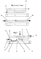
- Fig. 4 shows a very inexpensive variant that can be used depending on the circumstances of the specific application.
- the inflow line 4 seen in the direction 20 of the cooling air, has been arranged behind the coolant cooler 1 and extends over the entire cooling surface thereof. Part of the heat is given off to the cooling air behind the coolant cooler 1 , the cooling capacity of which is thus improved.
- the inflow line 4 can be provided with ribs on the air side.
- FIG. 5 shows a variant similar to FIG. 3, the gas cooler 2 being constructed in the parallel flow type.
- the arrow 22 also indicates the flow in the multi-chamber tubes there.
- FIG. 6, which is similar to FIG. 2 described.
- FIG. 7 shows another very effective variant, in which it is provided that the inflow line 4 is connected to the expansion vessel 30 belonging to the cooling circuit of the motor vehicle, not shown.
- the expansion vessel 30 is arranged in the immediate vicinity of the coolant cooler 1 and thus also of the gas cooler 2 .
- the inflow line 4 is designed as a heat exchanger 31 within the expansion vessel 30 .
- in the expansion vessel 30 there is a heat exchanger 31 around which the coolant flows and through which the CO 2 gas flows.
- the continuation 4a of the inflow line 4 goes from the heat exchanger 31 to the input of the gas cooler 2 .
Abstract
Description
Die Erfindung betrifft eine luftgekühlte Wärmeübertrageranordnung mit einem CO2 - Gaskühler für die Klimaanlage in einem Kraftfahrzeug, in der die Wärmeübertrager in Richtung der vom Ventilator geförderten Kühlluft hintereinander angeordnet sind und der CO2 - Gaskühler in einen Klimakreislauf, mindestens bestehend aus einem Kompressor, einem Verdampfer und einem Expansionsventil mittels entsprechender Zu - und Abströmleitungen für das CO2 eingebunden ist.The invention relates to an air-cooled heat exchanger arrangement with a CO 2 gas cooler for the air conditioning system in a motor vehicle, in which the heat exchangers are arranged one behind the other in the direction of the cooling air conveyed by the fan, and the CO 2 gas cooler into an air conditioning circuit, at least consisting of a compressor, a Evaporator and an expansion valve is integrated by means of appropriate inflow and outflow lines for the CO 2 .
In Klimakreisläufen, die CO2 als Kältemittel verwenden, tritt das CO2 mit einer Temperatur von etwa 150°C in den Gaskühler ein und wird durch den Kühlluftstrom etwa auf Umgebungstemperatur herunter gekühlt. Die relativ hohe Eintrittstemperatur des Gases bringt erhebliche Materialbeanspruchungen des aus Aluminiumblechen gefertigten Gaskühlers mit sich, was bei dessen Auslegung, zusätzlich zu den extrem hohen Drücken, die in CO2 - Kreisläufen vorherrschen, entsprechend zu berücksichtigen ist und sich gewöhnlich in größeren Blechdicken bzw. in druckstabilerer Gestaltung niederschlägt, was ein Kostenfaktor ist.In air conditioning circuits that use CO 2 as a refrigerant, the CO 2 enters the gas cooler at a temperature of around 150 ° C and is cooled down to ambient temperature by the cooling air flow. The relatively high inlet temperature of the gas entails considerable material stresses on the gas cooler made of aluminum sheets, which must be taken into account in its design, in addition to the extremely high pressures that prevail in CO 2 circuits, and usually occur in larger sheet thicknesses or in pressure stable design, which is a cost factor.
Aufgrund dieser bekannten Verhältnisse ist es naheliegend, die Klimaanlage auf einem niedrigeren Temperaturniveau zu betreiben. Das Betreiben der Klimaanlage mit niedrigerem Temperatumiveau führt jedoch entweder zu nicht ausreichender Kühlleistung oder, da dieser Fakt nicht hinnehmbar ist, müßten die Wärmetauscher des Kreislaufs mit größeren oder effizienteren wärmetauschenden Flächen versehen werden. Die Wärmetauscher zu vergrößern ist jedoch kontraproduktiv und auch nicht im Sinne der Kraftfahrzeughersteller, die für solche Anlagen immer kleinere Bauräume verlangen bzw. zur Verfügung stellen.Because of these known conditions, it is obvious to turn the air conditioning on operate at a lower temperature level. Operating the air conditioner however, with a lower temperature level either leads to insufficient Cooling capacity or, since this fact is unacceptable, the heat exchangers would have to the circuit with larger or more efficient heat-exchanging surfaces be provided. However, enlarging the heat exchanger is counterproductive and also not in the sense of the motor vehicle manufacturers who always use such systems require or make available smaller installation spaces.
Bei mit CO2 betreibbaren Klimaanlagen wird gewöhnlich ein Zwischenwärmetauscher im Klimakreislauf vorgesehen, wie es z. B. in der dem Oberbegriff entsprechenden DE 199 18 617 A1 vorgeschlagen wurde, wo der Gaskühler und der Zwischenwärmetauscher zu einer kompakten Baueinheit zusammengefaßt sind. Solche Zwischenwärmetauscher, in denen Gas höherer Temperatur mit dem gleichen Gas niedrigerer Temperatur, welches teilweise eine flüssigen Phase enthält, einem Wärmeaustausch unterzogen werden, sind jedoch nicht zur Reduzierung der Eintrittstemperatur des Gases am Gaskühler geeignet, weil sie im Klimakreislauf funktionsbedingt hinter dem Gaskühler angeordnet werden müssen.In the case of air conditioning systems that can be operated with CO 2 , an intermediate heat exchanger is usually provided in the air conditioning circuit, as is the case, for. B. was proposed in the preamble DE 199 18 617 A1, where the gas cooler and the intermediate heat exchanger are combined into a compact unit. Such intermediate heat exchangers, in which gas of a higher temperature and the same gas of lower temperature, which partly contains a liquid phase, are subjected to heat exchange, are not suitable for reducing the inlet temperature of the gas at the gas cooler, because they are arranged behind the gas cooler in the air conditioning circuit due to their function have to.
Insbesondere im geringen Lastbereich mit vielen Leerlaufphasen des Kraftfahrzeuges besitzen Klimaanlagen eine teilweise unbefriedigende Leistung, weil der vom Motor angetriebene Kompressor in solchen Phasen nur einen relativ geringen Massenstrom des Kältemittels fördern kann.Especially in the low load range with many idle phases of the Air conditioning systems have a partially unsatisfactory performance, because the compressor driven by the engine is only a relative one in such phases can promote low mass flow of the refrigerant.
Demgemäß liegt der Erfindung die Aufgabe zugrunde, mit kostengünstigen und einfachen Mitteln eine Reduzierung der Temperatur des Gases im Bereich des Eintritts in den Gaskühler und die Erhöhung der Wirksamkeit der Klimaanlage insbesondere im geringen Lastbereich zu erreichen.Accordingly, the invention is based, with inexpensive and the task simple means of reducing the temperature of the gas in the range of Entry into the gas cooler and increasing the effectiveness of the air conditioning especially in the low load range.
Gemäß der Erfindung wird das sowohl durch die kennzeichnenden Merkmale des
Anspruchs 1 als auch durch diejenigen des Anspruchs 2 in Verbindung mit dem
Oberbegriff erreicht. Danach ist vorgesehen, dass die als Wärmetauscher
ausgebildete Zuströmleitung des CO2-Gaskühlers in wärmetauschendem Kontakt
mit dem durch den Kühlmittelkühler strömenden Kühlmittel und / oder mit dem
Kühlluftstrom angeordnet ist, um eine Vorkühlung des CO2-Gases zu erreichen.According to the invention this is achieved both by the characterizing features of
Alternativ oder in Kombination (Anspruch 7) ist ferner vorgesehen, dass die am CO2 - Gaseintritt des Gaskühlers angeordneten ersten Wärmetauscherrohre zumindest abschnittsweise in wärmeleitendem Kontakt mit den Wärmetauscherrohren des Kühlmittelkühlers angeordnet sind, um eine Vorkühlung des C02-Gases zu erreichen, wobei die nachfolgenden Wärmetauscherrohre des Gaskühlers ohne wärmeleitendem Kontakt zu den Wärmetauscherrohren angeordnet sind. Der wärmeleitende Kontakt kann darin bestehen, dass sich die erwähnten Rohre unmittelbar berühren aber auch darin, dass sie mittels der Wellrippen verbunden sind. Selbstverständlich können die Rohre auch mittels Wellrippen und mittels unmittelbarer Berührung im wärmeleitenden Kontakt sein.Alternatively or in combination (claim 7) it is also provided that the first heat exchanger tubes arranged at the CO 2 gas inlet of the gas cooler are arranged at least in sections in heat-conducting contact with the heat exchanger tubes of the coolant cooler in order to achieve precooling of the CO 2 gas, the following ones Heat exchanger tubes of the gas cooler are arranged without heat-conducting contact to the heat exchanger tubes. The heat-conducting contact can consist in that the pipes mentioned touch each other directly, but also in that they are connected by means of the corrugated fins. Of course, the tubes can also be in heat-conducting contact by means of corrugated fins and by direct contact.
Die Erfindung macht sich in denkbar einfacher Weise die Erkenntnis zunutze, daß die Temperatur des Motor - Kühlmittels in jedem Fall wesentlich unter der Temperatur des Gases am Eintritt in den Gaskühler liegt. Dadurch kann die Eintrittstemperatur des Gases von etwa 150°C auf etwa Kühlmitteltemperatur abgesenkt werden. Demzufolge kann bei der Auslegung solcher Gaskühler weniger Rücksicht auf hohe Temperaturen genommen werden, bzw. der durch hohe Temperaturen verursachte Anteil muß nicht mehr so sehr beachtet werden. The invention makes use of the knowledge in a very simple manner that the temperature of the engine coolant is in any case significantly below the Temperature of the gas at the inlet to the gas cooler. This allows the Entry temperature of the gas from about 150 ° C to about coolant temperature be lowered. Accordingly, when designing such gas coolers less consideration for high temperatures, or due to The portion caused by high temperatures no longer has to be considered as much.
Mit anderen Worten, der Gaskühler muß lediglich unter dem Gesichtspunkt der maximal auftretenden Drücke ausgelegt werden. Temperaturwechselbelastungen spielen nur noch eine untergeordnete oder zumindest eine geringere Rolle.In other words, the gas cooler only needs to be viewed from the point of view of maximum occurring pressures can be designed. Thermal cycling only play a subordinate or at least a minor role.
Ferner wurden die durch hohe Temperaturunterschiede zwischen der Kühlluft und dem Gas verursachten und immer wieder zu Problemen führenden Materialspannungen, die sich in Rissen oder Brüchen manifestieren, zumindest teilweise abgeschwächt. Solche Risse treten besonders in den Verbindungen der Flachrohrenden in den Öffnungen der Sammler auf und zwar derjenigen Verbindungen, die in der Nähe des Gaseintritts liegen. Ein wesentlicher weiterer Vorteil der erfindungsgemäßen Vorkühlung des CO2 - Gases liegt darin, dass der Kühlluft, die durch den Gaskühler und den Kühlmittelkühler geblasen wird, beim Passieren des Gaskühlers nicht so viel ihrer Kühlfähigkeit entzogen wird. Sie besitzt deshalb beim Auftreffen auf das Kühlnetz des Kühlmittelkühlers eine niedrigere Temperatur als sie ohne Vorkühlung des Gases besitzen würde, was dort dem Wärmeaustausch mehr Effizienz verleiht.Furthermore, the material stresses caused by high temperature differences between the cooling air and the gas, which repeatedly lead to problems, and which manifest themselves in cracks or breaks, were at least partially weakened. Such cracks occur particularly in the connections of the flat tube ends in the openings of the collectors, namely those connections which are close to the gas inlet. A significant further advantage of the precooling of the CO 2 gas according to the invention is that the cooling air which is blown through the gas cooler and the coolant cooler is not as much removed from its cooling capacity as it passes through the gas cooler. It therefore has a lower temperature when it hits the cooling network of the coolant cooler than it would have without pre-cooling the gas, which gives the heat exchange more efficiency there.
Besonders wirksam ist die Erfindung im geringen Lastbereich des Motors des Kraftfahrzeuges und in Startphasen desselben, weil, selbst bei hohen Außentemperaturen, der Motor zunächst (ohne Kühlung) warm laufen muß, um effizienter und umweltfreundlicher zu arbeiten, was einen gewissen Zeitraum erfordert. Von der Klimaanlage wird bei hohen Außentemperaturen jedoch eine möglichst sofortige Kühlung verlangt. Deshalb trägt die Vorkühlung des CO2-Gases mittels des in den erwähnten Phasen relativ kühlen Kühlmittels sowohl dazu bei, daß sich das Kühlmittel schneller erwärmt als auch dazu, daß die Klimaanlage ihre Kühlwirkung schneller entfaltet.The invention is particularly effective in the low load range of the engine of the motor vehicle and in the starting phases of the same, because, even at high outside temperatures, the engine must first run warm (without cooling) in order to work more efficiently and more environmentally friendly, which requires a certain period of time. In the case of high outside temperatures, however, the air conditioning system is required to cool as immediately as possible. Therefore, the pre-cooling of the CO 2 gas by means of the coolant which is relatively cool in the phases mentioned both contributes to the coolant heating up more quickly and also to the air conditioning system developing its cooling action more quickly.
Der Gaskühler selbst arbeitet in einer bevorzugten Bauart nach dem Kreuzgegenstrom - Prinzip und ist deshalb sehr effizient im Wärmeaustausch. Er besteht aus serpentinenartig gebogenen Mehrkammer - Flachrohren, wobei die einzelnen Serpentinen eines jeden Mehrkammer - Flachrohres horizontal bzw. inThe gas cooler itself works in a preferred design according to the Cross-countercurrent principle and is therefore very efficient in heat exchange. He consists of multi - chamber flat tubes bent like a serpentine individual serpentines of each multi - chamber flat tube horizontally or in
Kühlluft - Strömungsrichtung hintereinander liegend angeordnet sind. Jedes Mehrkammer - Flachrohr bildet also eine Ebene und liegt mit einer seiner Schmalseiten in Kühlluft - Strömungsrichtung. Zwischen den serpentinenartig gebogenen Mehrkammer- Flachrohren sind Wellrippen oder dergleichen angeordnet, durch die die Kühlluft hindurchströmt. Die beiden Sammelrohre des Gaskühlers können an einer Seite des so gebildeten Kühlnetzes oder an gegenüberliegenden Seiten angeordnet sein.Cooling air flow direction are arranged one behind the other. each Multi-chamber flat tube thus forms a plane and lies with one of its Narrow sides in cooling air - flow direction. Between the serpentine curved multi-chamber flat tubes are corrugated fins or the like arranged through which the cooling air flows. The two manifolds of the Gas coolers can on one side of the cooling network or so formed opposite sides can be arranged.
Eine andere Bauart des Gaskühlers (Anspruch 11) arbeitet nach dem Parallelfluß - Prinzip. Diese Bauart ist ähnlich derjenigen, die beispielsweise im der Anmelderin gehörenden EP 583 851 B1 für einen Kondensator beschrieben und gezeigt wurde, der in einem konventionellen Klimakreislauf angeordnet ist. Wegen weiterer Einzelheiten dieser Bauart wird auf das genannte EP verwiesen, wodurch die Einzelheiten Bestandteil der vorliegenden Anmeldung sein sollen.Another type of gas cooler (claim 11) works according to the parallel flow - Principle. This type of construction is similar to that used, for example, by the applicant EP 583 851 B1 described and shown for a capacitor which is arranged in a conventional climate cycle. Because of more Details of this type are referred to the EP mentioned, whereby the Details should be part of the present application.
Die Ansprüche 2 und 3 betreffen baulich besonders einfache Maßnahmen, die
jedoch bereits zu wirksamer Absenkung der Eintrittstemperatur des Gases führen.
Die Anordnung der Zuströmleitung vor oder hinter dem Kühlmittelkühler stellt
darüber hinaus eine Maßnahme dar, die in bestehenden Systemen schnell und
einfach nachrüstbar ist. Die Zuströmleitung kann als beripptes Rohr ausgebildet
sein.The
Die Maßnahmen aus den Ansprüchen 4 und 5 sind etwas aufwendiger, weil die
Zuströmleitung als Wärmetauscher ausgebildet ist, der in einem Sammelkasten
des Kühlmittelkühlers oder im Ausgleichsgefäß für das Kühlmittel eingebaut
werden muß. Sie sind jedoch hinsichtlich der Höhe der Temperaturabsenkung des
Gases die wirksamste Maßnahme.The measures from
Der Anspruch 7 sieht zur weiteren Verbesserung der Vorkühlung vor, die einzelnen
Maßnahmen zu kombinieren. Beispielsweise kann die Zuströmleitung für das CO2
ein beripptes Rohr sein, dass sich über das Kühlnetz des Kühlmittelkühlers
erstreckt, also im Kühlluftstrom angeordnet ist. Diese Zuströmleitung kann zum
abströmseitigen Sammelkasten des Kühlmittelkühlers gehen und zwar dort zum
Eingang eines wassergekühlten Vorkühlers, der im Sammelkasten angeordnet und
vom Wasser bzw. vom Kühlmittel umströmt ist. Damit könnte bereits die
Eintrittstemperatur in den Vorkühler bzw. in den Wärmetauscher reduziert werden.
Durch diese und weitere in dieselbe Richtung weisende Maßnahmen wird eine deutliche Reduzierung der Eintrittstemperatur des CO2 - Gases in den Gaskühler erreicht. Weitere Merkmale gehen aus den restlichen Patentansprüchen hervor.These and other measures pointing in the same direction achieve a significant reduction in the entry temperature of the CO 2 gas into the gas cooler. Further features emerge from the remaining claims.
Der Kühlmittelkühler ist ein Querstromkühler, bei dem - in Einbaulage im Kraftfahrzeug gesehen - die Wärmetauscherrohre (Flachrohre) horizontal und die Sammelkästen an beiden Enden der Flachrohre vertikal dazu angeordnet sind. The coolant cooler is a cross flow cooler, in which - in the installation position in Motor vehicle seen - the heat exchanger tubes (flat tubes) horizontally and the Collecting boxes are arranged vertically at both ends of the flat tubes.
Die Erfindung wird nachfolgend in Ausführungsbeispielen erläutert, wozu auf die
beiliegenden Figuren Bezug genommen wird, die Folgendes - lediglich in
Abstraktionen - zeigen:
Sämtliche Darstellungen sind lediglich schematische Draufsichten auf die
Wärmeübertrageranordnung. Die Zeichnungsebene liegt parallel mit der Breitseite
der Flachrohre 6, 12 des Gaskühlers 2 und des Kühlmittelkühlers 1. All representations are merely schematic top views of the heat exchanger arrangement. The drawing plane is parallel to the broad side of the
Der CO2 - Gaskühler 2 und der Kühlmittelkühler 1 liegen in durch die Pfeile 20
markierter Kühlluftströmungsrichtung hintereinander im nicht dargestellten
Motorraum eines Kraftfahrzeuges. Die Kühlluft 20 wird durch einen saugenden
Ventilator 3, der in Fig. 4 angedeutet ist, durch den Gaskühler 2 und den
Kühlmittelkühler 1 gefördert, um sowohl das gasförmige CO2 im Gaskühler 2 als
auch das Kühlmittel des Motors zu kühlen. Der Gaskühler 2 und der
Kühlmittelkühler 1 können in nicht gezeigter, weil hinreichend bekannter und im
vorliegenden Zusammenhang unwesentlicher Weise miteinander lösbar oder
unlösbar verbunden sein. Im Stand der Technik gemäß Fig. 1, liegt keine gezielte,
d. h. auf die Erreichung eines Vorteils gerichtete wärmetauschende Beziehung
zwischen dem Gaskühler 2 und dem Kühlmittelkühler 1 vor. Die Temperatur des
Gases am Eintritt 14 des Gaskühlers 2 ist dementsprechend hoch. Die
Zuströmleitung 4 zum Gaskühler 2 ist beim Stand der Technik so verlegt, wie es
die Einbaubedingungen im Motorraum des Kraftfahrzeuges gerade gestatten. Eine
Temperaturabsenkung des Kältemittels zwischen Kompressor und Gaskühler ist
nicht vorgesehen. Die weiteren Bestandteile des Klimakreislaufs sind nicht gezeigt,
weil derselbe zum Stand der Technik gehört.The CO 2 gas cooler 2 and the
In den abstrakten Darstellungen stellen der Gaseintritt 14 und der Gasaustritt 16
gleichzeitig die Sammelrohre des Gaskühlers 2 dar. Zwischen den Sammelrohren
14 und 16, die in diesen Ausführungsbeispielen an gegenüberliegenden Seiten
angeordnet sind, erstrecken sich serpentinenartig gebogene oder gerade flache
Mehrkammerrohre 6, zwischen denen sich nicht gezeigte Wellrippen oder
dergleichen befinden, durch die die Kühlluft hindurchströmt. Bei den
Mehrkammerrohren 6 handelt es sich um Flachrohre, die mit ihren Schmalseiten
senkrecht zur Kühlluftströmungsrichtung 20 bzw. mit ihren Breitseiten in der
Zeichnungsebene liegend angeordnet sind. Senkrecht zur Zeichnungsebene sind
solche Mehrkammerrohre 6 abwechselnd mit den nicht gezeigten Wellrippen
gestapelt und bilden das Kühlnetz des Gaskühlers 2. Die Mehrkammerrohre 6 sind
im gezeigten Ausführungsbeispiel der Fig. 2 bis 4 zweimal um jeweils 180°
umgebogen, was schematisch mit den Biegungen 25 angezeigt wurde. Das
Kreuzgegenstromprinzip soll durch die Strömungspfeile 22 angezeigt sein, die die
Durchströmung in den Mehrkammerrohren 6 in der gezeigten Ebene verdeutlichen.
Am Austritt 16 soll die Temperatur des Gases etwa auf Umgebungstemperatur
liegen, was durch den Wärmeaustausch mit der Kühlluft erreicht wird, die dadurch
bereits einen Teil ihrer Kühlfähigkeit eingebüßt hat, bevor sie auf das Kühlnetz des
Kühlmittelkühlers 1 trifft, das aus Flachrohren 10 und dazwischen angeordneten
nicht gezeigten Wellrippen oder dergleichen besteht.In the abstract representations, the
Gemäß einer in Fig. 2 dargestellten ersten Variante wird der erwähnte Nachteil
dadurch beseitigt, dass das am Gaseintritt 14 des Gaskühlers 2 liegende erste
Wärmetauscherrohr 15 über einen Längenabschnitt in wärmeleitendem Kontakt mit
einem Flachrohr 12 des Kühlmittelkühlers 1 steht. Dazu wurde das
Wärmetauscherrohr 15 mit zwei Abbiegungen 21 versehen, damit es möglichst gut
leitend über einen Längenabschnitt am Flachrohr 12 anliegt. Selbstverständlich
können die nicht gezeigten Wellrippen zwischen den Flachrohren 12 das
Wärmetauscherrohr 15 zusätzlich umschließen, um die Intensität desAccording to a first variant shown in FIG. 2, the disadvantage mentioned is eliminated in that the first
Wärmeaustausches zu fördem. Bei einem nicht gezeigten Ausführungsbeispiel
wurden die ersten drei am Eintritt des Gaskühlers 2 angeschlossenen
Wärmetauscherrohre 6 derartig mit den Flachrohren 12 des Kühlmittelkühlers 1
verbunden. Die vom nicht gezeigten Kompressor kommende Zuströmleitung 4, die
Gas hoher Temperatur und hohen Drucks transportiert, wurde in Fig. 2 lediglich als
Pfeil dargestellt. Sie könnte sowohl beliebig verlegt sein als auch so wie in den Fig.
3 und 4 angeordnet werden. Femer steht die Zuströmleitung 4 selbst, in einem
ebenfalls nicht gezeigten anderen Ausführungsbeispiel, ähnlich der in Fig. 2
gezeigten Variante, mit dem Flachrohr 6 des Kühlmittelkühlers 1 in
wärmeleitendem Kontakt. To promote heat exchange. In an exemplary embodiment not shown, the first three
Die Fig. 3 zeigt ebenfalls in sehr schematischer Weise die aus der Sicht eines
effizienten Wärmeaustausches beste Variante. Hier wurde ein nicht gezeigter
sondern nur mit dem Bezugszeichen 9 markierter Wärmetauscher, sozusagen ein
Gas - Vorkühler, im Sammelkasten 8 auf der Abströmseite des Kühlmittelkühlers 1
eingebaut. Die Zuführleitung 4 ist an den nicht gezeigten Eingang des3 also shows in a very schematic manner the best variant from the point of view of an efficient heat exchange. Here, a heat exchanger, not shown but only marked with the
Wärmetauschers 9 angeschlossen. Nach dem Durchströmen des Wärmetauschers
9 und nach erfolgtem Wärmeaustausch mit dem Kühlmittel des Kraftfahrzeuges
tritt das CO2 - Gas über die Leitung 4a, die die Fortsetzung der Zuführleitung 4 ist,
in den Gaskühler 2 ein. Der Einbau von Wärmetauschern 9 in Sammelkästen 8
von Kühlmittelkühlern 1 zur Kühlung von Betriebsstoffen, ist seit langem bestens
bekannter Stand der Technik, weshalb sich hierzu nähere Erläuterungen durch
Verweis auf solche Veröffentlichungen erübrigen. Beispielsweise kann der
Wärmetauscher 9 ähnlich dem Wärmetauscher sein, der aus dem der Anmelderin
gehörenden EP 678 661 B1 bekannt ist, welcher dort im abströmseitigen
Sammelkasten des Kühlmittelkühlers angeordnet und ein wassergekühlter
Kondensator ist.
Die Fig. 4 zeigt eine sehr kostengünstige Variante, die in Abhängigkeit von den
Gegebenheiten des konkreten Anwendungsfalls benutzt werden kann. Dabei ist
die Zuströmleitung 4 in Richtung 20 der Kühlluft gesehen hinter dem
Kühlmittelkühler 1 angeordnet worden und erstreckt sich über die gesamte
Kühlfläche desselben. Ein Teil der Wärme wird an die Kühlluft hinter dem
Kühlmittelkühler 1 abgegeben, dessen Kühlleistung somit verbessert ist. Zur
Verbesserung der Wärmeübertragung kann die Zuströmleitung 4 luftseitig mit
Rippen versehen sein.Fig. 4 shows a very inexpensive variant that can be used depending on the circumstances of the specific application. The
Es wurde nicht in einer weiteren Figur dargestellt, ist jedoch aus den Fig. 2, 3 und 4 für den Fachmann vollständig verständlich, dass die dort gezeigten Varianten in einem Anwendungsfall auch beliebig kombinierbar sind, um eine gewünschte deutlichere Reduzierung der Eintrittstemperatur des Gases zu erzielen.It was not shown in another figure, but is from FIGS. 2, 3 and 4 fully understandable for the person skilled in the art that the variants shown there in an application can also be combined as desired to create a desired one to achieve a clear reduction in the inlet temperature of the gas.
Die Fig. 5 zeigt eine der Fig. 3 ähnliche Variante, wobei der Gaskühler 2 in
Parallelflußbauart ausgebildet wurde. Auch dort zeigt der Pfeil 22 die
Durchströmung in den Mehrkammerrohren an. Es wurde ein Doppelpfeil
eingezeichnet, womit gezeigt sein soll, dass es Gruppen von Mehrkammerrohren
gibt, wobei in einer Gruppe das Kältemittel beispielsweise von links nach rechts
strömt und in der benachbarten, über oder unter der zuerst genannten Gruppe
angeordneten nächsten Gruppe, von rechts nach links, usw.. Dasselbe trifft auf die
Fig. 6 zu, die ähnlich der beschriebenen Fig. 2 ist.FIG. 5 shows a variant similar to FIG. 3, the
Die Fig. 7 zeigt eine weitere sehr wirksame Variante, bei der vorgesehen ist, die
Zuströmleitung 4 an das zum nicht gezeigten Kühlkreislauf des Kraftfahrzeuges
gehörenden Ausdehnungsgefäß 30 anzuschließen. Das Ausdehnungsgefäß 30 ist
in unmittelbarer Nähe zum Kühlmittelkühler 1 und damit auch zum Gaskühler 2
angeordnet. Innerhalb des Ausdehnungsgefäßes 30 ist die Zuströmleitung 4 als
Wärmetauscher 31 ausgebildet. Mit anderen Worten, in dem Ausdehnungsgefäß
30 befindet sich ein vom Kühlmittel umströmter und von dem C02-Gas
durchströmter Wärmetauscher 31. Von dem Wärmetauscher 31 geht die
Fortsetzung 4a der Zuströmleitung 4 zum Eingang des Gaskühlers 2.FIG. 7 shows another very effective variant, in which it is provided that the
Claims (11)
dadurch gekennzeichnet, dass
die als Wärmetauscher (9; 31) ausgebildete Zuströmleitung (4) des C02-Gaskühlers (2) in wärmeleitendem Kontakt mit dem durch den Kühlmittelkühler (1) strömenden Kühlmittel und / oder mit dem Kühlluftstrom angeordnet ist, um eine Vorkühlung des CO2-Gases zu erreichen.Air-cooled heat exchanger arrangement with a coolant cooler (1) and a CO 2 gas cooler (2) for the air conditioning system in a motor vehicle, in which the heat exchangers (1; 2) are arranged one behind the other in the direction of the cooling air flow conveyed by the fan (3), the front CO 2 gas cooler (2) arranged to the coolant cooler (1) is integrated in an air conditioning circuit, at least consisting of a compressor, an evaporator and an expansion valve by means of corresponding inlet (4) and outflow lines (5) for the CO 2 ,
characterized in that
the inflow line (4) of the CO 2 gas cooler (2), which is designed as a heat exchanger (9; 31), is arranged in heat-conducting contact with the coolant flowing through the coolant cooler (1) and / or with the cooling air flow in order to precool the CO 2 gas to reach.
dadurch gekennzeichnet, dass
die am CO2 - Gaseintritt des Gaskühlers (2) angeordneten ersten Wärmetauscherrohre (15) zumindest abschnittsweise in wärmeleitendem Kontakt mit den Wärmetauscherrohren (12) des Kühlmittelkühlers (1) angeordnet sind, um eine Vorkühlung des C02-Gases zu erreichen, wobei die nachfolgenden Wärmetauscherrohre (6) des Gaskühlers (2) keinen wärmeleitenden Kontakt mit den Wärmetauscherrohren (12) besitzen.Air-cooled heat exchanger arrangement with a coolant cooler (1) and a CO 2 gas cooler (2) for the air conditioning system in a motor vehicle, in which the heat exchangers (1; 2) are arranged one behind the other in the direction of the cooling air flow conveyed by the fan (3), the front CO 2 gas cooler (2) arranged to the coolant cooler (1) is integrated in an air conditioning circuit, at least consisting of a compressor, an evaporator and an expansion valve by means of corresponding inlet (4) and outflow lines (5) for the CO 2 ,
characterized in that
the first heat exchanger tubes (15) arranged at the CO 2 gas inlet of the gas cooler (2) are arranged at least in sections in heat-conducting contact with the heat exchanger tubes (12) of the coolant cooler (1) in order to achieve precooling of the CO 2 gas, the subsequent heat exchanger tubes (6) of the gas cooler (2) have no heat-conducting contact with the heat exchanger tubes (12).
dadurch gekennzeichnet, dass
die Wärmeübertrageranordnung eine Kombinat der kennzeichnenden Merkmale aus den Ansprüchen 1 und 2 aufweist.Air-cooled heat exchanger arrangement with a coolant cooler (1) and a CO 2 gas cooler (2) for the air conditioning system in a motor vehicle, in which the heat exchangers (1; 2) are arranged one behind the other in the direction of the cooling air flow conveyed by the fan (3), the front CO 2 gas cooler (2) arranged to the coolant cooler (1) is integrated in an air conditioning circuit, at least consisting of a compressor, an evaporator and an expansion valve by means of corresponding inlet (4) and outflow lines (5) for the CO 2 ,
characterized in that
the heat exchanger arrangement has a combination of the characterizing features of claims 1 and 2.
Applications Claiming Priority (2)
| Application Number | Priority Date | Filing Date | Title |
|---|---|---|---|
| DE10137907 | 2001-08-02 | ||
| DE10137907A DE10137907A1 (en) | 2001-08-02 | 2001-08-02 | Air cooled heat transfer arrangement |
Publications (2)
| Publication Number | Publication Date |
|---|---|
| EP1281545A1 true EP1281545A1 (en) | 2003-02-05 |
| EP1281545B1 EP1281545B1 (en) | 2004-11-24 |
Family
ID=7694131
Family Applications (1)
| Application Number | Title | Priority Date | Filing Date |
|---|---|---|---|
| EP02012976A Expired - Fee Related EP1281545B1 (en) | 2001-08-02 | 2002-06-12 | Air cooled heat exchanger arrangement comprising a CO2 gas cooler |
Country Status (4)
| Country | Link |
|---|---|
| US (1) | US6772602B2 (en) |
| EP (1) | EP1281545B1 (en) |
| DE (2) | DE10137907A1 (en) |
| ES (1) | ES2233744T3 (en) |
Cited By (4)
| Publication number | Priority date | Publication date | Assignee | Title |
|---|---|---|---|---|
| EP1600314A1 (en) | 2004-05-15 | 2005-11-30 | Modine Manufacturing Company | Arrangement and operating method in a refrigerant circuit |
| EP1878602A1 (en) * | 2006-07-15 | 2008-01-16 | Delphi Technologies, Inc. | Cooling module for a vehicle |
| CN103497124A (en) * | 2013-09-06 | 2014-01-08 | 安徽淮化股份有限公司 | Method for reducing carbon dioxide gas temperature by using air-separation liquid product cold energy |
| DE102011052776B4 (en) * | 2011-04-27 | 2016-12-29 | Dürr Thermea Gmbh | Supercritical heat pump |
Families Citing this family (14)
| Publication number | Priority date | Publication date | Assignee | Title |
|---|---|---|---|---|
| JP2006044424A (en) * | 2004-08-03 | 2006-02-16 | Sanden Corp | Vehicular air-conditioner |
| US7455136B2 (en) * | 2004-09-09 | 2008-11-25 | Gm Global Technology Operations, Inc. | Cooling system for a rearward portion of a vehicle and method of cooling |
| US8596556B2 (en) * | 2005-02-22 | 2013-12-03 | Vehicle Enhancement Labs | Radiator and air cooler mister |
| CN101142452A (en) * | 2005-03-18 | 2008-03-12 | 开利商业冷藏公司 | Flat tube single snake-like co2 heat exchanger |
| FR2928448B1 (en) * | 2008-03-04 | 2015-05-01 | Valeo Systemes Thermiques | IMPROVED GAS COOLER |
| US8225852B2 (en) * | 2008-04-30 | 2012-07-24 | Dana Canada Corporation | Heat exchanger using air and liquid as coolants |
| CN103561977B (en) * | 2011-06-01 | 2016-03-09 | 三菱电机株式会社 | Air conditioner for vehicles |
| KR20130050051A (en) * | 2011-11-07 | 2013-05-15 | 현대자동차주식회사 | Cooling apparatus for vehicle |
| US9316141B2 (en) | 2013-02-15 | 2016-04-19 | Enis Pilavdzic | Engine energy management system |
| DE102013114872B4 (en) | 2013-06-07 | 2023-09-21 | Halla Visteon Climate Control Corp. | Radiator for vehicle |
| KR20140143650A (en) * | 2013-06-07 | 2014-12-17 | 현대자동차주식회사 | Cooling module for vehicle |
| KR101416419B1 (en) * | 2013-06-27 | 2014-07-08 | 현대자동차 주식회사 | Radiator for vehicle |
| KR102182343B1 (en) * | 2015-01-12 | 2020-11-25 | 한온시스템 주식회사 | Heat pump system for vehicle |
| FR3052109B1 (en) * | 2016-06-03 | 2019-04-19 | Valeo Systemes Thermiques | HEAT EXCHANGE MODULE, FRONT PANEL AND CORRESPONDING MOTOR VEHICLE |
Citations (4)
| Publication number | Priority date | Publication date | Assignee | Title |
|---|---|---|---|---|
| US3479834A (en) * | 1968-04-10 | 1969-11-25 | Capitol Refrigeration Inc | Method and apparatus for air conditioning automobiles and the like |
| DE19843928A1 (en) * | 1997-09-29 | 1999-04-08 | Aisin Seiki | Front end module for vehicle with condenser having front and rear surfaces |
| EP1046524A2 (en) * | 1999-04-23 | 2000-10-25 | Valeo Klimatechnik GmbH | High pressure gas cooler for a refrigerant circuit of a motor-vehicle air-conditioning system |
| EP1068967A1 (en) * | 1999-07-12 | 2001-01-17 | Valeo Climatisation | Heating-air conditioning device for a motor vehicle |
Family Cites Families (4)
| Publication number | Priority date | Publication date | Assignee | Title |
|---|---|---|---|---|
| US3606762A (en) * | 1969-10-24 | 1971-09-21 | William E Anglin | Method and apparatus for air conditioning automobiles and the like |
| CA1317772C (en) * | 1985-10-02 | 1993-05-18 | Leon A. Guntly | Condenser with small hydraulic diameter flow path |
| US5408843A (en) * | 1994-03-24 | 1995-04-25 | Modine Manufacturing Co. | Vehicular cooling system and liquid cooled condenser therefor |
| DE19830757A1 (en) * | 1998-07-09 | 2000-01-13 | Behr Gmbh & Co | Air conditioning system especially for a motor vehicle |
-
2001
- 2001-08-02 DE DE10137907A patent/DE10137907A1/en not_active Withdrawn
-
2002
- 2002-06-12 DE DE50201603T patent/DE50201603D1/en not_active Expired - Lifetime
- 2002-06-12 ES ES02012976T patent/ES2233744T3/en not_active Expired - Lifetime
- 2002-06-12 EP EP02012976A patent/EP1281545B1/en not_active Expired - Fee Related
- 2002-07-29 US US10/207,633 patent/US6772602B2/en not_active Expired - Fee Related
Patent Citations (4)
| Publication number | Priority date | Publication date | Assignee | Title |
|---|---|---|---|---|
| US3479834A (en) * | 1968-04-10 | 1969-11-25 | Capitol Refrigeration Inc | Method and apparatus for air conditioning automobiles and the like |
| DE19843928A1 (en) * | 1997-09-29 | 1999-04-08 | Aisin Seiki | Front end module for vehicle with condenser having front and rear surfaces |
| EP1046524A2 (en) * | 1999-04-23 | 2000-10-25 | Valeo Klimatechnik GmbH | High pressure gas cooler for a refrigerant circuit of a motor-vehicle air-conditioning system |
| EP1068967A1 (en) * | 1999-07-12 | 2001-01-17 | Valeo Climatisation | Heating-air conditioning device for a motor vehicle |
Cited By (5)
| Publication number | Priority date | Publication date | Assignee | Title |
|---|---|---|---|---|
| EP1600314A1 (en) | 2004-05-15 | 2005-11-30 | Modine Manufacturing Company | Arrangement and operating method in a refrigerant circuit |
| DE102004024255A1 (en) * | 2004-05-15 | 2005-12-01 | Modine Manufacturing Co., Racine | Arrangement in a refrigerant circuit and working method |
| EP1878602A1 (en) * | 2006-07-15 | 2008-01-16 | Delphi Technologies, Inc. | Cooling module for a vehicle |
| DE102011052776B4 (en) * | 2011-04-27 | 2016-12-29 | Dürr Thermea Gmbh | Supercritical heat pump |
| CN103497124A (en) * | 2013-09-06 | 2014-01-08 | 安徽淮化股份有限公司 | Method for reducing carbon dioxide gas temperature by using air-separation liquid product cold energy |
Also Published As
| Publication number | Publication date |
|---|---|
| DE50201603D1 (en) | 2004-12-30 |
| ES2233744T3 (en) | 2005-06-16 |
| US6772602B2 (en) | 2004-08-10 |
| DE10137907A1 (en) | 2003-02-20 |
| EP1281545B1 (en) | 2004-11-24 |
| US20030041617A1 (en) | 2003-03-06 |
Similar Documents
| Publication | Publication Date | Title |
|---|---|---|
| EP1281545B1 (en) | Air cooled heat exchanger arrangement comprising a CO2 gas cooler | |
| EP1279805B1 (en) | Air-cooled intake air cooler | |
| DE102010048015B4 (en) | Plant with a heat exchanger | |
| DE60032197T2 (en) | Heating air conditioning for motor vehicles | |
| DE102012215411A1 (en) | Evaporator with cold storage function | |
| EP2140219B1 (en) | Motor vehicle | |
| EP2225528B1 (en) | Heat exchange system | |
| DE102010055972A1 (en) | Evaporator with cold storage function | |
| DE112012005066T5 (en) | Heat exchange system | |
| DE102012216424A1 (en) | Cooling unit of an air conditioning device for a vehicle | |
| DE60126237T2 (en) | downflow | |
| WO2010040635A1 (en) | Heat exchanger assembly and method for the operation thereof | |
| WO2009077226A1 (en) | Heat exchange system | |
| DE102007031824A1 (en) | Heat exchanger tube comprises first thin sheet of material partially forming broad and narrow sides of tube body and partially enclosing an interior space, and second sheet of material partially forming fin brazed to tube body | |
| DE102013223697A1 (en) | Cooling module for a vehicle | |
| DE102019128941B4 (en) | Front bumper with integrated heat exchanger | |
| DE102005027674A1 (en) | Air conditioning for vehicle use | |
| EP1600314B1 (en) | Arrangement and operating method in a refrigerant circuit | |
| EP1272804A2 (en) | Heat exchanger for a co2 vehicle air conditioner | |
| DE102004001786A1 (en) | Heat exchanger, especially for supercritical refrigeration cycle | |
| AT410006B (en) | COOLING DEVICE FOR INTERNAL COMBUSTION ENGINES | |
| EP1632742B1 (en) | Heat exchanger, more particularly for air conditioning system | |
| EP1734324A2 (en) | Variable internal heat exchanger | |
| EP1764571B1 (en) | Heat exchanger, especially radiator, for air conditioning system | |
| EP1538407B1 (en) | Condenser |
Legal Events
| Date | Code | Title | Description |
|---|---|---|---|
| PUAI | Public reference made under article 153(3) epc to a published international application that has entered the european phase |
Free format text: ORIGINAL CODE: 0009012 |
|
| AK | Designated contracting states |
Designated state(s): AT BE CH CY DE DK ES FI FR GB GR IE IT LI LU MC NL PT SE TR |
|
| AX | Request for extension of the european patent |
Extension state: AL LT LV MK RO SI |
|
| 17P | Request for examination filed |
Effective date: 20030805 |
|
| AKX | Designation fees paid |
Designated state(s): AT BE CH CY DE DK ES FI FR GB GR IE IT LI LU MC NL PT SE TR |
|
| 17Q | First examination report despatched |
Effective date: 20040212 |
|
| GRAP | Despatch of communication of intention to grant a patent |
Free format text: ORIGINAL CODE: EPIDOSNIGR1 |
|
| RAP1 | Party data changed (applicant data changed or rights of an application transferred) |
Owner name: MODINE MANUFACTURING COMPANY |
|
| RBV | Designated contracting states (corrected) |
Designated state(s): DE ES FR GB IT SE |
|
| GRAS | Grant fee paid |
Free format text: ORIGINAL CODE: EPIDOSNIGR3 |
|
| GRAA | (expected) grant |
Free format text: ORIGINAL CODE: 0009210 |
|
| AK | Designated contracting states |
Kind code of ref document: B1 Designated state(s): DE ES FR GB IT SE |
|
| REG | Reference to a national code |
Ref country code: GB Ref legal event code: FG4D Free format text: NOT ENGLISH |
|
| REF | Corresponds to: |
Ref document number: 50201603 Country of ref document: DE Date of ref document: 20041230 Kind code of ref document: P |
|
| REG | Reference to a national code |
Ref country code: IE Ref legal event code: FG4D Free format text: GERMAN |
|
| REG | Reference to a national code |
Ref country code: SE Ref legal event code: TRGR |
|
| GBT | Gb: translation of ep patent filed (gb section 77(6)(a)/1977) |
Effective date: 20050310 |
|
| REG | Reference to a national code |
Ref country code: ES Ref legal event code: FG2A Ref document number: 2233744 Country of ref document: ES Kind code of ref document: T3 |
|
| REG | Reference to a national code |
Ref country code: IE Ref legal event code: FD4D |
|
| PLBE | No opposition filed within time limit |
Free format text: ORIGINAL CODE: 0009261 |
|
| STAA | Information on the status of an ep patent application or granted ep patent |
Free format text: STATUS: NO OPPOSITION FILED WITHIN TIME LIMIT |
|
| ET | Fr: translation filed | ||
| 26N | No opposition filed |
Effective date: 20050825 |
|
| PGFP | Annual fee paid to national office [announced via postgrant information from national office to epo] |
Ref country code: SE Payment date: 20070625 Year of fee payment: 6 |
|
| PGFP | Annual fee paid to national office [announced via postgrant information from national office to epo] |
Ref country code: IT Payment date: 20070628 Year of fee payment: 6 |
|
| EUG | Se: european patent has lapsed | ||
| PG25 | Lapsed in a contracting state [announced via postgrant information from national office to epo] |
Ref country code: IT Free format text: LAPSE BECAUSE OF NON-PAYMENT OF DUE FEES Effective date: 20080612 |
|
| PG25 | Lapsed in a contracting state [announced via postgrant information from national office to epo] |
Ref country code: SE Free format text: LAPSE BECAUSE OF NON-PAYMENT OF DUE FEES Effective date: 20080613 |
|
| PGFP | Annual fee paid to national office [announced via postgrant information from national office to epo] |
Ref country code: GB Payment date: 20140627 Year of fee payment: 13 |
|
| PGFP | Annual fee paid to national office [announced via postgrant information from national office to epo] |
Ref country code: ES Payment date: 20140611 Year of fee payment: 13 |
|
| PGFP | Annual fee paid to national office [announced via postgrant information from national office to epo] |
Ref country code: FR Payment date: 20140623 Year of fee payment: 13 |
|
| GBPC | Gb: european patent ceased through non-payment of renewal fee |
Effective date: 20150612 |
|
| REG | Reference to a national code |
Ref country code: FR Ref legal event code: ST Effective date: 20160229 |
|
| PG25 | Lapsed in a contracting state [announced via postgrant information from national office to epo] |
Ref country code: GB Free format text: LAPSE BECAUSE OF NON-PAYMENT OF DUE FEES Effective date: 20150612 |
|
| PG25 | Lapsed in a contracting state [announced via postgrant information from national office to epo] |
Ref country code: FR Free format text: LAPSE BECAUSE OF NON-PAYMENT OF DUE FEES Effective date: 20150630 |
|
| PGFP | Annual fee paid to national office [announced via postgrant information from national office to epo] |
Ref country code: DE Payment date: 20160628 Year of fee payment: 15 |
|
| REG | Reference to a national code |
Ref country code: ES Ref legal event code: FD2A Effective date: 20170301 |
|
| PG25 | Lapsed in a contracting state [announced via postgrant information from national office to epo] |
Ref country code: ES Free format text: LAPSE BECAUSE OF NON-PAYMENT OF DUE FEES Effective date: 20150613 |
|
| REG | Reference to a national code |
Ref country code: DE Ref legal event code: R119 Ref document number: 50201603 Country of ref document: DE |
|
| PG25 | Lapsed in a contracting state [announced via postgrant information from national office to epo] |
Ref country code: DE Free format text: LAPSE BECAUSE OF NON-PAYMENT OF DUE FEES Effective date: 20180103 |