EP1280350A1 - Time validation system - Google Patents
Time validation system Download PDFInfo
- Publication number
- EP1280350A1 EP1280350A1 EP01202864A EP01202864A EP1280350A1 EP 1280350 A1 EP1280350 A1 EP 1280350A1 EP 01202864 A EP01202864 A EP 01202864A EP 01202864 A EP01202864 A EP 01202864A EP 1280350 A1 EP1280350 A1 EP 1280350A1
- Authority
- EP
- European Patent Office
- Prior art keywords
- time
- terminal
- carrier frequency
- authorisation device
- time stamp
- Prior art date
- Legal status (The legal status is an assumption and is not a legal conclusion. Google has not performed a legal analysis and makes no representation as to the accuracy of the status listed.)
- Granted
Links
Images


Classifications
-
- H—ELECTRICITY
- H04—ELECTRIC COMMUNICATION TECHNIQUE
- H04N—PICTORIAL COMMUNICATION, e.g. TELEVISION
- H04N21/00—Selective content distribution, e.g. interactive television or video on demand [VOD]
- H04N21/40—Client devices specifically adapted for the reception of or interaction with content, e.g. set-top-box [STB]; Operations thereof
- H04N21/41—Structure of client; Structure of client peripherals
- H04N21/418—External card to be used in combination with the client device, e.g. for conditional access
- H04N21/4181—External card to be used in combination with the client device, e.g. for conditional access for conditional access
-
- H—ELECTRICITY
- H04—ELECTRIC COMMUNICATION TECHNIQUE
- H04L—TRANSMISSION OF DIGITAL INFORMATION, e.g. TELEGRAPHIC COMMUNICATION
- H04L9/00—Cryptographic mechanisms or cryptographic arrangements for secret or secure communications; Network security protocols
- H04L9/32—Cryptographic mechanisms or cryptographic arrangements for secret or secure communications; Network security protocols including means for verifying the identity or authority of a user of the system or for message authentication, e.g. authorization, entity authentication, data integrity or data verification, non-repudiation, key authentication or verification of credentials
- H04L9/3234—Cryptographic mechanisms or cryptographic arrangements for secret or secure communications; Network security protocols including means for verifying the identity or authority of a user of the system or for message authentication, e.g. authorization, entity authentication, data integrity or data verification, non-repudiation, key authentication or verification of credentials involving additional secure or trusted devices, e.g. TPM, smartcard, USB or software token
-
- H—ELECTRICITY
- H04—ELECTRIC COMMUNICATION TECHNIQUE
- H04L—TRANSMISSION OF DIGITAL INFORMATION, e.g. TELEGRAPHIC COMMUNICATION
- H04L9/00—Cryptographic mechanisms or cryptographic arrangements for secret or secure communications; Network security protocols
- H04L9/32—Cryptographic mechanisms or cryptographic arrangements for secret or secure communications; Network security protocols including means for verifying the identity or authority of a user of the system or for message authentication, e.g. authorization, entity authentication, data integrity or data verification, non-repudiation, key authentication or verification of credentials
- H04L9/3297—Cryptographic mechanisms or cryptographic arrangements for secret or secure communications; Network security protocols including means for verifying the identity or authority of a user of the system or for message authentication, e.g. authorization, entity authentication, data integrity or data verification, non-repudiation, key authentication or verification of credentials involving time stamps, e.g. generation of time stamps
-
- H—ELECTRICITY
- H04—ELECTRIC COMMUNICATION TECHNIQUE
- H04N—PICTORIAL COMMUNICATION, e.g. TELEVISION
- H04N21/00—Selective content distribution, e.g. interactive television or video on demand [VOD]
- H04N21/40—Client devices specifically adapted for the reception of or interaction with content, e.g. set-top-box [STB]; Operations thereof
- H04N21/43—Processing of content or additional data, e.g. demultiplexing additional data from a digital video stream; Elementary client operations, e.g. monitoring of home network or synchronising decoder's clock; Client middleware
- H04N21/4302—Content synchronisation processes, e.g. decoder synchronisation
- H04N21/4305—Synchronising client clock from received content stream, e.g. locking decoder clock with encoder clock, extraction of the PCR packets
-
- H—ELECTRICITY
- H04—ELECTRIC COMMUNICATION TECHNIQUE
- H04N—PICTORIAL COMMUNICATION, e.g. TELEVISION
- H04N21/00—Selective content distribution, e.g. interactive television or video on demand [VOD]
- H04N21/40—Client devices specifically adapted for the reception of or interaction with content, e.g. set-top-box [STB]; Operations thereof
- H04N21/43—Processing of content or additional data, e.g. demultiplexing additional data from a digital video stream; Elementary client operations, e.g. monitoring of home network or synchronising decoder's clock; Client middleware
- H04N21/438—Interfacing the downstream path of the transmission network originating from a server, e.g. retrieving MPEG packets from an IP network
- H04N21/4383—Accessing a communication channel
-
- H—ELECTRICITY
- H04—ELECTRIC COMMUNICATION TECHNIQUE
- H04N—PICTORIAL COMMUNICATION, e.g. TELEVISION
- H04N21/00—Selective content distribution, e.g. interactive television or video on demand [VOD]
- H04N21/60—Network structure or processes for video distribution between server and client or between remote clients; Control signalling between clients, server and network components; Transmission of management data between server and client, e.g. sending from server to client commands for recording incoming content stream; Communication details between server and client
- H04N21/63—Control signaling related to video distribution between client, server and network components; Network processes for video distribution between server and clients or between remote clients, e.g. transmitting basic layer and enhancement layers over different transmission paths, setting up a peer-to-peer communication via Internet between remote STB's; Communication protocols; Addressing
- H04N21/633—Control signals issued by server directed to the network components or client
- H04N21/6332—Control signals issued by server directed to the network components or client directed to client
- H04N21/6334—Control signals issued by server directed to the network components or client directed to client for authorisation, e.g. by transmitting a key
- H04N21/63345—Control signals issued by server directed to the network components or client directed to client for authorisation, e.g. by transmitting a key by transmitting keys
-
- H—ELECTRICITY
- H04—ELECTRIC COMMUNICATION TECHNIQUE
- H04N—PICTORIAL COMMUNICATION, e.g. TELEVISION
- H04N21/00—Selective content distribution, e.g. interactive television or video on demand [VOD]
- H04N21/80—Generation or processing of content or additional data by content creator independently of the distribution process; Content per se
- H04N21/83—Generation or processing of protective or descriptive data associated with content; Content structuring
- H04N21/835—Generation of protective data, e.g. certificates
- H04N21/8352—Generation of protective data, e.g. certificates involving content or source identification data, e.g. Unique Material Identifier [UMID]
-
- H—ELECTRICITY
- H04—ELECTRIC COMMUNICATION TECHNIQUE
- H04N—PICTORIAL COMMUNICATION, e.g. TELEVISION
- H04N21/00—Selective content distribution, e.g. interactive television or video on demand [VOD]
- H04N21/80—Generation or processing of content or additional data by content creator independently of the distribution process; Content per se
- H04N21/83—Generation or processing of protective or descriptive data associated with content; Content structuring
- H04N21/835—Generation of protective data, e.g. certificates
- H04N21/8355—Generation of protective data, e.g. certificates involving usage data, e.g. number of copies or viewings allowed
-
- H—ELECTRICITY
- H04—ELECTRIC COMMUNICATION TECHNIQUE
- H04N—PICTORIAL COMMUNICATION, e.g. TELEVISION
- H04N7/00—Television systems
- H04N7/16—Analogue secrecy systems; Analogue subscription systems
- H04N7/167—Systems rendering the television signal unintelligible and subsequently intelligible
- H04N7/1675—Providing digital key or authorisation information for generation or regeneration of the scrambling sequence
-
- H—ELECTRICITY
- H04—ELECTRIC COMMUNICATION TECHNIQUE
- H04H—BROADCAST COMMUNICATION
- H04H60/00—Arrangements for broadcast applications with a direct linking to broadcast information or broadcast space-time; Broadcast-related systems
- H04H60/09—Arrangements for device control with a direct linkage to broadcast information or to broadcast space-time; Arrangements for control of broadcast-related services
- H04H60/14—Arrangements for conditional access to broadcast information or to broadcast-related services
- H04H60/16—Arrangements for conditional access to broadcast information or to broadcast-related services on playing information
-
- H—ELECTRICITY
- H04—ELECTRIC COMMUNICATION TECHNIQUE
- H04L—TRANSMISSION OF DIGITAL INFORMATION, e.g. TELEGRAPHIC COMMUNICATION
- H04L2209/00—Additional information or applications relating to cryptographic mechanisms or cryptographic arrangements for secret or secure communication H04L9/00
- H04L2209/60—Digital content management, e.g. content distribution
- H04L2209/601—Broadcast encryption
Definitions
- the invention relates to a system for time validation, comprising a terminal with means for tuning in to a number of different carrier frequencies, an authorisation device, e.g. a smart card, capable of communicating with the terminal and means to transmit time stamps, using a modulated signal having a carrier frequency, to the terminal.
- an authorisation device e.g. a smart card
- the invention also relates to a terminal and to an authorisation device in such a system.
- the invention further relates to a computer program for loading onto a programmable device e.g. a smart card, in order to use it as an authorisation device in such a system.
- a representation of the current time in the terminal must be validated to check whether the current time is such a certain time.
- Some systems keep time using only the time stamps.
- Others can comprise a clock in the terminal in order to keep the time. The time according to clock and time stamps can be validated by checking the two values against each other.
- the system according to the invention is characterised in that the authorisation device comprises means for selecting a carrier frequency to tune in to for retrieving a time stamp. It is thus impossible to provide a false time stamp to the terminal, since one would have to know beforehand at which carrier frequency to transmit it. Such knowledge can only be obtained from the authorisation device, which is secure.
- time stamps are transmitted at a number of different carrier frequencies, which exceeds the number of carrier frequencies a terminal can simultaneously tune in to. This makes transmission of false time stamps at several different carrier frequencies infeasible.
- each time stamp comprises a field identifying the carrier frequency, a field representing the date, a field representing the time, and an encrypted signature. This signature provides a further way for the smart card to verify that an authentic time stamp has been transmitted to the terminal.
- the authorisation device comprises means to randomly select a carrier frequency to tune in to for retrieving a time stamp.
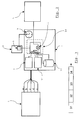
- a pay-TV system such as that of Fig. 1, is a typical example of a system in which reliable time validation is required.
- Each subscriber has a terminal 1 for receiving signals broadcast to it.
- the terminal 1 can be generic, i.e. suited for use in a number of different pay-TV systems.
- An owner of a terminal 1 can change his subscription or subscribe to several services without changing the terminal 1.
- some means for allowing use of the terminal 1 in the pay-TV system subscribed to are provided to the owner by the broadcasting organisation, for instance a code or a smart card for insertion into the terminal 1.
- the terminal 1 could also be specific to the broadcaster. In this case, it generally comes as part of the subscription. It could still be necessary to use a smart card with the terminal 1, depending on the particular pay-TV system used by the broadcaster.
- the terminal 1 in Fig. 1 is connected to a satellite dish 2.
- the terminal 1 is used to tune in to a carrier frequency and make information transmitted at this frequency available to a TV 3.
- the information is broadcast to the receiver from a broadcast station 4, via a satellite 6.
- the broadcast station 4 broadcasts information at a number of different carrier frequencies.
- the broadcast station 4 can broadcast information to the terminal 1, in digital or analogue form.
- the signal may be compressed or encrypted, to prevent its contents becoming accessible to non-subscribers.
- Fig. 1 shows a pay-TV system making use of satellite communication
- the invention is not restricted to broadcasts via satellite.
- Other pay-TV systems use networks of fibre-optic or electrically conducting cables.
- Pay-TV systems with terrestrial broadcasts, using antennae for transmitting and picking up the signal can also make use of the invention.
- a recorded signal e.g. from a video or DVD, can be played to the tuner.
- the video signal is used by the playback device, for instance the video recorder, which can then be regarded as the broadcast station 4, to generate a modulated signal having a carrier frequency.
- the terminal 1 comprises, or is attached to, the appropriate means for tuning to the carrier frequency and retrieving transmitted information.
- the broadcaster issues authorisation devices 6, like the smart card in Fig. 1.
- the information transmitted to the terminal 1 can be encrypted or compressed before transmission.
- the authorisation device 6 can then contain a key for enabling decompression or decryption by the terminal 1.
- a combination of encryption, compression and scrambling could also be envisaged, in which case the authorisation device 6 and terminal 1 must perform a number of processes to make the broadcast information available to the user.
- the terminal 1 comprises means 7, 7' for tuning to a carrier frequency.
- the terminal 1 can tune in to two different frequencies at any one time. This is symbolised by the two means 7,7', although they could be sub-circuits in one single tuning circuit.
- the broadcast station 4 broadcasts information to the terminal 1 at one or more carrier frequencies a-e. Again, how the transmission is achieved is immaterial, as long as the signals are used to generate modulated signals with defined carrier frequencies.
- Time stamps are transmitted with the information in which the user is interested.
- the information is linked to the time at which it was made available to the user of the terminal 1. Restriction of access to the information to a certain period of time is thereby made possible. In addition, recording and playback of the signal at a later time is prevented.
- the terminal 1 must retrieve the time stamps, which are also comprised in one or more modulated signals characterised by one of a number of available carrier frequencies a-e. Time-related access control is provided by the fact that only an authorised terminal 1 can tune in to the correct carrier frequency at the correct moment for retrieving a time stamp, as will be described hereinafter.
- the terminal 1 in the example of Fig. 2 can simultaneously tune to two different carrier frequencies, it is advantageous to distribute time stamps using at least three different carrier frequencies. If time stamps are not simultaneously transmitted on all carrier frequencies, but transmitted using differing carrier frequencies, repeated switches between carrier frequencies a-e by the terminal tuning means 7,7' will be necessary.
- the authorisation device 6, connected to the terminal 1, comprises a micro-controller 8 with associated memory, which selects the frequency to tune in to for retrieving a time stamp.
- the authorisation device 6 is provided with rules for selecting a frequency. These rules are kept secret. It is also possible to provide the device 6 with a random number generator, making it theoretically impossible to guess which of the carrier frequencies a-e will be chosen next.
- the terminal 1, or maybe the authorisation device 6, comprises a real-time clock 9.
- This clock 9 keeps time using the same format and reference time as the broadcaster uses for the time stamps.
- the first retrieved time stamp is used to start the clock 9 with the correct time.
- the purpose of the real-time clock 9 is to be able to allow the user of the terminal 1 access at certain times or during a certain interval of time. This depends on the conditions of the subscription, as set by the broadcaster.
- the time according to the real-time clock 9 is checked against the time at which access is allowed. In this way, someone who has paid to watch a TV-programme only once, cannot record the signal to play it back at a later time.
- the real-time clock 9 is not tampered with after it has been set, it is advantageous to regularly check it. This can easily be done using further retrieved time stamps. The time according to these time stamps is then compared with that according to the real-time clock 9. If the difference in time falls outside a certain time window, the terminal 1 is disabled. The time window allows for inaccuracies in the comparison and any inevitable time lags due to signal processing and transmission. Validation of the time according to the real-time clock 9 ensures that a viewer cannot set the clock 9 back to watch a recorded signal a second time.
- the terminal 1 comprises means 10 for allowing use of the terminal, which selectively make the information available to an authorised user.
- means 10 will, as a rule, be in the form of a micro-controller with associated memory.
- the terminal is completely shut down when the user has no authorisation and powered up, if the user is authorised.
- access to certain channels can be blocked or released depending on the results of the user authorisation process.
- the information from the broadcast station 4 can be encrypted, encoded, or scrambled.
- the means 10 for allowing use of the terminal then comprise modules for decrypting, decoding or descrambling the information when it has been determined that the user is authorised to access the information.
- the means 10 for allowing use of the terminal comprise a decryptor 11, using a key stored in the authorisation device 6. If the authorisation device 6 determines that use of the terminal 1 should be disabled, decryption stops. This can occur when the time interval allowed for use has elapsed, or when the system has been tampered with.
- Means for decrypting keys are provided by entitlement management messages, provided to the user at longer intervals.
- An entitlement management message can be valid for a certain period of time. Accordingly, it is advantageous to time stamp entitlement management messages, to ensure that they are only usable during a certain period, just as information is time-stamped to ensure that it is only accessible during a certain period.
- An embodiment of the present invention can easily comprise this feature, for example by adding the entitlement management message to the time stamp, or sending the message with the time-stamped broadcast information.
- the terminal 1 shown in Fig. 2 can simultaneously tune to two carrier frequencies. This can be used to advantage.
- One of the means 7,7' can be used to tune to the carrier frequency from which to retrieve a time stamp, whilst the other stays tuned to the carrier frequency at which the information is transmitted. This would prevent interruption in the delivery of the signal to the connected device 3 when the time stamp is not broadcast with the same carrier frequency as the information.
- the terminal 1 can have some kind of storage means 12 for storing demodulated signals before decryption, in order to prevent disruption of viewing during the short period of time needed for retrieving a time stamp.
- Fig. 3 shows an example of a time stamp with four fields.
- One data field contains the date 31, another contains the time 32. Of course, these two fields could be combined into one.
- a third data field contains the carrier identification 33, i.e. an indication of which carrier frequency is used to transmit this particular time stamp.
- the last field of the time stamp is an encrypted signature 34.
- the signature is specific for each carrier frequency. Decryption of the encrypted signature 34 gives information on one or all of the other data 31,32,33 in the signature. This is a protective measure against false time stamps, to further increase the reliability of the system. In cases where an entitlement message is included in the time stamp, it can be contained in a further field in the time stamp, not shown in Fig. 3.
- Fig. 4 shows an example of a process of time validation as carried out by the system.
- the authorisation device 6 selects a carrier frequency to tune in to for retrieving a time stamp. Ideally, this is done using a random number generator.
- a request for a time stamp is sent to the terminal 1, along with the carrier frequency to tune in to for retrieving this time stamp.
- the authorisation device 6 keeps track of the requested frequency, so that it can be checked against the carrier identification 33 and encrypted signature 34 comprised in the retrieved time stamp. These should, of course correspond, when the authorisation device 6 is authentic.
- the terminal 1 receives the request for a time stamp and the relevant carrier frequency to use to retrieve it.
- One of the tuning means 7,7' tunes in to the carrier frequency and the time stamp is retrieved.
- Either the time stamp is sent directly to the authorisation device 6, or the signature is first decrypted in the terminal 1, using a key supplied by the authorisation device 6.
- the decrypted signature 34 proves that the time stamp has indeed been retrieved from the signal with the requested carrier frequency.
- the time 32 can then be retrieved from the time stamp.
- the whole process can then be repeated to retrieve a second time stamp. Any time stamp that is not the first retrieved time stamp can be used to validate the time, i.e. check that the real-time clock 9 is still set to the correct time.
- the size of the difference between the time according to the real-time clock 9 and that according to the latest time stamp is determined. If this size is smaller than a certain permissible window, then the time is correct.
- the received information can be decrypted in the decryptor 11, and passed on to the device, for instance the TV 3, attached to the terminal 1. After a certain time delay, the process of time validation is repeated again.
Abstract
Description
- The invention relates to a system for time validation, comprising a terminal with means for tuning in to a number of different carrier frequencies, an authorisation device, e.g. a smart card, capable of communicating with the terminal and means to transmit time stamps, using a modulated signal having a carrier frequency, to the terminal. The invention also relates to a terminal and to an authorisation device in such a system. The invention further relates to a computer program for loading onto a programmable device e.g. a smart card, in order to use it as an authorisation device in such a system.
- When a user of the terminal in such a system is only privileged to make use of it at certain times, a representation of the current time in the terminal must be validated to check whether the current time is such a certain time. Some systems keep time using only the time stamps. Others can comprise a clock in the terminal in order to keep the time. The time according to clock and time stamps can be validated by checking the two values against each other.
- Existing systems for time validation are, however, generally not reliable. In order to keep the complexity and costs of such systems down, only the authorisation device is usually made secure against tampering. Terminals are usually of a standard type, not made to withstand hacking. A clock in the terminal could be set to a different time or perhaps slowed down or speeded up. Time stamps transmitted to the terminal can be recorded and played back later in a 'spoofing' attack.
- To obtain a system to reliably validate the time, the system according to the invention is characterised in that the authorisation device comprises means for selecting a carrier frequency to tune in to for retrieving a time stamp. It is thus impossible to provide a false time stamp to the terminal, since one would have to know beforehand at which carrier frequency to transmit it. Such knowledge can only be obtained from the authorisation device, which is secure.
- In a preferred embodiment of the system according to the present invention, time stamps are transmitted at a number of different carrier frequencies, which exceeds the number of carrier frequencies a terminal can simultaneously tune in to. This makes transmission of false time stamps at several different carrier frequencies infeasible.
- In another preferred embodiment of the system according to the present invention, each time stamp comprises a field identifying the carrier frequency, a field representing the date, a field representing the time, and an encrypted signature. This signature provides a further way for the smart card to verify that an authentic time stamp has been transmitted to the terminal.
- In an advantageous embodiment of the system according to the present invention, the authorisation device comprises means to randomly select a carrier frequency to tune in to for retrieving a time stamp. Thus, it is not even theoretically possible to predict beforehand, which carrier frequency will be selected to retrieve a time stamp.
- The invention will now be described in further detail with reference to the enclosed drawings of which
- Fig. 1 shows a schematic example of a pay-TV system with features of a system according to the present invention.
- Fig. 2 shows a schematic diagram of an embodiment of a system according to the present invention.
- Fig. 3 exemplifies a time stamp.
- Fig. 4 shows a flow diagram of a process carried out in a system according to the present invention.
- A pay-TV system, such as that of Fig. 1, is a typical example of a system in which reliable time validation is required. Each subscriber has a
terminal 1 for receiving signals broadcast to it. Theterminal 1 can be generic, i.e. suited for use in a number of different pay-TV systems. An owner of aterminal 1 can change his subscription or subscribe to several services without changing theterminal 1. In this case, some means for allowing use of theterminal 1 in the pay-TV system subscribed to are provided to the owner by the broadcasting organisation, for instance a code or a smart card for insertion into theterminal 1. Theterminal 1 could also be specific to the broadcaster. In this case, it generally comes as part of the subscription. It could still be necessary to use a smart card with theterminal 1, depending on the particular pay-TV system used by the broadcaster. - The
terminal 1 in Fig. 1 is connected to asatellite dish 2. Theterminal 1 is used to tune in to a carrier frequency and make information transmitted at this frequency available to aTV 3. The information is broadcast to the receiver from abroadcast station 4, via asatellite 6. Thebroadcast station 4 broadcasts information at a number of different carrier frequencies. Thebroadcast station 4 can broadcast information to theterminal 1, in digital or analogue form. The signal may be compressed or encrypted, to prevent its contents becoming accessible to non-subscribers. - Although Fig. 1 shows a pay-TV system making use of satellite communication, the invention is not restricted to broadcasts via satellite. Other pay-TV systems use networks of fibre-optic or electrically conducting cables. Pay-TV systems with terrestrial broadcasts, using antennae for transmitting and picking up the signal, can also make use of the invention. Additionally, a recorded signal, e.g. from a video or DVD, can be played to the tuner. In this case, the video signal is used by the playback device, for instance the video recorder, which can then be regarded as the
broadcast station 4, to generate a modulated signal having a carrier frequency. In each case, theterminal 1 comprises, or is attached to, the appropriate means for tuning to the carrier frequency and retrieving transmitted information. - To prevent someone with a
terminal 1 but no subscription from receiving the information, the broadcaster issuesauthorisation devices 6, like the smart card in Fig. 1. A device similar to a smart card, for instance a transponder key, could also be used. As mentioned above, the information transmitted to theterminal 1 can be encrypted or compressed before transmission. Theauthorisation device 6 can then contain a key for enabling decompression or decryption by theterminal 1. A combination of encryption, compression and scrambling could also be envisaged, in which case theauthorisation device 6 andterminal 1 must perform a number of processes to make the broadcast information available to the user. - To explain in more detail the various components of the system, reference is made to Fig. 2. Here, the
terminal 1 comprises means 7, 7' for tuning to a carrier frequency. In the shown embodiment, theterminal 1 can tune in to two different frequencies at any one time. This is symbolised by the two means 7,7', although they could be sub-circuits in one single tuning circuit. Thebroadcast station 4 broadcasts information to theterminal 1 at one or more carrier frequencies a-e. Again, how the transmission is achieved is immaterial, as long as the signals are used to generate modulated signals with defined carrier frequencies. - Time stamps are transmitted with the information in which the user is interested. Thus, the information is linked to the time at which it was made available to the user of the
terminal 1. Restriction of access to the information to a certain period of time is thereby made possible. In addition, recording and playback of the signal at a later time is prevented. Theterminal 1 must retrieve the time stamps, which are also comprised in one or more modulated signals characterised by one of a number of available carrier frequencies a-e. Time-related access control is provided by the fact that only an authorisedterminal 1 can tune in to the correct carrier frequency at the correct moment for retrieving a time stamp, as will be described hereinafter. - Since the
terminal 1 in the example of Fig. 2 can simultaneously tune to two different carrier frequencies, it is advantageous to distribute time stamps using at least three different carrier frequencies. If time stamps are not simultaneously transmitted on all carrier frequencies, but transmitted using differing carrier frequencies, repeated switches between carrier frequencies a-e by the terminal tuning means 7,7' will be necessary. - The
authorisation device 6, connected to theterminal 1, comprises amicro-controller 8 with associated memory, which selects the frequency to tune in to for retrieving a time stamp. Theauthorisation device 6 is provided with rules for selecting a frequency. These rules are kept secret. It is also possible to provide thedevice 6 with a random number generator, making it theoretically impossible to guess which of the carrier frequencies a-e will be chosen next. - The
terminal 1, or maybe theauthorisation device 6, comprises a real-time clock 9. Thisclock 9 keeps time using the same format and reference time as the broadcaster uses for the time stamps. The first retrieved time stamp is used to start theclock 9 with the correct time. The purpose of the real-time clock 9 is to be able to allow the user of theterminal 1 access at certain times or during a certain interval of time. This depends on the conditions of the subscription, as set by the broadcaster. The time according to the real-time clock 9 is checked against the time at which access is allowed. In this way, someone who has paid to watch a TV-programme only once, cannot record the signal to play it back at a later time. - To make sure the real-
time clock 9 is not tampered with after it has been set, it is advantageous to regularly check it. This can easily be done using further retrieved time stamps. The time according to these time stamps is then compared with that according to the real-time clock 9. If the difference in time falls outside a certain time window, theterminal 1 is disabled. The time window allows for inaccuracies in the comparison and any inevitable time lags due to signal processing and transmission. Validation of the time according to the real-time clock 9 ensures that a viewer cannot set theclock 9 back to watch a recorded signal a second time. - In the usual case when the user wants access to information comprised in one or more of the modulated signals having a carrier frequency, the
terminal 1 comprises means 10 for allowing use of the terminal, which selectively make the information available to an authorised user. These means 10 will, as a rule, be in the form of a micro-controller with associated memory. - Selective access to the information can be afforded by these
means 10 in a variety of ways, depending on the particular system. In a simple embodiment, the terminal is completely shut down when the user has no authorisation and powered up, if the user is authorised. Alternatively, access to certain channels can be blocked or released depending on the results of the user authorisation process. As another alternative, the information from thebroadcast station 4 can be encrypted, encoded, or scrambled. The means 10 for allowing use of the terminal then comprise modules for decrypting, decoding or descrambling the information when it has been determined that the user is authorised to access the information. - In the example of Fig. 2, the
means 10 for allowing use of the terminal comprise adecryptor 11, using a key stored in theauthorisation device 6. If theauthorisation device 6 determines that use of theterminal 1 should be disabled, decryption stops. This can occur when the time interval allowed for use has elapsed, or when the system has been tampered with. - It is advantageous to change the key for decrypting the information often. This can be done by sending new keys in encrypted form. Means for decrypting keys are provided by entitlement management messages, provided to the user at longer intervals. An entitlement management message can be valid for a certain period of time. Accordingly, it is advantageous to time stamp entitlement management messages, to ensure that they are only usable during a certain period, just as information is time-stamped to ensure that it is only accessible during a certain period. An embodiment of the present invention can easily comprise this feature, for example by adding the entitlement management message to the time stamp, or sending the message with the time-stamped broadcast information.
- The
terminal 1 shown in Fig. 2 can simultaneously tune to two carrier frequencies. This can be used to advantage. One of themeans 7,7' can be used to tune to the carrier frequency from which to retrieve a time stamp, whilst the other stays tuned to the carrier frequency at which the information is transmitted. This would prevent interruption in the delivery of the signal to theconnected device 3 when the time stamp is not broadcast with the same carrier frequency as the information. Alternatively, or additionally, theterminal 1 can have some kind of storage means 12 for storing demodulated signals before decryption, in order to prevent disruption of viewing during the short period of time needed for retrieving a time stamp. - Fig. 3 shows an example of a time stamp with four fields. One data field contains the
date 31, another contains thetime 32. Of course, these two fields could be combined into one. A third data field contains thecarrier identification 33, i.e. an indication of which carrier frequency is used to transmit this particular time stamp. The last field of the time stamp is anencrypted signature 34. The signature is specific for each carrier frequency. Decryption of theencrypted signature 34 gives information on one or all of theother data - To summarise the important aspects mentioned above, Fig. 4 shows an example of a process of time validation as carried out by the system. After the
terminal 1 has been switched on, theauthorisation device 6 selects a carrier frequency to tune in to for retrieving a time stamp. Ideally, this is done using a random number generator. A request for a time stamp is sent to theterminal 1, along with the carrier frequency to tune in to for retrieving this time stamp. Theauthorisation device 6 keeps track of the requested frequency, so that it can be checked against thecarrier identification 33 andencrypted signature 34 comprised in the retrieved time stamp. These should, of course correspond, when theauthorisation device 6 is authentic. - The
terminal 1 receives the request for a time stamp and the relevant carrier frequency to use to retrieve it. One of the tuning means 7,7' tunes in to the carrier frequency and the time stamp is retrieved. Either the time stamp is sent directly to theauthorisation device 6, or the signature is first decrypted in theterminal 1, using a key supplied by theauthorisation device 6. At any rate, the decryptedsignature 34 proves that the time stamp has indeed been retrieved from the signal with the requested carrier frequency. Thetime 32 can then be retrieved from the time stamp. - If this is the first retrieved time stamp, it is used to initialise the real-
time clock 9. The whole process can then be repeated to retrieve a second time stamp. Any time stamp that is not the first retrieved time stamp can be used to validate the time, i.e. check that the real-time clock 9 is still set to the correct time. The size of the difference between the time according to the real-time clock 9 and that according to the latest time stamp is determined. If this size is smaller than a certain permissible window, then the time is correct. Providing the user of theterminal 1 is authorised to receive the information at that moment in time, the received information can be decrypted in thedecryptor 11, and passed on to the device, for instance theTV 3, attached to theterminal 1. After a certain time delay, the process of time validation is repeated again. - It is clear that the invention is not limited to the above-described embodiments, given by way of example. The invention can be varied within the scope of the claims. Thus, all communication methods that allow the use of modulated signals having a carrier frequency can be used in the system according to the invention. Whether and, if so, what kind of information is transmitted with the time stamps is also irrelevant.
Claims (13)
- System for time validation, comprising
a terminal (1) with means (7,7') for tuning in to a number of different carrier frequencies (a-e), an authorisation device (6), e.g. a smart card, capable of communicating with the terminal (1) and means (2,5) to transmit time stamps, using a modulated signal having a carrier frequency, to the terminal (1), characterised in that the authorisation device (6) comprises means (9) for selecting a carrier frequency to tune in to for retrieving a time stamp. - System according to claim 1, wherein time stamps are transmitted at a number of different carrier frequencies (a-e), which exceeds the number of carrier frequencies a terminal (1) can simultaneously tune in to.
- System according to claim 1 or 2, wherein the time stamp comprises a field (33) identifying the carrier frequency, a field representing the date (31), a field representing the time (32), and an encrypted signature (34).
- System according to any one of claims 1-3, wherein the authorisation device (6) comprises means (8) to randomly select a carrier frequency to tune in to for retrieving a time stamp.
- System according to any one of claims 1-4, further comprising a real-time clock (9), with means to set the clock (9) to the time (32) retrieved from a time stamp.
- System according to claim 5, with means for repeatedly retrieving further time stamps and comparing the time (32) retrieved from at least one of the retrieved time stamps with the time according to the real-time clock (9).
- System according to claim 6, with means (10) for allowing use of the terminal (1), when the result of the comparison is smaller than a specified time window.
- System according to any one of the preceding claims, with means (10) for allowing use of the terminal (1) during a specified time interval.
- System according to any one of the preceding claims, with means to add information to the time stamps and insert both into at least one of the modulated signals having a carrier frequency.
- System according to any one of the preceding claims, further comprising a pay-TV broadcast station (4), with means for transmission at differing carrier frequencies to the terminal (1).
- Terminal (1) in a system according to any one of claims 1-10.
- Authorisation device (6), e.g. a smart card, in a system according to any one of claims 1-10.
- Computer program suitable for loading into a programmable device, e.g. a smart card, in order to use the programmable device, when programmed, as an authorisation device (6) in a system according to any one of claims 1-10.
Priority Applications (16)
| Application Number | Priority Date | Filing Date | Title |
|---|---|---|---|
| AT01202864T ATE377908T1 (en) | 2001-07-26 | 2001-07-26 | TIME VALIDATION SYSTEM |
| EP01202864A EP1280350B1 (en) | 2001-07-26 | 2001-07-26 | Time validation system |
| DE60131270T DE60131270T2 (en) | 2001-07-26 | 2001-07-26 | Time Valid reasoning system |
| ES01202864T ES2295105T3 (en) | 2001-07-26 | 2001-07-26 | SYSTEM FOR THE VALIDATION OF TIME TIME. |
| AU2002300190A AU2002300190B2 (en) | 2001-07-26 | 2002-07-19 | Time Validation System |
| ZA200205800A ZA200205800B (en) | 2001-07-26 | 2002-07-19 | Time validation system. |
| BR0202846-8A BR0202846A (en) | 2001-07-26 | 2002-07-24 | Time Validation System |
| MXPA02007244A MXPA02007244A (en) | 2001-07-26 | 2002-07-25 | Time validation system. |
| TW091116524A TWI222041B (en) | 2001-07-26 | 2002-07-25 | Time validation system |
| NZ520400A NZ520400A (en) | 2001-07-26 | 2002-07-25 | Validation system where the subscriber unit checks transmitted time stamps in selected carrier frequencies |
| CA2395026A CA2395026C (en) | 2001-07-26 | 2002-07-25 | Time validation system |
| CNB021269637A CN1232121C (en) | 2001-07-26 | 2002-07-25 | Time verifying system |
| US10/206,245 US7296162B2 (en) | 2001-07-26 | 2002-07-26 | Time validation system |
| JP2002217845A JP4216534B2 (en) | 2001-07-26 | 2002-07-26 | Time verification system |
| HK03101208.3A HK1049088B (en) | 2001-07-26 | 2003-02-18 | Time validation system |
| CY20081100106T CY1107162T1 (en) | 2001-07-26 | 2008-01-31 | TIME VALIDATION SYSTEM |
Applications Claiming Priority (1)
| Application Number | Priority Date | Filing Date | Title |
|---|---|---|---|
| EP01202864A EP1280350B1 (en) | 2001-07-26 | 2001-07-26 | Time validation system |
Publications (2)
| Publication Number | Publication Date |
|---|---|
| EP1280350A1 true EP1280350A1 (en) | 2003-01-29 |
| EP1280350B1 EP1280350B1 (en) | 2007-11-07 |
Family
ID=8180714
Family Applications (1)
| Application Number | Title | Priority Date | Filing Date |
|---|---|---|---|
| EP01202864A Expired - Lifetime EP1280350B1 (en) | 2001-07-26 | 2001-07-26 | Time validation system |
Country Status (16)
| Country | Link |
|---|---|
| US (1) | US7296162B2 (en) |
| EP (1) | EP1280350B1 (en) |
| JP (1) | JP4216534B2 (en) |
| CN (1) | CN1232121C (en) |
| AT (1) | ATE377908T1 (en) |
| AU (1) | AU2002300190B2 (en) |
| BR (1) | BR0202846A (en) |
| CA (1) | CA2395026C (en) |
| CY (1) | CY1107162T1 (en) |
| DE (1) | DE60131270T2 (en) |
| ES (1) | ES2295105T3 (en) |
| HK (1) | HK1049088B (en) |
| MX (1) | MXPA02007244A (en) |
| NZ (1) | NZ520400A (en) |
| TW (1) | TWI222041B (en) |
| ZA (1) | ZA200205800B (en) |
Cited By (73)
| Publication number | Priority date | Publication date | Assignee | Title |
|---|---|---|---|---|
| EP1808017A1 (en) * | 2004-11-01 | 2007-07-18 | NDS Limited | Efficient and secure renewal of entitlements |
| CN101364978B (en) * | 2007-08-10 | 2011-06-22 | 鸿富锦精密工业(深圳)有限公司 | Instant time clock precise verification system and method |
| US7967216B2 (en) | 2008-05-22 | 2011-06-28 | Murata Manufacturing Co., Ltd. | Wireless IC device |
| US8011589B2 (en) | 2008-06-25 | 2011-09-06 | Murata Manufacturing Co., Ltd. | Wireless IC device and manufacturing method thereof |
| US8177138B2 (en) | 2008-10-29 | 2012-05-15 | Murata Manufacturing Co., Ltd. | Radio IC device |
| US8191791B2 (en) | 2007-07-17 | 2012-06-05 | Murata Manufacturing Co., Ltd. | Wireless IC device and electronic apparatus |
| US8228765B2 (en) | 2006-06-30 | 2012-07-24 | Murata Manufacturing Co., Ltd. | Optical disc |
| US8299929B2 (en) | 2006-09-26 | 2012-10-30 | Murata Manufacturing Co., Ltd. | Inductively coupled module and item with inductively coupled module |
| US8336786B2 (en) | 2010-03-12 | 2012-12-25 | Murata Manufacturing Co., Ltd. | Wireless communication device and metal article |
| US8342416B2 (en) | 2009-01-09 | 2013-01-01 | Murata Manufacturing Co., Ltd. | Wireless IC device, wireless IC module and method of manufacturing wireless IC module |
| US8360330B2 (en) | 2007-12-26 | 2013-01-29 | Murata Manufacturing Co., Ltd. | Antenna device and radio frequency IC device |
| US8381997B2 (en) | 2009-06-03 | 2013-02-26 | Murata Manufacturing Co., Ltd. | Radio frequency IC device and method of manufacturing the same |
| US8400365B2 (en) | 2009-11-20 | 2013-03-19 | Murata Manufacturing Co., Ltd. | Antenna device and mobile communication terminal |
| US8400307B2 (en) | 2007-07-18 | 2013-03-19 | Murata Manufacturing Co., Ltd. | Radio frequency IC device and electronic apparatus |
| US8418928B2 (en) | 2009-04-14 | 2013-04-16 | Murata Manufacturing Co., Ltd. | Wireless IC device component and wireless IC device |
| US8424769B2 (en) | 2010-07-08 | 2013-04-23 | Murata Manufacturing Co., Ltd. | Antenna and RFID device |
| US8424762B2 (en) | 2007-04-14 | 2013-04-23 | Murata Manufacturing Co., Ltd. | Wireless IC device and component for wireless IC device |
| US8531346B2 (en) | 2007-04-26 | 2013-09-10 | Murata Manufacturing Co., Ltd. | Wireless IC device |
| US8546927B2 (en) | 2010-09-03 | 2013-10-01 | Murata Manufacturing Co., Ltd. | RFIC chip mounting structure |
| US8552870B2 (en) | 2007-07-09 | 2013-10-08 | Murata Manufacturing Co., Ltd. | Wireless IC device |
| US8583043B2 (en) | 2009-01-16 | 2013-11-12 | Murata Manufacturing Co., Ltd. | High-frequency device and wireless IC device |
| US8590797B2 (en) | 2008-05-21 | 2013-11-26 | Murata Manufacturing Co., Ltd. | Wireless IC device |
| US8596545B2 (en) | 2008-05-28 | 2013-12-03 | Murata Manufacturing Co., Ltd. | Component of wireless IC device and wireless IC device |
| US8602310B2 (en) | 2010-03-03 | 2013-12-10 | Murata Manufacturing Co., Ltd. | Radio communication device and radio communication terminal |
| US8610636B2 (en) | 2007-12-20 | 2013-12-17 | Murata Manufacturing Co., Ltd. | Radio frequency IC device |
| US8613395B2 (en) | 2011-02-28 | 2013-12-24 | Murata Manufacturing Co., Ltd. | Wireless communication device |
| US8676117B2 (en) | 2006-01-19 | 2014-03-18 | Murata Manufacturing Co., Ltd. | Wireless IC device and component for wireless IC device |
| US8680971B2 (en) | 2009-09-28 | 2014-03-25 | Murata Manufacturing Co., Ltd. | Wireless IC device and method of detecting environmental state using the device |
| US8692718B2 (en) | 2008-11-17 | 2014-04-08 | Murata Manufacturing Co., Ltd. | Antenna and wireless IC device |
| US8718727B2 (en) | 2009-12-24 | 2014-05-06 | Murata Manufacturing Co., Ltd. | Antenna having structure for multi-angled reception and mobile terminal including the antenna |
| US8720789B2 (en) | 2012-01-30 | 2014-05-13 | Murata Manufacturing Co., Ltd. | Wireless IC device |
| US8740093B2 (en) | 2011-04-13 | 2014-06-03 | Murata Manufacturing Co., Ltd. | Radio IC device and radio communication terminal |
| US8757500B2 (en) | 2007-05-11 | 2014-06-24 | Murata Manufacturing Co., Ltd. | Wireless IC device |
| US8770489B2 (en) | 2011-07-15 | 2014-07-08 | Murata Manufacturing Co., Ltd. | Radio communication device |
| US8797225B2 (en) | 2011-03-08 | 2014-08-05 | Murata Manufacturing Co., Ltd. | Antenna device and communication terminal apparatus |
| US8797148B2 (en) | 2008-03-03 | 2014-08-05 | Murata Manufacturing Co., Ltd. | Radio frequency IC device and radio communication system |
| US8810456B2 (en) | 2009-06-19 | 2014-08-19 | Murata Manufacturing Co., Ltd. | Wireless IC device and coupling method for power feeding circuit and radiation plate |
| US8814056B2 (en) | 2011-07-19 | 2014-08-26 | Murata Manufacturing Co., Ltd. | Antenna device, RFID tag, and communication terminal apparatus |
| US8847831B2 (en) | 2009-07-03 | 2014-09-30 | Murata Manufacturing Co., Ltd. | Antenna and antenna module |
| US8853549B2 (en) | 2009-09-30 | 2014-10-07 | Murata Manufacturing Co., Ltd. | Circuit substrate and method of manufacturing same |
| US8870077B2 (en) | 2008-08-19 | 2014-10-28 | Murata Manufacturing Co., Ltd. | Wireless IC device and method for manufacturing same |
| US8878739B2 (en) | 2011-07-14 | 2014-11-04 | Murata Manufacturing Co., Ltd. | Wireless communication device |
| US8905296B2 (en) | 2011-12-01 | 2014-12-09 | Murata Manufacturing Co., Ltd. | Wireless integrated circuit device and method of manufacturing the same |
| US8905316B2 (en) | 2010-05-14 | 2014-12-09 | Murata Manufacturing Co., Ltd. | Wireless IC device |
| US8937576B2 (en) | 2011-04-05 | 2015-01-20 | Murata Manufacturing Co., Ltd. | Wireless communication device |
| US8944335B2 (en) | 2010-09-30 | 2015-02-03 | Murata Manufacturing Co., Ltd. | Wireless IC device |
| US8976075B2 (en) | 2009-04-21 | 2015-03-10 | Murata Manufacturing Co., Ltd. | Antenna device and method of setting resonant frequency of antenna device |
| US8981906B2 (en) | 2010-08-10 | 2015-03-17 | Murata Manufacturing Co., Ltd. | Printed wiring board and wireless communication system |
| US8991713B2 (en) | 2011-01-14 | 2015-03-31 | Murata Manufacturing Co., Ltd. | RFID chip package and RFID tag |
| US9024837B2 (en) | 2010-03-31 | 2015-05-05 | Murata Manufacturing Co., Ltd. | Antenna and wireless communication device |
| US9024725B2 (en) | 2009-11-04 | 2015-05-05 | Murata Manufacturing Co., Ltd. | Communication terminal and information processing system |
| US9077067B2 (en) | 2008-07-04 | 2015-07-07 | Murata Manufacturing Co., Ltd. | Radio IC device |
| US9104950B2 (en) | 2009-01-30 | 2015-08-11 | Murata Manufacturing Co., Ltd. | Antenna and wireless IC device |
| US9117157B2 (en) | 2009-10-02 | 2015-08-25 | Murata Manufacturing Co., Ltd. | Wireless IC device and electromagnetic coupling module |
| US9123996B2 (en) | 2010-05-14 | 2015-09-01 | Murata Manufacturing Co., Ltd. | Wireless IC device |
| US9165239B2 (en) | 2006-04-26 | 2015-10-20 | Murata Manufacturing Co., Ltd. | Electromagnetic-coupling-module-attached article |
| US9166291B2 (en) | 2010-10-12 | 2015-10-20 | Murata Manufacturing Co., Ltd. | Antenna device and communication terminal apparatus |
| US9178279B2 (en) | 2009-11-04 | 2015-11-03 | Murata Manufacturing Co., Ltd. | Wireless IC tag, reader-writer, and information processing system |
| US9231305B2 (en) | 2008-10-24 | 2016-01-05 | Murata Manufacturing Co., Ltd. | Wireless IC device |
| US9236651B2 (en) | 2010-10-21 | 2016-01-12 | Murata Manufacturing Co., Ltd. | Communication terminal device |
| US9281873B2 (en) | 2008-05-26 | 2016-03-08 | Murata Manufacturing Co., Ltd. | Wireless IC device system and method of determining authenticity of wireless IC device |
| US9378452B2 (en) | 2011-05-16 | 2016-06-28 | Murata Manufacturing Co., Ltd. | Radio IC device |
| US9444143B2 (en) | 2009-10-16 | 2016-09-13 | Murata Manufacturing Co., Ltd. | Antenna and wireless IC device |
| US9460320B2 (en) | 2009-10-27 | 2016-10-04 | Murata Manufacturing Co., Ltd. | Transceiver and radio frequency identification tag reader |
| US9460376B2 (en) | 2007-07-18 | 2016-10-04 | Murata Manufacturing Co., Ltd. | Radio IC device |
| US9461363B2 (en) | 2009-11-04 | 2016-10-04 | Murata Manufacturing Co., Ltd. | Communication terminal and information processing system |
| US9543642B2 (en) | 2011-09-09 | 2017-01-10 | Murata Manufacturing Co., Ltd. | Antenna device and wireless device |
| US9558384B2 (en) | 2010-07-28 | 2017-01-31 | Murata Manufacturing Co., Ltd. | Antenna apparatus and communication terminal instrument |
| US9692128B2 (en) | 2012-02-24 | 2017-06-27 | Murata Manufacturing Co., Ltd. | Antenna device and wireless communication device |
| US9727765B2 (en) | 2010-03-24 | 2017-08-08 | Murata Manufacturing Co., Ltd. | RFID system including a reader/writer and RFID tag |
| US9761923B2 (en) | 2011-01-05 | 2017-09-12 | Murata Manufacturing Co., Ltd. | Wireless communication device |
| US10013650B2 (en) | 2010-03-03 | 2018-07-03 | Murata Manufacturing Co., Ltd. | Wireless communication module and wireless communication device |
| US10235544B2 (en) | 2012-04-13 | 2019-03-19 | Murata Manufacturing Co., Ltd. | Inspection method and inspection device for RFID tag |
Families Citing this family (12)
| Publication number | Priority date | Publication date | Assignee | Title |
|---|---|---|---|---|
| FI118309B (en) * | 2003-12-29 | 2007-09-28 | Innoka Oy | Procedure and arrangement for real-time tipping with offline terminal |
| US7979731B2 (en) * | 2004-07-15 | 2011-07-12 | Panasonic Corporation | Time authentication device, time authentication method, computer program, recording medium, integrated circuit, and time authentication system |
| EP1819067B1 (en) * | 2006-02-08 | 2011-09-14 | Alcatel Lucent | Method of synchronizing transmissions to users in a hybrid telecommunications network |
| US20070223392A1 (en) * | 2006-03-21 | 2007-09-27 | Samsung Electronics Co., Ltd. | Method and device for checking validity period of certificate and method and device for displaying content information |
| US8051488B2 (en) * | 2006-10-05 | 2011-11-01 | Microsoft Corporation | Trial usage for encrypted subscription-based data |
| EP2068565A1 (en) * | 2007-12-07 | 2009-06-10 | Gemplus | Subscriber identity module and associated distribution server, adapted to manage programs with an indeterminate duration |
| US8117449B2 (en) * | 2007-12-27 | 2012-02-14 | Mastercard International, Inc. | Method to detect man-in-the-middle (MITM) or relay attacks |
| KR101528856B1 (en) * | 2008-08-14 | 2015-06-15 | 삼성전자주식회사 | Contents receiving apparatus obtaining application control information and method thereof |
| JP4661922B2 (en) | 2008-09-03 | 2011-03-30 | ソニー株式会社 | Image processing apparatus, imaging apparatus, solid-state imaging device, image processing method, and program |
| TWI450552B (en) * | 2009-01-14 | 2014-08-21 | Chunghwa Telecom Co Ltd | Traceability precision timestamp security system |
| KR101673598B1 (en) * | 2010-03-12 | 2016-11-22 | 삼성전자주식회사 | Method and apparatus for reporting audience measurement in content transmission system |
| EP2405650A1 (en) * | 2010-07-09 | 2012-01-11 | Nagravision S.A. | A method for secure transfer of messages |
Citations (5)
| Publication number | Priority date | Publication date | Assignee | Title |
|---|---|---|---|---|
| EP0666694A1 (en) * | 1994-02-02 | 1995-08-09 | General Instrument Corporation Of Delaware | Method and apparatus for controlling access to digital signals |
| US5500897A (en) * | 1993-07-22 | 1996-03-19 | International Business Machines Corporation | Client/server based secure timekeeping system |
| WO1997028649A1 (en) * | 1996-01-30 | 1997-08-07 | Oy Nokia Ab | Scrambling of digital media objects in connection with transmission and storage |
| EP0898425A2 (en) * | 1997-08-15 | 1999-02-24 | Lucent Technologies Inc. | Cryptographic method and apparatus for restricting access to transmitted programming content using extended headers |
| US6154206A (en) * | 1998-05-06 | 2000-11-28 | Sony Corporation Of Japan | Method and apparatus for distributed conditional access control on a serial communication network |
Family Cites Families (1)
| Publication number | Priority date | Publication date | Assignee | Title |
|---|---|---|---|---|
| US5572514A (en) * | 1993-06-30 | 1996-11-05 | Casio Computer Co., Ltd. | Spread spectrum communication system capable of detecting occupying state of channel by off-communication terminal |
-
2001
- 2001-07-26 DE DE60131270T patent/DE60131270T2/en not_active Expired - Lifetime
- 2001-07-26 ES ES01202864T patent/ES2295105T3/en not_active Expired - Lifetime
- 2001-07-26 EP EP01202864A patent/EP1280350B1/en not_active Expired - Lifetime
- 2001-07-26 AT AT01202864T patent/ATE377908T1/en not_active IP Right Cessation
-
2002
- 2002-07-19 AU AU2002300190A patent/AU2002300190B2/en not_active Ceased
- 2002-07-19 ZA ZA200205800A patent/ZA200205800B/en unknown
- 2002-07-24 BR BR0202846-8A patent/BR0202846A/en not_active IP Right Cessation
- 2002-07-25 CN CNB021269637A patent/CN1232121C/en not_active Expired - Fee Related
- 2002-07-25 CA CA2395026A patent/CA2395026C/en not_active Expired - Fee Related
- 2002-07-25 MX MXPA02007244A patent/MXPA02007244A/en active IP Right Grant
- 2002-07-25 NZ NZ520400A patent/NZ520400A/en unknown
- 2002-07-25 TW TW091116524A patent/TWI222041B/en not_active IP Right Cessation
- 2002-07-26 JP JP2002217845A patent/JP4216534B2/en not_active Expired - Fee Related
- 2002-07-26 US US10/206,245 patent/US7296162B2/en not_active Expired - Fee Related
-
2003
- 2003-02-18 HK HK03101208.3A patent/HK1049088B/en not_active IP Right Cessation
-
2008
- 2008-01-31 CY CY20081100106T patent/CY1107162T1/en unknown
Patent Citations (5)
| Publication number | Priority date | Publication date | Assignee | Title |
|---|---|---|---|---|
| US5500897A (en) * | 1993-07-22 | 1996-03-19 | International Business Machines Corporation | Client/server based secure timekeeping system |
| EP0666694A1 (en) * | 1994-02-02 | 1995-08-09 | General Instrument Corporation Of Delaware | Method and apparatus for controlling access to digital signals |
| WO1997028649A1 (en) * | 1996-01-30 | 1997-08-07 | Oy Nokia Ab | Scrambling of digital media objects in connection with transmission and storage |
| EP0898425A2 (en) * | 1997-08-15 | 1999-02-24 | Lucent Technologies Inc. | Cryptographic method and apparatus for restricting access to transmitted programming content using extended headers |
| US6154206A (en) * | 1998-05-06 | 2000-11-28 | Sony Corporation Of Japan | Method and apparatus for distributed conditional access control on a serial communication network |
Cited By (93)
| Publication number | Priority date | Publication date | Assignee | Title |
|---|---|---|---|---|
| EP1808017A4 (en) * | 2004-11-01 | 2008-10-15 | Nds Ltd | Efficient and secure renewal of entitlements |
| US8677462B2 (en) | 2004-11-01 | 2014-03-18 | Cisco Technology Inc. | Efficient and secure renewal of entitlements |
| EP1808017A1 (en) * | 2004-11-01 | 2007-07-18 | NDS Limited | Efficient and secure renewal of entitlements |
| US8676117B2 (en) | 2006-01-19 | 2014-03-18 | Murata Manufacturing Co., Ltd. | Wireless IC device and component for wireless IC device |
| US8725071B2 (en) | 2006-01-19 | 2014-05-13 | Murata Manufacturing Co., Ltd. | Wireless IC device and component for wireless IC device |
| US9165239B2 (en) | 2006-04-26 | 2015-10-20 | Murata Manufacturing Co., Ltd. | Electromagnetic-coupling-module-attached article |
| US8228765B2 (en) | 2006-06-30 | 2012-07-24 | Murata Manufacturing Co., Ltd. | Optical disc |
| US8299929B2 (en) | 2006-09-26 | 2012-10-30 | Murata Manufacturing Co., Ltd. | Inductively coupled module and item with inductively coupled module |
| US8424762B2 (en) | 2007-04-14 | 2013-04-23 | Murata Manufacturing Co., Ltd. | Wireless IC device and component for wireless IC device |
| US8531346B2 (en) | 2007-04-26 | 2013-09-10 | Murata Manufacturing Co., Ltd. | Wireless IC device |
| US8757500B2 (en) | 2007-05-11 | 2014-06-24 | Murata Manufacturing Co., Ltd. | Wireless IC device |
| US8662403B2 (en) | 2007-07-04 | 2014-03-04 | Murata Manufacturing Co., Ltd. | Wireless IC device and component for wireless IC device |
| US8552870B2 (en) | 2007-07-09 | 2013-10-08 | Murata Manufacturing Co., Ltd. | Wireless IC device |
| US8191791B2 (en) | 2007-07-17 | 2012-06-05 | Murata Manufacturing Co., Ltd. | Wireless IC device and electronic apparatus |
| US8413907B2 (en) | 2007-07-17 | 2013-04-09 | Murata Manufacturing Co., Ltd. | Wireless IC device and electronic apparatus |
| US9830552B2 (en) | 2007-07-18 | 2017-11-28 | Murata Manufacturing Co., Ltd. | Radio IC device |
| US8400307B2 (en) | 2007-07-18 | 2013-03-19 | Murata Manufacturing Co., Ltd. | Radio frequency IC device and electronic apparatus |
| US9460376B2 (en) | 2007-07-18 | 2016-10-04 | Murata Manufacturing Co., Ltd. | Radio IC device |
| CN101364978B (en) * | 2007-08-10 | 2011-06-22 | 鸿富锦精密工业(深圳)有限公司 | Instant time clock precise verification system and method |
| US8610636B2 (en) | 2007-12-20 | 2013-12-17 | Murata Manufacturing Co., Ltd. | Radio frequency IC device |
| US8360330B2 (en) | 2007-12-26 | 2013-01-29 | Murata Manufacturing Co., Ltd. | Antenna device and radio frequency IC device |
| US8915448B2 (en) | 2007-12-26 | 2014-12-23 | Murata Manufacturing Co., Ltd. | Antenna device and radio frequency IC device |
| US8797148B2 (en) | 2008-03-03 | 2014-08-05 | Murata Manufacturing Co., Ltd. | Radio frequency IC device and radio communication system |
| US9022295B2 (en) | 2008-05-21 | 2015-05-05 | Murata Manufacturing Co., Ltd. | Wireless IC device |
| US8590797B2 (en) | 2008-05-21 | 2013-11-26 | Murata Manufacturing Co., Ltd. | Wireless IC device |
| US8973841B2 (en) | 2008-05-21 | 2015-03-10 | Murata Manufacturing Co., Ltd. | Wireless IC device |
| US8047445B2 (en) | 2008-05-22 | 2011-11-01 | Murata Manufacturing Co., Ltd. | Wireless IC device and method of manufacturing the same |
| US7967216B2 (en) | 2008-05-22 | 2011-06-28 | Murata Manufacturing Co., Ltd. | Wireless IC device |
| US9281873B2 (en) | 2008-05-26 | 2016-03-08 | Murata Manufacturing Co., Ltd. | Wireless IC device system and method of determining authenticity of wireless IC device |
| US8596545B2 (en) | 2008-05-28 | 2013-12-03 | Murata Manufacturing Co., Ltd. | Component of wireless IC device and wireless IC device |
| US8011589B2 (en) | 2008-06-25 | 2011-09-06 | Murata Manufacturing Co., Ltd. | Wireless IC device and manufacturing method thereof |
| US9077067B2 (en) | 2008-07-04 | 2015-07-07 | Murata Manufacturing Co., Ltd. | Radio IC device |
| US8870077B2 (en) | 2008-08-19 | 2014-10-28 | Murata Manufacturing Co., Ltd. | Wireless IC device and method for manufacturing same |
| US9231305B2 (en) | 2008-10-24 | 2016-01-05 | Murata Manufacturing Co., Ltd. | Wireless IC device |
| US8177138B2 (en) | 2008-10-29 | 2012-05-15 | Murata Manufacturing Co., Ltd. | Radio IC device |
| US8692718B2 (en) | 2008-11-17 | 2014-04-08 | Murata Manufacturing Co., Ltd. | Antenna and wireless IC device |
| US8917211B2 (en) | 2008-11-17 | 2014-12-23 | Murata Manufacturing Co., Ltd. | Antenna and wireless IC device |
| US8342416B2 (en) | 2009-01-09 | 2013-01-01 | Murata Manufacturing Co., Ltd. | Wireless IC device, wireless IC module and method of manufacturing wireless IC module |
| US8544759B2 (en) | 2009-01-09 | 2013-10-01 | Murata Manufacturing., Ltd. | Wireless IC device, wireless IC module and method of manufacturing wireless IC module |
| US8583043B2 (en) | 2009-01-16 | 2013-11-12 | Murata Manufacturing Co., Ltd. | High-frequency device and wireless IC device |
| US9104950B2 (en) | 2009-01-30 | 2015-08-11 | Murata Manufacturing Co., Ltd. | Antenna and wireless IC device |
| US8876010B2 (en) | 2009-04-14 | 2014-11-04 | Murata Manufacturing Co., Ltd | Wireless IC device component and wireless IC device |
| US8418928B2 (en) | 2009-04-14 | 2013-04-16 | Murata Manufacturing Co., Ltd. | Wireless IC device component and wireless IC device |
| US8690070B2 (en) | 2009-04-14 | 2014-04-08 | Murata Manufacturing Co., Ltd. | Wireless IC device component and wireless IC device |
| US8976075B2 (en) | 2009-04-21 | 2015-03-10 | Murata Manufacturing Co., Ltd. | Antenna device and method of setting resonant frequency of antenna device |
| US9203157B2 (en) | 2009-04-21 | 2015-12-01 | Murata Manufacturing Co., Ltd. | Antenna device and method of setting resonant frequency of antenna device |
| US9564678B2 (en) | 2009-04-21 | 2017-02-07 | Murata Manufacturing Co., Ltd. | Antenna device and method of setting resonant frequency of antenna device |
| US8381997B2 (en) | 2009-06-03 | 2013-02-26 | Murata Manufacturing Co., Ltd. | Radio frequency IC device and method of manufacturing the same |
| US8810456B2 (en) | 2009-06-19 | 2014-08-19 | Murata Manufacturing Co., Ltd. | Wireless IC device and coupling method for power feeding circuit and radiation plate |
| US8847831B2 (en) | 2009-07-03 | 2014-09-30 | Murata Manufacturing Co., Ltd. | Antenna and antenna module |
| US8680971B2 (en) | 2009-09-28 | 2014-03-25 | Murata Manufacturing Co., Ltd. | Wireless IC device and method of detecting environmental state using the device |
| US8853549B2 (en) | 2009-09-30 | 2014-10-07 | Murata Manufacturing Co., Ltd. | Circuit substrate and method of manufacturing same |
| US9117157B2 (en) | 2009-10-02 | 2015-08-25 | Murata Manufacturing Co., Ltd. | Wireless IC device and electromagnetic coupling module |
| US9444143B2 (en) | 2009-10-16 | 2016-09-13 | Murata Manufacturing Co., Ltd. | Antenna and wireless IC device |
| US9460320B2 (en) | 2009-10-27 | 2016-10-04 | Murata Manufacturing Co., Ltd. | Transceiver and radio frequency identification tag reader |
| US9178279B2 (en) | 2009-11-04 | 2015-11-03 | Murata Manufacturing Co., Ltd. | Wireless IC tag, reader-writer, and information processing system |
| US9024725B2 (en) | 2009-11-04 | 2015-05-05 | Murata Manufacturing Co., Ltd. | Communication terminal and information processing system |
| US9461363B2 (en) | 2009-11-04 | 2016-10-04 | Murata Manufacturing Co., Ltd. | Communication terminal and information processing system |
| US8704716B2 (en) | 2009-11-20 | 2014-04-22 | Murata Manufacturing Co., Ltd. | Antenna device and mobile communication terminal |
| US8400365B2 (en) | 2009-11-20 | 2013-03-19 | Murata Manufacturing Co., Ltd. | Antenna device and mobile communication terminal |
| US8718727B2 (en) | 2009-12-24 | 2014-05-06 | Murata Manufacturing Co., Ltd. | Antenna having structure for multi-angled reception and mobile terminal including the antenna |
| US10013650B2 (en) | 2010-03-03 | 2018-07-03 | Murata Manufacturing Co., Ltd. | Wireless communication module and wireless communication device |
| US8602310B2 (en) | 2010-03-03 | 2013-12-10 | Murata Manufacturing Co., Ltd. | Radio communication device and radio communication terminal |
| US8336786B2 (en) | 2010-03-12 | 2012-12-25 | Murata Manufacturing Co., Ltd. | Wireless communication device and metal article |
| US8528829B2 (en) | 2010-03-12 | 2013-09-10 | Murata Manufacturing Co., Ltd. | Wireless communication device and metal article |
| US9727765B2 (en) | 2010-03-24 | 2017-08-08 | Murata Manufacturing Co., Ltd. | RFID system including a reader/writer and RFID tag |
| US9024837B2 (en) | 2010-03-31 | 2015-05-05 | Murata Manufacturing Co., Ltd. | Antenna and wireless communication device |
| US9123996B2 (en) | 2010-05-14 | 2015-09-01 | Murata Manufacturing Co., Ltd. | Wireless IC device |
| US8905316B2 (en) | 2010-05-14 | 2014-12-09 | Murata Manufacturing Co., Ltd. | Wireless IC device |
| US8424769B2 (en) | 2010-07-08 | 2013-04-23 | Murata Manufacturing Co., Ltd. | Antenna and RFID device |
| US9558384B2 (en) | 2010-07-28 | 2017-01-31 | Murata Manufacturing Co., Ltd. | Antenna apparatus and communication terminal instrument |
| US8981906B2 (en) | 2010-08-10 | 2015-03-17 | Murata Manufacturing Co., Ltd. | Printed wiring board and wireless communication system |
| US8546927B2 (en) | 2010-09-03 | 2013-10-01 | Murata Manufacturing Co., Ltd. | RFIC chip mounting structure |
| US8944335B2 (en) | 2010-09-30 | 2015-02-03 | Murata Manufacturing Co., Ltd. | Wireless IC device |
| US9166291B2 (en) | 2010-10-12 | 2015-10-20 | Murata Manufacturing Co., Ltd. | Antenna device and communication terminal apparatus |
| US9236651B2 (en) | 2010-10-21 | 2016-01-12 | Murata Manufacturing Co., Ltd. | Communication terminal device |
| US9761923B2 (en) | 2011-01-05 | 2017-09-12 | Murata Manufacturing Co., Ltd. | Wireless communication device |
| US8991713B2 (en) | 2011-01-14 | 2015-03-31 | Murata Manufacturing Co., Ltd. | RFID chip package and RFID tag |
| US8613395B2 (en) | 2011-02-28 | 2013-12-24 | Murata Manufacturing Co., Ltd. | Wireless communication device |
| US8757502B2 (en) | 2011-02-28 | 2014-06-24 | Murata Manufacturing Co., Ltd. | Wireless communication device |
| US8960561B2 (en) | 2011-02-28 | 2015-02-24 | Murata Manufacturing Co., Ltd. | Wireless communication device |
| US8797225B2 (en) | 2011-03-08 | 2014-08-05 | Murata Manufacturing Co., Ltd. | Antenna device and communication terminal apparatus |
| US8937576B2 (en) | 2011-04-05 | 2015-01-20 | Murata Manufacturing Co., Ltd. | Wireless communication device |
| US8740093B2 (en) | 2011-04-13 | 2014-06-03 | Murata Manufacturing Co., Ltd. | Radio IC device and radio communication terminal |
| US9378452B2 (en) | 2011-05-16 | 2016-06-28 | Murata Manufacturing Co., Ltd. | Radio IC device |
| US8878739B2 (en) | 2011-07-14 | 2014-11-04 | Murata Manufacturing Co., Ltd. | Wireless communication device |
| US8770489B2 (en) | 2011-07-15 | 2014-07-08 | Murata Manufacturing Co., Ltd. | Radio communication device |
| US8814056B2 (en) | 2011-07-19 | 2014-08-26 | Murata Manufacturing Co., Ltd. | Antenna device, RFID tag, and communication terminal apparatus |
| US9543642B2 (en) | 2011-09-09 | 2017-01-10 | Murata Manufacturing Co., Ltd. | Antenna device and wireless device |
| US8905296B2 (en) | 2011-12-01 | 2014-12-09 | Murata Manufacturing Co., Ltd. | Wireless integrated circuit device and method of manufacturing the same |
| US8720789B2 (en) | 2012-01-30 | 2014-05-13 | Murata Manufacturing Co., Ltd. | Wireless IC device |
| US9692128B2 (en) | 2012-02-24 | 2017-06-27 | Murata Manufacturing Co., Ltd. | Antenna device and wireless communication device |
| US10235544B2 (en) | 2012-04-13 | 2019-03-19 | Murata Manufacturing Co., Ltd. | Inspection method and inspection device for RFID tag |
Also Published As
| Publication number | Publication date |
|---|---|
| AU2002300190B2 (en) | 2007-12-13 |
| DE60131270T2 (en) | 2008-08-21 |
| HK1049088A1 (en) | 2003-04-25 |
| ATE377908T1 (en) | 2007-11-15 |
| CN1407806A (en) | 2003-04-02 |
| DE60131270D1 (en) | 2007-12-20 |
| MXPA02007244A (en) | 2004-08-11 |
| US20030023853A1 (en) | 2003-01-30 |
| HK1049088B (en) | 2008-01-25 |
| ES2295105T3 (en) | 2008-04-16 |
| BR0202846A (en) | 2003-05-20 |
| CA2395026C (en) | 2013-05-07 |
| EP1280350B1 (en) | 2007-11-07 |
| ZA200205800B (en) | 2003-01-20 |
| TWI222041B (en) | 2004-10-11 |
| CY1107162T1 (en) | 2012-10-24 |
| CA2395026A1 (en) | 2003-01-26 |
| US7296162B2 (en) | 2007-11-13 |
| CN1232121C (en) | 2005-12-14 |
| NZ520400A (en) | 2003-06-30 |
| JP2003179565A (en) | 2003-06-27 |
| JP4216534B2 (en) | 2009-01-28 |
Similar Documents
| Publication | Publication Date | Title |
|---|---|---|
| US7296162B2 (en) | Time validation system | |
| US8677147B2 (en) | Method for accessing services by a user unit | |
| US9247280B2 (en) | Storage and use method of a broadcasted audio/video event | |
| US5237610A (en) | Independent external security module for a digitally upgradeable television signal decoder | |
| EP0696141B1 (en) | Method for controlling different conditional access systems sending video, audio and data services and a receiver using the method | |
| KR100838892B1 (en) | Method and system for conditional access | |
| US5588058A (en) | Method and device for scrambling and descrambling of a specific television broadcast | |
| KR101033426B1 (en) | Method of controlling descrambling of a plurality of program transport streams, receiver system and portable secure device | |
| US20150358657A1 (en) | Broadcast conditional access system with impulse purchase capability in a two-way network | |
| WO2003056823A1 (en) | Process for updating a revocation list of noncompliant keys, appliances or modules in a secure system for broadcasting content | |
| AU3538701A (en) | Method for controlling the use of a program signal in a broadcast system, and control device for a receiver for carrying out such a method | |
| CN100546375C (en) | Safe integrated circuit | |
| WO2004052004A1 (en) | Messaging over mobile phone network for digital multimedia network | |
| US10123072B2 (en) | System for verifying physical proximity between media content receivers | |
| US20050125653A1 (en) | Protocol for controlling access, through specific time ranges, to scrambled data | |
| JPS61129930A (en) | Direct broadcasting satellite system | |
| US20080159538A1 (en) | System and method for secure broadcast communication |
Legal Events
| Date | Code | Title | Description |
|---|---|---|---|
| PUAI | Public reference made under article 153(3) epc to a published international application that has entered the european phase |
Free format text: ORIGINAL CODE: 0009012 |
|
| AK | Designated contracting states |
Designated state(s): AT BE CH CY DE DK ES FI FR GB GR IE IT LI LU MC NL PT SE TR |
|
| AX | Request for extension of the european patent |
Extension state: AL LT LV MK RO SI |
|
| 17P | Request for examination filed |
Effective date: 20030225 |
|
| AKX | Designation fees paid |
Designated state(s): DE ES FR GB IT NL |
|
| RBV | Designated contracting states (corrected) |
Designated state(s): AT BE CH CY DE DK ES FI FR GB GR IE IT LI LU MC NL PT SE TR |
|
| 17Q | First examination report despatched |
Effective date: 20041213 |
|
| 17Q | First examination report despatched |
Effective date: 20041213 |
|
| GRAP | Despatch of communication of intention to grant a patent |
Free format text: ORIGINAL CODE: EPIDOSNIGR1 |
|
| GRAS | Grant fee paid |
Free format text: ORIGINAL CODE: EPIDOSNIGR3 |
|
| GRAA | (expected) grant |
Free format text: ORIGINAL CODE: 0009210 |
|
| AK | Designated contracting states |
Kind code of ref document: B1 Designated state(s): AT BE CH CY DE DK ES FI FR GB GR IE IT LI LU MC NL PT SE TR |
|
| REG | Reference to a national code |
Ref country code: GB Ref legal event code: FG4D |
|
| REG | Reference to a national code |
Ref country code: IE Ref legal event code: FG4D |
|
| REG | Reference to a national code |
Ref country code: CH Ref legal event code: EP |
|
| REF | Corresponds to: |
Ref document number: 60131270 Country of ref document: DE Date of ref document: 20071220 Kind code of ref document: P |
|
| REG | Reference to a national code |
Ref country code: HK Ref legal event code: GR Ref document number: 1049088 Country of ref document: HK |
|
| REG | Reference to a national code |
Ref country code: GR Ref legal event code: EP Ref document number: 20080400204 Country of ref document: GR |
|
| REG | Reference to a national code |
Ref country code: ES Ref legal event code: FG2A Ref document number: 2295105 Country of ref document: ES Kind code of ref document: T3 |
|
| PG25 | Lapsed in a contracting state [announced via postgrant information from national office to epo] |
Ref country code: CH Free format text: LAPSE BECAUSE OF FAILURE TO SUBMIT A TRANSLATION OF THE DESCRIPTION OR TO PAY THE FEE WITHIN THE PRESCRIBED TIME-LIMIT Effective date: 20071107 Ref country code: LI Free format text: LAPSE BECAUSE OF FAILURE TO SUBMIT A TRANSLATION OF THE DESCRIPTION OR TO PAY THE FEE WITHIN THE PRESCRIBED TIME-LIMIT Effective date: 20071107 Ref country code: SE Free format text: LAPSE BECAUSE OF FAILURE TO SUBMIT A TRANSLATION OF THE DESCRIPTION OR TO PAY THE FEE WITHIN THE PRESCRIBED TIME-LIMIT Effective date: 20080207 |
|
| REG | Reference to a national code |
Ref country code: CH Ref legal event code: PL |
|
| PG25 | Lapsed in a contracting state [announced via postgrant information from national office to epo] |
Ref country code: AT Free format text: LAPSE BECAUSE OF FAILURE TO SUBMIT A TRANSLATION OF THE DESCRIPTION OR TO PAY THE FEE WITHIN THE PRESCRIBED TIME-LIMIT Effective date: 20071107 |
|
| ET | Fr: translation filed | ||
| PG25 | Lapsed in a contracting state [announced via postgrant information from national office to epo] |
Ref country code: DK Free format text: LAPSE BECAUSE OF FAILURE TO SUBMIT A TRANSLATION OF THE DESCRIPTION OR TO PAY THE FEE WITHIN THE PRESCRIBED TIME-LIMIT Effective date: 20071107 |
|
| PG25 | Lapsed in a contracting state [announced via postgrant information from national office to epo] |
Ref country code: BE Free format text: LAPSE BECAUSE OF FAILURE TO SUBMIT A TRANSLATION OF THE DESCRIPTION OR TO PAY THE FEE WITHIN THE PRESCRIBED TIME-LIMIT Effective date: 20071107 |
|
| PLBE | No opposition filed within time limit |
Free format text: ORIGINAL CODE: 0009261 |
|
| STAA | Information on the status of an ep patent application or granted ep patent |
Free format text: STATUS: NO OPPOSITION FILED WITHIN TIME LIMIT |
|
| PG25 | Lapsed in a contracting state [announced via postgrant information from national office to epo] |
Ref country code: PT Free format text: LAPSE BECAUSE OF FAILURE TO SUBMIT A TRANSLATION OF THE DESCRIPTION OR TO PAY THE FEE WITHIN THE PRESCRIBED TIME-LIMIT Effective date: 20080407 |
|
| 26N | No opposition filed |
Effective date: 20080808 |
|
| PG25 | Lapsed in a contracting state [announced via postgrant information from national office to epo] |
Ref country code: FI Free format text: LAPSE BECAUSE OF FAILURE TO SUBMIT A TRANSLATION OF THE DESCRIPTION OR TO PAY THE FEE WITHIN THE PRESCRIBED TIME-LIMIT Effective date: 20071107 |
|
| PG25 | Lapsed in a contracting state [announced via postgrant information from national office to epo] |
Ref country code: MC Free format text: LAPSE BECAUSE OF NON-PAYMENT OF DUE FEES Effective date: 20080731 |
|
| PG25 | Lapsed in a contracting state [announced via postgrant information from national office to epo] |
Ref country code: IE Free format text: LAPSE BECAUSE OF NON-PAYMENT OF DUE FEES Effective date: 20080728 |
|
| PG25 | Lapsed in a contracting state [announced via postgrant information from national office to epo] |
Ref country code: LU Free format text: LAPSE BECAUSE OF NON-PAYMENT OF DUE FEES Effective date: 20080726 |
|
| PG25 | Lapsed in a contracting state [announced via postgrant information from national office to epo] |
Ref country code: TR Free format text: LAPSE BECAUSE OF FAILURE TO SUBMIT A TRANSLATION OF THE DESCRIPTION OR TO PAY THE FEE WITHIN THE PRESCRIBED TIME-LIMIT Effective date: 20071107 |
|
| PGFP | Annual fee paid to national office [announced via postgrant information from national office to epo] |
Ref country code: GR Payment date: 20110728 Year of fee payment: 11 |
|
| PGFP | Annual fee paid to national office [announced via postgrant information from national office to epo] |
Ref country code: IT Payment date: 20120730 Year of fee payment: 12 Ref country code: ES Payment date: 20120719 Year of fee payment: 12 |
|
| PGFP | Annual fee paid to national office [announced via postgrant information from national office to epo] |
Ref country code: CY Payment date: 20120626 Year of fee payment: 12 |
|
| REG | Reference to a national code |
Ref country code: GR Ref legal event code: ML Ref document number: 20080400204 Country of ref document: GR Effective date: 20130104 |
|
| PG25 | Lapsed in a contracting state [announced via postgrant information from national office to epo] |
Ref country code: GR Free format text: LAPSE BECAUSE OF NON-PAYMENT OF DUE FEES Effective date: 20130204 |
|
| PGFP | Annual fee paid to national office [announced via postgrant information from national office to epo] |
Ref country code: DE Payment date: 20130724 Year of fee payment: 13 Ref country code: NL Payment date: 20130719 Year of fee payment: 13 |
|
| PGFP | Annual fee paid to national office [announced via postgrant information from national office to epo] |
Ref country code: FR Payment date: 20130731 Year of fee payment: 13 Ref country code: GB Payment date: 20130725 Year of fee payment: 13 |
|
| PG25 | Lapsed in a contracting state [announced via postgrant information from national office to epo] |
Ref country code: CY Free format text: LAPSE BECAUSE OF NON-PAYMENT OF DUE FEES Effective date: 20130726 Ref country code: IT Free format text: LAPSE BECAUSE OF NON-PAYMENT OF DUE FEES Effective date: 20130726 |
|
| REG | Reference to a national code |
Ref country code: ES Ref legal event code: FD2A Effective date: 20140909 |
|
| PG25 | Lapsed in a contracting state [announced via postgrant information from national office to epo] |
Ref country code: ES Free format text: LAPSE BECAUSE OF NON-PAYMENT OF DUE FEES Effective date: 20130727 |
|
| REG | Reference to a national code |
Ref country code: DE Ref legal event code: R119 Ref document number: 60131270 Country of ref document: DE |
|
| REG | Reference to a national code |
Ref country code: NL Ref legal event code: V1 Effective date: 20150201 |
|
| GBPC | Gb: european patent ceased through non-payment of renewal fee |
Effective date: 20140726 |
|
| PG25 | Lapsed in a contracting state [announced via postgrant information from national office to epo] |
Ref country code: NL Free format text: LAPSE BECAUSE OF NON-PAYMENT OF DUE FEES Effective date: 20150201 |
|
| REG | Reference to a national code |
Ref country code: FR Ref legal event code: ST Effective date: 20150331 |
|
| PG25 | Lapsed in a contracting state [announced via postgrant information from national office to epo] |
Ref country code: DE Free format text: LAPSE BECAUSE OF NON-PAYMENT OF DUE FEES Effective date: 20150203 |
|
| REG | Reference to a national code |
Ref country code: DE Ref legal event code: R119 Ref document number: 60131270 Country of ref document: DE Effective date: 20150203 |
|
| PG25 | Lapsed in a contracting state [announced via postgrant information from national office to epo] |
Ref country code: GB Free format text: LAPSE BECAUSE OF NON-PAYMENT OF DUE FEES Effective date: 20140726 Ref country code: FR Free format text: LAPSE BECAUSE OF NON-PAYMENT OF DUE FEES Effective date: 20140731 |