EP1280308A2 - Wireless impulse transmitter, receiver, and method - Google Patents
Wireless impulse transmitter, receiver, and method Download PDFInfo
- Publication number
- EP1280308A2 EP1280308A2 EP20020255127 EP02255127A EP1280308A2 EP 1280308 A2 EP1280308 A2 EP 1280308A2 EP 20020255127 EP20020255127 EP 20020255127 EP 02255127 A EP02255127 A EP 02255127A EP 1280308 A2 EP1280308 A2 EP 1280308A2
- Authority
- EP
- European Patent Office
- Prior art keywords
- pulse
- pulses
- pulse shapes
- shapes
- receiver
- Prior art date
- Legal status (The legal status is an assumption and is not a legal conclusion. Google has not performed a legal analysis and makes no representation as to the accuracy of the status listed.)
- Granted
Links
Images


Classifications
-
- H—ELECTRICITY
- H04—ELECTRIC COMMUNICATION TECHNIQUE
- H04B—TRANSMISSION
- H04B1/00—Details of transmission systems, not covered by a single one of groups H04B3/00 - H04B13/00; Details of transmission systems not characterised by the medium used for transmission
- H04B1/69—Spread spectrum techniques
- H04B1/7163—Spread spectrum techniques using impulse radio
- H04B1/717—Pulse-related aspects
- H04B1/7172—Pulse shape
-
- H—ELECTRICITY
- H04—ELECTRIC COMMUNICATION TECHNIQUE
- H04L—TRANSMISSION OF DIGITAL INFORMATION, e.g. TELEGRAPHIC COMMUNICATION
- H04L27/00—Modulated-carrier systems
- H04L27/0004—Modulated-carrier systems using wavelets
-
- H—ELECTRICITY
- H04—ELECTRIC COMMUNICATION TECHNIQUE
- H04L—TRANSMISSION OF DIGITAL INFORMATION, e.g. TELEGRAPHIC COMMUNICATION
- H04L5/00—Arrangements affording multiple use of the transmission path
- H04L5/02—Channels characterised by the type of signal
-
- H—ELECTRICITY
- H04—ELECTRIC COMMUNICATION TECHNIQUE
- H04B—TRANSMISSION
- H04B1/00—Details of transmission systems, not covered by a single one of groups H04B3/00 - H04B13/00; Details of transmission systems not characterised by the medium used for transmission
- H04B1/69—Spread spectrum techniques
- H04B1/7163—Spread spectrum techniques using impulse radio
- H04B1/717—Pulse-related aspects
- H04B1/7174—Pulse generation
-
- H—ELECTRICITY
- H04—ELECTRIC COMMUNICATION TECHNIQUE
- H04B—TRANSMISSION
- H04B1/00—Details of transmission systems, not covered by a single one of groups H04B3/00 - H04B13/00; Details of transmission systems not characterised by the medium used for transmission
- H04B1/69—Spread spectrum techniques
- H04B1/7163—Spread spectrum techniques using impulse radio
- H04B1/7183—Synchronisation
Definitions
- the present invention relates to a wireless impulse transmitter, receiver, and method.
- Ultra-wide band (UWB) communication is performed by transmitting and detecting pulse trains.
- the pulses have widths of less than 1 ns and bandwidth up to or beyond 3 GHz.
- Ultra-wide band systems are well suited for short range, fully mobile, wireless communication in a dense multipath and perhaps shadowed environment.
- the base station When a base station is to send data to more than one remote receiver, the base station must transmit different pulse trains in a manner that enables the remote receivers to receive only the corresponding pulse train.
- the base station can modulate the base pulses, known as monocycles, in time using pulse-position modulation (PPM) to encode each pulse train in a manner readable only by a receiver that is assigned the same code.
- PPM pulse-position modulation
- Embodiments of the present invention can provide a wireless impulse system that enables increasing the number of users without reducing the communication rates.
- a wireless impulse transmitter is for transmitting pulse trains to a plurality of receivers.
- Each receiver is assigned two of a plurality of orthogonal pulse shapes.
- Each of the two pulse shapes assigned to each receiver represents either one or zero to the corresponding receiver.
- the inventive transmitter includes a pulse selector, a pulse supplier, and a transmission unit.
- the pulse selector is for selecting, from the plurality of orthogonal pulse shapes, pulse shapes corresponding to symbols of an input data stream.
- the pulse supplier is for supplying pulses in pulse shapes selected by the pulse selector.
- the transmission unit is for transmitting the pulses supplied from the pulse supplier in pulse trains, wherein pulses with pulse shapes assigned to different receivers are transmitted simultaneously.
- the pulses selected by the pulse selector and supplied by the pulse supplier are orthogonal, multiple pulses can be transmitted and received at the same time without causing interference. As a result, the number of user receivers can be increased without a decrease in the bit rate of the channel.
- the pulse supplier supply pulse shapes having the same pulse width.
- the transmission process is greatly simplified.
- the pulse supplier supply pulse shapes that are based on modified Hermite polynomials.
- the orthogonality of the pulses does not change if they are differentiated.
- the effect of antennas is often modeled as a differentiation process.
- the pulse bandwidth is almost the same regardless of the order of the pulse, that is, for every value of n. This is important in a radio system because containing the pulse width within a certain width contains the frequency within a certain band.
- the pulses from order n > 0 have zero DC component.
- the orthogonality of the pulses is maintained despite differentiating effects of the transmitter and receiver antennas.
- the fractional bandwidth can be easily controlled by changing the center frequency.
- the fractional bandwidth is important when designing wideband antenna arrays, and generally the ratio of the high to low frequencies should be around 2 or 3.
- the pulse supplier supplies pulse shapes that are based on modified normalized Hermite polynomials. With this configuration, all the pulses in the transmitted pulse train will have almost the same height and equal energy, so that all the pulses cost the same to transmit.
- a wireless impulse receiver includes a receiving unit and a correlator.
- the receiving unit is for receiving a data stream including pulses that have either of two different orthogonal pulse shapes.
- the correlator is for distinguishing correspondence between symbols and pulse shapes of the pulses in the data stream received by the receiving unit.
- the correlator is also for outputting symbols that correspond to the pulse shapes in the received data stream.
- the synchronizing unit synchronizes timing of reception at the receiving unit with transmission from a plurality of remote transmitters so as to receive pulses that have mutually orthogonal pulse shapes from the plurality of remote transmitters simultaneously. Because the orthogonal pulses can be received simultaneously, the reception rate of the receiver can be greatly increased.
- a method for transmitting pulse trains in a wireless transmission to a plurality of receivers includes selecting, from a plurality of orthogonal pulse shapes assigned in a two-to-one correspondence with the receivers, pulse shapes corresponding to symbols of an input data stream, each of the two pulse shapes assigned to each receiver representing either one or zero to the corresponding receiver; supplying pulses in the selected pulse shapes; and transmitting the supplied pulses in pulse trains wherein pulses with pulse shapes assigned to different receivers are transmitted simultaneously.
- an ultra-wide band communication system is a system with a fractional bandwidth B f of greater than 25%.
- the system of the first embodiment includes a wireless ultra-wide band impulse transmitter 1 and four remote receivers 100A to 100D.
- the transmitter 1 is a multi-user base station and the receivers 100A to 100D are mobile terminals.
- the transmitter 1 is capable of transmitting eight different pulse shapes that are mutually orthogonal.
- the eight pulse shapes are represented by symbol numbers 1 to 8.
- Each of the receivers 100A to 100D is assigned two of the eight pulse shapes (symbol numbers) to represent a binary channel, that is, 0 or 1.
- the receiver 100A is assigned symbol numbers 1 and 2
- the receiver 100B is assigned symbol numbers 3 and 4
- the receiver 100C is assigned symbol numbers 5 and 6
- the receiver 100D is assigned symbol numbers 7 and 8.
- the transmitter 1 includes pulse train generators 5a to 5d in a one-to-one correspondence with the receivers 100A to 100D.
- the transmitter 1 also includes a pulse combiner 90 connected to the basic pulse selectors 30a to 30d and a transmission unit 80 connected to the pulse combiner 90.
- each pulse train generator 5a to 5d has substantially the same configuration, so the configuration of pulse train generator 5a will be provided as a representative example.
- the pulse train generator 5a includes an input unit 10a, an orthogonal pulse selector 20a, and a pulse selector 30a.
- the orthogonal pulse selector 20a determines which symbols correspond to which bits in a binary data stream received from the input unit 10a, and outputs the symbol numbers to the basic pulse supplier 30a.
- the input unit 10a provides bits 0110 in a data stream to the orthogonal pulse selector 20a, which outputs the corresponding symbol numbers 1,2,2,1 to the basic pulse supplier 30a accordingly.
- the orthogonal pulse selector 20a outputs the symbol numbers in the form of a value determined by multiplying a function (n + 1/2) times a gain ( n! ⁇ /2 ), which is for normalizing the pulse amplitude, wherein n is the order of the pulse, that is, 1 or 2 in this example.
- the basic pulse supplier 30a generates an analog pulse shape according to the selection from the orthogonal pulse selector 20a. That is, the basic pulse supplier 30a generates a set of different pulse shapes that correspond to the input symbol numbers. The different pulse shapes are orthogonal to each other and have substantially the same pulse width. According to the present embodiment, the basic pulse supplier 30a supplies pulse shapes based on modified normalized Hermite polynomials, which are orthogonal as described below.
- the following is a differential equation satisfied by Hermite polynomials, as derived using equations (4) and (5):
- Hermite polynomials are not orthogonal.
- two real-valued functions g m (t) and g n (t), which are defined on an interval a ⁇ x ⁇ b, are orthogonal if:
- a set of real valued functions g 1 (t), g 2 (t), g 3 (t), ... is called an orthogonal set of functions in the set.
- the nonnegative square root of (g m ⁇ g m ) is called the norm of g m (t) and is denoted by ⁇ g m ⁇ ; thus:
- Orthonormal set of functions satisfy ⁇ g m ⁇ for every value of m.
- MMVP modulated and modified normalized Hermite polynomials
- Pulses based on modified normalized Hermite polynomial functions have the following properties:
- the basic pulse supplier 30a includes a pulse train generator 31, an adder 32, two integrators 33, 34, a pulse width controller 35, and a pulse order selector 36.
- Fig. 4 shows the mathematical function of each component of the basic pulse supplier 30a.
- the pulse train generator 31 is the basic input of pulses and provides a pulse repetition factor (PRF) that indicates the basic time unit between pulses.
- PRF pulse repetition factor
- the pulse train is a pseudo-noise (PN) sequence of pulses, so specific frequency spikes due to a regular pulse train can be avoided.
- PN pseudo-noise
- the pulse width controller 35 is a t 2 mono-stable generator with gain G: where PW is pulse width; and t is time.
- the gain G is multiplied with the signal from the integrator 34.
- the gain G is important because it determines the pulse width PW and also the bandwidth of the pulse.
- the pulse order selector 36 determines the order of the pulse according to the input from the orthogonal pulse selector 20a.
- the pulse order selector 36 multiplies the value from the orthogonal pulse selector 20a with the feedback from the integrator 34.
- the adder 32 adds the product from the pulse order selector 36 with the output from the pulse width controller 35.
- the transmission unit 80 includes a power amplifier 81 and a wide band antenna 82 for actually transmitting, in a wireless transmission, a pulse train of pulses generated by the pulse supplier 30a.
- the pulse train combiner 90 then combines the pulse trains from all of the pulse train generators 5a to 5d and the transmission unit 80 transmits them over the wireless channel.
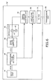
- the receiver 100A includes a reception unit 101, a timing control circuit 140, a basic pulse supplier 150, a correlator 160, an orthogonal-to-digital data selector 170, and an output unit 180.
- the reception unit 101 includes an antenna 110, a filter 120, and an amplifier 130.
- the signal is filtered at the filter 120 and amplified at the amplifier 130.
- the correlator 160 correlates similarity between each incoming pulse and the plurality of orthogonal pulse shapes from the basic pulse supplier 150 to identify the corresponding symbol. Because orthogonal pulses are used, the cross correlation between the pulses is zero. Therefore, the correlator 160 can correctly distinguish among the different pulses.
- the correlator 160 performs the correlation process at a timing modified by the timing control circuit 140 to allow for differences in time of flight between the transmitter and receiver, for example, when the transmitter, the receiver, or both are moved, and also to allow inclusion of PPM and PN code timing changes.
- all of the receivers 100A to 100D have the ability to demodulate all the different orthogonal pulse shapes assigned to the system.
- This enables implementation of an M-ary modulation scheme when only a portion of the receivers are being used. That is, when only a portion of the receivers are used, the transmitter 1 and operating receivers assign more than two pulse shapes to each of the operating receivers and assign each pulse shape correspondence with multi-bit symbols. For example, when only receivers 100A and 100B are functioning, then the receivers 100A and 100B are allotted four symbol numbers (pulse shapes) each to create a 4-ary modulation scheme in the following manner. Receiver Binary Data Symbol Number 100A 00 1 100A 01 2 100A 10 3 100A 11 4 100B 00 5 100B 01 6 100B 10 7 100B 11 8
- Fig. 6 shows a pulse train generator 5a' of a transmitter according to a second embodiment.
- the pulse train generator 5a' includes the input unit 10a, the orthogonal pulse selector 20a, and the basic pulse supplier 30a of the pulse train generator 5a of the first embodiment and further includes a modulator 40, a timing circuit controller 50, an amplitude controller 60, and a filter 70 for enhancing the effects of the system.
- the modulator 40 includes a mixer 41 and a sine wave generator 42.
- the modulator 40 performs sine modulation on the pulse train from the basic pulse supplier 30a so that the pulse bandwidth can be moved into any desired frequency domain. This facilitates complying with governmental regulations or implementing frequency hopping.
- the timing circuit controller 50 implements pulse position modulation (PPM) to increase the data rate.
- PPM pulse position modulation
- the information from the orthogonal pulse selector 20a is used to make the decision about which level or time to choose.
- the timing circuit controller 50 applies a 2-pulse position modulation to the 4-ary pulse shape modulation of the orthogonal pulse selector 20a and the basic pulse supplier 30a to encode the data stream in the following way: Receiver Binary Data Symbol Number Position 100A 000 1 0 100A 001 2 0 100A 010 3 0 100A 011 4 0 100A 100 1 1 100A 101 2 1 100A 110 3 1 100A 111 4 1 100B 000 5 0 100B 001 6 0 100B 010 7 0 100B 011 8 0 100B 100 5 1 100B 101 6 1 100B 110 7 1 100B 111 8 1 where 0 represents one position (a shift backward) and 1 represents another position (a shift forward).
- the amplitude controller 60 provides pulse amplitude modulation (PAM).
- PAM pulse amplitude modulation
- the filter 70 provides additional reduction of out-of-band noise, depending on transmit power and regulatory requirements.
- the receiver for the transmitter of the second embodiment (with the modulator 40) needs a demodulator 145 and an amplitude correlator 155 as indicated in dotted line in Fig. 5.
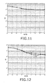
- Fig. 11 is a graphical representation of symbol error rate over bit error rate (SER/BER) resulting when two different orthogonal modified Hermite pulses were transmitted to four different users at random times over a time interval of 40ns. Sometimes the pulses were transmitted close together enough in time to overlap, resulting in interference. When the overlap was too large, a reception error occurred. If can be assumed that an even higher BER would result from the same pulse being transmitted to different users at exactly the same timing, because the pulses would always interfere in this case.
- SER/BER bit error rate
- Fig. 12 is a graphical representation of symbol error rate resulting when eight different orthogonal modified Hermite pulse shapes were transmitted at random times to four users. Because transmission timing was random, in the same manner as in the example of Fig. 11 sometimes the pulses were transmitted close together enough in time to overlap sufficiently to cause errors. However, because each pulse has a unique shape, the pulses were correctly received more frequently than in the example of Fig. 11.
- Fig. 13 is a graphical representation of when two different Hermite (orthogonal) pulses were assigned to each of four users (a total of eight pulses). That is, order 1 and 2 pulses were assigned to a first user, order 3 and 4 pulses were assigned to a second user, order 5 and 6 pulses were assigned to a third user, and order 7 and 8 pulses were assigned to a fourth user.
- One pulse of each pulse set was transmitted at the same time as the others, so pulses were perfectly aligned as though sent from a single base station. Because the pulses are all orthogonal, they did not interfere with each other at reception, resulting in good reception performance. The performance is the same as the single user case shown in Fig. 14.
- two different Hermite (orthogonal) pulses were used to transmit to a single user. Four different cases are shown: pulses with order 1 and 2, 3 and 4, 5 and 6, and 7 and 8. Each pulse set produced the same results.
- Fig 15 is a graphical representation of the effects of adding uniformly distributed random timing jitter [- ⁇ , + ⁇ ] between the transmitter and the receiver.
- the timing jitter was added in amounts of ⁇ 1% (represented by circles), ⁇ 2.5% (represented by asterisks) and ⁇ 5% (represented by squares) of the pulse width. Percentage of pulse width was used because the pulse width can be quite variable for an UWB system depending on how broad the bandwidth that is required. By specifying percentage of pulse width, the same results were achieved, regardless of whether the absolute timing jitter is 10ns or 0.1ns, which in practice are quite different.
- timing jitter when timing jitter is less than 2% of the pulse width, timing jitter has little influence, that is, less than 1dB. However, when the timing jitter is greater than 5% of the pulse width, the timing jitter causes greater error rates, that is, 4dB and higher, especially for higher orders of pulses. The reason for this increase is due to the larger number of oscillations seen in the higher pulse orders. This will impose a practical limit on the number of modified Hermite pulses that can be used in an actual communication system.
- the embodiment describes the basic pulse supplier as generating the different pulse shapes
- a memory that stores the different pulse shapes could be used instead as the supply of pulse shapes.
- the embodiment describes the timing circuit controller 50 as providing pulse position modulation (PPM).
- PPM pulse position modulation
- the timing circuit controller 50 could provide pseudo-noise (PN) code division instead of or in addition to pulse position modulation (PPM).
- PN pseudo-noise
- modified Hermite pulses as the different pulse shapes
- other different pulse shapes such as orthogonal wavelet pulses
- Any set of pulse shapes are sufficient as long as they have substantially the same pulse width.
Landscapes
- Engineering & Computer Science (AREA)
- Signal Processing (AREA)
- Computer Networks & Wireless Communication (AREA)
- Dc Digital Transmission (AREA)
- Digital Transmission Methods That Use Modulated Carrier Waves (AREA)
- Transmitters (AREA)
Abstract
Description
- The present invention relates to a wireless impulse transmitter, receiver, and method.
- Typical digital communication is performed by transmitting an analog waveform, which represents message symbols, through a channel. Ultra-wide band (UWB) communication is performed by transmitting and detecting pulse trains. The pulses have widths of less than 1 ns and bandwidth up to or beyond 3 GHz. Ultra-wide band systems are well suited for short range, fully mobile, wireless communication in a dense multipath and perhaps shadowed environment. When a base station is to send data to more than one remote receiver, the base station must transmit different pulse trains in a manner that enables the remote receivers to receive only the corresponding pulse train. For example, the base station can modulate the base pulses, known as monocycles, in time using pulse-position modulation (PPM) to encode each pulse train in a manner readable only by a receiver that is assigned the same code.
- However, all conventional methods for enabling distinction between different pulse trains require that the multi-user base station send data serially, that is, one pulse after another. Otherwise, interference between pulses will make it impossible for proper reception at the remote receivers. Therefore, the encoding schemes become more complicated as the number of remote receivers increases, so that the data rate per user decreases.
- Various respective aspects and features of the invention are defined in the appended claims. Features from the dependent claims may be combined with features of the independent claims as appropriate and not merely as explicitly set out in the claims.
- Embodiments of the present invention can provide a wireless impulse system that enables increasing the number of users without reducing the communication rates.
- A wireless impulse transmitter according to embodiments of the present invention is for transmitting pulse trains to a plurality of receivers. Each receiver is assigned two of a plurality of orthogonal pulse shapes. Each of the two pulse shapes assigned to each receiver represents either one or zero to the corresponding receiver. The inventive transmitter includes a pulse selector, a pulse supplier, and a transmission unit. The pulse selector is for selecting, from the plurality of orthogonal pulse shapes, pulse shapes corresponding to symbols of an input data stream. The pulse supplier is for supplying pulses in pulse shapes selected by the pulse selector. The transmission unit is for transmitting the pulses supplied from the pulse supplier in pulse trains, wherein pulses with pulse shapes assigned to different receivers are transmitted simultaneously.
- Because the pulses selected by the pulse selector and supplied by the pulse supplier are orthogonal, multiple pulses can be transmitted and received at the same time without causing interference. As a result, the number of user receivers can be increased without a decrease in the bit rate of the channel.
- Two real-valued functions gm(t) and gn(t), which are defined on an interval a ≤ x ≤ b, are orthogonal if:

- It is desirable that the pulse supplier supply pulse shapes having the same pulse width. When all of the pulses have the same pulse width and also the frequency band, the transmission process is greatly simplified.
- It is desirable that the pulse supplier supply pulse shapes that are based on modified Hermite polynomials. Hermite polynomials are modified to become orthogonal as follows:

- With this configuration, the pulse duration is actually the same for all values of n. That is, the pulses are constrained in time independent of the order of the pulse. In the examples in Fig. 7, the pulse duration is defined as +/- 6ns. As shown in Fig. 16, 95% or more of the energy of all pulses of Fig. 7 is contained in this pulse duration for pulses of order n = 0...8.
- There is no limit on the order of the pulses.
- Further, the orthogonality of the pulses does not change if they are differentiated. The effect of antennas is often modeled as a differentiation process.
- Distance induced attenuation does not significantly increase with the number of levels.
- Also, the pulse bandwidth is almost the same regardless of the order of the pulse, that is, for every value of n. This is important in a radio system because containing the pulse width within a certain width contains the frequency within a certain band.
- The pulses from order n > 0 have zero DC component.
- The orthogonality of the pulses is maintained despite differentiating effects of the transmitter and receiver antennas.
- The fractional bandwidth can be easily controlled by changing the center frequency. The fractional bandwidth is important when designing wideband antenna arrays, and generally the ratio of the high to low frequencies should be around 2 or 3.
- It is desirable that the pulse supplier supplies pulse shapes that are based on modified normalized Hermite polynomials. With this configuration, all the pulses in the transmitted pulse train will have almost the same height and equal energy, so that all the pulses cost the same to transmit.
- A wireless impulse receiver according to embodiments of the present invention includes a receiving unit and a correlator. The receiving unit is for receiving a data stream including pulses that have either of two different orthogonal pulse shapes. The correlator is for distinguishing correspondence between symbols and pulse shapes of the pulses in the data stream received by the receiving unit. The correlator is also for outputting symbols that correspond to the pulse shapes in the received data stream. With this configuration, the same good effects achieved by the inventive transmitter can be achieved.
- It is desirable that a synchronizing unit be further provided. The synchronizing unit synchronizes timing of reception at the receiving unit with transmission from a plurality of remote transmitters so as to receive pulses that have mutually orthogonal pulse shapes from the plurality of remote transmitters simultaneously. Because the orthogonal pulses can be received simultaneously, the reception rate of the receiver can be greatly increased.
- A method according to embodiments of the present invention for transmitting pulse trains in a wireless transmission to a plurality of receivers includes selecting, from a plurality of orthogonal pulse shapes assigned in a two-to-one correspondence with the receivers, pulse shapes corresponding to symbols of an input data stream, each of the two pulse shapes assigned to each receiver representing either one or zero to the corresponding receiver; supplying pulses in the selected pulse shapes; and transmitting the supplied pulses in pulse trains wherein pulses with pulse shapes assigned to different receivers are transmitted simultaneously. With this method, the same good effects achieved by the inventive transmitter and receiver can be achieved.
- The invention will now be described by way of example with reference to the accompanying drawings, throughout which like parts are referred to by like references, and in which:
- Fig. 1 is a block diagram showing outline of the ultra-wide band system according to a first embodiment of the present invention;
- Fig. 2 is a block diagram showing configuration of a pulse train generator of a transmitter in the system of Fig. 1;
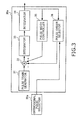
- Fig. 3 is a block diagram showing configuration of a basic pulse supplier of the pulse train generator of Fig. 2;
- Fig. 4 is a block diagram showing mathematical function of components in the basic pulse supplier of Fig. 3;
- Fig. 5 is a block diagram showing a receiver according to the first embodiment;
- Fig. 6 is a block diagram showing a pulse train generator according to a second embodiment of the present invention;
- Fig. 7 is a graphical representation showing time response of modified normalized Hermite pulses of order n = 0, 1, 2 with a PW = 8;
- Fig. 8 is a graphical representation showing autocorrelation of normalized Hermite pulses of order n = 0, 1, 2 with a PW = 8;
- Fig. 9 is a graphical representation of time response of modified normalized Hermite pulses of order n = 3, 4, 5 with a PW = 8, normalized to unit energy;
- Fig. 10 is a graphical representation of time response of modified Hermite pulses of order n = 6, 7, 8 with a PW = 8, normalized to unit energy;
- Fig. 11 is a graphical representation of symbol error rate over bit error rate (SER/BER) achieved when two different modified Hermite pulses are used to represent symbols in a digital transmission to a single receiver;
- Fig. 12 is graphical representation of symbol error rate achieved when two pulse shapes were transmitted at different times to each of four users at an interval of 40ns;
- Fig. 13 is a graphical representation of when two different Hermite (orthogonal) pulses were assigned to each of four users;
- Fig. 14 is a graphical representation showing when two different Hermite (orthogonal) pulses were assigned to each user in the same manner as in Fig. 12, but pulses were transmitted at the same time;
- Fig 15 is a graphical representation of the effects of adding uniformly distributed random timing jitter [-Δ , +Δ] between the transmitter and the receiver; and
- Fig. 16 is a graphical representation showing that 95% of energy of all pulses of Fig. 7 is contained in this pulse duration for pulses of order n = 0...8.
- Next, ultra-wide band (UWB) communication systems according to embodiments of the present invention will be described while referring to the attached drawings. According to the present invention, an ultra-wide band communication system is a system with a fractional bandwidth Bf of greater than 25%. Fractional bandwidth Bf is defined as:

- fc is center frequency;
- fh is the higher 3 dB points of the signal spectrum; and
- f1 is the lower 3 dB points of the signal spectrum.
- An ultra-wide band communication system according to a first embodiment will be described with reference to Figs. 1 to 4. As shown in Fig. 1, the system of the first embodiment includes a wireless ultra-wide
band impulse transmitter 1 and fourremote receivers 100A to 100D. In this embodiment, thetransmitter 1 is a multi-user base station and thereceivers 100A to 100D are mobile terminals. Thetransmitter 1 is capable of transmitting eight different pulse shapes that are mutually orthogonal. The eight pulse shapes are represented bysymbol numbers 1 to 8. Each of thereceivers 100A to 100D is assigned two of the eight pulse shapes (symbol numbers) to represent a binary channel, that is, 0 or 1. In this example, thereceiver 100A is assignedsymbol numbers receiver 100B is assignedsymbol numbers receiver 100C is assignedsymbol numbers receiver 100D is assignedsymbol numbers 7 and 8. This correspondence relationship is summarized as follows:Receiver Binary Data Symbol Number 100A 0 1 100A 1 2 100B 0 3 100B 1 4 100C 0 5 100C 1 6 100D 0 7 100D 1 8 - The
transmitter 1 includespulse train generators 5a to 5d in a one-to-one correspondence with thereceivers 100A to 100D. Thetransmitter 1 also includes apulse combiner 90 connected to thebasic pulse selectors 30a to 30d and atransmission unit 80 connected to thepulse combiner 90. - Each
pulse train generator 5a to 5d has substantially the same configuration, so the configuration ofpulse train generator 5a will be provided as a representative example. As shown in Fig. 2, thepulse train generator 5a includes aninput unit 10a, anorthogonal pulse selector 20a, and apulse selector 30a. Theorthogonal pulse selector 20a determines which symbols correspond to which bits in a binary data stream received from theinput unit 10a, and outputs the symbol numbers to thebasic pulse supplier 30a. In the example of Fig. 2, theinput unit 10a providesbits 0110 in a data stream to theorthogonal pulse selector 20a, which outputs thecorresponding symbol numbers basic pulse supplier 30a accordingly. Theorthogonal pulse selector 20a outputs the symbol numbers in the form of a value determined by multiplying a function (n + 1/2) times a gain (
- The
basic pulse supplier 30a generates an analog pulse shape according to the selection from theorthogonal pulse selector 20a. That is, thebasic pulse supplier 30a generates a set of different pulse shapes that correspond to the input symbol numbers. The different pulse shapes are orthogonal to each other and have substantially the same pulse width. According to the present embodiment, thebasic pulse supplier 30a supplies pulse shapes based on modified normalized Hermite polynomials, which are orthogonal as described below. - Hermite polynomials are expressed by the following equation:


 stands for derivative of h . The following is a differential equation satisfied by Hermite polynomials, as derived using equations (4) and (5):
- Hermite polynomials are not orthogonal. By definition, two real-valued functions gm(t) and gn(t), which are defined on an interval a ≤ x < b, are orthogonal if:
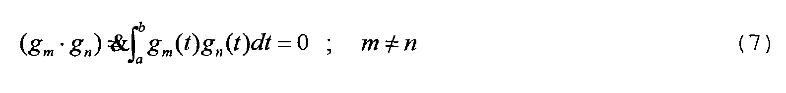
- A set of real valued functions g1(t), g2(t), g3(t), ... is called an orthogonal set of functions in the set. The nonnegative square root of (gm · gm) is called the norm of gm(t) and is denoted by∥g m ∥; thus:

- Orthonormal set of functions satisfy ∥g m ∥ for every value of m.
- Hermite polynomials are modified to become orthogonal as follows:

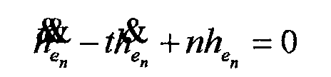
- It can be shown that modified Hermite polynomials (MHP) satisfy the following differential equations


- Denoting the Fourier transform of hn(t) as Hn(f), equations (10), (11), and (12) can be written as:


- Equations

2 f2 are examples for when n = 0. From equation (15), the transform of some higher degrees of MHP can be obtained as follows:
- For gaining added flexibility in the frequency domain, the time functions are multiplied and modified by an arbitrary phase shifted sinusoid. Hence the modulated and modified normalized Hermite polynomials (MMNHP) are defined as follows:

- Pulses based on modified normalized Hermite polynomial functions have the following properties:
- 1. The pulse duration is actually the same for all values of n.
- 2. The pulse bandwidth is almost the same for every value of n. This is important in a radio system because containing the pulse width within a certain width range contains the frequency within a certain band.
- 3. The fractional bandwidth can be easily controlled by the center frequency fc.
- 4. The pulses are mutually orthogonal.
- 5. The pulses have zero DC component.
- 6. The orthogonality of the pulses is maintained despite differentiating effects of the transmitter and receiver antennas.
- As shown in Figs. 3 and 4, the
basic pulse supplier 30a includes apulse train generator 31, anadder 32, twointegrators pulse width controller 35, and apulse order selector 36. Fig. 4 shows the mathematical function of each component of thebasic pulse supplier 30a. - The
pulse train generator 31 is the basic input of pulses and provides a pulse repetition factor (PRF) that indicates the basic time unit between pulses. According to the present embodiment, the pulse train is a pseudo-noise (PN) sequence of pulses, so specific frequency spikes due to a regular pulse train can be avoided. - The
pulse width controller 35 is a t2 mono-stable generator with gain G:
t is time. - The gain G is multiplied with the signal from the
integrator 34. The gain G is important because it determines the pulse width PW and also the bandwidth of the pulse. - The
pulse order selector 36 determines the order of the pulse according to the input from theorthogonal pulse selector 20a. Thepulse order selector 36 multiplies the value from theorthogonal pulse selector 20a with the feedback from theintegrator 34. Theadder 32 adds the product from thepulse order selector 36 with the output from thepulse width controller 35. - The
transmission unit 80 includes apower amplifier 81 and awide band antenna 82 for actually transmitting, in a wireless transmission, a pulse train of pulses generated by thepulse supplier 30a. - The
pulse train combiner 90 then combines the pulse trains from all of thepulse train generators 5a to 5d and thetransmission unit 80 transmits them over the wireless channel. - Each of the
receivers 100A to 100D has substantially same configuration in order to demodulate the incoming signals, with the exception of the two pulse shapes assigned to each. Here, an explanation will be provided for thereceiver 100A as a representative example. As shown in Fig. 5, thereceiver 100A includes areception unit 101, atiming control circuit 140, abasic pulse supplier 150, acorrelator 160, an orthogonal-to-digital data selector 170, and anoutput unit 180. Thereception unit 101 includes anantenna 110, afilter 120, and anamplifier 130. - After the
antenna 110 receives a pulse, the signal is filtered at thefilter 120 and amplified at theamplifier 130. Thecorrelator 160 correlates similarity between each incoming pulse and the plurality of orthogonal pulse shapes from thebasic pulse supplier 150 to identify the corresponding symbol. Because orthogonal pulses are used, the cross correlation between the pulses is zero. Therefore, thecorrelator 160 can correctly distinguish among the different pulses. Thecorrelator 160 performs the correlation process at a timing modified by thetiming control circuit 140 to allow for differences in time of flight between the transmitter and receiver, for example, when the transmitter, the receiver, or both are moved, and also to allow inclusion of PPM and PN code timing changes. - According to the present embodiment, all of the
receivers 100A to 100D have the ability to demodulate all the different orthogonal pulse shapes assigned to the system. This enables implementation of an M-ary modulation scheme when only a portion of the receivers are being used. That is, when only a portion of the receivers are used, thetransmitter 1 and operating receivers assign more than two pulse shapes to each of the operating receivers and assign each pulse shape correspondence with multi-bit symbols. For example, whenonly receivers receivers Receiver Binary Data Symbol Number 100A 00 1 100A 01 2 100A 10 3 100A 11 4 100B 00 5 100B 01 6 100B 10 7 100B 11 8 - Fig. 6 shows a
pulse train generator 5a' of a transmitter according to a second embodiment. Thepulse train generator 5a' includes theinput unit 10a, theorthogonal pulse selector 20a, and thebasic pulse supplier 30a of thepulse train generator 5a of the first embodiment and further includes amodulator 40, atiming circuit controller 50, anamplitude controller 60, and afilter 70 for enhancing the effects of the system. Themodulator 40 includes amixer 41 and asine wave generator 42. - The
modulator 40 performs sine modulation on the pulse train from thebasic pulse supplier 30a so that the pulse bandwidth can be moved into any desired frequency domain. This facilitates complying with governmental regulations or implementing frequency hopping. - The
timing circuit controller 50 implements pulse position modulation (PPM) to increase the data rate. The information from theorthogonal pulse selector 20a is used to make the decision about which level or time to choose. In the above-described situation, wherein only thereceivers timing circuit controller 50 applies a 2-pulse position modulation to the 4-ary pulse shape modulation of theorthogonal pulse selector 20a and thebasic pulse supplier 30a to encode the data stream in the following way:Receiver Binary Data Symbol Number Position 100A 000 1 0 100A 001 2 0 100A 010 3 0 100A 011 4 0 100A 100 1 1 100A 101 2 1 100A 110 3 1 100A 111 4 1 100B 000 5 0 100B 001 6 0 100B 010 7 0 100B 011 8 0 100B 100 5 1 100B 101 6 1 100B 110 7 1 100B 111 8 1 - The
amplitude controller 60 provides pulse amplitude modulation (PAM). The information from theorthogonal pulse selector 20a is used to make the decision about which level or time to choose. - The
filter 70 provides additional reduction of out-of-band noise, depending on transmit power and regulatory requirements. - The receiver for the transmitter of the second embodiment (with the modulator 40) needs a
demodulator 145 and anamplitude correlator 155 as indicated in dotted line in Fig. 5. - Figs. 7 and 8 show the time domain representations of modified normalized Hermite pulses of order n = 1, 2, 3 and the autocorrelations of these pulses.
- Fig. 9 is a graphical representation of time response of modified normalized Hermite pulses of order n = 3, 4, 5 with a PW = 8, normalized to unit energy.
- Fig. 10 is a graphical representation of time response of modified Hermite pulses of order n = 6, 7, 8 with a PW = 8, normalized to unit energy.
- The inventors performed several simulations to determine effectiveness of embodiments of the present invention. The results are shown in Figs. 11 to 14.
- Fig. 11 is a graphical representation of symbol error rate over bit error rate (SER/BER) resulting when two different orthogonal modified Hermite pulses were transmitted to four different users at random times over a time interval of 40ns. Sometimes the pulses were transmitted close together enough in time to overlap, resulting in interference. When the overlap was too large, a reception error occurred. If can be assumed that an even higher BER would result from the same pulse being transmitted to different users at exactly the same timing, because the pulses would always interfere in this case.
- Fig. 12 is a graphical representation of symbol error rate resulting when eight different orthogonal modified Hermite pulse shapes were transmitted at random times to four users. Because transmission timing was random, in the same manner as in the example of Fig. 11 sometimes the pulses were transmitted close together enough in time to overlap sufficiently to cause errors. However, because each pulse has a unique shape, the pulses were correctly received more frequently than in the example of Fig. 11.
- Fig. 13 is a graphical representation of when two different Hermite (orthogonal) pulses were assigned to each of four users (a total of eight pulses). That is,
order order order order 7 and 8 pulses were assigned to a fourth user. One pulse of each pulse set was transmitted at the same time as the others, so pulses were perfectly aligned as though sent from a single base station. Because the pulses are all orthogonal, they did not interfere with each other at reception, resulting in good reception performance. The performance is the same as the single user case shown in Fig. 14. In Fig. 14, two different Hermite (orthogonal) pulses were used to transmit to a single user. Four different cases are shown: pulses withorder - Fig 15 is a graphical representation of the effects of adding uniformly distributed random timing jitter [-Δ , + Δ ] between the transmitter and the receiver. The timing jitter was added in amounts of < 1% (represented by circles), <2.5% (represented by asterisks) and <5% (represented by squares) of the pulse width. Percentage of pulse width was used because the pulse width can be quite variable for an UWB system depending on how broad the bandwidth that is required. By specifying percentage of pulse width, the same results were achieved, regardless of whether the absolute timing jitter is 10ns or 0.1ns, which in practice are quite different.
- As can be seen in Fig. 15, when timing jitter is less than 2% of the pulse width, timing jitter has little influence, that is, less than 1dB. However, when the timing jitter is greater than 5% of the pulse width, the timing jitter causes greater error rates, that is, 4dB and higher, especially for higher orders of pulses. The reason for this increase is due to the larger number of oscillations seen in the higher pulse orders. This will impose a practical limit on the number of modified Hermite pulses that can be used in an actual communication system.
- While the invention has been described in detail with reference to specific embodiments thereof, it would be apparent to those skilled in the art that various changes and modifications may be made therein without departing from the spirit of the invention, the scope of which is defined by the attached claims.
- For example, although the embodiment describes the basic pulse supplier as generating the different pulse shapes, a memory that stores the different pulse shapes could be used instead as the supply of pulse shapes.
- The embodiment describes the
timing circuit controller 50 as providing pulse position modulation (PPM). However, thetiming circuit controller 50 could provide pseudo-noise (PN) code division instead of or in addition to pulse position modulation (PPM). - Although the embodiment describes using modified Hermite pulses as the different pulse shapes, other different pulse shapes, such as orthogonal wavelet pulses, can be used. Any set of pulse shapes are sufficient as long as they have substantially the same pulse width.
- In so far as the embodiments of the invention described above are implemented, at least in part, using software-controlled data processing apparatus, it will be appreciated that a computer program providing such software control and a transmission, storage or other medium by which such a computer program is provided are envisaged as aspects of the present invention.
Claims (12)
- A wireless impulse transmitter for transmitting pulse trains to a plurality of receivers, the transmitter comprising:a pulse selector for selecting, from a plurality of orthogonal pulse shapes assigned in a two-to-one correspondence with the receivers, pulse shapes corresponding to symbols of an input data stream, each of the two pulse shapes assigned to each receiver representing either one or zero to the corresponding receiver;a pulse supplier for supplying pulses in pulse shapes selected by the pulse selector; anda transmission unit for transmitting the pulses supplied from the pulse supplier in pulse trains wherein pulses with pulse shapes assigned to different receivers are transmitted simultaneously.
- A wireless impulse transmitter as claimed in claim 1, wherein the pulse supplier supplies pulse shapes having the same pulse width.
- A wireless impulse transmitter as claimed in claim 1, wherein the pulse supplier supplies pulse shapes that are based on modified Hermite polynomials.
- A wireless impulse transmitter as claimed in claim 3, wherein the pulse supplier supplies pulse shapes that are based on modified normalized Hermite polynomials.
- A wireless impulse receiver comprising:a receiving unit for receiving a data stream including pulses that have either of two different orthogonal pulse shapes; anda correlator for distinguishing correspondence between symbols and pulse shapes of the pulses in the data stream received by the receiving unit and outputting symbols that correspond to the pulse shapes in the received data stream.
- A wireless impulse receiver as claimed in claim 5, further comprising a synchronizing unit that synchronizes timing of reception at the receiving unit with transmission from a plurality of remote transmitters so as to receive pulses that have mutually orthogonal pulse shapes from the plurality of remote transmitters simultaneously.
- A wireless impulse receiver as claimed in claim 5, wherein the pulse supplier supplies pulse shapes that are based on modified Hermite polynomials.
- A wireless impulse receiver as claimed in claim 7, wherein the pulse supplier supplies pulse shapes that are based on modified normalized Hermite polynomials.
- A method for transmitting pulse trains in a wireless transmission to a plurality of receivers, the method comprising:selecting, from a plurality of orthogonal pulse shapes assigned in a two-to-one correspondence with the receivers, pulse shapes corresponding to symbols of an input data stream, each of the two pulse shapes assigned to each receiver representing either one or zero to the corresponding receiver;supplying pulses in the selected pulse shapes; andtransmitting the supplied pulses in pulse trains wherein pulses with pulse shapes assigned to different receivers are transmitted simultaneously.
- A method as claimed in claim 9, wherein pulse shapes are supplied that have the same pulse width.
- A method as claimed in claim 9, wherein pulse shapes are supplied that are based on modified Hermite polynomials.
- A method as claimed in claim 11, wherein pulse shapes are supplied that are based on modified normalized Hermite polynomials.
Applications Claiming Priority (2)
| Application Number | Priority Date | Filing Date | Title |
|---|---|---|---|
| JP2001221334A JP4644988B2 (en) | 2001-07-23 | 2001-07-23 | Wireless impulse transmitter, receiver and method |
| JP2001221334 | 2001-07-23 |
Publications (3)
| Publication Number | Publication Date |
|---|---|
| EP1280308A2 true EP1280308A2 (en) | 2003-01-29 |
| EP1280308A3 EP1280308A3 (en) | 2006-09-13 |
| EP1280308B1 EP1280308B1 (en) | 2013-03-27 |
Family
ID=19055016
Family Applications (1)
| Application Number | Title | Priority Date | Filing Date |
|---|---|---|---|
| EP20020255127 Expired - Fee Related EP1280308B1 (en) | 2001-07-23 | 2002-07-22 | Wireless impulse transmitter, receiver, and method |
Country Status (4)
| Country | Link |
|---|---|
| US (1) | US7440505B2 (en) |
| EP (1) | EP1280308B1 (en) |
| JP (1) | JP4644988B2 (en) |
| KR (1) | KR100921083B1 (en) |
Cited By (3)
| Publication number | Priority date | Publication date | Assignee | Title |
|---|---|---|---|---|
| EP1455498A1 (en) * | 2003-03-06 | 2004-09-08 | STMicroelectronics N.V. | Method and apparatus for the generation of ultra-wideband pulses |
| US8660206B2 (en) | 2003-02-25 | 2014-02-25 | Yokohama Tlo Company, Ltd. | Method of generating pulse waveform |
| EP4142228A1 (en) * | 2021-08-26 | 2023-03-01 | 3db Access AG | Device for generating transmission pulses based on multiple kernel pulses and method therefore |
Families Citing this family (9)
| Publication number | Priority date | Publication date | Assignee | Title |
|---|---|---|---|---|
| US7558310B1 (en) * | 2001-01-09 | 2009-07-07 | Urbain Alfred von der Embse | Multi-scale code division frequency/wavelet multiple access |
| KR100520150B1 (en) * | 2003-12-01 | 2005-10-10 | Ultra wide band pulse train generator | |
| US7081850B2 (en) * | 2004-06-03 | 2006-07-25 | Raytheon Company | Coherent detection of ultra wideband waveforms |
| WO2006076709A1 (en) * | 2005-01-14 | 2006-07-20 | Honeywell International Inc. | Pulse shaping optimizer in uwb receiver |
| FR2889384B1 (en) * | 2005-07-27 | 2007-10-26 | Commissariat Energie Atomique | ULTRA-WIDEBAND MULTI-ANTENNA COMMUNICATION METHOD AND DEVICE USING HERMITE PULSES |
| KR100893575B1 (en) * | 2007-05-23 | 2009-04-17 | 부산대학교 산학협력단 | Apparatus and method in ultra-wideband wireless communication system |
| TW200952411A (en) * | 2008-03-10 | 2009-12-16 | Koninkl Philips Electronics Nv | An efficient multi-band communication system |
| KR101374746B1 (en) * | 2012-07-12 | 2014-03-17 | 국방과학연구소 | Method for maintaining orthogonal property of multiple pulse and communication system thereof |
| WO2017027469A1 (en) * | 2015-08-07 | 2017-02-16 | The Board Of Regents Of The Nevada System Of Higher Education On Behalf | Efficient data transmission using orthogonal pulse shapes |
Citations (1)
| Publication number | Priority date | Publication date | Assignee | Title |
|---|---|---|---|---|
| WO2002031986A2 (en) | 2000-10-10 | 2002-04-18 | Xtremespectrum, Inc. | Generation of wavelets for data transmission |
Family Cites Families (26)
| Publication number | Priority date | Publication date | Assignee | Title |
|---|---|---|---|---|
| US3908084A (en) * | 1974-10-07 | 1975-09-23 | Bell Telephone Labor Inc | High frequency character receiver |
| US4542504A (en) * | 1983-08-22 | 1985-09-17 | At&T Bell Laboratories | Shared data receiver |
| US6275679B1 (en) * | 1985-06-24 | 2001-08-14 | The United States Of America As Represented By The Secretary Of The Air Force | Secure communication using array transmitter |
| US4759040A (en) * | 1986-02-01 | 1988-07-19 | Iwatsu Electric Co., Ltd. | Digital synchronizing circuit |
| US5253272A (en) * | 1991-03-01 | 1993-10-12 | Amp Incorporated | Digital data transmission system with adaptive predistortion of transmitted pulses |
| US5335293A (en) * | 1992-06-16 | 1994-08-02 | Key Technology, Inc. | Product inspection method and apparatus |
| US5621425A (en) * | 1992-12-24 | 1997-04-15 | Seiko Instruments Inc. | Liquid crystal display device |
| SI9300025A (en) * | 1993-01-21 | 1994-09-30 | Spase Drakul | Digital communication system in n-dimensional vector space for transmission coded waveforms in bandlimited chanels |
| US5471673A (en) * | 1994-01-28 | 1995-11-28 | Palmer; James K. | Multiple RF carrier synthesizer |
| US5677927A (en) * | 1994-09-20 | 1997-10-14 | Pulson Communications Corporation | Ultrawide-band communication system and method |
| US5832035A (en) * | 1994-09-20 | 1998-11-03 | Time Domain Corporation | Fast locking mechanism for channelized ultrawide-band communications |
| US5790516A (en) * | 1995-07-14 | 1998-08-04 | Telefonaktiebolaget Lm Ericsson | Pulse shaping for data transmission in an orthogonal frequency division multiplexed system |
| US6134215A (en) * | 1996-04-02 | 2000-10-17 | Qualcomm Incorpoated | Using orthogonal waveforms to enable multiple transmitters to share a single CDM channel |
| US6359874B1 (en) * | 1998-05-21 | 2002-03-19 | Ericsson Inc. | Partially block-interleaved CDMA coding and decoding |
| US6269075B1 (en) * | 1998-01-26 | 2001-07-31 | Nokia Mobile Phones Limited | Finger assignment in a CDMA rake receiver |
| US7076168B1 (en) | 1998-02-12 | 2006-07-11 | Aquity, Llc | Method and apparatus for using multicarrier interferometry to enhance optical fiber communications |
| US6603818B1 (en) * | 1999-09-23 | 2003-08-05 | Lockheed Martin Energy Research Corporation | Pulse transmission transceiver architecture for low power communications |
| US7406261B2 (en) * | 1999-11-02 | 2008-07-29 | Lot 41 Acquisition Foundation, Llc | Unified multi-carrier framework for multiple-access technologies |
| AU1922100A (en) * | 1999-11-29 | 2001-06-04 | Multispectral Solutions, Inc. | Ultra-wideband data transmission system |
| US6807145B1 (en) * | 1999-12-06 | 2004-10-19 | Lucent Technologies Inc. | Diversity in orthogonal frequency division multiplexing systems |
| US6763057B1 (en) * | 1999-12-09 | 2004-07-13 | Time Domain Corporation | Vector modulation system and method for wideband impulse radio communications |
| US6937667B1 (en) * | 2000-03-29 | 2005-08-30 | Time Domain Corporation | Apparatus, system and method for flip modulation in an impulse radio communications system |
| US6959031B2 (en) * | 2000-07-06 | 2005-10-25 | Time Domain Corporation | Method and system for fast acquisition of pulsed signals |
| US6354946B1 (en) * | 2000-09-20 | 2002-03-12 | Time Domain Corporation | Impulse radio interactive wireless gaming system and method |
| US6680727B2 (en) * | 2000-10-17 | 2004-01-20 | Qualcomm Incorporated | Method and apparatus for canceling pilot interference in a CDMA communication system |
| US6917581B2 (en) * | 2001-07-17 | 2005-07-12 | Ipr Licensing, Inc. | Use of orthogonal or near orthogonal codes in reverse link |
-
2001
- 2001-07-23 JP JP2001221334A patent/JP4644988B2/en not_active Expired - Fee Related
-
2002
- 2002-07-22 EP EP20020255127 patent/EP1280308B1/en not_active Expired - Fee Related
- 2002-07-22 US US10/200,953 patent/US7440505B2/en not_active Expired - Fee Related
- 2002-07-23 KR KR20020043156A patent/KR100921083B1/en not_active IP Right Cessation
Patent Citations (1)
| Publication number | Priority date | Publication date | Assignee | Title |
|---|---|---|---|---|
| WO2002031986A2 (en) | 2000-10-10 | 2002-04-18 | Xtremespectrum, Inc. | Generation of wavelets for data transmission |
Cited By (4)
| Publication number | Priority date | Publication date | Assignee | Title |
|---|---|---|---|---|
| US8660206B2 (en) | 2003-02-25 | 2014-02-25 | Yokohama Tlo Company, Ltd. | Method of generating pulse waveform |
| EP1455498A1 (en) * | 2003-03-06 | 2004-09-08 | STMicroelectronics N.V. | Method and apparatus for the generation of ultra-wideband pulses |
| US7321608B2 (en) | 2003-03-06 | 2008-01-22 | Stmicroelectronics N.V. | Process and device for generating pulses for the transmission of a pulsed signal of the ultra wideband type |
| EP4142228A1 (en) * | 2021-08-26 | 2023-03-01 | 3db Access AG | Device for generating transmission pulses based on multiple kernel pulses and method therefore |
Also Published As
| Publication number | Publication date |
|---|---|
| JP4644988B2 (en) | 2011-03-09 |
| EP1280308A3 (en) | 2006-09-13 |
| US7440505B2 (en) | 2008-10-21 |
| KR20030011600A (en) | 2003-02-11 |
| US20030128772A1 (en) | 2003-07-10 |
| JP2003037638A (en) | 2003-02-07 |
| EP1280308B1 (en) | 2013-03-27 |
| KR100921083B1 (en) | 2009-10-08 |
Similar Documents
| Publication | Publication Date | Title |
|---|---|---|
| Ghavami et al. | A novel UWB pulse shape modulation system | |
| US5341396A (en) | Multi-rate spread system | |
| US6912240B2 (en) | Method and apparatus for generating a large number of codes having desirable correlation properties | |
| US7082153B2 (en) | Variable spacing pulse position modulation for ultra-wideband communication links | |
| CA2210149C (en) | Sequence constructions for delay-and-correlate transmitted reference signaling | |
| US20050175068A1 (en) | Randomly changing pulse polarity and phase in an UWB signal for power spectrum density shaping | |
| EP1280308B1 (en) | Wireless impulse transmitter, receiver, and method | |
| CN1698331B (en) | Method and system for eliminating spectral lines in time hopping ultra wide bandwidth signal | |
| US10797920B1 (en) | High-entropy continuous phase modulation data transmitter | |
| WO2003071766A1 (en) | M-ary orthagonal coded communications method and system | |
| US7248659B2 (en) | Method for adjusting acquisition speed in a wireless network | |
| JP2009523359A (en) | Method and apparatus for generating dynamically changing time hopping sequences for UWB signals | |
| US7184719B2 (en) | Method for operating multiple overlapping wireless networks | |
| EP0817396B1 (en) | Spread spectrum communications system with transmitted reference | |
| KR20060045522A (en) | Frequency staggered frequency shift keying modulation | |
| Aue et al. | Multi-carrier spread spectrum modulation with reduced dynamic range | |
| EP1774665A2 (en) | System and method for the mitigation of spectral lines in an ultrawide bandwitdh transceiver | |
| EP0589683B1 (en) | Method for frequency comb spread spectrum modulation | |
| US7702033B2 (en) | Modulating apparatus, mobile communication system, modulating method, and communication method | |
| US7280601B2 (en) | Method for operating multiple overlapping wireless networks | |
| JP2005130504A (en) | System and device for modulating uwb pulse sequences | |
| JP4715067B2 (en) | Multi-pulse generator, wireless impulse transmitter, and pulse generation method | |
| Dilmaghani et al. | UWB multiple-pulse generator and transmitter | |
| JP2003037639A (en) | Wireless impulse transmitter, receiver and method | |
| WO2006073371A1 (en) | Method and apparatus for pulse mapping in impulse radio modulation |
Legal Events
| Date | Code | Title | Description |
|---|---|---|---|
| PUAI | Public reference made under article 153(3) epc to a published international application that has entered the european phase |
Free format text: ORIGINAL CODE: 0009012 |
|
| AK | Designated contracting states |
Designated state(s): AT BE BG CH CY CZ DE DK EE ES FI FR GB GR IE IT LI LU MC NL PT SE SK TR |
|
| AX | Request for extension of the european patent |
Extension state: AL LT LV MK RO SI |
|
| PUAL | Search report despatched |
Free format text: ORIGINAL CODE: 0009013 |
|
| AK | Designated contracting states |
Kind code of ref document: A3 Designated state(s): AT BE BG CH CY CZ DE DK EE ES FI FR GB GR IE IT LI LU MC NL PT SE SK TR |
|
| AX | Request for extension of the european patent |
Extension state: AL LT LV MK RO SI |
|
| RIC1 | Information provided on ipc code assigned before grant |
Ipc: H04L 25/03 20060101ALI20060804BHEP Ipc: H04L 27/00 20060101AFI20021101BHEP Ipc: H04B 1/69 20060101ALI20060804BHEP Ipc: H04L 5/02 20060101ALI20060804BHEP |
|
| 17P | Request for examination filed |
Effective date: 20070223 |
|
| AKX | Designation fees paid |
Designated state(s): DE FR GB |
|
| 17Q | First examination report despatched |
Effective date: 20090205 |
|
| REG | Reference to a national code |
Ref country code: DE Ref legal event code: R079 Ref document number: 60244692 Country of ref document: DE Free format text: PREVIOUS MAIN CLASS: H04L0027000000 Ipc: H04B0001717000 |
|
| RIC1 | Information provided on ipc code assigned before grant |
Ipc: H04B 1/717 20110101AFI20120427BHEP Ipc: H04L 5/02 20060101ALI20120427BHEP Ipc: H04L 27/00 20060101ALI20120427BHEP Ipc: H04L 25/03 20060101ALI20120427BHEP |
|
| GRAP | Despatch of communication of intention to grant a patent |
Free format text: ORIGINAL CODE: EPIDOSNIGR1 |
|
| GRAS | Grant fee paid |
Free format text: ORIGINAL CODE: EPIDOSNIGR3 |
|
| GRAA | (expected) grant |
Free format text: ORIGINAL CODE: 0009210 |
|
| AK | Designated contracting states |
Kind code of ref document: B1 Designated state(s): DE FR GB |
|
| REG | Reference to a national code |
Ref country code: GB Ref legal event code: FG4D |
|
| REG | Reference to a national code |
Ref country code: DE Ref legal event code: R096 Ref document number: 60244692 Country of ref document: DE Effective date: 20130529 |
|
| PLBE | No opposition filed within time limit |
Free format text: ORIGINAL CODE: 0009261 |
|
| STAA | Information on the status of an ep patent application or granted ep patent |
Free format text: STATUS: NO OPPOSITION FILED WITHIN TIME LIMIT |
|
| 26N | No opposition filed |
Effective date: 20140103 |
|
| REG | Reference to a national code |
Ref country code: DE Ref legal event code: R097 Ref document number: 60244692 Country of ref document: DE Effective date: 20140103 |
|
| PGFP | Annual fee paid to national office [announced via postgrant information from national office to epo] |
Ref country code: DE Payment date: 20140721 Year of fee payment: 13 |
|
| PGFP | Annual fee paid to national office [announced via postgrant information from national office to epo] |
Ref country code: FR Payment date: 20140721 Year of fee payment: 13 Ref country code: GB Payment date: 20140721 Year of fee payment: 13 |
|
| REG | Reference to a national code |
Ref country code: DE Ref legal event code: R119 Ref document number: 60244692 Country of ref document: DE |
|
| GBPC | Gb: european patent ceased through non-payment of renewal fee |
Effective date: 20150722 |
|
| PG25 | Lapsed in a contracting state [announced via postgrant information from national office to epo] |
Ref country code: DE Free format text: LAPSE BECAUSE OF NON-PAYMENT OF DUE FEES Effective date: 20160202 Ref country code: GB Free format text: LAPSE BECAUSE OF NON-PAYMENT OF DUE FEES Effective date: 20150722 |
|
| REG | Reference to a national code |
Ref country code: FR Ref legal event code: ST Effective date: 20160331 |
|
| PG25 | Lapsed in a contracting state [announced via postgrant information from national office to epo] |
Ref country code: FR Free format text: LAPSE BECAUSE OF NON-PAYMENT OF DUE FEES Effective date: 20150731 |