EP1278314B1 - Monitoring unit for optical burst signals - Google Patents
Monitoring unit for optical burst signals Download PDFInfo
- Publication number
- EP1278314B1 EP1278314B1 EP01440225A EP01440225A EP1278314B1 EP 1278314 B1 EP1278314 B1 EP 1278314B1 EP 01440225 A EP01440225 A EP 01440225A EP 01440225 A EP01440225 A EP 01440225A EP 1278314 B1 EP1278314 B1 EP 1278314B1
- Authority
- EP
- European Patent Office
- Prior art keywords
- burst
- signals
- monitoring unit
- detector
- comparator
- Prior art date
- Legal status (The legal status is an assumption and is not a legal conclusion. Google has not performed a legal analysis and makes no representation as to the accuracy of the status listed.)
- Expired - Lifetime
Links
Images
Classifications
-
- H—ELECTRICITY
- H04—ELECTRIC COMMUNICATION TECHNIQUE
- H04L—TRANSMISSION OF DIGITAL INFORMATION, e.g. TELEGRAPHIC COMMUNICATION
- H04L1/00—Arrangements for detecting or preventing errors in the information received
- H04L1/20—Arrangements for detecting or preventing errors in the information received using signal quality detector
-
- H—ELECTRICITY
- H04—ELECTRIC COMMUNICATION TECHNIQUE
- H04B—TRANSMISSION
- H04B10/00—Transmission systems employing electromagnetic waves other than radio-waves, e.g. infrared, visible or ultraviolet light, or employing corpuscular radiation, e.g. quantum communication
- H04B10/07—Arrangements for monitoring or testing transmission systems; Arrangements for fault measurement of transmission systems
- H04B10/075—Arrangements for monitoring or testing transmission systems; Arrangements for fault measurement of transmission systems using an in-service signal
- H04B10/079—Arrangements for monitoring or testing transmission systems; Arrangements for fault measurement of transmission systems using an in-service signal using measurements of the data signal
- H04B10/0795—Performance monitoring; Measurement of transmission parameters
- H04B10/07953—Monitoring or measuring OSNR, BER or Q
Definitions
- the invention relates to a monitoring unit, in particular for optical burst signals.
- an optical synchronous network such as a DWDM-SDH / SONET network
- DWDM Dense Wavelength Division Multiplex
- SDH Synchronous Digital Hierarchy
- SONET Synchronous Optical Network.
- Q-factor measurement is performed, which directly reflects the quality of the optical signal; Q stands for the Gaussian error integral. Q is obtained from the observation of the analog signal on the electrical level with its amplitude and phase characteristics. The method relies on targeted mis-sampling to simulate poor signal-to-noise ratio and increased bit error rate.
- Statistical methods can then be used to determine the Q factor, which corresponds to the conditions for optimal sampling.
- the principle of the Q-factor measuring device is based on a random sampling of the eye pattern.
- a comparator operates as a center sampler with fixed amplitude threshold and fixed phase, while a different comparator as a measuring scanner can vary these two parameters.
- Results of the two comparators are compared by an exclusive OR circuit and differences are counted as bit errors.
- the method is limited to synchronous, time-continuous signals with a stable, previously known sampling clock phase.
- WO 01/20452 A1 a protocol and bitratenunabhaengiges test system is known. It is used to detect bit errors in a digital communication channel, regardless of format or transmission rate.
- the test system includes two threshold detectors for determining whether the received signal in amplitude is between a minimum and a maximum value. Furthermore, a phase control is provided. By scanning, an eye measurement is performed.
- EP 0 999 670 A2 discloses a method for measuring the signal quality of a digital communication transmission system.
- a scanner with adjustable DC threshold, a detection device for determining the bit rate and a clock generator synchronized to the input signal are used for this purpose.
- the monitoring unit which may also be referred to as a measuring circuit, has to monitor optical bursts of fixed and / or variable length.
- the individual bursts are separated with so-called guard bands. From burst to burst, signal level fluctuations in the range of a few dB can occur.
- the clock frequency and phase angle can vary from burst to burst. Each burst has a short, pre-defined preamp for clock and amplitude recovery.
- the circuit according to the invention allows a scaling of the burst signal amplitude to be measured.
- the circuit also allows very fast burst clock recovery, which allows adjustment of the measurement to the current burst.
- the circuit also allows start-of-burst detection, which roughly makes the start time of a current burst based on the detection of the guard band. In a downstream burst synchronization logic, a fine determination of the start of the payload of the burst is performed.
- a basic idea of the invention is to synchronize each received burst and to determine for each burst a variable and a fixed amplitude threshold as well as a variable and a fixed phase position value.
- each burst included in the Q-factor measurement alternatively only every second burst can be synchronized and the corresponding values determined.
- the number the bursts flowing into the measurement can be selected at equidistant intervals, for example every, every second, every third, or, for example, at irregular intervals, for example selected by a random number generator.
- the invention is not limited to the monitoring of optical bursts, but may equally well be used for the monitoring of electrical bursts.
- the resulting error signal from the comparisons of the amplitude threshold values and the phase position values is passed on by means of a gate or not.
- the gate is controlled by the synchronization logic such that only the payload information of the burst data stream is used for the pseudo error measurement.
- Software-based processing extrapolates to the current bit error rate. Thus, early signal degradation can be detected.
- the header and control information of each burst is at least partially monitored and processed.
- the header and control information is used to distinguish between special burst flows, special named burst flows, and special switched paths, so-called label switched paths.
- the latter contain special header information, the labels.
- the inclusion of header and / or control information allows the measurement of specific, selected burst data streams, e.g. Flows, Connections, Label Switched Paths, with the ability to track such burst streams throughout the network.
- IP-based optical networks and optical terabit routing nodes are of particular interest to the telecom and data industries.
- the present invention provides performance monitoring that can be used at any point in the network or node, especially in an optically transparent domain called Optical Transparency Domain to monitor burst signals without special knowledge of the transport protocol used.
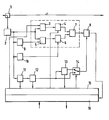
- the figure shows a monitoring unit according to the invention for optical burst signals.
- Optical networks are increasingly based on asynchronous, packet-oriented networks, e.g. ATM or Internet.
- burst-to-burst variations in signal level, clock frequency, and phase may occur.
- the monitoring unit takes these variations into account in the Q-factor measurement, which can be called a signal quality measurement, and performs a separate measurement for each burst.
- Each burst is synchronized and four measurement parameters are determined for each burst.
- the measurement parameters include a variable amplitude threshold, a fixed amplitude threshold, a variable phase position value, and a fixed phase position value.
- the eye diagram is evaluated at varying amplitude thresholds and sampling clock phases. This performs a pseudo-error measurement.
- the Q-factor and the current bit error rate are extrapolated and estimated from the measured values.
- the actual bit error measurement of a data signal is then determined at the end of a transmission path through the network in a receiver taking into account decoding, e.g. Viterbi decoder, error correction, e.g. Forward Error Correction, etc., where such a receiver is not part of the monitoring unit described here.
- the monitoring unit includes a detector for a Q-factor measurement as a function of at least one variable and at least one fixed amplitude threshold value and at least one variable and at least one fixed phase position value, which includes a burst amplitude detector 9 for generating a fixed amplitude threshold for each burst, a burst clock recovery 10 for generating a fixed phase position value for each burst, a burst detector 11 for detecting the start of a burst, and a control logic 15 for generating a variable amplitude Threshold and a variable phase position value for each burst.
- a detector for a Q-factor measurement as a function of at least one variable and at least one fixed amplitude threshold value and at least one variable and at least one fixed phase position value which includes a burst amplitude detector 9 for generating a fixed amplitude threshold for each burst, a burst clock recovery 10 for generating a fixed phase position value for each burst, a burst detector 11 for detecting
- the monitoring unit is connected via an asymmetrical optical coupler 1 to an optical line.
- the optical coupler 1 for example, decouples 10% of the signal level of the received signals and forwards them to an optical / electrical converter 2; the remaining 90% are e.g. forwarded to an optical receiver for data evaluation.
- the received optical burst signals are converted into electrical signals and then forwarded to five components.
- the forwarding takes place to a first comparator 3, a second comparator 5, the burst amplitude detector 9, the burst clock recovery 10 and the burst detector 11.
- the amplitudes of the electrical signal are compared with variable amplitude thresholds. For each burst, a new, variable amplitude threshold is determined.
- the amplitudes of the electrical signal are compared with fixed amplitude thresholds. For each burst, a new, fixed amplitude threshold is determined. The determination takes place in the amplitude detector 9, which selects an average, for example in the form of a fixed threshold voltage.
- the comparator 3 is followed by a decision maker 4.
- the output signal supplied by the comparator 3 is sampled, in response to a variable phase. For each burst a new, variable phasing value is determined.
- a variable amplitude threshold value and a variable phase angle value flow into the output signal of the decoder per burst.
- the comparator 5 is followed by a decision maker 6.
- the output signal supplied by the comparator 5 is sampled, in response to a fixed phase.
- a new, fixed phasing value is determined.
- a fixed amplitude threshold value and a fixed phase position value flow into the output signal of the decoder per burst.
- the determination of the fixed phase position value takes place in the burst clock recovery 10, which selects a mean value of a fixed phase from the sampling clock.
- Gate 8 provides an error signal which is fed to a processing unit 16.
- the processing unit 16 is, for example, a suitably programmed microprocessor. It is fed with control data for calculating extrapolation and estimation. From the error signal and the control data, the processing unit 16 determines an estimate of the Q-factor output via an output and used to monitor and control the network, e.g. to adjust the signal power at the transmitting end or to reconfigure the network if the signal quality of the respective monitored path falls below certain limits.
- the burst detector 11 is used to detect the beginning of a burst. For this purpose, a start-of-burst detection is performed, which performs a rough determination of the start time of a current burst based on the detection of the guard band.
- This start-of-burst information is provided on the one hand to the control logic 15 and on the other hand one Downstream burst synchronization logic 12, which makes a fine determination of the start of the payload of the burst.
- This start-of-payload information is provided to the control logic 15.
- the control logic 15 generates from the start-of-burst and the start-of-payload information as well as other information received from the processing unit 16 and containing the eye diagram information, a variable amplitude threshold and a variable phase lag value every burst.
- the control logic 15 is embodied, for example, as a correspondingly programmed microprocessor.
- Control logic 15 and processing unit 16 can also be implemented jointly on a microprocessor, digital signal processor, FPGA or the like and have at least one data interface for the purpose of data exchange.
- the start-of-payload information is further supplied to an extraction unit 13 and a switch 14 and the control logic 15th
- the extraction unit 13 is used for extraction of the header and / or control information.
- the header information and / or the control information is used for the selective measurement of special bursts and is forwarded to the switch 14 and to the control logic 15th
- Switch 14 is driven by control logic 15 which selects which variant of the measurement to perform, a general Q-factor measurement for all bursts, or a selective Q-factor measurement for specific bursts.
- the start-of-payload information is forwarded as a control signal to the gate 8, for the second variant, the header information.
- the variable amplitude threshold values and the variable phase angle values are additionally determined as a function of the header information.
- Extraction unit 13 and switch 14 are optional. If no Q-factor measurement or estimation of special bursts is provided, then you can a direct connection of output burst synchronization logic 12 and control input gate 8 are replaced.
Description
Die Erfindung betrifft eine Überwachungseinheit insbesondere für optische Burst-Signale.The invention relates to a monitoring unit, in particular for optical burst signals.
Zur Bestimmung der Performance eines optischen synchronen Netzes, z.B. eines DWDM-SDH/SONET-Netzes, ist bekannt, die Signalqualität optischer Verbindungen während des Betriebes durch Beobachtung der Amplituden- und Phasenverteilung des optischen Signals zu messen und daraus eine Abschätzung der Bitfehlerhäufigkeit abzuleiten; DWDM=Dense Wavelength Division Multiplex, SDH=Synchronous Digital Hierarchy, SONET=Synchronous Optical Network. Dazu wird eine Q-Faktor-Messung durchgeführt, die direkt die Qualität des optischen Signals widerspiegelt; Q steht dabei für das Gaußsche Fehlerintegral. Gewonnen wird Q aus der Beobachtung des analogen Signals auf der elektrischen Ebene mit seinem Amplituden- und Phasenverlauf. Das Verfahren beruht auf gezielter Fehlabtastung, um einen schlechten Signal-Rausch-Abstand und eine erhöhte Bitfehlerhäufigkeit zu simulieren. Mit statistischen Methoden lässt sich dann der Q-Faktor ermitteln, der den Verhältnissen bei optimaler Abtastung entspricht. Das Prinzip des Q-Faktor Messgerätes beruht auf einer stichprobenartigen Abtastung des Augenmusters. In einem Zweiweg-Detektor arbeitet ein Komparator als Mittenabtaster mit fester Amplitudenschwelle und fester Phasenlage, während ein anderer Komparator als Messabtaster diese beiden Parameter variieren kann. DieTo determine the performance of an optical synchronous network, such as a DWDM-SDH / SONET network, it is known to measure the signal quality of optical links during operation by observing the amplitude and phase distribution of the optical signal and derive therefrom an estimate of the bit error rate; DWDM = Dense Wavelength Division Multiplex, SDH = Synchronous Digital Hierarchy, SONET = Synchronous Optical Network. For this purpose, a Q-factor measurement is performed, which directly reflects the quality of the optical signal; Q stands for the Gaussian error integral. Q is obtained from the observation of the analog signal on the electrical level with its amplitude and phase characteristics. The method relies on targeted mis-sampling to simulate poor signal-to-noise ratio and increased bit error rate. Statistical methods can then be used to determine the Q factor, which corresponds to the conditions for optimal sampling. The principle of the Q-factor measuring device is based on a random sampling of the eye pattern. In a two-way detector, a comparator operates as a center sampler with fixed amplitude threshold and fixed phase, while a different comparator as a measuring scanner can vary these two parameters. The
Ergebnisse der beiden Komparatoren werden von einer Exklusiv-Oder-Schaltung verglichen und Differenzen als Bitfehler gezählt. Das Verfahren ist auf synchrone, zeitkontinuierliche Signale mit einer stabilen, vorbekannten Sampling-Taktphase beschränkt.Results of the two comparators are compared by an exclusive OR circuit and differences are counted as bit errors. The method is limited to synchronous, time-continuous signals with a stable, previously known sampling clock phase.
Aus WO 01/20452 A1 ist ein protokoll- und bitratenunabhaengiges Testsystem bekannt. Es dient der Detektion von Bitfehlern in einem digitalen Kommunikationskanal unabhaengig vom Format oder der Uebertragungsrate. Das Testsystem beinhaltet zwei Schwellwertdetektoren zwecks Feststellung, ob das empfangene Signal bezueglichd er Amplitude zwischen einem minimalen und einem maximalen Wert liegt. Ferner ist eine Phasenregelung vorgesehen. Durch Scannen wird eine Augenmessung durchgefuehrt.From WO 01/20452 A1 a protocol and bitratenunabhaengiges test system is known. It is used to detect bit errors in a digital communication channel, regardless of format or transmission rate. The test system includes two threshold detectors for determining whether the received signal in amplitude is between a minimum and a maximum value. Furthermore, a phase control is provided. By scanning, an eye measurement is performed.
Aus EP 0 999 670 A2 ist ein Verfahren zur Messung der Signalguete eines digitalen Nachrichtenuebertragungssystems bekannt. Es wird dazu insbesondere eine Abtasteinrichtung mit einstellbarer Gleichspannungsschwelle, eine Detektionsvorrichtung zur Ermittlung der Bitrate und ein auf das Eingangssignal synchronisierter Taktgenerator verwendet.EP 0 999 670 A2 discloses a method for measuring the signal quality of a digital communication transmission system. In particular, a scanner with adjustable DC threshold, a detection device for determining the bit rate and a clock generator synchronized to the input signal are used for this purpose.
Aufgabe der Erfindung ist es, eine Überwachungseinheit insbesondere für optische Burst-Signale in optischen, asynchronen Netzen, z.B. basierend auf Internet oder ATM zu schaffen, ATM=Asynchronous Transfer Mode.The object of the invention is to provide a monitoring unit, in particular for optical burst signals in optical, asynchronous networks, e.g. based on Internet or ATM ATM = Asynchronous Transfer Mode.
Gelöst wird diese Aufgabe durch eine Überwachungseinheit nach Anspruch 1.This object is achieved by a monitoring unit according to claim 1.
Die Überwachungseinheit, die auch als Messschaltung bezeichnet werden kann, hat optische Bursts fester und/oder variabler Länge zu überwachen. Die einzelnen Bursts sind mit sogenannten Guard Bands voneinander getrennt. Von Burst zu Burst können Signalpegelschwankungen im Bereich von einigen dB auftreten. Zudem kann die Taktfrequenz und die Phasenlage von Burst zu Burst variieren. Jeder Burst hat eine kurze, vordefinierte Preambel zur Takt- und Amplitudenrückgewinnung.The monitoring unit, which may also be referred to as a measuring circuit, has to monitor optical bursts of fixed and / or variable length. The individual bursts are separated with so-called guard bands. From burst to burst, signal level fluctuations in the range of a few dB can occur. In addition, the clock frequency and phase angle can vary from burst to burst. Each burst has a short, pre-defined preamp for clock and amplitude recovery.
Die erfindungsgemäße Schaltung erlaubt eine Skalierung der zu messenden Burst-Signalamplitude. Die Schaltung ermöglicht ferner eine sehr schnelle Burst-Taktrückgewinnung, die ein Justieren der Messung auf den aktuellen Burst ermöglicht. Die Schaltung ermöglicht zudem eine Start-of-Burst Detektion, die eine grobe Bestimmung des Startzeitpunktes eines aktuellen Bursts basierend auf der Detektion des Guard Bands durchführt. In einer nachgeschalteten Burst-Synchronisationslogik wird eine feine Bestimmung des Starts der Payload des Bursts durchgeführt.The circuit according to the invention allows a scaling of the burst signal amplitude to be measured. The circuit also allows very fast burst clock recovery, which allows adjustment of the measurement to the current burst. The circuit also allows start-of-burst detection, which roughly makes the start time of a current burst based on the detection of the guard band. In a downstream burst synchronization logic, a fine determination of the start of the payload of the burst is performed.
Ein Grundgedanke der Erfindung liegt darin, jeden empfangenen Burst zu synchronisieren und für jeden Burst einen variablen und einen festen Amplituden-Schwellwert sowie einen variablen und einen festen Phasenlagen-Wert zu ermitteln. Anstelle jeden Burst in die Q-Faktor Messung einfließen zu lassen, kann alternativ auch nur jede zweite Burst synchronisiert werden und die entsprechenden Werte ermittelt werden. Die Anzahl der in die Messung einfließenden Bursts kann in äquidistanten Abständen ausgewählt werden, z.B. jeder, jeder zweite, jeder dritte, oder beispielsweise in unregelmäßigen Abständen erfolgen, z.B. ausgewählt durch einen Zufallsgenerator. Die Erfindung ist nicht auf die Überwachung optischer Bursts beschränkt, sondern kann ebenso gut für die Überwachung elektrischer Bursts verwendet werden.A basic idea of the invention is to synchronize each received burst and to determine for each burst a variable and a fixed amplitude threshold as well as a variable and a fixed phase position value. Instead of having each burst included in the Q-factor measurement, alternatively only every second burst can be synchronized and the corresponding values determined. The number the bursts flowing into the measurement can be selected at equidistant intervals, for example every, every second, every third, or, for example, at irregular intervals, for example selected by a random number generator. The invention is not limited to the monitoring of optical bursts, but may equally well be used for the monitoring of electrical bursts.
Das resultierende Fehlersignal aus den Vergleichen der Amplituden-Schwellwerte und der Phasenlagen-Werte wird mittels eines Gate weitergeleitet oder nicht. Das Gate wird durch die Synchronisationslogik derart gesteuert, dass nur die Payload Information des Burst Datenstroms für die Pseudo Fehlermessung genutzt wird. Mittels einer Software basierten Verarbeitung wird eine Extrapolation auf die aktuelle Bitfehlerrate durchgeführt. Somit können frühzeitig Signalverschlechterungen erkannt werden.The resulting error signal from the comparisons of the amplitude threshold values and the phase position values is passed on by means of a gate or not. The gate is controlled by the synchronization logic such that only the payload information of the burst data stream is used for the pseudo error measurement. Software-based processing extrapolates to the current bit error rate. Thus, early signal degradation can be detected.
Bei einer vorteilhaften Ausgestaltung der Erfindung wird die Header- und Steuerinformation jedes Bursts zumindest teilweise überwacht und verarbeitet. Zusätzlich zur Q-Faktor Messung des gesamten Burst Datenstroms wird die Header- und Steuerinformation dazu benutzt, zu unterscheiden zwischen speziellen Burst Aufkommen, speziellensogenannten Burst Flows, und besonderen, geschalteten Pfaden, sogenannten Label Switched Paths. Letztere beinhalten eine spezielle Header-Information, die Labels. Allgemein ermöglicht die Einbeziehung von Header- und/oder Steuerinformationen die Messung spezieller, selektierter Burst Datenströme, z.B. Flows, Connections, Label Switched Paths, mit der Möglichkeit solche Burstströme in gesamten Netz zu verfolgen.In an advantageous embodiment of the invention, the header and control information of each burst is at least partially monitored and processed. In addition to the Q-factor measurement of the entire burst data stream, the header and control information is used to distinguish between special burst flows, special named burst flows, and special switched paths, so-called label switched paths. The latter contain special header information, the labels. In general, the inclusion of header and / or control information allows the measurement of specific, selected burst data streams, e.g. Flows, Connections, Label Switched Paths, with the ability to track such burst streams throughout the network.
IP basierte optische Netze und optische Terabit Routing Knoten sind von besonderem Interesse für die Telekom- und Datenindustrie. Die vorliegende Erfindung stellt eine Performance-Überwachung zur Verfügung, die an jeder Stelle des Netzes oder Knotens eingesetzt werden kann, insbesondere in einer optisch transparenten Domäne, der sogenannten Optical Transparency Domain, um Burst-Signale ohne spezielle Vorkenntnisse des verwendeten Transportprotokolls zu überwachen.IP-based optical networks and optical terabit routing nodes are of particular interest to the telecom and data industries. The present invention provides performance monitoring that can be used at any point in the network or node, especially in an optically transparent domain called Optical Transparency Domain to monitor burst signals without special knowledge of the transport protocol used.
Im folgenden wird ein Ausführungsbeispiel der Erfindung unter Zuhilfenahme einer Figur erläutert.In the following an embodiment of the invention will be explained with the aid of a figure.
Die Figur zeigt eine erfindungsgemäße Überwachungseinheit für optische Burst-Signale.The figure shows a monitoring unit according to the invention for optical burst signals.
Optische Netze basieren zunehmend auf asynchronen, paketorientierten Netzen wie z.B. ATM oder Internet. In solchen optischen Netzen können von Burst zu Burst Variationen im Signalpegel, in der Taktfrequenz und in der Phasenlage auftreten. Die Überwachungseinheit berücksichtigt bei der Q-Faktor-Messung, die als eine Signalgüte-Messung bezeichnet werden kann, diese Variationsmöglichkeiten und führt für jeden Burst eine separate Messung durch. Dazu wird jeder Burst synchronisiert und für jeden Burst werden vier Messparameter ermittelt. Die Messparameter enthalten einen variablen Amplituden-Schwellwert, einen festen Amplituden-Schwellwert, einen variablen Phasenlagen-Wert und einen festen Phasenlagen-Wert. Das Augendiagramm wird bei variierenden Amplituden-Schwellwerten und Sampling-Taktphasen ausgewertet. Damit wird eine Pseudo-Fehlermessung durchgeführt. Der Q-Faktor und die aktuelle Bitfehlerrate werden ausgehend von den gemessenen Werten extrapoliert und geschätzt. Die eigentliche Bitfehlermessung eines Datensignals wird aber dann am Ende eines Übertragungspfades durch das Netz in einem Empfänger bestimmt unter Berücksichtigung von Dekodierung, z.B. Viterbi-Dekoder, Fehlerkorrektur, z.B. Forward Error Correction, etc, wobei ein solcher Empfänger nicht Teil der hier beschriebenen Überwachungseinheit ist.Optical networks are increasingly based on asynchronous, packet-oriented networks, e.g. ATM or Internet. In such optical networks, burst-to-burst variations in signal level, clock frequency, and phase may occur. The monitoring unit takes these variations into account in the Q-factor measurement, which can be called a signal quality measurement, and performs a separate measurement for each burst. Each burst is synchronized and four measurement parameters are determined for each burst. The measurement parameters include a variable amplitude threshold, a fixed amplitude threshold, a variable phase position value, and a fixed phase position value. The eye diagram is evaluated at varying amplitude thresholds and sampling clock phases. This performs a pseudo-error measurement. The Q-factor and the current bit error rate are extrapolated and estimated from the measured values. However, the actual bit error measurement of a data signal is then determined at the end of a transmission path through the network in a receiver taking into account decoding, e.g. Viterbi decoder, error correction, e.g. Forward Error Correction, etc., where such a receiver is not part of the monitoring unit described here.
Die Überwachungseinheit beinhaltet einen Detektor für eine Q-Faktor Messung in Abhängigkeit mindestens eines variablen und mindestens eines festen Amplituden-Schwellwertes und mindestens eines variablen und mindestens eines festen Phasenlagen-Wertes, der einen Burst-Amplitudendetektor 9 zur Generierung eines festen Amplituden-Schwellwertes für jeden Burst, eine Burst-Taktrückgewinnung 10 zur Generierung eines festen Phasenlagen-Wertes für jeden Burst, einen Burst-Detektor 11 zur Erkennung des Beginn eines Bursts, und eine Steuerlogik 15 zur Generierung eines variablen Amplituden-Schwellwertes und eines variablen Phasenlagen-Wertes für jeden Burst beinhaltet.The monitoring unit includes a detector for a Q-factor measurement as a function of at least one variable and at least one fixed amplitude threshold value and at least one variable and at least one fixed phase position value, which includes a
Die Überwachungseinheit ist über einen asymmetrischen optischen Koppler 1 mit einer optischen Leitung verbunden. Die optische Leitung ist beispielsweise eine optische Glasfaserleitung, auf der optische Burst-Signale transportiert werden, z.B. in einem optischen, IP basierten Netz; IP=Internet Protocol. Der optische Koppler 1 koppelt beispielsweise 10% des Signalpegels der empfangenen Signale aus und leitet sie zu einem Optisch/Elektrischen-Umsetzer 2 weiter; die restlichen 90% werden beispielsweise z.B. zu einem optischen Empfänger zwecks Datenauswertung weitergeleitet.The monitoring unit is connected via an asymmetrical optical coupler 1 to an optical line. The optical line is, for example, an optical fiber line on which optical burst signals are transported, e.g. in an optical, IP based network; IP = Internet Protocol. The optical coupler 1, for example, decouples 10% of the signal level of the received signals and forwards them to an optical / electrical converter 2; the remaining 90% are e.g. forwarded to an optical receiver for data evaluation.
Im Optisch/Elektrischen-Umsetzer 2 werden die empfangenen optischen Burst-Signale in elektrische Signale umgesetzt und anschließend zu fünf Bauelementen weitergeleitet. Die Weiterleitung erfolgt zu einem ersten Komparator 3, einem zweiten Komparator 5, dem Burst-Amplitudendetektor 9, der Burst-Taktrückgewinnung 10 und dem Burst-Detektor 11.In the optical / electrical converter 2, the received optical burst signals are converted into electrical signals and then forwarded to five components. The forwarding takes place to a first comparator 3, a
Im Komparator 3 werden die Amplituden des elektrischen Signals mit variablen Amplituden-Schwellen verglichen. Für jeden Burst wird eine neue, variable Amplituden-Schwelle ermittelt.In the comparator 3, the amplitudes of the electrical signal are compared with variable amplitude thresholds. For each burst, a new, variable amplitude threshold is determined.
Im Komparator 5 werden die Amplituden des elektrischen Signals mit festen Amplituden-Schwellen verglichen. Für jeden Burst wird eine neue, feste Amplituden-Schwelle ermittelt. Die Ermittlung erfolgt im Amplitudendetektor 9, der einen Mittelwert auswählt, z.B. in Form einer festen Schwellspannung.In the
Dem Komparator 3 ist ein Entscheider 4 nachgeschaltet. Im Entscheider 4 wird das vom Komparator 3 gelieferte Ausgangssignal abgetastet, und zwar in Abhängigkeit einer variablen Phase. Für jeden Burst wird ein neuer, variabler Phasenlagen-Wert ermittelt. In das Ausgangssignal des Entscheiders fließt somit pro Burst ein variabler Amplituden-Schwellwert und ein variabler Phasenlagen-Wert ein.The comparator 3 is followed by a decision maker 4. In the decision maker 4, the output signal supplied by the comparator 3 is sampled, in response to a variable phase. For each burst a new, variable phasing value is determined. Thus, a variable amplitude threshold value and a variable phase angle value flow into the output signal of the decoder per burst.
Dem Komparator 5 ist ein Entscheider 6 nachgeschaltet. Im Entscheider 6 wird das vom Komparator 5 gelieferte Ausgangssignal abgetastet, und zwar in Abhängigkeit einer festen Phase. Für jeden Burst wird ein neuer, fester Phasenlagen-Wert ermittelt. In das Ausgangssignal des Entscheiders fließt somit pro Burst ein fester Amplituden-Schwellwert und ein fester Phasenlagen-Wert ein. Die Ermittlung des festen Phasenlagen-Wertes erfolgt in der Burst-Taktrückgewinnung 10, die einen Mittelwert einer festen Phase aus dem Sampling-Takt auswählt.The
Entscheider 4 und 6 sind über ein EXOR 7 mit einem Gate 8 verknüpft.Decision makers 4 and 6 are linked to a
Gate 8 liefert ein Fehlersignal, das einer Verarbeitungseinheit 16 zugeführt wird. Die Verarbeitungseinheit 16 ist beispielsweise ein entsprechend programmierter Mikroprozessor. Ihr werden Steuerdaten zur Berechnung von Extrapolation und Schätzung zugeführt. Aus dem Fehlersignal und den Steuerdaten ermittelt die Verarbeitungseinheit 16 eine Schätzung des Q-Faktors, der über einen Ausgang ausgegeben wird und zur Überwachung und Steuerung des Netzes verwendet wird, z.B. zur Nachregelung der Signalleistung auf der Sendeseite oder zur Umkonfigurierung des Netzes, wenn die Signalqualität des betreffenden, überwachten Pfades bestimmte Grenzwerte unterschreitet.
Der Burst-Detektor 11 dient der Erkennung des Beginns eines Bursts. Dazu wird eine Start-of-Burst Detektion durchgeführt, die eine grobe Bestimmung des Startzeitpunktes eines aktuellen Bursts basierend auf der Detektion des Guard Bands durchführt. Diese Start-of-Burst Information wird zum einen der Steuerlogik 15 zur Verfügung gestellt und zum anderen einer nachgeschalteten Burst-Synchronisationslogik 12, die eine feine Bestimmung des Starts der Payload des Bursts durchführt. Diese Start-of-Payload Information wird der Steuerlogik 15 zur Verfügung gestellt. Die Steuerlogik 15 generiert aus der Start-of-Burst und der Start-of-Payload Information sowie weiteren Informationen, die sie von der Verarbeitungseinheit 16 erhält und die Informationen über das Augendiagramm beinhalten, einen variablen Amplituden-Schwellwert und einen variablen Phasenlagen-Wert für jeden Burst. Die Steuerlogik 15 ist beispielsweise als entsprechend programmierter Mikroprozessor ausgeführt. Steuerlogik 15 und Verarbeitungseinheit 16 können auch auf einem Mikroprozessor, Digitalen Signalprozessor, FPGA oder dergleichen gemeinsam ausgeführt sein und haben mindestens eine Datenschnittstelle zwecks Datenaustausch.The
Die Start-of-Payload Information wird ferner einer Extraktionseinheit 13 und einem Schalter 14 zugeführt sowie der Steuerlogik 15.The start-of-payload information is further supplied to an
Die Extraktionseinheit 13 dient zur Extraktion des Headers und/oder von Steuerinformation. Die Header-Information und/oder die Steuerinformation dient zur selektiven Messung spezieller Bursts und wird zum Schalter 14 weitergeleitet sowie zur Steuerlogik 15.The
Schalter 14 wird durch die Steuerlogik 15 angesteuert, die auswählt, welche Variante der Messung durchgeführt werden soll, eine generelle Q-Faktor Messung für alle Bursts oder eine selektive Q-Faktor Messung für spezielle Bursts. Für die erste Variante wird die Start-of-Payload Information als Steuersignal zum Gate 8 weitergeleitet, für die zweite Variante die Header Information. Für die zweite Variante werden die variablen Amplituden-Schwellwerte und die variablen Phasenlagen-Werte zusätzlich in Abhängigkeit von der Header-Information ermittelt.
Extraktionseinheit 13 und Schalter 14 sind optional. Ist keine Q-Faktor Messung bzw. Schätzung spezieller Bursts vorgesehen, so können sie durch eine direkte Verbindung von Ausgang Burst-Synchronisationslogik 12 und Steuereingang Gate 8 ersetzt werden.
Claims (4)
- Monitoring unit for burst signals, containing a detector for a Q-factor measurement as a function of at least two variable and at least two fixed amplitude threshold values and at least two variable and at least two fixed phase position values, wherein the detector contains a burst amplitude detector (9) for generating a fixed amplitude threshold value for each burst signal to be included in the measurement, a burst clock recovery (10) for generating a fixed phase position value for each burst signal to be included in the measurement and a control logic (15) for generating a variable amplitude threshold value and a variable phase position value for each burst signal to be included in the measurement, characterised in that the detector contains a burst detector (11) for identifying the respective start of burst signals, and in that the monitoring unit further contains: a first comparator (3) for comparing received burst signals with associated generated, variable amplitude threshold values, a second comparator (5) for comparing the received burst signals with associated generated, fixed amplitude threshold values, a first discriminator (4) connected downstream of the first comparator (3) for forwarding the output signals of the first comparator (3) as a function of generated variable phase position values associated with the burst signals, a second discriminator (6) connected downstream of the second comparator (5) for forwarding the output signals of the second comparator (5) as a function of generated, fixed phase position values associated with the burst signals, and an EXOR gate (7) for linking the output signals of the first and second discriminators (5, 6).
- Monitoring unit according to claim 1, characterised in that the monitoring unit contains a burst synchronisation logic (12), connected downstream of the burst detector (11), for determining the respective start of the payload of burst signals and a gate (8) connected downstream of the EXOR gate and controlled by the burst synchronisation logic (12) for forwarding error signals to a processing unit (16) serving to estimate a Q-factor.
- Monitoring unit according to claim 2, characterised in that the monitoring unit contains an extraction unit (13), connected downstream of the burst synchronisation logic (12), for extracting header and/or control information for measuring specific burst signals and a switch (14) triggered by the control logic (15), switched between extraction unit (13), burst synchronisation logic (12) and gate (8).
- Monitoring unit according to claim 1, characterised in that the monitoring unit serves to monitor optical burst signals and contains an optical/electrical converter (2) for generating electric input signals for the burst amplitude detector (9), the burst clock recovery (10) and the burst detector (11).
Priority Applications (3)
| Application Number | Priority Date | Filing Date | Title |
|---|---|---|---|
| EP01440225A EP1278314B1 (en) | 2001-07-17 | 2001-07-17 | Monitoring unit for optical burst signals |
| DE50111853T DE50111853D1 (en) | 2001-07-17 | 2001-07-17 | Monitoring unit for optical burst signals |
| US10/194,049 US7031616B2 (en) | 2001-07-17 | 2002-07-15 | Monitoring unit for optical burst mode signals |
Applications Claiming Priority (1)
| Application Number | Priority Date | Filing Date | Title |
|---|---|---|---|
| EP01440225A EP1278314B1 (en) | 2001-07-17 | 2001-07-17 | Monitoring unit for optical burst signals |
Publications (2)
| Publication Number | Publication Date |
|---|---|
| EP1278314A1 EP1278314A1 (en) | 2003-01-22 |
| EP1278314B1 true EP1278314B1 (en) | 2007-01-10 |
Family
ID=8183260
Family Applications (1)
| Application Number | Title | Priority Date | Filing Date |
|---|---|---|---|
| EP01440225A Expired - Lifetime EP1278314B1 (en) | 2001-07-17 | 2001-07-17 | Monitoring unit for optical burst signals |
Country Status (3)
| Country | Link |
|---|---|
| US (1) | US7031616B2 (en) |
| EP (1) | EP1278314B1 (en) |
| DE (1) | DE50111853D1 (en) |
Families Citing this family (59)
| Publication number | Priority date | Publication date | Assignee | Title |
|---|---|---|---|---|
| JP2003158493A (en) * | 2001-11-21 | 2003-05-30 | Mitsubishi Electric Corp | Optical shutoff detector, optical receiver, optical transmitter and optical shutoff detection method |
| US20070034518A1 (en) * | 2005-08-15 | 2007-02-15 | Virgin Islands Microsystems, Inc. | Method of patterning ultra-small structures |
| US7586097B2 (en) * | 2006-01-05 | 2009-09-08 | Virgin Islands Microsystems, Inc. | Switching micro-resonant structures using at least one director |
| US7791290B2 (en) * | 2005-09-30 | 2010-09-07 | Virgin Islands Microsystems, Inc. | Ultra-small resonating charged particle beam modulator |
| US7626179B2 (en) * | 2005-09-30 | 2009-12-01 | Virgin Island Microsystems, Inc. | Electron beam induced resonance |
| US7573815B2 (en) * | 2005-03-04 | 2009-08-11 | Alcatel-Lucent Usa Inc. | Flow control and congestion management for random scheduling in time-domain wavelength interleaved networks |
| WO2007014243A2 (en) * | 2005-07-25 | 2007-02-01 | Mrv Communications, Inc. | Signal presence detector |
| US20070116465A1 (en) * | 2005-11-21 | 2007-05-24 | Tellabs Operations, Inc. | Systems and methods for dynamic alignment of data bursts conveyed over a passive optical net work |
| US7579609B2 (en) * | 2005-12-14 | 2009-08-25 | Virgin Islands Microsystems, Inc. | Coupling light of light emitting resonator to waveguide |
| US7619373B2 (en) * | 2006-01-05 | 2009-11-17 | Virgin Islands Microsystems, Inc. | Selectable frequency light emitter |
| US7470920B2 (en) * | 2006-01-05 | 2008-12-30 | Virgin Islands Microsystems, Inc. | Resonant structure-based display |
| US20070152781A1 (en) * | 2006-01-05 | 2007-07-05 | Virgin Islands Microsystems, Inc. | Switching micro-resonant structures by modulating a beam of charged particles |
| US20070200646A1 (en) * | 2006-02-28 | 2007-08-30 | Virgin Island Microsystems, Inc. | Method for coupling out of a magnetic device |
| US7443358B2 (en) * | 2006-02-28 | 2008-10-28 | Virgin Island Microsystems, Inc. | Integrated filter in antenna-based detector |
| US7605835B2 (en) * | 2006-02-28 | 2009-10-20 | Virgin Islands Microsystems, Inc. | Electro-photographic devices incorporating ultra-small resonant structures |
| US20070200071A1 (en) * | 2006-02-28 | 2007-08-30 | Virgin Islands Microsystems, Inc. | Coupling output from a micro resonator to a plasmon transmission line |
| US20070200063A1 (en) * | 2006-02-28 | 2007-08-30 | Virgin Islands Microsystems, Inc. | Wafer-level testing of light-emitting resonant structures |
| US7558490B2 (en) * | 2006-04-10 | 2009-07-07 | Virgin Islands Microsystems, Inc. | Resonant detector for optical signals |
| US7876793B2 (en) * | 2006-04-26 | 2011-01-25 | Virgin Islands Microsystems, Inc. | Micro free electron laser (FEL) |
| US7492868B2 (en) * | 2006-04-26 | 2009-02-17 | Virgin Islands Microsystems, Inc. | Source of x-rays |
| US20070252089A1 (en) * | 2006-04-26 | 2007-11-01 | Virgin Islands Microsystems, Inc. | Charged particle acceleration apparatus and method |
| US20070264023A1 (en) * | 2006-04-26 | 2007-11-15 | Virgin Islands Microsystems, Inc. | Free space interchip communications |
| US7586167B2 (en) * | 2006-05-05 | 2009-09-08 | Virgin Islands Microsystems, Inc. | Detecting plasmons using a metallurgical junction |
| US7436177B2 (en) | 2006-05-05 | 2008-10-14 | Virgin Islands Microsystems, Inc. | SEM test apparatus |
| US20070272931A1 (en) * | 2006-05-05 | 2007-11-29 | Virgin Islands Microsystems, Inc. | Methods, devices and systems producing illumination and effects |
| US7656094B2 (en) * | 2006-05-05 | 2010-02-02 | Virgin Islands Microsystems, Inc. | Electron accelerator for ultra-small resonant structures |
| US7476907B2 (en) * | 2006-05-05 | 2009-01-13 | Virgin Island Microsystems, Inc. | Plated multi-faceted reflector |
| US7557647B2 (en) * | 2006-05-05 | 2009-07-07 | Virgin Islands Microsystems, Inc. | Heterodyne receiver using resonant structures |
| US7728397B2 (en) * | 2006-05-05 | 2010-06-01 | Virgin Islands Microsystems, Inc. | Coupled nano-resonating energy emitting structures |
| US7732786B2 (en) * | 2006-05-05 | 2010-06-08 | Virgin Islands Microsystems, Inc. | Coupling energy in a plasmon wave to an electron beam |
| US8188431B2 (en) * | 2006-05-05 | 2012-05-29 | Jonathan Gorrell | Integration of vacuum microelectronic device with integrated circuit |
| US7359589B2 (en) * | 2006-05-05 | 2008-04-15 | Virgin Islands Microsystems, Inc. | Coupling electromagnetic wave through microcircuit |
| US20070258675A1 (en) * | 2006-05-05 | 2007-11-08 | Virgin Islands Microsystems, Inc. | Multiplexed optical communication between chips on a multi-chip module |
| US7554083B2 (en) * | 2006-05-05 | 2009-06-30 | Virgin Islands Microsystems, Inc. | Integration of electromagnetic detector on integrated chip |
| US7710040B2 (en) * | 2006-05-05 | 2010-05-04 | Virgin Islands Microsystems, Inc. | Single layer construction for ultra small devices |
| US7718977B2 (en) * | 2006-05-05 | 2010-05-18 | Virgin Island Microsystems, Inc. | Stray charged particle removal device |
| US20070258492A1 (en) * | 2006-05-05 | 2007-11-08 | Virgin Islands Microsystems, Inc. | Light-emitting resonant structure driving raman laser |
| US7728702B2 (en) * | 2006-05-05 | 2010-06-01 | Virgin Islands Microsystems, Inc. | Shielding of integrated circuit package with high-permeability magnetic material |
| US7746532B2 (en) * | 2006-05-05 | 2010-06-29 | Virgin Island Microsystems, Inc. | Electro-optical switching system and method |
| US7741934B2 (en) * | 2006-05-05 | 2010-06-22 | Virgin Islands Microsystems, Inc. | Coupling a signal through a window |
| US7723698B2 (en) * | 2006-05-05 | 2010-05-25 | Virgin Islands Microsystems, Inc. | Top metal layer shield for ultra-small resonant structures |
| US7443577B2 (en) * | 2006-05-05 | 2008-10-28 | Virgin Islands Microsystems, Inc. | Reflecting filtering cover |
| US7583370B2 (en) * | 2006-05-05 | 2009-09-01 | Virgin Islands Microsystems, Inc. | Resonant structures and methods for encoding signals into surface plasmons |
| US7342441B2 (en) | 2006-05-05 | 2008-03-11 | Virgin Islands Microsystems, Inc. | Heterodyne receiver array using resonant structures |
| US7986113B2 (en) * | 2006-05-05 | 2011-07-26 | Virgin Islands Microsystems, Inc. | Selectable frequency light emitter |
| US7569836B2 (en) * | 2006-05-05 | 2009-08-04 | Virgin Islands Microsystems, Inc. | Transmission of data between microchips using a particle beam |
| US7573045B2 (en) * | 2006-05-15 | 2009-08-11 | Virgin Islands Microsystems, Inc. | Plasmon wave propagation devices and methods |
| US7679067B2 (en) * | 2006-05-26 | 2010-03-16 | Virgin Island Microsystems, Inc. | Receiver array using shared electron beam |
| US20070274365A1 (en) * | 2006-05-26 | 2007-11-29 | Virgin Islands Microsystems, Inc. | Periodically complex resonant structures |
| US7655934B2 (en) * | 2006-06-28 | 2010-02-02 | Virgin Island Microsystems, Inc. | Data on light bulb |
| US7450794B2 (en) * | 2006-09-19 | 2008-11-11 | Virgin Islands Microsystems, Inc. | Microcircuit using electromagnetic wave routing |
| US7560716B2 (en) * | 2006-09-22 | 2009-07-14 | Virgin Islands Microsystems, Inc. | Free electron oscillator |
| US8243869B2 (en) * | 2006-11-28 | 2012-08-14 | Broadlight Ltd. | Burst mode clock and data recovery circuit and method |
| US7659513B2 (en) * | 2006-12-20 | 2010-02-09 | Virgin Islands Microsystems, Inc. | Low terahertz source and detector |
| US7925156B2 (en) * | 2007-01-16 | 2011-04-12 | Broadlight, Ltd. | Apparatus and method for measuring the quality of burst signals and performing optical line diagnostics |
| US7990336B2 (en) * | 2007-06-19 | 2011-08-02 | Virgin Islands Microsystems, Inc. | Microwave coupled excitation of solid state resonant arrays |
| CN102088320B (en) * | 2009-12-03 | 2013-10-30 | 建兴电子科技股份有限公司 | Ultrasonic system and communication method thereof |
| US8693593B2 (en) * | 2010-12-30 | 2014-04-08 | Lsi Corporation | Methods and apparatus for automatic gain control using samples taken at desired sampling phase and target voltage level |
| CN103957066B (en) * | 2014-05-21 | 2015-09-09 | 电子科技大学 | A kind of short-term burst communication signal detecting method based on nonparametric kernel function |
Family Cites Families (6)
| Publication number | Priority date | Publication date | Assignee | Title |
|---|---|---|---|---|
| US5040194A (en) * | 1986-07-15 | 1991-08-13 | Hayes Microcomputer Products, Inc. | Method and apparatus for providing for automatic gain control of incoming signals in a modem |
| US5365516A (en) * | 1991-08-16 | 1994-11-15 | Pinpoint Communications, Inc. | Communication system and method for determining the location of a transponder unit |
| US5546325A (en) * | 1993-02-04 | 1996-08-13 | International Business Machines Corporation | Automated system, and corresponding method, for testing electro-optic modules |
| JPH07154378A (en) * | 1993-12-01 | 1995-06-16 | Kokusai Denshin Denwa Co Ltd <Kdd> | Optical transmission characteristic measuring instrument |
| DE19850567C2 (en) * | 1998-11-02 | 2001-02-15 | Wandel & Goltermann Man Holdin | Use of a circuit arrangement and device for measuring the signal quality of a digital message transmission system |
| US6430715B1 (en) * | 1999-09-17 | 2002-08-06 | Digital Lightwave, Inc. | Protocol and bit rate independent test system |
-
2001
- 2001-07-17 DE DE50111853T patent/DE50111853D1/en not_active Expired - Lifetime
- 2001-07-17 EP EP01440225A patent/EP1278314B1/en not_active Expired - Lifetime
-
2002
- 2002-07-15 US US10/194,049 patent/US7031616B2/en not_active Expired - Lifetime
Also Published As
| Publication number | Publication date |
|---|---|
| EP1278314A1 (en) | 2003-01-22 |
| DE50111853D1 (en) | 2007-02-22 |
| US20030016412A1 (en) | 2003-01-23 |
| US7031616B2 (en) | 2006-04-18 |
Similar Documents
| Publication | Publication Date | Title |
|---|---|---|
| EP1278314B1 (en) | Monitoring unit for optical burst signals | |
| US7321565B2 (en) | System and method for analyzing the performance of multiple transportation streams of streaming media in packet-based networks | |
| DE60128784T2 (en) | Method and apparatus for efficient and accurate coarse time synchronization in pulse demodulators | |
| US20090109858A1 (en) | Communication Quality Determining Apparatus, Communication Quality Determining Method and Its Program | |
| DE10031943B4 (en) | Bitrate independent optical receiver and method therefor | |
| DE102004014695A1 (en) | Clock and data recovery unit for multichannel application, has phase adjustment unit with binary phase detection unit to detect average phase difference between received data bit stream and rotated reference phase signal | |
| DE60226190T2 (en) | Method and device for measuring and determining the optical signal-to-noise ratio in optical networks | |
| US20120014254A1 (en) | System and method for creating multiple transportation streams of streaming media network test traffic in packet-based networks | |
| US20090279886A1 (en) | Burst-mode data recovery for multi-gigabit passive optical networks | |
| US9270568B2 (en) | Method and an apparatus for determining the presence of a rate limiting mechanism in a network | |
| US20090135727A1 (en) | Anomaly Detection and Diagnosis Using Passive Monitoring | |
| EP1500236B1 (en) | Method for monitoring the transmission quality of connections in mpls networks | |
| DE10219154A1 (en) | Procedure for monitoring the availability of connections in MPLS networks | |
| DE69929881T2 (en) | METHOD AND DEVICE FOR AUTOMATED TIME DOMAIN MONITORING IN OPTICAL NETWORKS | |
| EP1593017B1 (en) | Measurement of packet loss ratio in a network using end-point data | |
| WO2008040378A1 (en) | Signal quality indicator | |
| US7751726B1 (en) | Automatic selection of the performance monitoring based on client type | |
| EP1655892A1 (en) | Silent datapath failure detection | |
| EP0999670B1 (en) | Method and device for measuring the signal quality of a digital information transmission system | |
| JP3930886B2 (en) | Optical signal quality monitor | |
| DE2921089A1 (en) | METHOD FOR GENERATING A PSEUDO ERROR SIGNAL IN AN ERROR RATE MONITORING UNIT AND CIRCUIT FOR EXECUTING THE METHOD | |
| DE102004063567A1 (en) | Service interruption time determination device and method | |
| US20030117613A1 (en) | Method of measuring the error rate of an optical transmission system and apparatus for implementing the method | |
| WO2004073244A1 (en) | Bit error rate monitoring method and device | |
| EP1159807B1 (en) | Production of clock signals for sampling data signals with different rates using a phase-locking loop |
Legal Events
| Date | Code | Title | Description |
|---|---|---|---|
| PUAI | Public reference made under article 153(3) epc to a published international application that has entered the european phase |
Free format text: ORIGINAL CODE: 0009012 |
|
| 17P | Request for examination filed |
Effective date: 20021001 |
|
| AK | Designated contracting states |
Kind code of ref document: A1 Designated state(s): AT BE CH CY DE DK ES FI FR GB GR IE IT LI LU MC NL PT SE TR |
|
| AX | Request for extension of the european patent |
Free format text: AL;LT;LV;MK;RO;SI |
|
| AKX | Designation fees paid |
Designated state(s): AT BE CH CY DE DK ES FI FR GB GR IE IT LI LU MC NL PT SE TR |
|
| 17Q | First examination report despatched |
Effective date: 20031103 |
|
| GRAP | Despatch of communication of intention to grant a patent |
Free format text: ORIGINAL CODE: EPIDOSNIGR1 |
|
| GRAS | Grant fee paid |
Free format text: ORIGINAL CODE: EPIDOSNIGR3 |
|
| GRAA | (expected) grant |
Free format text: ORIGINAL CODE: 0009210 |
|
| AK | Designated contracting states |
Kind code of ref document: B1 Designated state(s): AT BE CH CY DE DK ES FI FR GB GR IE IT LI LU MC NL PT SE TR |
|
| PG25 | Lapsed in a contracting state [announced via postgrant information from national office to epo] |
Ref country code: DK Free format text: LAPSE BECAUSE OF FAILURE TO SUBMIT A TRANSLATION OF THE DESCRIPTION OR TO PAY THE FEE WITHIN THE PRESCRIBED TIME-LIMIT Effective date: 20070110 Ref country code: NL Free format text: LAPSE BECAUSE OF FAILURE TO SUBMIT A TRANSLATION OF THE DESCRIPTION OR TO PAY THE FEE WITHIN THE PRESCRIBED TIME-LIMIT Effective date: 20070110 Ref country code: FI Free format text: LAPSE BECAUSE OF FAILURE TO SUBMIT A TRANSLATION OF THE DESCRIPTION OR TO PAY THE FEE WITHIN THE PRESCRIBED TIME-LIMIT Effective date: 20070110 Ref country code: IE Free format text: LAPSE BECAUSE OF FAILURE TO SUBMIT A TRANSLATION OF THE DESCRIPTION OR TO PAY THE FEE WITHIN THE PRESCRIBED TIME-LIMIT Effective date: 20070110 |
|
| REG | Reference to a national code |
Ref country code: GB Ref legal event code: FG4D Free format text: NOT ENGLISH |
|
| RIN1 | Information on inventor provided before grant (corrected) |
Inventor name: BIGALK, UWE Inventor name: EILENBERGER, GERT, DR. |
|
| REG | Reference to a national code |
Ref country code: IE Ref legal event code: FG4D Free format text: LANGUAGE OF EP DOCUMENT: GERMAN |
|
| REF | Corresponds to: |
Ref document number: 50111853 Country of ref document: DE Date of ref document: 20070222 Kind code of ref document: P |
|
| GBT | Gb: translation of ep patent filed (gb section 77(6)(a)/1977) |
Effective date: 20070207 |
|
| RAP2 | Party data changed (patent owner data changed or rights of a patent transferred) |
Owner name: ALCATEL LUCENT |
|
| PG25 | Lapsed in a contracting state [announced via postgrant information from national office to epo] |
Ref country code: SE Free format text: LAPSE BECAUSE OF FAILURE TO SUBMIT A TRANSLATION OF THE DESCRIPTION OR TO PAY THE FEE WITHIN THE PRESCRIBED TIME-LIMIT Effective date: 20070410 |
|
| PG25 | Lapsed in a contracting state [announced via postgrant information from national office to epo] |
Ref country code: ES Free format text: LAPSE BECAUSE OF FAILURE TO SUBMIT A TRANSLATION OF THE DESCRIPTION OR TO PAY THE FEE WITHIN THE PRESCRIBED TIME-LIMIT Effective date: 20070421 |
|
| NLT2 | Nl: modifications (of names), taken from the european patent patent bulletin |
Owner name: ALCATEL LUCENT Effective date: 20070404 |
|
| PG25 | Lapsed in a contracting state [announced via postgrant information from national office to epo] |
Ref country code: PT Free format text: LAPSE BECAUSE OF FAILURE TO SUBMIT A TRANSLATION OF THE DESCRIPTION OR TO PAY THE FEE WITHIN THE PRESCRIBED TIME-LIMIT Effective date: 20070611 |
|
| NLV1 | Nl: lapsed or annulled due to failure to fulfill the requirements of art. 29p and 29m of the patents act | ||
| ET | Fr: translation filed | ||
| REG | Reference to a national code |
Ref country code: IE Ref legal event code: FD4D |
|
| PLBE | No opposition filed within time limit |
Free format text: ORIGINAL CODE: 0009261 |
|
| STAA | Information on the status of an ep patent application or granted ep patent |
Free format text: STATUS: NO OPPOSITION FILED WITHIN TIME LIMIT |
|
| 26N | No opposition filed |
Effective date: 20071011 |
|
| BERE | Be: lapsed |
Owner name: ALCATEL Effective date: 20070731 |
|
| REG | Reference to a national code |
Ref country code: CH Ref legal event code: PL |
|
| PG25 | Lapsed in a contracting state [announced via postgrant information from national office to epo] |
Ref country code: MC Free format text: LAPSE BECAUSE OF NON-PAYMENT OF DUE FEES Effective date: 20070731 Ref country code: LI Free format text: LAPSE BECAUSE OF NON-PAYMENT OF DUE FEES Effective date: 20070731 Ref country code: CH Free format text: LAPSE BECAUSE OF NON-PAYMENT OF DUE FEES Effective date: 20070731 Ref country code: GR Free format text: LAPSE BECAUSE OF FAILURE TO SUBMIT A TRANSLATION OF THE DESCRIPTION OR TO PAY THE FEE WITHIN THE PRESCRIBED TIME-LIMIT Effective date: 20070411 |
|
| PG25 | Lapsed in a contracting state [announced via postgrant information from national office to epo] |
Ref country code: BE Free format text: LAPSE BECAUSE OF NON-PAYMENT OF DUE FEES Effective date: 20070731 |
|
| PG25 | Lapsed in a contracting state [announced via postgrant information from national office to epo] |
Ref country code: AT Free format text: LAPSE BECAUSE OF NON-PAYMENT OF DUE FEES Effective date: 20070717 |
|
| PG25 | Lapsed in a contracting state [announced via postgrant information from national office to epo] |
Ref country code: CY Free format text: LAPSE BECAUSE OF FAILURE TO SUBMIT A TRANSLATION OF THE DESCRIPTION OR TO PAY THE FEE WITHIN THE PRESCRIBED TIME-LIMIT Effective date: 20070110 |
|
| PG25 | Lapsed in a contracting state [announced via postgrant information from national office to epo] |
Ref country code: LU Free format text: LAPSE BECAUSE OF NON-PAYMENT OF DUE FEES Effective date: 20070717 |
|
| PG25 | Lapsed in a contracting state [announced via postgrant information from national office to epo] |
Ref country code: TR Free format text: LAPSE BECAUSE OF FAILURE TO SUBMIT A TRANSLATION OF THE DESCRIPTION OR TO PAY THE FEE WITHIN THE PRESCRIBED TIME-LIMIT Effective date: 20070110 |
|
| REG | Reference to a national code |
Ref country code: FR Ref legal event code: GC Effective date: 20140717 |
|
| REG | Reference to a national code |
Ref country code: FR Ref legal event code: RG Effective date: 20141016 |
|
| REG | Reference to a national code |
Ref country code: FR Ref legal event code: PLFP Year of fee payment: 15 |
|
| REG | Reference to a national code |
Ref country code: FR Ref legal event code: CA Effective date: 20150521 |
|
| REG | Reference to a national code |
Ref country code: FR Ref legal event code: CA Effective date: 20150521 |
|
| REG | Reference to a national code |
Ref country code: FR Ref legal event code: PLFP Year of fee payment: 16 |
|
| REG | Reference to a national code |
Ref country code: FR Ref legal event code: PLFP Year of fee payment: 17 |
|
| PGFP | Annual fee paid to national office [announced via postgrant information from national office to epo] |
Ref country code: IT Payment date: 20170728 Year of fee payment: 17 |
|
| REG | Reference to a national code |
Ref country code: FR Ref legal event code: PLFP Year of fee payment: 18 |
|
| REG | Reference to a national code |
Ref country code: DE Ref legal event code: R081 Ref document number: 50111853 Country of ref document: DE Owner name: PROVENANCE ASSET GROUP LLC, PITTSFORD, US Free format text: FORMER OWNER: ALCATEL LUCENT, PARIS, FR |
|
| PG25 | Lapsed in a contracting state [announced via postgrant information from national office to epo] |
Ref country code: IT Free format text: LAPSE BECAUSE OF NON-PAYMENT OF DUE FEES Effective date: 20180717 |
|
| REG | Reference to a national code |
Ref country code: GB Ref legal event code: 732E Free format text: REGISTERED BETWEEN 20190829 AND 20190904 |
|
| PGFP | Annual fee paid to national office [announced via postgrant information from national office to epo] |
Ref country code: FR Payment date: 20200629 Year of fee payment: 20 |
|
| PGFP | Annual fee paid to national office [announced via postgrant information from national office to epo] |
Ref country code: GB Payment date: 20200609 Year of fee payment: 20 |
|
| PGFP | Annual fee paid to national office [announced via postgrant information from national office to epo] |
Ref country code: DE Payment date: 20200601 Year of fee payment: 20 |
|
| REG | Reference to a national code |
Ref country code: DE Ref legal event code: R071 Ref document number: 50111853 Country of ref document: DE |
|
| REG | Reference to a national code |
Ref country code: GB Ref legal event code: PE20 Expiry date: 20210716 |
|
| PG25 | Lapsed in a contracting state [announced via postgrant information from national office to epo] |
Ref country code: GB Free format text: LAPSE BECAUSE OF EXPIRATION OF PROTECTION Effective date: 20210716 |