EP1276180B1 - Electrical connector assembly and connector used for it - Google Patents
Electrical connector assembly and connector used for it Download PDFInfo
- Publication number
- EP1276180B1 EP1276180B1 EP02291717A EP02291717A EP1276180B1 EP 1276180 B1 EP1276180 B1 EP 1276180B1 EP 02291717 A EP02291717 A EP 02291717A EP 02291717 A EP02291717 A EP 02291717A EP 1276180 B1 EP1276180 B1 EP 1276180B1
- Authority
- EP
- European Patent Office
- Prior art keywords
- connector
- fitting
- lock
- engaging
- arm
- Prior art date
- Legal status (The legal status is an assumption and is not a legal conclusion. Google has not performed a legal analysis and makes no representation as to the accuracy of the status listed.)
- Expired - Fee Related
Links
Images


Classifications
-
- H—ELECTRICITY
- H01—ELECTRIC ELEMENTS
- H01R—ELECTRICALLY-CONDUCTIVE CONNECTIONS; STRUCTURAL ASSOCIATIONS OF A PLURALITY OF MUTUALLY-INSULATED ELECTRICAL CONNECTING ELEMENTS; COUPLING DEVICES; CURRENT COLLECTORS
- H01R13/00—Details of coupling devices of the kinds covered by groups H01R12/70 or H01R24/00 - H01R33/00
- H01R13/62—Means for facilitating engagement or disengagement of coupling parts or for holding them in engagement
- H01R13/639—Additional means for holding or locking coupling parts together, after engagement, e.g. separate keylock, retainer strap
-
- H—ELECTRICITY
- H01—ELECTRIC ELEMENTS
- H01R—ELECTRICALLY-CONDUCTIVE CONNECTIONS; STRUCTURAL ASSOCIATIONS OF A PLURALITY OF MUTUALLY-INSULATED ELECTRICAL CONNECTING ELEMENTS; COUPLING DEVICES; CURRENT COLLECTORS
- H01R13/00—Details of coupling devices of the kinds covered by groups H01R12/70 or H01R24/00 - H01R33/00
- H01R13/62—Means for facilitating engagement or disengagement of coupling parts or for holding them in engagement
- H01R13/627—Snap or like fastening
- H01R13/6271—Latching means integral with the housing
- H01R13/6272—Latching means integral with the housing comprising a single latching arm
Definitions
- the present invention relates to a connector assembly having a connector position assurance device for assuring the fitting of connectors fitted to each other, and a connector used in the connector assembly.
- An electrical connector assembly having a CPA connector position assurance device
- a main function of the connector position assurance device is to prevent connectors from being separated from each other by preventing the flexure of a latch for maintaining a fitting state of the connectors fitted to each other. Further, it is required in the connector position assurance device that a worker can rapidly fit the connectors to each other, and the worker confirms the complete fitting state.
- the electrical connector assembly having the connector position assurance device having such a function is disclosed in Japanese Patent Nos. 2647335 and 2647336 and Japanese Patent Laid-Open No. 264229/1996, etc.
- the connector position assurance device is attached to one of a pair of connector housings through a flexible connecting member so as not to be separated from each other. After the pair of connector housings is fitted, the fitting state of the pair of connector housings is locked by inserting the above connector position assurance device into the connector housings. When the fitting of the pair of connector housings is insufficient, connector position assurance device can not be inserted until normal positions of the connector housings. Therefore, the worker can visually confirm the incomplete fitting of the connector housings.
- This connector position assurance device was separated until a fitting time as a separate body from the pair of connector housings able to be fitted. Therefore, the connector position assurance device is treated as a separate member so that a work step is added in an assembly line and assembly steps become complicated.
- the connector position assurance device is temporarily engaged with one of the pair of connector housings able to be fitted, and is arranged such that the connector position assurance device is slid from a temporary engaging position to a main engaging position only when the above pair of connector housings is fitted.
- the electrical connector of this kind is disclosed in Japanese Patent Laid-Open Nos. 285280/1991 and 17505/1997, etc.
- the connector position assurance device is advanced until a position for preventing lock release of the mutual fitting of the connector housings, and is engaged with the connector housings.
- the pair of connector housings cannot be separated from each other unless the connector position assurance device is again pulled and returned until the temporary engaging position.
- the mutual fitting of the connector housings is locked by mounting the connector position assurance device to the connector housings, or inserting the connector position assurance device from the temporary engaging position to the main engaging position.
- the lock of the mutual fitting of the connector housings is released by detaching the connector position assurance device from the connector housings, or returning the connector position assurance device from the main engaging position to the temporary engaging position. Therefore, two operations constructed by a pulling-extracting operation of the connector position assurance device and a pulling-extracting operation of the pair of connector housings are included in the release of the fitting of the pair of connector housings.
- US-A-5 120 255 which is considered to represent the closest prior art, discloses an electrical connector assembly corresponding to the preamble of claim 1 of this specification.
- a main object of the present invention is to provide an electrical connector assembly including the connector position assurance device and able to simply perform attaching and detaching operations of the pair of connector housings, and a connector used in the electrical connector assembly.
- An electrical connector assembly of the present invention comprises according to claim 1 a pair of connector housings (2) (3) able to be fitted, and a lock arm (4) engaged with one (2) of these connector housings (2) (3) and holding a fitting state of the pair of connector housings when the above pair of connector housings (2) (3) is fitted; wherein the above lock arm (4) has a fitting lock portion (34) fitted to the other connector housing (3), and an engaging lock portion (35) engaged with one connector housing (2) in a releasing direction of the above fitting lock portion (34).
- the above engaging lock portion (35) prevents the release of the above fitting lock portion (34) when only the above one connector housing (2) begins to be separated.
- the release of the fitting lock portion (34) is not prevented by the above engaging lock portion (35) when the above lock arm (4) begins to be separated from the above other connector housing (3) together with the above one connector housing (2).
- the above lock arm (4) has an elastic arm (33), and the above fitting lock portion (34) and the above engaging lock portion (35) are arranged at the tip of this elastic arm (33) such that operating directions of the fitting lock portion (34) and the engaging lock portion (35) are opposed to each other.
- the above fitting lock portion (34) and the above engaging lock portion (35) are arranged at the tip of the elastic arm (33) such that the operating directions of the fitting lock portion (34) and the engaging lock portion (35) are opposed to each other. Therefore, when the engaging lock portion (35) is located in a lock position, the fitting lock portion (34) is also located in the lock position. When the engaging lock portion (35) is located in a releasing position, the fitting lock portion (34) is also located in the releasing position.
- the above lock arm (4) is movably arranged in a fitting direction with respect to one connector housing (2), and the engaging lock portion (35) is switched to an engaging position and a releasing position by this movement.
- the lock arm (4) is movably arranged in the fitting direction with respect to one connector housing (2). Therefore, the engaging position and the releasing position of the engaging lock portion (35) are switched by a slight axial movement of the lock arm (4).
- a connector position assurance device (4) having an elastic arm (33) for fitting to a mating side connector (3) is engaged with the interior of a connector housing (2) fitted to the mating side connector (3).
- An engaging portion (35) against the above connector housing (2) is arranged on a side directed to the exterior of the tip of the above elastic arm (33).
- a fitting portion (34) against the mating side connector (3) is arranged on a side directed to the interior of the tip of the above elastic arm (33).
- the above elastic arm (33) is movably engaged with the above connector housing (3) in an axial direction in a position engaged with the above engaging portion (35) and a position disengaged from the engaging portion (35).
- the above engaging portion (35) is located in the engaging position when the above mating side connector (3) begins to be detached from the above connector housing (2).
- the above engaging portion (35) is located in the disengaging position when both the above connector housing (2) and the above elastic arm (33) begin to be detached from the above mating side connector (3).
- the fitting portion (34) to the mating side connector (3) is arranged at the tip of the elastic arm (33) engaged with one connector housing (2). Therefore, the engaging portion (35) at the tip of the elastic arm (33) is located in the engaging position or the releasing position against one connector housing (2) by the axial relative movement of one connector housing (2). Simultaneously the above fitting portion (34) can be switched to the fitting position or the releasing position for the mating side connector.
- Fig. 1 is an exploded perspective view of an electrical connector assembly with a connector position assurance device in a preferred embodiment mode of the present invention.
- Fig. 2 is a perspective view of a side section of the electrical connector assembly with the connector position assurance device in the preferred embodiment mode of the present invention in a fitting state.
- the electrical connector assembly (the connector assembly with the connector position assurance device) 1 has a plug type housing (connector housing) 2 and a receptacle type housing (connector housing) 3.
- the plug type housing 2 is a female connector on the side of an unillustrated electrical wire, and a lock arm 4 as the connector position assurance device is engaged with the plug type housing 2 in advance.
- the receptacle type housing (connector housing) 3 is a male connector on the holder side of a squib and a short circuit insert 5 is mounted to the receptacle type housing 3 in advance.
- Fig. 3 is a perspective view in which one portion of the plug type housing engaged with the connector position assurance device 4 is set to a side section.
- the plug type housing 2 has a central plug portion 11, a sleeve portion 12 and an enlarging portion 14.
- the central plug portion 11 holds a pair of female type terminal fittings 10.
- the sleeve portion 12 is extended onto the outer circumferential side from a base portion of the central plug portion 11 and a connector receiving space 13 is formed within the sleeve portion 12.
- the enlarging portion 14 is extended in the diametrical and axial directions from one portion of this sleeve portion 12, and an arm receiving space 15 for storing the lock arm 4 as the connector position assurance device is formed within the enlarging portion 14.
- a terminal storing chamber 16 for storing the pair of female type terminal fittings 10 is formed in the central plug portion 11.
- a retainer 17 is assembled from the side opposed to an insertion direction of the female type terminal fittings 10.
- a cantilevered lance (engaging arm portion) 18 adjacent to the terminal storing chamber 16 of the central plug portion 11 is arranged.
- a ferrite bead 19 for removing noises by surrounding an electrical wire 6 connected to the female type terminal fittings 10, and a rubber plug 20 for seal with respect to the electrical wire 6 are sequentially arranged in a base portion of the central plug portion 11.
- a seal ring 21 is fitted into the outer circumference of the central plug portion 11 on the deep side of the connector receiving space 13.
- a seal space is formed by this seal ring 21 between the plug type housing 2 and the receptacle type housing 3 described later.
- Reference numeral 22 of Fig. 3 designates a protecting cap for the electrical wire 6.
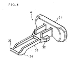
- Fig. 4 is a perspective view of the lock arm 4 engaged with the plug type housing 2 in an inserting state.
- the lock arm 4 has a pulling handle 31, a slide lock 32, an elastic arm 33, a fitting lock portion 34 inwardly directed at the tip of the elastic arm 33, and an engaging lock portion 35 outwardly directed at the tip of the elastic arm 33.
- the fitting lock portion 34 and the engaging lock portion 35 are arranged such that lock acting directions are opposed to each other.
- the slide lock 32 is engaged with stages 23 formed on both sides of the arm receiving space 15.
- the lock arm 4 is slidably engaged by a predetermined clearance ⁇ in the axial direction of the plug type housing 2 by an axial opening shape of this stage 23.
- an engaging projection 24 is formed inwardly at the tip of the enlarging portion 14. Outward deformation of the elastic arm 33 is prevented by engaging the engaging projection 24 with the engaging lock portion 35 of the lock arm 4.
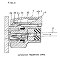
- the clearance ⁇ is widened and a clearance ⁇ is narrowed so that the engaging lock portions 35 of the lock arm 4 and the engaging lock portions 24 of the enlarging portion 14 attain an engaging state.
- the engaging lock portions 24, 35 are engaged, the elastic deformation of the arm 33 is prevented and the fitting of the fitting lock portion 34 is held.
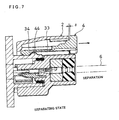
- the clearance ⁇ is narrowed and the clearance ⁇ is widened so that the engaging state of the engaging lock portions 35 of the lock arm 4 and the engaging lock portions 24 of the enlarging portion 14 is released.
- the engaging state of the engaging lock portions 24, 35 is released, the deformation toward the outside of the arm 27 is allowed and the fitting of the fitting lock portion 34 is released.
- the receptacle type housing 3 shown in Fig. 1 is arranged as one portion of a squib holder arranged in a gas generator for expanding an air bag. Electric energy required in ignition is supplied to the squib through pins 41 as two male type terminals.
- This receptacle type housing 3 is formed in a socket which has a base portion 42 projecting the pin 41 and also has a cylindrical portion 43 arranged around the pin 41 and projected from the base portion 42.
- a fitting projection 44 against the fitting lock portion 34 of the lock arm 2, and a convex stripe 45 for positioning fitted to a groove 25 formed in the sleeve portion 12 of the plug type housing 2 are integrally arranged in the outer circumference of the cylindrical portion 43.
- the short circuit insert 5 as a short circuit device is inserted into the sleeve portion 12 forming the socket.
- the short circuit insert 5 has a columnar main body 51 received within the sleeve portion 12 and also has a short circuit grip 52.
- An opening portion 53 opened on the upper face and both side faces is formed in the main body 51 such that the central plug portion 11 of the plug type housing 2 enters the opening portion 53.
- the short circuit grip 52 is integrally formed by an elastic electrically-conductive material and one portion of the tip of the grip 52 is deflected in a direction abutting on both the pins 41, and an electric short circuit is formed in an intermediate portion of the grip 52.
- the two pins 41 are electrically short-circuited as they are in a state in which this short circuit insert 5 is inserted into the receptacle type housing 3.
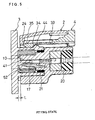
- Fig. 5 is a sectional view showing states of both the connector housings 2, 3 at a fitting state.
- Fig. 6 is a sectional view showing the state of the plug type housing 2 at a separation preventing state.
- Fig. 7 is a sectional view showing the state of the plug type housing 2 at a separating state.
- both the connector housings 2, 3 can be fitted by only pushing-in the lock arm 4 or both the plug type connector housing 2 and the lock arm toward the receptacle type housing 3.
- the electrical short circuit of the male type terminal 41 can be also released at the same time as this fitting.
- the fitting state can be simply visually confirmed by the position relation of both the connector housings 2, 3 in the fitting direction.
- both the connector housings 2, 3 can be hermetically sealed by the seal ring 21 and the rubber plug 20 (see Fig. 5).
- the lock arm 4 for holding the fitting of both the connector housings 2, 3 is arranged such that the lock arm 4 has no influence on the hermetical seal property of both the connectors outside these seal members 20, 21.
- the present invention is not limited to the above embodiment modes, but can be variously designed and changed as long as the invention is described in the claims.
- the male and female relations of both the connector housings 2, 3 may be reversely set.
- the male and female relations of both the terminals 10, 41 may be reversely set.
- the electrical connector is explained when the electrical connector has the short circuit insert.
- the electrical connector having no short circuit insert may also be used.
- the number of terminals is not limited to two, but the electrical connector having three or more terminals arranged in one or plural lines may be also used.
Landscapes
- Details Of Connecting Devices For Male And Female Coupling (AREA)
Description
wherein the above lock arm (4) has a fitting lock portion (34) fitted to the other connector housing (3), and an engaging lock portion (35) engaged with one connector housing (2) in a releasing direction of the above fitting lock portion (34).
Claims (3)
- An electrical connector assembly comprising:characterized in that said lock arm (4) has a fitting lock portion (34) fitted to the other connector housing (3), and an engaging lock portion (35) engaged with one connector housing (2) in a releasing direction of said fitting lockportion (34);a pair of connector housings (2;3) able to be fitted, and a lock arm (4) engaged with one of these connector housings (2) and holding a fitting state of the pair of connector housings (2;3) when said pair of connector housings (2;3) is fitted;
said lock arm (4) is movably arranged in a fitting direction with respect to one connector housing (2), and said engaging lock portion (35) is arranged such that it can be in a engaging posit ion when said lock arm (4) locates in an advancing position with respect to said one connector housing (2) and such that it can be in a releasing position when said lock arm (4) locates in a retreating position with respect to said one connector housing (2);
when only said one connector housing (2) begins to be separated, said lock arm (4) fitted to said other connector housing (3) by said fitting lock portion (34) is left, so that said lock arm (4) locates in the advancing position with respect to said one connector housing (2) and thus said engaging lock portion (35) is in the engaging position whereat it prevents a release of said fitting lock portion (34); and
when said lock arm (4), or both of said one connector housing (2) and said lock arm (4) begin to be separated from said other connector housing (3), said one connector housing (2) and said lock arm (4) are in a mutually movable state so that said lock arm (4) locates in the retreating position with respect to said one connector housing (2) and thus said engaging lock portion (35) is in the releasing position whereat it does not prevent a release of said fitting lock portion (34). - An electrical connector assembly according to claim 1, characterized in that said lock arm has an elastic arm, and said fitting lock portion and said engaging lock portion are arranged at the tip of this elastic arm such that operating directions of the fitting lock portion and the engaging lock portion are opposed to each other.
- A connector comprising:characterized in that:a connector housing (2) which is fitted to a mating side connector (3) and in which a connector position assurance device (4) having an elastic arm (33) for fitting to the mating side connector (3) is engaged,an engaging portion (35) engaged within said connector housing (2) and arranged on a side directed to the exterior of the tip of said elastic arm (33);a fitting portion (34) fitted to the mating side connector (3) is arranged on a side directed to the interior of the tip of said elastic arm (33), and said elastic arm (33) is movably engaged with said connector housing (2) in an axial direction so that said engaging portion (35) is in an engaging position when said elastic arm (33) is in an advancing position in the axial direction and so that said engaging portion (35) is in a disengaging position when said elastic arm (33) is in a retreating position in the axial direction;when only said connector housing (2) begins to be separated, said elastic arm (33) fitted to said mating side connector (3) bysaidfittingportion (34) is left, so that said elastic arm (33) locates in the advancing position in the axial direction to bring said engaging portion (35) into an engaging state, thereby preventing a release of said fitting portion (34); andwhen said elastic arm (33), or both of said connector housing (2) and said elastic arm (33) begin to be separated from said mating side connector (3), said elastic arm (33) locates in the retreating position in the axial direction to bring said engaging portion (35) into the disengaging position, thereby not preventing a release of said fitting portion (34).
Applications Claiming Priority (2)
| Application Number | Priority Date | Filing Date | Title |
|---|---|---|---|
| JP2001207193A JP3607884B2 (en) | 2001-07-09 | 2001-07-09 | Electrical connector assembly and connector used therefor |
| JP2001207193 | 2001-07-09 |
Publications (3)
| Publication Number | Publication Date |
|---|---|
| EP1276180A2 EP1276180A2 (en) | 2003-01-15 |
| EP1276180A3 EP1276180A3 (en) | 2004-01-02 |
| EP1276180B1 true EP1276180B1 (en) | 2005-08-17 |
Family
ID=19043209
Family Applications (1)
| Application Number | Title | Priority Date | Filing Date |
|---|---|---|---|
| EP02291717A Expired - Fee Related EP1276180B1 (en) | 2001-07-09 | 2002-07-09 | Electrical connector assembly and connector used for it |
Country Status (8)
| Country | Link |
|---|---|
| US (1) | US6659789B2 (en) |
| EP (1) | EP1276180B1 (en) |
| JP (1) | JP3607884B2 (en) |
| KR (1) | KR100881499B1 (en) |
| CN (1) | CN1265510C (en) |
| DE (1) | DE60205545T2 (en) |
| HK (1) | HK1051746A1 (en) |
| TW (1) | TW588482B (en) |
Families Citing this family (20)
| Publication number | Priority date | Publication date | Assignee | Title |
|---|---|---|---|---|
| FR2842658A1 (en) * | 2002-07-16 | 2004-01-23 | Radiall Sa | COAXIAL CONNECTOR ELEMENT HOUSING AND COAXIAL CONNECTOR ELEMENT |
| DE10350652B3 (en) * | 2003-10-29 | 2005-06-30 | Yazaki Europe Ltd., Hemel Hempstead | Connector housing with shorting bridge |
| US6896524B1 (en) * | 2004-01-29 | 2005-05-24 | Delphi Technologies, Inc. | Low profile socket connector |
| KR100700732B1 (en) * | 2005-01-04 | 2007-03-27 | 한국단자공업 주식회사 | Connector-housing |
| DE102005013633B4 (en) * | 2005-03-24 | 2012-11-08 | Amphenol-Tuchel Electronics Gmbh | Plug-in system for electrical connectors |
| US7131854B1 (en) * | 2005-08-31 | 2006-11-07 | Lear Corporation | Electrical connector and airbag apparatus having an electrical connector |
| JP4713380B2 (en) * | 2006-03-24 | 2011-06-29 | タイコエレクトロニクスジャパン合同会社 | Waterproof squib connector |
| JP5144404B2 (en) * | 2008-07-04 | 2013-02-13 | 日本圧着端子製造株式会社 | Connector housing |
| JP4784673B2 (en) * | 2009-03-24 | 2011-10-05 | パナソニック電工株式会社 | connector |
| JP5653150B2 (en) * | 2010-09-16 | 2015-01-14 | 矢崎総業株式会社 | Half-mating prevention connector |
| JP5721473B2 (en) | 2011-03-01 | 2015-05-20 | 矢崎総業株式会社 | connector |
| JP5815424B2 (en) * | 2012-01-17 | 2015-11-17 | 矢崎総業株式会社 | Electrical connector |
| US8926355B2 (en) * | 2012-06-29 | 2015-01-06 | Lear Corporation | Connector position assurance device for a connector assembly |
| JP2016012422A (en) * | 2014-06-27 | 2016-01-21 | 住友電装株式会社 | connector |
| JP6245526B2 (en) * | 2014-10-17 | 2017-12-13 | 株式会社オートネットワーク技術研究所 | connector |
| US10355414B1 (en) | 2018-02-08 | 2019-07-16 | Delphi Technologies, Llc | Connector with a connector position assurance device |
| JP6800921B2 (en) * | 2018-08-01 | 2020-12-16 | 矢崎総業株式会社 | connector |
| EP3886264B1 (en) * | 2020-03-27 | 2023-11-08 | Aptiv Technologies Limited | Sealed electrical connector |
| US11594838B2 (en) * | 2020-04-28 | 2023-02-28 | Foxconn (Kunshan) Computer Connector Co., Ltd. | Connector assembly with connector position assurance |
| US11710927B2 (en) * | 2021-06-01 | 2023-07-25 | Lear Corporation | Electrical connector with connector position assurance and mechanical assist |
Family Cites Families (16)
| Publication number | Priority date | Publication date | Assignee | Title |
|---|---|---|---|---|
| JPH0220287U (en) * | 1988-07-27 | 1990-02-09 | ||
| JP2537302B2 (en) | 1990-03-01 | 1996-09-25 | 矢崎総業株式会社 | Lock check device for electrical connector |
| US5120255A (en) * | 1990-03-01 | 1992-06-09 | Yazaki Corporation | Complete locking confirming device for confirming the complete locking of an electric connector |
| JPH0770340B2 (en) * | 1990-03-27 | 1995-07-31 | 矢崎総業株式会社 | Connector coupling detector |
| US5217390A (en) * | 1990-04-16 | 1993-06-08 | Sumitomo Wiring Systems, Ltd. | Connector |
| DE19500959C2 (en) | 1995-01-14 | 1996-11-21 | Amphenol Tuchel Elect | Electrical connector |
| US5681178A (en) | 1995-06-27 | 1997-10-28 | The Whitaker Corporation | Electrical connector with connector position assurance device |
| JP3228854B2 (en) * | 1995-09-21 | 2001-11-12 | 矢崎総業株式会社 | Electrical connector |
| JP3458034B2 (en) * | 1995-12-28 | 2003-10-20 | 矢崎総業株式会社 | Connector mating release mechanism |
| JP3086849B2 (en) * | 1996-08-06 | 2000-09-11 | 矢崎総業株式会社 | Connector mating structure |
| JP3685290B2 (en) * | 1997-07-01 | 2005-08-17 | 住友電装株式会社 | connector |
| US6261115B1 (en) * | 1999-06-11 | 2001-07-17 | Tyco Electronics Logistics Ag | Connector module |
| JP3427743B2 (en) * | 1998-08-20 | 2003-07-22 | 住友電装株式会社 | Mating detection connector |
| JP3817089B2 (en) * | 1999-06-11 | 2006-08-30 | 矢崎総業株式会社 | Half-mating prevention connector |
| JP3741351B2 (en) * | 1999-10-26 | 2006-02-01 | 矢崎総業株式会社 | Half-mating prevention connector |
| JP3508015B2 (en) * | 1999-12-03 | 2004-03-22 | 住友電装株式会社 | connector |
-
2001
- 2001-07-09 JP JP2001207193A patent/JP3607884B2/en not_active Expired - Fee Related
-
2002
- 2002-07-08 KR KR1020020039209A patent/KR100881499B1/en not_active IP Right Cessation
- 2002-07-09 TW TW091115219A patent/TW588482B/en not_active IP Right Cessation
- 2002-07-09 DE DE60205545T patent/DE60205545T2/en not_active Expired - Lifetime
- 2002-07-09 US US10/191,750 patent/US6659789B2/en not_active Expired - Fee Related
- 2002-07-09 EP EP02291717A patent/EP1276180B1/en not_active Expired - Fee Related
- 2002-07-09 CN CNB021405417A patent/CN1265510C/en not_active Expired - Fee Related
-
2003
- 2003-05-30 HK HK03103873A patent/HK1051746A1/en not_active IP Right Cessation
Also Published As
| Publication number | Publication date |
|---|---|
| KR20030007037A (en) | 2003-01-23 |
| CN1265510C (en) | 2006-07-19 |
| EP1276180A2 (en) | 2003-01-15 |
| EP1276180A3 (en) | 2004-01-02 |
| TW588482B (en) | 2004-05-21 |
| KR100881499B1 (en) | 2009-02-05 |
| HK1051746A1 (en) | 2003-08-15 |
| CN1396680A (en) | 2003-02-12 |
| JP2003022876A (en) | 2003-01-24 |
| US6659789B2 (en) | 2003-12-09 |
| DE60205545T2 (en) | 2006-06-08 |
| JP3607884B2 (en) | 2005-01-05 |
| US20030008546A1 (en) | 2003-01-09 |
| DE60205545D1 (en) | 2005-09-22 |
Similar Documents
| Publication | Publication Date | Title |
|---|---|---|
| EP1276180B1 (en) | Electrical connector assembly and connector used for it | |
| US6893277B2 (en) | Squib connector assembly with CPA | |
| US5584712A (en) | Connector | |
| US5573417A (en) | Feeding connector | |
| EP1873871B1 (en) | Electrical connector | |
| EP1097491B1 (en) | Connector for airbag gas generator | |
| JP2978348B2 (en) | Power supply connector | |
| EP0622869B1 (en) | Connector device | |
| US10164371B2 (en) | Waterproof electrical connector with retainer for terminal | |
| US20140315410A1 (en) | Joint connector and assembling method thereof | |
| US7114999B2 (en) | Connector and a connector assembly | |
| US9209561B2 (en) | Connector structure | |
| EP1109263B1 (en) | Electrical connector | |
| JP2003217758A (en) | Electric connector | |
| CN110911891B (en) | Connector structure | |
| US20090098758A1 (en) | Connection system and squib connector therefor | |
| JP2002305052A (en) | Connector | |
| JP2005302715A (en) | Electric plug/socket connector | |
| US7303423B2 (en) | Squib-type electrical connector with multiple engagement means | |
| US11189956B2 (en) | Liquid-tight movable connector | |
| US5984718A (en) | Safety jumper cables | |
| US6461177B1 (en) | Electrical connector | |
| US6929499B2 (en) | Connector and a connector assembly | |
| JPH08287988A (en) | Connector with terminal fall-off preventive means | |
| JPH0878095A (en) | Earth connecting method and earth connecting structure for electric connector |
Legal Events
| Date | Code | Title | Description |
|---|---|---|---|
| PUAI | Public reference made under article 153(3) epc to a published international application that has entered the european phase |
Free format text: ORIGINAL CODE: 0009012 |
|
| AK | Designated contracting states |
Kind code of ref document: A2 Designated state(s): AT BE BG CH CY CZ DE DK EE ES FI FR GB GR IE IT LI LU MC NL PT SE SK TR |
|
| AX | Request for extension of the european patent |
Free format text: AL;LT;LV;MK;RO;SI |
|
| PUAL | Search report despatched |
Free format text: ORIGINAL CODE: 0009013 |
|
| AK | Designated contracting states |
Kind code of ref document: A3 Designated state(s): AT BE BG CH CY CZ DE DK EE ES FI FR GB GR IE IT LI LU MC NL PT SE SK TR |
|
| AX | Request for extension of the european patent |
Extension state: AL LT LV MK RO SI |
|
| 17P | Request for examination filed |
Effective date: 20040624 |
|
| AKX | Designation fees paid |
Designated state(s): DE FR GB |
|
| 17Q | First examination report despatched |
Effective date: 20040818 |
|
| GRAP | Despatch of communication of intention to grant a patent |
Free format text: ORIGINAL CODE: EPIDOSNIGR1 |
|
| GRAS | Grant fee paid |
Free format text: ORIGINAL CODE: EPIDOSNIGR3 |
|
| GRAA | (expected) grant |
Free format text: ORIGINAL CODE: 0009210 |
|
| AK | Designated contracting states |
Kind code of ref document: B1 Designated state(s): DE FR GB |
|
| REG | Reference to a national code |
Ref country code: GB Ref legal event code: FG4D |
|
| REF | Corresponds to: |
Ref document number: 60205545 Country of ref document: DE Date of ref document: 20050922 Kind code of ref document: P |
|
| ET | Fr: translation filed | ||
| PLBE | No opposition filed within time limit |
Free format text: ORIGINAL CODE: 0009261 |
|
| STAA | Information on the status of an ep patent application or granted ep patent |
Free format text: STATUS: NO OPPOSITION FILED WITHIN TIME LIMIT |
|
| 26N | No opposition filed |
Effective date: 20060518 |
|
| PGFP | Annual fee paid to national office [announced via postgrant information from national office to epo] |
Ref country code: DE Payment date: 20100705 Year of fee payment: 9 Ref country code: FR Payment date: 20100713 Year of fee payment: 9 |
|
| PGFP | Annual fee paid to national office [announced via postgrant information from national office to epo] |
Ref country code: GB Payment date: 20100721 Year of fee payment: 9 |
|
| GBPC | Gb: european patent ceased through non-payment of renewal fee |
Effective date: 20110709 |
|
| REG | Reference to a national code |
Ref country code: FR Ref legal event code: ST Effective date: 20120330 |
|
| PG25 | Lapsed in a contracting state [announced via postgrant information from national office to epo] |
Ref country code: FR Free format text: LAPSE BECAUSE OF NON-PAYMENT OF DUE FEES Effective date: 20110801 Ref country code: DE Free format text: LAPSE BECAUSE OF NON-PAYMENT OF DUE FEES Effective date: 20120201 |
|
| REG | Reference to a national code |
Ref country code: DE Ref legal event code: R119 Ref document number: 60205545 Country of ref document: DE Effective date: 20120201 |
|
| PG25 | Lapsed in a contracting state [announced via postgrant information from national office to epo] |
Ref country code: GB Free format text: LAPSE BECAUSE OF NON-PAYMENT OF DUE FEES Effective date: 20110709 |