EP1271505B1 - Single cartridge interface for an automated tape cartridge autoloader/library system - Google Patents
Single cartridge interface for an automated tape cartridge autoloader/library system Download PDFInfo
- Publication number
- EP1271505B1 EP1271505B1 EP02254581A EP02254581A EP1271505B1 EP 1271505 B1 EP1271505 B1 EP 1271505B1 EP 02254581 A EP02254581 A EP 02254581A EP 02254581 A EP02254581 A EP 02254581A EP 1271505 B1 EP1271505 B1 EP 1271505B1
- Authority
- EP
- European Patent Office
- Prior art keywords
- cartridge
- tape
- tape cartridge
- interface
- picker
- Prior art date
- Legal status (The legal status is an assumption and is not a legal conclusion. Google has not performed a legal analysis and makes no representation as to the accuracy of the status listed.)
- Expired - Fee Related
Links
Images


Classifications
-
- G—PHYSICS
- G11—INFORMATION STORAGE
- G11B—INFORMATION STORAGE BASED ON RELATIVE MOVEMENT BETWEEN RECORD CARRIER AND TRANSDUCER
- G11B15/00—Driving, starting or stopping record carriers of filamentary or web form; Driving both such record carriers and heads; Guiding such record carriers or containers therefor; Control thereof; Control of operating function
- G11B15/675—Guiding containers, e.g. loading, ejecting cassettes
- G11B15/68—Automatic cassette changing arrangements; automatic tape changing arrangements
- G11B15/6885—Automatic cassette changing arrangements; automatic tape changing arrangements the cassettes being conveyed within a cassette storage location, e.g. within a storage bin or conveying by belt
Landscapes
- Automatic Tape Cassette Changers (AREA)
Description
- The invention is related to the field of data storage, and in particular, to a single cartridge interface for an automated tape cartridge autoloader/library system.
- A popular device for handling large amounts of information in a data processing system is an automated tape cartridge library. Tape cartridge libraries store and manage large numbers of tape cartridges containing magnetic tape on which data is recorded. Typically, a tape cartridge library is comprised of a plurality of fixed tape cartridge storage locations and at least one read/write tape drive. The tape cartridge storage locations are arranged in predetermined arrays of uniquely identified cells with each cell containing a single tape cartridge. Each of the individual tape cartridges include a computer readable identifying indicia, such as a bar code.
- A tape cartridge retrieval/transport mechanism, known in the art as a "cartridge picker," automatically exchanges the individual tape cartridges between their storage locations and the tape drive. Different types of cartridge pickers are used to accommodate the various tape cartridge arrangements in different tape cartridge library systems. One example of a cartridge picker utilizes a rotatable robotic arm with an optical sensor for selecting and retrieving the correct tape cartridge and transporting the tape cartridge to a tape drive. Another example of a cartridge picker is a linear robotic mechanism that moves along an X-Y translation or about a pivot in a rotary motion to select, retrieve and transport tape cartridges to a tape drive. The tape drive is operable to read/write data from or to the magnetic tape in the tape cartridge, while a host computer that communicates with a library control unit controls operation of the tape library system.
- Some tape cartridge library systems also include a single cartridge interface designed to receive individual tape cartridges from an operator during operation of the library. These single cartridge interfaces also receive tape cartridges ejected from the library system by a cartridge picker.
- Unfortunately, it is a problem in libraries with a single cartridge interface to prevent damage to the cartridge picker and/or tape cartridges. The damage is most often caused by the insertion of tape cartridges through the single cartridge interface when the cartridge picker is not positioned to receive the tape cartridge. Another cause of damage occurs following an ejection operation where the tape cartridge has not been removed from the single cartridge interface and an operator attempts to reinsert the cartridge. In this case, the tape cartridge, while not fully removed from the single cartridge interface, is in an ejected position that permits the cartridge picker to perform additional operations within the library. The cartridge picker and/or the tape cartridge can be seriously damaged if an operator attempts to reinsert the tape cartridge after the cartridge picker has left the single cartridge interface retrieval location.
- US-A-5,537,378 discloses a single cartridge interface which comprises:
- a frame defining a central aperture configured for the exchange of a tape cartridge between a tape cartridge picker and an operator,
- means connected to the frame for coupling with the tape cartridge during ejection of the tape cartridge to permit the removal of the tape cartridge, but which prevent insertion of the cartridge when the tape cartridge picker is not positioned to receive the tape cartridge.
- According to a first aspect of the present invention, there is provided a single cartridge interface for an automated tape cartridge autoloader library system, the single cartridge interface comprising:
- a frame defining a central aperture configured for the exchange of a tape cartridge between a tape cartridge picker connected internal to the autoloader library system and an operator; and
- means connected to the frame for coupling with the tape cartridge during an ejection of the tape cartridge from the single cartridge interface to permit removal of the tape cartridge from the single cartridge interface;
- characterized in that said means is arranged to permit said removal but prevent reinsertion of the tape cartridge into the single cartridge interface before the tape cartridge is removed from the single cartridge interface and when the tape cartridge picker is not positioned to receive the tape cartridge.
- The present invention provides a single cartridge interface for an automated tape cartridge library system, termed "autoloader/library system" herein, that prevents damage to the cartridge picker. Specifically, the present single cartridge interface is configured to prevent the receipt of tape cartridges unless the picker is positioned to receive the tape cartridge. The present single cartridge interface is also configured to prevent the reinsertion of tape cartridges in an ejected position, but not fully removed from the single cartridge interface.
- The autoloader/library system comprises at least one read/write tape drive, a tape cartridge picker, a single tape cartridge interface, and at least one tape cartridge transport magazine. The autoloader/library system is a complete tape cartridge library that stores, manages, and automatically exchanges a plurality of tape cartridges between the tape drive unit, the single cartridge interface, and the at least one tape cartridge transport magazine.
- The present single cartridge interface may comprise a cartridge stop link that cooperates with an interface door and doorstop to control the receipt of tape cartridges in the single cartridge interface. The cartridge stop link mechanically couples to tape cartridges during an ejection operation to prevent a reinsertion of cartridges until the tape cartridge is fully removed from the tape cartridge interface. Once a tape cartridge is removed from the single cartridge interface, the door and doorstop prevent insertion of tape cartridges until the picker is in position to receive cartridges from the single cartridge interface.
- As will become apparent from the following description, a first advantage of the present single cartridge interface is its simple but effective design. A second advantage of the present single cartridge interface is that tape cartridges are not ejected onto the floor, but rather, are retained partially in the interface, while at the same time reinsertion of the cartridge is prevented and the picker is free to perform other operations within the library system. A third advantage of the present single cartridge interface is that the doorstop is only operated during receipt of tape cartridges from an operator, thus lessoning system workload.
- According to a second aspect of the present invention, there is provided a method of operating a single cartridge interface, the method comprising:
- ejecting a tape cartridge partially out of the single cartridge interface to permit operation of a cartridge picker; and
- responsive to ejecting the tape cartridge, coupling a cartridge stop link to the tape cartridge to permit removal of the tape cartridge from the single cartridge interface, but prevent reinsertion of the tape cartridge back into the single cartridge interface when the cartridge picker is not positioned to receive the tape cartridge from the single cartridge interface.
-
- FIG. 1 illustrates an example of a tape cartridge autoloader/library system configured with a single cartridge interface according to the present invention;
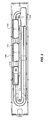
- FIG. 2 illustrates a cross sectional view of a tape cartridge transport magazine for the tape cartridge autoloader/library system;
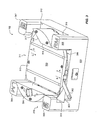
- FIG. 3 illustrates a tape cartridge picker for the tape cartridge autoloader/library system;
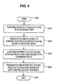
- FIG. 4 is a flow chart illustrating an example of the operation of the tape cartridge autoloader/library system;
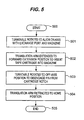
- FIG. 5 is a flow chart illustrating another example of the operation of the tape cartridge autoloader/library system;
- FIG. 6 is a flow chart illustrating another example of the operation of the tape cartridge autoloader/library system;
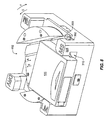
- FIG. 7 is a perspective view of the tape cartridge picker used to illustrate the operation of the tape cartridge autoloader/library system;
- FIG. 8 is another perspective view of the tape cartridge picker used to illustrate the operation of the tape cartridge autoloader/library system;
- FIG. 9 is another perspective view of the tape cartridge picker used to illustrate the operation of the tape cartridge autoloader/library system;
- FIG. 10 is another perspective view of the tape cartridge picker used to illustrate the operation of the tape cartridge autoloader/library system;
- FIG. 11 is another perspective view of the tape cartridge picker used to illustrate the operation of the tape cartridge autoloader/library system;
- FIG. 12 is another perspective view of the tape cartridge picker used to illustrate the operation of the tape cartridge autoloader/library system;
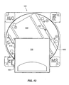
- FIG. 13 is another perspective view of the tape cartridge picker used to illustrate the operation of the tape cartridge autoloader/library system;
- FIG. 14 is another perspective view of the tape cartridge picker used to illustrate the operation of the tape cartridge autoloader/library system;
- FIG. 15 is another perspective view of the tape cartridge picker used to illustrate the operation of the tape cartridge autoloader/library system;
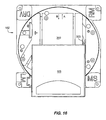
- FIG. 16 is another perspective view of the tape cartridge picker used to illustrate the operation of the tape cartridge autoloader/library system;
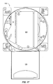
- FIG. 17 is another perspective view of the tape cartridge picker used to illustrate the operation of the tape cartridge autoloader/library system;
- FIG. 18 is a front perspective view of the single cartridge interface according to the present invention;
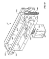
- FIG. 19 is a rear perspective view of the single cartridge interface according to the present invention;
- FIG. 20 is a flow chart illustrating another example of the operation of the tape cartridge autoloader/library system;
- FIG. 21 is a flow chart illustrating another example of the operation of the tape cartridge autoloader/library system;
- FIG. 22 is a perspective view of the single cartridge interface receiving a tape cartridge from an operator;
- FIG. 23 is a perspective view of the single cartridge interface receiving a tape cartridge from the cartridge picker.
- FIG. 24 illustrates a stacked configuration of the autoloader/library system configured with the single cartridge interface.
- For purposes of illustration and not of limitation, various features and advantages of the present single cartridge interface will now be described within the context of an autoloader/library system configured to accommodate a plurality of DLT tape cartridges. It is to be understood that the following description with respect to the example of the autoloader/library system and DLT tape cartridges disclosed herein is not intended to limit the scope of the present invention. It would be obvious to one skilled in the art that the principles of the present invention could easily be applied to other tape libraries, autoloaders, autoloader/library systems and tape cartridge formats.
- Figure 1 depicts an example of an automated tape cartridge autoloader/
library system 100. The primary components of the autoloader/library system 100 are a read/write tape drive 101, atape cartridge picker 102, a singletape cartridge interface 107, and a pair of tape cartridge transport magazines, 103 and 104, enclosed in ahousing 110. The autoloader/library system 100 also comprises acontrol panel 105 that receives control inputs from an operator and includes auser interface 112 to provide status information to the operator. - The autoloader/
library system 100 is a complete tape cartridge library that stores, manages, and automatically exchanges a plurality of tape cartridges, e.g. 106 and 113, between thetape drive 101, thesingle cartridge interface 107, and the tape cartridge transport magazines, 103 and 104. The autoloader/library system 100 could also include multiple tape drives and could be configured to accommodate multiple tape media formats as a matter of design choice by simply incorporating the appropriate tape drive format into the autoloader/library system 100. Some examples of thetape cartridge media 106 include without limitation, DLT, LTO, 8 millimeter, and SDLT tape cartridges. - Advantageously, the autoloader/
library system 100 includes a compact form factor due in large part to thecartridge picker 102 and tapecartridge transport magazines cartridge picker 102 in combination with the transport magazines, 103 and 104, permits a coplanar construction of the autoloader/library system 100 facilitating the compact form factor. In one example of the autoloader/library system 100, thehousing 110 including the tape cartridge transport magazines, 103 and 104, thetape drive 101, thecartridge picker 102, and all control elements including motors, circuitry, and processors, measures approximately 88.9mm (3.5 inches) in height and fits in a standard rack mount. Also, advantageously, the storage and management of the plurality of tape cartridges, e.g. 106 and 113, in the compact form factor of the autoloader/library system 100 is provided by thecartridge picker 102 in combination with the individual tape cartridge transport magazines, 103 and 104. - The tape cartridge transport magazines, 103 and 104, are each configured to receive and store a plurality of individual tape cartridges, e.g. 106, in a plurality of individual tape cartridge storage locations. In one example of the present invention, the tape
cartridge transport magazines - The tape cartridge transport magazines, 103 and 104, are also configured to transport the individual tape cartridges, e.g. 106, in a vertical closed loop within the tape cartridge transport magazines, 103 and 104, so that any one of the stored tape cartridges can be positioned for selection by the
cartridge picker 102. Figure 2 depicts a cross sectional view of the interior of the tapecartridge transport magazine 104 used to illustrate the transportation of the tape cartridges within the tape cartridge transport magazines, 103 and 104. The plurality of tape cartridges are loaded into the tape cartridge transport magazines, 103 and 104, by sliding the individual tape cartridges, e.g. 106, into individual carriages, e.g. 113-116, in a horizontal relationship relative to the magazines, 103 and 104. The tape cartridges, e.g. 106, are transported in themagazine 104 by rotating the carriages 113-116 within the vertical closed loop to the different locations in thetape cartridge magazine 104. - The
cartridge picker 102 is configured to rotate and exchange the individual tape cartridges, e.g. 106, with one of thetape drive 101, themagazine 104, themagazine 103, and thesingle cartridge interface 107. Advantageously, the use of therotating cartridge picker 102 in combination with the transport mechanisms in the magazines, 103 and 104, significantly limits the operation required for a tape cartridge exchange. Thepresent cartridge picker 102 simply rotates between the tape cartridge transport magazines, 103 and 104, thesingle cartridge interface 107, and thetape drive 101, to exchange tape cartridges, e.g. 106. Advantageously, the autoloader/library system 100 provides fast and efficient exchange of tape cartridges between the magazines, 103 and 104, thesingle cartridge interface 107, and thetape drive 101. Also advantageously, the tape cartridges are not flipped or re-oriented during transport within the magazines, 103 and 104, or during exchange with thecartridge picker 102. The tape cartridges, e.g. 106, are always in the proper orientation for retrieval by thecartridge picker 102, and for presentation to thetape drive 101,single cartridge interface 107, and tape cartridge magazines, 103 and 104. - Once selected by the
cartridge picker 102, an individual tape cartridge, e.g. 106, could be provided to one of the following locations depending on the desired operation to be performed. If a read/write operation is desired, thecartridge picker 102 provides the selectedtape cartridge 106 to thetape drive 101. If an ejection operation is desired, thecartridge picker 102 provides the selectedtape cartridge 106 to thesingle cartridge interface 107 for retrieval by an operator. If a load balancing operation is desired, thecartridge picker 102 exchanges thetape cartridge 106 between tapecartridge transport magazine 103 and tapecartridge transport magazine 104. As will become apparent from the following description, thecartridge picker 102 could also provide the selectedtape cartridge 106 to another tape cartridge transport magazine in another coupled tape cartridge autoloader/library system. Finally, thecartridge picker 102 could provide the selected tape cartridge, e.g. 106, to another tape drive in a coupled tape cartridge autoloader/library system. - For purposes of illustration, the
tape cartridge 106 is used throughout the following description of thecartridge picker 102. It should be understood, however, that thecartridge picker 102 could be easily designed according to the principles of the present invention to accommodate numerous tape cartridge formats other than the DLT format of thecartridge 106. - The
cartridge picker 102 comprises atranslation arm 302 and aturntable 300 rotatably connected to astationary base 301. Theturntable 300 includes acentral cavity 316 configured to receive thetape cartridge 106 on theturntable 300. Parallel walls, 313 and 314, and awall 315 integrally formed at a thirty-degree angle to wall 314, define thecentral cavity 316. Alternatively, thewall 315 could be formed at an angle in the range of twenty to forty degrees depending on the geometry of the cartridge. As will become apparent from the following description, the angle of thewall 315 permits thetranslation arm 302 to pass behind thetape cartridge 106 during loading from thesingle cartridge interface 107. Thetranslation arm 302 comprises aperpendicular cartridge pin 303 integrally formed in one end. Thepin 303 is configured to engage or seat in a notch 111 (shown on Figure 1) formed in thetape cartridge 106. - The
cartridge picker 102 also comprises abar code reader 304 for reading computer readable indicia on the tape cartridges. Thebar code reader 304 could be configured in any suitable manner that permits thebar code reader 304 to read the indicia on the tape cartridges. In one example of the present invention, thebar code reader 304 includes a mirror that reflects an image of the indicia on the tape cartridge to thebar code reader 304. Since thecartridge picker 102 rotates, thebar code reader 304 could be located at numerous other locations on thecartridge picker 102 as a matter of design choice. Alternatively, in some applications, thebar code reader 304 could be separate from thepicker 102 and located in the autoloader/library system 100. - The
picker base 301 comprises four vertical columns 305-308 that define four cartridge exchange ports 309-312. As will become apparent from the following description,columns columns translation arm 302 during retrieval and delivery of thetape cartridge 106. Operationally, theturntable 300 rotates within thebase 301 to exchange thetape cartridge 106 with thesingle cartridge interface 107, thetape drive 101 and the tape cartridge transport magazines, 103 and 104, through the exchange ports 309-312. Specifically, theturntable 300 exchanges thetape cartridge 106 with themagazine 103 through theexchange port 309, exchanges thetape cartridge 106 with thesingle cartridge interface 107 through theexchange port 310, exchanges thetape cartridge 106 with themagazine 104 through theexchange port 311, and exchanges thetape cartridge 106 with thetape drive 101 through theexchange port 312. - When the
tape cartridge 106 is exchanged between thecartridge picker 102 and thetape drive 101, or between thecartridge picker 102 and themagazines cartridge 106 is received in thecavity 316 in direction (A) and ejected from thecavity 316 in direction (B) as exemplified in Figure 3. In the context of the present application this is defined as the front of theturntable 300 regardless of the exchange port, e.g. 309, that thepicker 102 is aligned with. Similarly, when thetape cartridge 106 is exchanged between thecartridge picker 102 and thesingle cartridge interface 107, thecartridge 106 is received in thecavity 316 from the opposite end of thecavity 316 in direction (C) and ejected from thecavity 316 in direction (D). In the context of the present application this is defined as the rear of theturntable 300 regardless of the exchange port, e.g. 309, that thepicker 102 is aligned with. As will become apparent from the following description, this permits thecartridge 106 to always be oriented in the same direction when it is located in thecavity 316. - The
translation arm 302 has three primary positions, but as will also become apparent, other positions are used during the exchange of tape cartridges from thetape drive 101, thesingle cartridge interface 107, and themagazines turntable 300 is free to rotate regardless of whether thetape cartridge 106 is present in thecavity 316 or absent from thecavity 316. Additionally, the home position is used regardless of whether thetape cartridge 106 is received from the front or the rear of theturntable 300. The second primary position, shown in Figure 3, is defined as the forward extension position. In the forward extension position, thetranslation arm 302 is ready to engage thetape cartridge 106 and suck thecartridge 106 in the direction (A) from thetape drive 101, or themagazines cavity 316. The third primary position, shown in Figure 8, is defined as the reverse extension position. In the reverse extension position, thetranslation arm 302 is positioned to engage thetape cartridge 106 and suck thecartridge 106 in the direction (C) from thesingle cartridge interface 107 into thecavity 316. - Figure 4 is a flow chart illustrating the operation of the autoloader/
library system 100 during retrieval of thetape cartridge 106 from the tapecartridge transport magazine 103. Those skilled in the art will appreciate that the operation is substantially identical for retrieval of thetape cartridge 106 from the tapecartridge transport magazine 104 and for retrieval of thetape cartridge 106 following an ejection from thetape drive 101. - When one of the tape cartridge transport magazines, 103 or 104, is inserted into the autoloader/
library system 100, the autoloader/library system 100 performs an inventory operation using sensors to determine which carriages, e.g. 113-116, contain tape cartridges and which carriages are empty. In this manner, the autoloader/library system 100 automatically maintains an inventory of loaded tape cartridges during operation. The autoloader/library system 100 also maintains data indicative of the location of specific tape cartridges within the magazines, 103 and 104, so that a desired tape cartridge can be provided to thecartridge picker 102. - On Figure 4 the operation begins at
step 400 with thetranslation arm 302 in the home position of Figure 7. Atstep 401, theturntable 300 is rotated to align off-axis with theexchange port 309, as shown in Figure 9. In the context of the present invention, an off-axis alignment of theturntable 300 is defined as any position of theturntable 300 where either the rear of theturntable 300 or the front of theturntable 300 is not aligned with one of the exchange ports 309-312. Similarly, an on-axis alignment of theturntable 300 is defined as any position of theturntable 300 where either the rear of theturntable 300 or the front of theturntable 300 is aligned with one of the exchange ports 309-312. In this case, the off-axis alignment refers to aligning the front of theturntable 300 approximately three and one half degrees past theexchange port 309 in the direction (E). The off-axis alignment permits extension of thetranslation arm 302 to the forward extension position without contacting thetape cartridge 106. Alternatively, the off-axis alignment could be any position that permits thetranslation arm 302 to be extended to the forward extension position without contacting thetape cartridge 106. - Substantially simultaneously, the
transport magazine 103 transports thecarriage 113 containing the desiredtape cartridge 106 to the storage location aligned with thecartridge picker 102. Atstep 402, thetranslation arm 302 is extended to the forward extension position so that thepin 303 is aligned with thecartridge notch 111 in thetape cartridge 106. Atstep 403 the turntable is rotated three and one half degrees in the direction (F) to align the front of theturntable 300 on-axis with theexchange port 309 and engage or seat thepin 303 in thecartridge notch 111, as shown in Figure 10. Atstep 404, thetranslation arm 302 is retracted to the home position of Figure 7 to suck thetape cartridge 106 into thecavity 316 and onto the central axis of theturntable 300, as shown in Figure 11. The operation ends atstep 405. Advantageously, once in this position, theturntable 300 andcartridge 106 may be freely rotated to deliver thetape cartridge 106 to thetape drive 101, themagazine 104, or thesingle cartridge interface 107. - Figure 5 is a flow chart illustrating the delivery of the
tape cartridge 106 to the tapecartridge transport magazine 104. Those skilled in the art will appreciate that the operation is substantially identical for delivery of thetape cartridge 106 to the tapecartridge transport magazine 103. - On Figure 5, the operation begins at
step 500 with thetape cartridge 106 loaded onto thecartridge picker 102 as described in Figure 4. Atstep 501, theturntable 300 is rotated to align the front of the turntable on-axis with theexchange port 311 and thetape cartridge magazine 104. Substantially simultaneously, thetransport magazine 104 transports an empty carriage, e.g. 114, to the storage location aligned with thecartridge picker 102. Atstep 502, thetranslation arm 302 is extended to the forward extension position to insert thetape cartridge 106 into thecarriage 114 in thetape cartridge magazine 104, as exemplified by the position of thecartridge 106 relative to thepicker 102 in Figure 10. Atstep 503, theturntable 300 is again rotated in the direction (E) to the three and one half degrees off-axis position to disengage thepin 303 from thecartridge notch 111, as exemplified by the position of thecartridge 106 relative to thepin 303 in Figure 9. Atstep 504, the translation arm is retracted to the home position of Figure 7, so that theturntable 300 is free to rotate and perform additional operations. The operation ends atstep 505. - Figure 6 is a flow chart illustrating the delivery of the
tape cartridge 106 to thetape drive 101. On Figure 6, the operation begins atstep 600 with thetape cartridge 106 loaded onto the cartridge picker as described in Figure 4. Atstep 601, theturntable 300 is rotated to align the front of theturntable 300 on-axis with theexchange port 312 and thetape drive 101. Atstep 602, thetranslation arm 302 is extended to the forward extension position to insert thetape cartridge 106 into thetape drive 101, as exemplified by the position of thecartridge 106 relative to thepicker 102 in Figure 10. Those skilled in the art will also appreciate that thetape cartridge 106 is only partially inserted into thetape drive 101 at this point so that thetranslation arm 302 is prevented from contacting thetape drive 101. Atstep 603, theturntable 300 is again rotated in the direction (E) to the three and one half degrees off-axis position to disengage thepin 303 from thecartridge notch 111, as exemplified by the position of thecartridge 106 relative to thepin 303 in Figure 9. Atstep 604, thetranslation arm 302 is retracted to the home position of Figure 7, so that theturntable 300 is free to rotate. Alternatively, thetranslation arm 302 may only be retracted far enough for thepicker 102 to rotate without interference from thecartridge 106. Atstep 605, the turntable is rotated in direction (F) so that it is aligned approximately thirty degrees off-axis with theexchange port 312, and thetranslation arm 302 is behind thetape cartridge 106, as shown in Figure 12. It should be noted that the thirty-degree rotation is not essential but rather advantageously adds mechanical advantage and permits thetranslation arm 302 to push on the center of thecartridge 106. Atstep 606, the translation arm is again extended to the forward extension position to finish inserting thetape cartridge 106 into thetape drive 101. Those skilled in the art will appreciate that because of the thirty-degree off-axis alignment with theexchange port 312, the forward extension of thetranslation arm 302 is now able to complete the insertion of thetape cartridge 106 into thetape drive 101. The operation ends atstep 607. - The primary components of the
single cartridge interface 107 are aframe 1800, acartridge stop link 1802, and adoor 1803. Thedoor 1803 is connected within acentral aperture 1801 in theframe 1800 and pivots both outward and inward as a function of whether thetape cartridge 106 is being ejected from thesingle cartridge interface 107 or inserted into thesingle cartridge interface 107 by an operator. When thetape cartridge 106 is inserted into thesingle cartridge interface 107, thedoor 1803 pivots inward to engage thecartridge stop link 1802 and raise thecartridge stop link 1802 to permit thetape cartridge 106 to pass under thecartridge stop link 1802 and into position for retrieval by thecartridge picker 102. When thetape cartridge 106 is ejected from thesingle cartridge interface 107, thedoor 1803 pivots outward as it is contacted by thetape cartridge 106. - Referring to FIG. 19, the
cartridge stop link 1802 includes a pair of latch members, 1900 and 1901. As will become apparent from the following description, the latch members, 1900 and 1901, prevent thetape cartridge 106 from being reinserted into thesingle cartridge interface 107 following an ejection operation. Thecartridge stop link 1802 is configured to pivot about its ends, 1903 and 1904, when it is contacted by thedoor 1803, but also includes aspring 1902 that biases thecartridge stop link 1802 in the direction A against astop 1908 integrally formed inframe 1800 when not engaged by thedoor 1803. - The
single cartridge interface 107 also includes asolenoid 1905 that controls adoorstop 1906. Thedoorstop 1906 prevents thedoor 1803 from pivoting inward and allowing the insertion of thetape cartridge 106 when thecartridge picker 102 is not in position to receive thetape cartridge 106 from thesingle cartridge interface 107. Aspring 1907 biases thedoor 1803 against thedoorstop 1906 in the closed position when thecartridge 106 is not present in thesingle cartridge interface 107. Advantageously, thedoorstop 1906 is located in a recessedportion 1908 so that thedoorstop 1906 is only retracted during the insertion of thetape cartridge 106 by an operator. During an ejection from thesingle cartridge interface 107, thetape cartridge 106 passes over the recessedportion 1908 without interference from thedoorstop 1906. - Figure 20 is a flow chart illustrating the receipt of the
tape cartridge 106 in thesingle cartridge interface 107 from an operator. On Figure 20, the operation begins atstep 2000. Atstep 2001, the operator provides an input in thecontrol panel 105. The input indicates to the autoloader/library system that thetape cartridge 106 needs to be received from thesingle cartridge interface 107. Atstep 2002, theturntable 300 is rotated in direction (E) to align the rear of theturntable 300 approximately thirty-degrees off-axis with theexchange port 310 and thesingle cartridge interface 107, as shown in Figure 7. It should be noted that atstep 2002, thetranslation arm 302 is in the home position and thewall 315 is aligned with thecolumn 306. Atstep 2003, thesolenoid 1905 is operated to retract thedoorstop 1906 to permit insertion of thetape cartridge 106 through thedoor 1803. Atstep 2004, the operator inserts thetape cartridge 106 through thedoor 1803 and into thesingle cartridge interface 107. During insertion, thedoor 1803 pivots inward and engages thecartridge stop link 1802 raising thecartridge stop link 1802 slightly to permit thetape cartridge 106 to pass under the latch members, 1900 and 1901, as illustrated by Figure 22. - Referring to FIG. 13 the
flex wall 1501 operates to guide thetape cartridge 106 into thecavity 316 during insertion. Specifically, theflex wall 1501 prevents thetape cartridge 106 from rotating counter clockwise into thewall 315 and jamming. As thetape cartridge 106 is inserted into thesingle cartridge interface 107, a key in thewall 315, engages a conventional slot defined in the side of thetape cartridge 106. Advantageously, the key only permits thetape cartridge 106 to be inserted into thesingle cartridge interface 107 in one orientation. - Referring to Figure 14, a cartridge stop/
compression pad 1405 located in the top of thepicker 102 stops the insertion of thetape cartridge 106 when theface 1406 of thetape cartridge 106 contacts aplanar portion 1402 of the cartridge stop/compression pad 1405. In the stopped position, thetape cartridge 106 is positioned so thatpin 303 will align with and engage thecartridge notch 111 when theturntable 300 is rotated. Advantageously, the cartridge stop/compression pad 1405 only functions to stop thetape cartridge 106 when theturntable 300 is in the position of Figures 13 and 14. In all other positions, thetape cartridge 106 contacts abeveled portion 1404 of the cartridge stop/compression pad 1405 causing the cartridge stop/compression pad 1405 to function as a compression pad and expand vertically upward to permit thecartridge 106 to be fully received into thecavity 316. Thus, when thecartridge 106 is retrieved from the transport magazines, 103 and 104, or thetape drive 101, thecartridge picker 102 is able to suck thecartridge 106 past the cartridge stop/compression pad 1405 as the compression pad portion of the cartridge stop/compression pad 1405 expands vertically upward. - In the stopped position of Figure 14, the
corner 1401 of thetape cartridge 106 blocks anemitter 1403 portion of a cartridge present sensor to indicate a cartridge present condition. This permits thecartridge picker 102 to automatically sense thecartridge 106 during insertion from thesingle cartridge interface 107 and begin loading thecartridge 106 into thecavity 316. Alternatively, the loading could begin in response to an input received in thecontrol panel 105 from the operator. - At
step 2005, the translation arm is moved from the home position of Figure 7 to the reverse extension position of Figure 8. Atstep 2006, theturntable 300 is rotated thirty degrees in the direction (F) to the on-axis position to align the rear of theturntable 300 with theexchange port 310 and engage or seat thepin 303 in thecartridge notch 111, as shown in Figure 15. Atstep 2007, thetranslation arm 302 is retracted to the home position of Figure 7, to suck thetape cartridge 106 into thecavity 316 and onto the central axis of theturntable 300. Substantially simultaneously, atstep 2008, thesolenoid 1905 is again operated to release thedoorstop 1906 and thedoor 1803 is closed against thestop 1906 by thedoor spring 1907. The operation ends atstep 2009. Advantageously, thedoorstop 1906 prevents additional tape cartridges from being inserted into thesingle cartridge interface 107 until thepicker 102 is again in position and ready to receive another tape cartridge. - Figure 21 is a flow chart illustrating the delivery of the
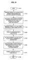
tape cartridge 106 to thesingle cartridge interface 107. On Figure 21, the operation begins atstep 2100 with thetape cartridge 106 loaded onto thecartridge picker 102 as described in Figure 4. Atstep 2101, theturntable 300 is rotated to align the rear of theturntable 300 on-axis with theexchange port 310 and thesingle cartridge interface 107. Atstep 2102, thetranslation arm 302 is extended to the reverse extension position to eject thetape cartridge 106 out of thesingle cartridge interface 107 as exemplified by the position of thecartridge 106 andturntable 300 in FIG. 15. Atstep 2103, theturntable 300 is again rotated in the direction (E) to the thirty-degree off-axis position to disengage thepin 303 from thecartridge notch 111, as shown in Figure 8. Atstep 2104, thetranslation arm 302 is retracted to a position behind thecartridge 106 as shown in Figure 13. Atstep 2105, theturntable 300 is rotated in the direction (F) to the on-axis position so that the rear of the turntable is aligned with theexchange port 310 and thetranslation arm 302 is behind thetape cartridge 106, as shown in Figure 16. Atstep 2106, thetranslation arm 302 is again extended to a reverse extension, as shown in Figure 17, to eject thetape cartridge 106 further out of thesingle cartridge interface 107 so that thecartridge 106 is in theframe 1800 of thesingle cartridge interface 107 as shown in Figure 23. During the ejection, thetape cartridge 106 contacts the beveled portion of the latches, 1900 and 1901, causing thecartridge stop link 1802 to pivot upward and the latches, 1900 and 1901, to slide across the top of thetape cartridge 106. As thecartridge 106 clears thecartridge stop link 1802, thespring 1902 biases thecartridge stop link 1802 in the direction A to secure the latch members, 1900 and 1901, onto the back 2300 of thecartridge 106 as shown in FIG. 23. In this position, thecartridge stop link 1802 prevents the reinsertion of thetape cartridge 106 back into thesingle cartridge interface 107. Thecartridge 106 can only be reinserted by removing thecartridge 106 from thesingle cartridge interface 107 and repeating the steps of figure 20 to recall thepicker 102 and release thedoorstop 1906. Advantageously, thecartridge 106 remains in thesingle cartridge interface 107 for retrieval by the operator and thecartridge picker 102 is free to perform additional operations in the autoloader/library system 100. It should be noted that during the ejection, thedoorstop 1906 in the recessedportion 1908 does not interfere with thetape cartridge 106. Atstep 2107 the translation arm is retracted to home position of Figure 7 and the operation ends atstep 2108. - Figure 24 illustrates multiple autoloader library systems in a stacked configuration. Those skilled in the art will appreciate that an infinite number of autoloader library systems could be stacked although only library systems 100(a) and 100(b) are shown on Figure 24 for clarity.
- The autoloader/
library system 100 is configured to mechanically and electrically interconnect with other substantially identical autoloader/library systems by stacking multiple autoloader/library systems to provide expandability and scalability as a matter of design choice. Once coupled, the multiple autoloader/library systems 100(a) and 100(b) can share individual tape cartridges, e.g. 106, to provide efficient load balancing and performance between the coupled autoloader/library systems. The coupled autoloader/library systems 100(a) and 100(b) could each include acartridge picker 102, tape cartridge transport magazines, 103 and 104, atape drive 101, and asingle cartridge interface 107, or could share elements such as thecartridge picker 102, the single cartridge interface and/or thetape drive 101. Alternatively, asingle cartridge picker 102 configured with an elevator mechanism could serve both autoloader/library systems 100(a) and 100(b). In addition, the coupled autoloader/library systems 100(a) and 100(b) could each include anindividual control panel 105 andinterface 112 or could share a single control panel, e.g. 105, and interface, e.g. 112. In the case where the library systems, e.g. 100, are coupled, thecartridge picker 102 is configured to not only rotate but is also configured to elevate within the multiple library systems, 100(a) and 100(b), to access magazines, 103(a) and 104(b). - In another example, the library systems, 100(a) and 100(b), could share the
single cartridge interface 107. In this case thesingle cartridge interface 107 is configured with an elevator mechanism to transport thesingle cartridge interface 107 in the vertical direction between the multiple library systems, 100(a) and 100(b). Operationally, thecartridge picker 102 in the system 100(a) could pass tape cartridges to thesingle cartridge interface 107. Thesingle cartridge interface 107 then elevates to the system 100(b) where the tape cartridge is automatically passed to a cartridge picker, e.g. 102, in the system 100(b). The cartridge picker in the system 100(b) could then exchange the tape cartridge with the tape drive, e.g. 101 or the magazines, 103(a) and 103(b), in the system 100(b). Cartridges could also be passed from the system 100(b) to the system 100(a) in a similar manner. Thus, the autoloader/library system 100 is customizable to a variety of applications with the capability of expansion at any time to provide both increased capacity and/or increased performance. - The above-described processing systems could be comprised of instructions that are stored on storage media. The instructions can be retrieved and executed by a processor. Some examples of instructions are software, program code, and firmware. Some examples of storage media are memory devices, tape, disks, integrated circuits, and servers. The instructions are operational when executed by the processor to direct the processor to operate in accord with the invention. The term "processor" refers to a single processing device or a group of inter-operational processing devices. Some examples of processors are integrated circuits and logic circuitry. Those skilled in the art are familiar with instructions, processors, and storage media.
- Those skilled in the art can appreciate variations of the above-described embodiments that fall within the scope of the claims. As a result, the invention is not limited to the specific embodiments discussed above.
Claims (8)
- A single cartridge interface (107) for an automated tape cartridge autoloader library system (100), the single cartridge interface (107) comprising:a frame (1800) defining a central aperture (1801) configured for the exchange of a tape cartridge (106) between a tape cartridge picker (102) connected internal to the autoloader library system and an operator; andmeans (1802, 1900, 1901) connected to the frame (1800) for coupling with the tape cartridge (106) during an ejection of the tape cartridge from the single cartridge interface (107) to permit removal of the tape cartridge from the single cartridge interface;wherein said means (1802, 1900, 1901) is arranged to permit said removal but prevent reinsertion of the tape cartridge (106) into the single cartridge interface (107) before the tape cartridge (106) is removed from the single cartridge interface (107) and when the tape cartridge picker (102) is not positioned to receive the tape cartridge (106).
- The single cartridge interface of claim 1 comprising:means (1803, 1906) for preventing insertion of tape cartridges (106) into the single cartridge interface (107) when the cartridge picker (102) is not positioned to receive the tape cartridge.
- The single cartridge interface of claim 2 wherein the means for preventing insertion of the tape cartridges includes:a door (1803) pivotally connected to the frame (1800) within the central aperture (1801); anda doorstop (1906) configured to cooperate with the door (1803) to prevent the insertion of the tape cartridges (106) into the single cartridge interface (107) when the cartridge picker (102) is not positioned to receive the tape cartridges.
- The single cartridge interface of claim 1 wherein the means (1802, 1900, 1901) for coupling to the tape cartridge (106) during the ejection of the tape cartridge includes a cartridge stop link (1802) pivotally connected to the frame (1800).
- The single cartridge interface of claim 4 wherein the means (1802, 1900, 1901) for coupling to the tape cartridge (106) during the ejection of the tape cartridge includes at least one latch member (1900, 1901) integrally formed in the cartridge stop link (1802) and configured to couple to the tape cartridge (106) during the ejection of the tape cartridge.
- The single cartridge interface of claim 4 wherein the means (1802, 1900, 1901) for coupling to the tape cartridge (106) during the ejection of the tape cartridge includes a pair of latch members (1900, 1901) integrally formed in the cartridge stop link (1802) and configured to couple to the tape cartridge (106) during the ejection of the tape cartridge.
- A method of operating a single cartridge interface (107), the method comprising:ejecting a tape cartridge (106) partially out of the single cartridge interface (107) to permit operation of a cartridge picker (102); andresponsive to ejecting the tape cartridge (106), coupling a cartridge stop link (1802) to the tape cartridge (106) to permit removal of the tape cartridge from the single cartridge interface (107), but prevent reinsertion of the tape cartridge (106) back into the single cartridge interface when the cartridge picker (102) is not positioned to receive the tape cartridge from the single cartridge interface and before the tape cartridge (106) is removed from the single cartridge interface (107).
- The method of claim 7 the method comprising:preventing insertion of the tape cartridge (106) into the single cartridge interface (107) when the cartridge picker (102) is not positioned to receive the tape cartridge from the single cartridge interface.
Applications Claiming Priority (2)
| Application Number | Priority Date | Filing Date | Title |
|---|---|---|---|
| US896907 | 1997-07-18 | ||
| US09/896,907 US6606218B2 (en) | 2000-11-10 | 2001-06-28 | Single tape cartridge interface having a cartridge reinsertion preventing mechanism in an automated autoloader/library system |
Publications (3)
| Publication Number | Publication Date |
|---|---|
| EP1271505A2 EP1271505A2 (en) | 2003-01-02 |
| EP1271505A3 EP1271505A3 (en) | 2003-03-12 |
| EP1271505B1 true EP1271505B1 (en) | 2006-12-13 |
Family
ID=25407046
Family Applications (1)
| Application Number | Title | Priority Date | Filing Date |
|---|---|---|---|
| EP02254581A Expired - Fee Related EP1271505B1 (en) | 2001-06-28 | 2002-06-28 | Single cartridge interface for an automated tape cartridge autoloader/library system |
Country Status (4)
| Country | Link |
|---|---|
| US (1) | US6606218B2 (en) |
| EP (1) | EP1271505B1 (en) |
| JP (1) | JP4106244B2 (en) |
| DE (1) | DE60216669T2 (en) |
Families Citing this family (4)
| Publication number | Priority date | Publication date | Assignee | Title |
|---|---|---|---|---|
| JP2007035234A (en) * | 2005-06-24 | 2007-02-08 | Mitsumi Electric Co Ltd | Tape cartridge auto-loader |
| JP2007080436A (en) * | 2005-09-15 | 2007-03-29 | Mitsumi Electric Co Ltd | Tape cartridge auto-loader |
| JP2007080439A (en) * | 2005-09-15 | 2007-03-29 | Mitsumi Electric Co Ltd | Tape cartridge autoloader |
| JP4391984B2 (en) * | 2005-12-19 | 2009-12-24 | 富士通株式会社 | Cable transport mechanism and library device |
Family Cites Families (35)
| Publication number | Priority date | Publication date | Assignee | Title |
|---|---|---|---|---|
| US4063294A (en) | 1975-08-22 | 1977-12-13 | Northwestern Technology, Inc. | Tape cartridge loading mechanism |
| US4981409A (en) | 1985-04-16 | 1991-01-01 | Canon Kabushiki Kaisha | Cartridge auto changer |
| JPS62134852A (en) | 1985-12-09 | 1987-06-17 | Hitachi Ltd | Cartridge loading system |
| JPS62239372A (en) | 1986-04-08 | 1987-10-20 | Sony Corp | Automatic cassette changer |
| DE3721821C1 (en) | 1986-07-04 | 1988-10-27 | Neumann Christian G Von | Video cassette tape replay device for optionally replaying video cassettes |
| US4910619A (en) | 1987-09-16 | 1990-03-20 | Sony Corporation | Automatic changing system for cassette-type mediums |
| US4835634A (en) | 1988-02-24 | 1989-05-30 | Storage Technology Corporation | Automatic magnetic tape cartridge stack loader for tape drive systems |
| DE68917620T2 (en) | 1988-03-23 | 1995-04-20 | Sony Corp | Automatic video cassette changer. |
| EP0426456B1 (en) | 1989-10-31 | 1996-05-15 | Sanki Engineering Co. Ltd. | Automatic storage installation for information recording media |
| US5469310A (en) | 1989-11-13 | 1995-11-21 | Wangdat, Inc. | Automated cassette loader |
| US5089920A (en) * | 1989-11-13 | 1992-02-18 | Wangdat, Inc. | Loader mechanism for tape cartridge systems |
| DE69025717T2 (en) * | 1989-12-07 | 1996-10-17 | Victor Company Of Japan | Cassette loading device for video cassette recorder |
| JP3208787B2 (en) | 1991-06-17 | 2001-09-17 | ソニー株式会社 | Cassette transfer device |
| JP3276986B2 (en) | 1992-06-29 | 2002-04-22 | 日本電産コパル株式会社 | Open / close door mechanism |
| JPH0652657A (en) | 1992-07-30 | 1994-02-25 | Hitachi Electron Eng Co Ltd | Bar code reading system of magnetic tape |
| GB2271014B (en) | 1992-09-29 | 1996-01-24 | M4 Data Ltd | Tape drive machine with tape cartridge magazine |
| US5430588A (en) * | 1993-02-25 | 1995-07-04 | Wangdat, Inc. | Method and apparatus for latching an access door of a magazine loading tape drive |
| US5537378A (en) | 1993-08-25 | 1996-07-16 | Clarion Co., Ltd. | Data processing device with controlled insertion of recording media |
| US5680377A (en) | 1993-11-03 | 1997-10-21 | International Business Machines Corporation | Automated data storage library employing multi-direction picker with double lip gripper |
| US5449091A (en) | 1994-03-18 | 1995-09-12 | Storage Technology Corporation | Carousel apparatus for handling data storage cartridges |
| US5555143A (en) | 1995-01-17 | 1996-09-10 | Western Automation Laboratories, Inc. | Data cartridge library system architecture |
| JP3470438B2 (en) | 1995-02-03 | 2003-11-25 | ソニー株式会社 | Autoloader for tape cartridges |
| US5856894A (en) | 1995-10-26 | 1999-01-05 | Media Logic, Inc. | Data storage and retrieval system having a data cartridge conveyor with independently operable drives each with an associated cartridge transfer mechanism |
| US5847897A (en) | 1995-10-26 | 1998-12-08 | Media Logic, Inc. | Data storage and retrieval system having plural data cartridges, plural drive mechanisms each with an associated transfer mechanism having a finger member to fully insert a cartridge into its associated drive |
| US5760995A (en) | 1995-10-27 | 1998-06-02 | Quantum Corporation | Multi-drive, multi-magazine mass storage and retrieval unit for tape cartridges |
| US5973876A (en) * | 1996-05-14 | 1999-10-26 | Storage Technology Corportion | Data cartridge shuttle mechanism and method of operating the same |
| US5959803A (en) | 1996-07-12 | 1999-09-28 | Hitachi, Ltd. | Cartridge changer, data storage unit using the changer and apparatus using the data storage unit |
| US5752668A (en) | 1996-09-16 | 1998-05-19 | Philips Electronics North America Corporation | Tape library cartridge manipulation gripper with z-axis translation |
| US5746385A (en) | 1996-09-16 | 1998-05-05 | Philips Electronics North America Corporation | Tape library cartridge storage and control system |
| US5975450A (en) | 1996-09-16 | 1999-11-02 | Plasmon Lms, Inc. | Tape library cartridge manipulation x-y positioning system |
| US5999356A (en) | 1997-08-29 | 1999-12-07 | International Business Machines Corporation | Data cartridge library with rotating storage stacks |
| US6130800A (en) | 1998-07-08 | 2000-10-10 | Storage Technology Corporation | Data storage library with cartridge access mechanism |
| IT1308807B1 (en) | 1999-04-16 | 2002-01-11 | Gv Di Bragadin Luigi S A S | AUTOMATIC DISTRIBUTOR OF AUDIO PRODUCTS, SUCH AS VIDIOCASSETTES, CDS AND SIMILAR. |
| US6754037B1 (en) | 1999-07-28 | 2004-06-22 | Storage Technology Corporation | Small library horseshoe architecture |
| US6381089B1 (en) | 2000-07-28 | 2002-04-30 | Qualstar Corporation | Tape cassette storage and accessing system with closely spaced layered cassettes |
-
2001
- 2001-06-28 US US09/896,907 patent/US6606218B2/en not_active Expired - Lifetime
-
2002
- 2002-06-28 EP EP02254581A patent/EP1271505B1/en not_active Expired - Fee Related
- 2002-06-28 JP JP2002189180A patent/JP4106244B2/en not_active Expired - Fee Related
- 2002-06-28 DE DE60216669T patent/DE60216669T2/en not_active Expired - Fee Related
Also Published As
| Publication number | Publication date |
|---|---|
| EP1271505A2 (en) | 2003-01-02 |
| DE60216669D1 (en) | 2007-01-25 |
| EP1271505A3 (en) | 2003-03-12 |
| DE60216669T2 (en) | 2007-10-18 |
| JP4106244B2 (en) | 2008-06-25 |
| US6606218B2 (en) | 2003-08-12 |
| JP2003109268A (en) | 2003-04-11 |
| US20020057520A1 (en) | 2002-05-16 |
Similar Documents
| Publication | Publication Date | Title |
|---|---|---|
| EP1278190B1 (en) | Tape cartridge transport magazine for an automated tape cartridge autoloader/library system | |
| JP3565273B2 (en) | Storage library with horseshoe structure | |
| EP2189982B1 (en) | Housing cell, and magazine | |
| US6816331B2 (en) | Tape cartridge picker for an automated tape cartridge autoloader/library system | |
| JP2004241119A (en) | Auto-changer | |
| EP1271504B1 (en) | Compact form factor for an automated tape cartridge autoloader/library system | |
| EP1205927B1 (en) | Automated tape cartridge autoloader/library system | |
| US6985328B2 (en) | One and three quarters inch form factor tape cartridge autoloader | |
| US7823173B2 (en) | Removable disk media including holographic optical disk stacked in a tape cartridge shell | |
| EP1271505B1 (en) | Single cartridge interface for an automated tape cartridge autoloader/library system | |
| US6538841B2 (en) | Cartridge stop/compression pad for a tape cartridge picker | |
| GB2345375A (en) | Data storage unit incorporating an autochanger for data storage media stored within a removable magazine | |
| US20040179293A1 (en) | Adapter for a tape cartridge bay | |
| US5325249A (en) | Differentiation of media types via leader block characteristics | |
| EP1320092B1 (en) | Cartridge orientation apparatus for cartridge storage magazines and method |
Legal Events
| Date | Code | Title | Description |
|---|---|---|---|
| PUAI | Public reference made under article 153(3) epc to a published international application that has entered the european phase |
Free format text: ORIGINAL CODE: 0009012 |
|
| AK | Designated contracting states |
Kind code of ref document: A2 Designated state(s): AT BE CH CY DE DK ES FI FR GB GR IE IT LI LU MC NL PT SE TR |
|
| AX | Request for extension of the european patent |
Free format text: AL;LT;LV;MK;RO;SI |
|
| PUAL | Search report despatched |
Free format text: ORIGINAL CODE: 0009013 |
|
| AK | Designated contracting states |
Kind code of ref document: A3 Designated state(s): AT BE CH CY DE DK ES FI FR GB GR IE IT LI LU MC NL PT SE TR Designated state(s): AT BE CH CY DE DK ES FI FR GB GR IE IT LI LU MC NL PT SE TR |
|
| AX | Request for extension of the european patent |
Extension state: AL LT LV MK RO SI |
|
| 17P | Request for examination filed |
Effective date: 20030819 |
|
| AKX | Designation fees paid |
Designated state(s): DE FR GB |
|
| 17Q | First examination report despatched |
Effective date: 20040423 |
|
| GRAC | Information related to communication of intention to grant a patent modified |
Free format text: ORIGINAL CODE: EPIDOSCIGR1 |
|
| GRAP | Despatch of communication of intention to grant a patent |
Free format text: ORIGINAL CODE: EPIDOSNIGR1 |
|
| GRAS | Grant fee paid |
Free format text: ORIGINAL CODE: EPIDOSNIGR3 |
|
| GRAA | (expected) grant |
Free format text: ORIGINAL CODE: 0009210 |
|
| AK | Designated contracting states |
Kind code of ref document: B1 Designated state(s): DE FR GB |
|
| REG | Reference to a national code |
Ref country code: GB Ref legal event code: FG4D |
|
| REF | Corresponds to: |
Ref document number: 60216669 Country of ref document: DE Date of ref document: 20070125 Kind code of ref document: P |
|
| ET | Fr: translation filed | ||
| PLBE | No opposition filed within time limit |
Free format text: ORIGINAL CODE: 0009261 |
|
| STAA | Information on the status of an ep patent application or granted ep patent |
Free format text: STATUS: NO OPPOSITION FILED WITHIN TIME LIMIT |
|
| 26N | No opposition filed |
Effective date: 20070914 |
|
| GBPC | Gb: european patent ceased through non-payment of renewal fee |
Effective date: 20070628 |
|
| REG | Reference to a national code |
Ref country code: FR Ref legal event code: ST Effective date: 20080229 |
|
| PG25 | Lapsed in a contracting state [announced via postgrant information from national office to epo] |
Ref country code: DE Free format text: LAPSE BECAUSE OF NON-PAYMENT OF DUE FEES Effective date: 20080101 |
|
| PG25 | Lapsed in a contracting state [announced via postgrant information from national office to epo] |
Ref country code: GB Free format text: LAPSE BECAUSE OF NON-PAYMENT OF DUE FEES Effective date: 20070628 |
|
| PG25 | Lapsed in a contracting state [announced via postgrant information from national office to epo] |
Ref country code: FR Free format text: LAPSE BECAUSE OF NON-PAYMENT OF DUE FEES Effective date: 20070702 |