EP1271178A2 - Système de positionnement pour réseaux téléphoniques numériques - Google Patents
Système de positionnement pour réseaux téléphoniques numériques Download PDFInfo
- Publication number
- EP1271178A2 EP1271178A2 EP02100398A EP02100398A EP1271178A2 EP 1271178 A2 EP1271178 A2 EP 1271178A2 EP 02100398 A EP02100398 A EP 02100398A EP 02100398 A EP02100398 A EP 02100398A EP 1271178 A2 EP1271178 A2 EP 1271178A2
- Authority
- EP
- European Patent Office
- Prior art keywords
- receivers
- received
- signals
- transmission
- time
- Prior art date
- Legal status (The legal status is an assumption and is not a legal conclusion. Google has not performed a legal analysis and makes no representation as to the accuracy of the status listed.)
- Granted
Links
Images


Classifications
-
- G—PHYSICS
- G01—MEASURING; TESTING
- G01S—RADIO DIRECTION-FINDING; RADIO NAVIGATION; DETERMINING DISTANCE OR VELOCITY BY USE OF RADIO WAVES; LOCATING OR PRESENCE-DETECTING BY USE OF THE REFLECTION OR RERADIATION OF RADIO WAVES; ANALOGOUS ARRANGEMENTS USING OTHER WAVES
- G01S5/00—Position-fixing by co-ordinating two or more direction or position line determinations; Position-fixing by co-ordinating two or more distance determinations
- G01S5/02—Position-fixing by co-ordinating two or more direction or position line determinations; Position-fixing by co-ordinating two or more distance determinations using radio waves
- G01S5/14—Determining absolute distances from a plurality of spaced points of known location
-
- G—PHYSICS
- G01—MEASURING; TESTING
- G01S—RADIO DIRECTION-FINDING; RADIO NAVIGATION; DETERMINING DISTANCE OR VELOCITY BY USE OF RADIO WAVES; LOCATING OR PRESENCE-DETECTING BY USE OF THE REFLECTION OR RERADIATION OF RADIO WAVES; ANALOGOUS ARRANGEMENTS USING OTHER WAVES
- G01S5/00—Position-fixing by co-ordinating two or more direction or position line determinations; Position-fixing by co-ordinating two or more distance determinations
- G01S5/0009—Transmission of position information to remote stations
- G01S5/0018—Transmission from mobile station to base station
- G01S5/0036—Transmission from mobile station to base station of measured values, i.e. measurement on mobile and position calculation on base station
-
- G—PHYSICS
- G01—MEASURING; TESTING
- G01S—RADIO DIRECTION-FINDING; RADIO NAVIGATION; DETERMINING DISTANCE OR VELOCITY BY USE OF RADIO WAVES; LOCATING OR PRESENCE-DETECTING BY USE OF THE REFLECTION OR RERADIATION OF RADIO WAVES; ANALOGOUS ARRANGEMENTS USING OTHER WAVES
- G01S5/00—Position-fixing by co-ordinating two or more direction or position line determinations; Position-fixing by co-ordinating two or more distance determinations
- G01S5/02—Position-fixing by co-ordinating two or more direction or position line determinations; Position-fixing by co-ordinating two or more distance determinations using radio waves
- G01S5/10—Position of receiver fixed by co-ordinating a plurality of position lines defined by path-difference measurements, e.g. omega or decca systems
-
- H—ELECTRICITY
- H04—ELECTRIC COMMUNICATION TECHNIQUE
- H04W—WIRELESS COMMUNICATION NETWORKS
- H04W64/00—Locating users or terminals or network equipment for network management purposes, e.g. mobility management
-
- G—PHYSICS
- G01—MEASURING; TESTING
- G01S—RADIO DIRECTION-FINDING; RADIO NAVIGATION; DETERMINING DISTANCE OR VELOCITY BY USE OF RADIO WAVES; LOCATING OR PRESENCE-DETECTING BY USE OF THE REFLECTION OR RERADIATION OF RADIO WAVES; ANALOGOUS ARRANGEMENTS USING OTHER WAVES
- G01S1/00—Beacons or beacon systems transmitting signals having a characteristic or characteristics capable of being detected by non-directional receivers and defining directions, positions, or position lines fixed relatively to the beacon transmitters; Receivers co-operating therewith
- G01S1/02—Beacons or beacon systems transmitting signals having a characteristic or characteristics capable of being detected by non-directional receivers and defining directions, positions, or position lines fixed relatively to the beacon transmitters; Receivers co-operating therewith using radio waves
- G01S1/022—Means for monitoring or calibrating
- G01S1/024—Means for monitoring or calibrating of beacon transmitters
-
- G—PHYSICS
- G01—MEASURING; TESTING
- G01S—RADIO DIRECTION-FINDING; RADIO NAVIGATION; DETERMINING DISTANCE OR VELOCITY BY USE OF RADIO WAVES; LOCATING OR PRESENCE-DETECTING BY USE OF THE REFLECTION OR RERADIATION OF RADIO WAVES; ANALOGOUS ARRANGEMENTS USING OTHER WAVES
- G01S1/00—Beacons or beacon systems transmitting signals having a characteristic or characteristics capable of being detected by non-directional receivers and defining directions, positions, or position lines fixed relatively to the beacon transmitters; Receivers co-operating therewith
- G01S1/02—Beacons or beacon systems transmitting signals having a characteristic or characteristics capable of being detected by non-directional receivers and defining directions, positions, or position lines fixed relatively to the beacon transmitters; Receivers co-operating therewith using radio waves
- G01S1/04—Details
- G01S1/045—Receivers
Definitions
- the present invention relates to a positioning system for use with digital telephone networks such as a GSM network.
- EP-A-0 303 371 the contents of which are hereby incorporated by reference, describes a radio navigation and tracking system which makes use of independent radio transmitters set up for other purposes.
- the signals from each transmitter, taken individually, are received by two receiving stations, one at a fixed and known location, and the other mounted on the mobile object whose position is to be determined.
- a representation of the signals received at one receiving station is sent via a link to a processor at the other receiving station, where the received signals are compared to find their phase differences or time delays.
- Three such measurements, made on three widely spaced independent transmitters, are sufficient to determine the position of the mobile receiver in two dimensions, i.e. its position on the ground.
- the phase or time offset between the master oscillators in the two receivers is also determined.
- WO-A-94-28432 shows how this same system may be applied to radio positioning inside tunnels, underground car parks, or other shielded spaces.
- WO-A-97-11384 these ideas are extended further and applied specifically to GSM and other digital telephone networks, for example CDMA, UMTS, or satellite-based systems (the latter providing the possibility of measuring height as well as position on the ground).
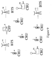
- the system known as CURSOR, uses the signals from the network transmitters for positioning purposes (see Figure 1).
- a short burst of the signals from one such transmitter (known as a Base Transceiver Station, BTS) are received by a mobile handset (known as the CURSOR Rover Unit, CRU) whose position is to be determined, where they are converted to baseband, digitised, and recorded in memory.
- BTS Base Transceiver Station
- CRU CURSOR Rover Unit
- the same burst is also received by another receiver (CURSOR Base Unit, CBU) at a fixed and known location, converted likewise to baseband, digitised and recorded.
- CURSOR Base Unit CBU
- CPP CURSOR position processor
- the corresponding sets are compared, for example using a cross-correlation procedure, to find the time delays between them.
- the three sets of recordings produce three time delays, from which the position of the CRU can be found relative to the (known) positions of the BTSs and the known position of the CBU.
- BCCH Broadcast Control Channel
- the present invention is intended to overcome this disadvantage by making the recordings in a different fashion, and by exploiting the special characteristics of digital telephone signals.
- the quantity of data needing to be transferred may be reduced dramatically, making it fit easily, for example, into one SMS packet.
- the measurements by the CRU can be made entirely during the handset's idle time, so that there is no delay when the user wishes to make a call, and giving a better position solution based on a longer averaging of the received signals.
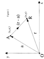
- ⁇ t a (
- ⁇ is the speed of the radio waves
- ⁇ is the clock time offset between the clocks in the receivers at O and R.
- ⁇ t b (
- ⁇ t c (
- ⁇ t a , ⁇ t b , ⁇ t c are measured by the methods disclosed in WO-A-97-11384 and the values of a , b , c , and ⁇ are known, and hence the equations can be solved to find the position of the handset, r .
- ⁇ ab (
- ⁇ t ab1 is the time offset of the received signals from BTSs A & B as determined from the cross-correlation.
- ⁇ t bc1 (
- ⁇ t ab2 (
- )/ ⁇ + ⁇ ab and ⁇ t bc2 (
- ⁇ t ab1 and ⁇ t bc1 have been measured at the CRU as described above, and the values of ⁇ t ab2 and ⁇ t bc2 have been measured at the CBU.
- the values of a, b, c, and ⁇ are known and hence the position, r, of the CRU can be deduced using standard mathematical methods.
- ⁇ , ⁇ ab , and ⁇ bc have all disappeared from equations (4). This is because we have made the assumption that the measurements by the CRU and CBU are either performed simultaneously, or sufficiently close together that there is no significant drift between them.
- TDMA time division multiple access
- Each time slot carries 156.25 bits at a rate of about 271 kbits s -1 and may, for example, represent a 'normal burst' of data and training bits, a 'frequency correction burst' (FCB) of fixed pattern, a 'synchronisation burst' (SCH) of data and training bits, or an 'access burst' with a synchronisation sequence and data.
- Each of these bursts also carries header, tail, and guard bits. How many of the time slots are being used at any moment in a given frame depends on the way the system has been set up and on the amount of traffic at that moment. However, even in quiet conditions the BCCH logical channel will be broadcasting one access burst in every frame. Furthermore, these frames are numbered with a repeat period of several hours. We can therefore use the arrival of a given frame number to synchronise the start of the recordings made by the CRU and CBU.
- time offsets between the oscillators controlling the BTS transmissions, and the time offsets between the oscillators in the two receivers vary slowly with time, and can thus be modelled by a linear fit or low-order polynomial over short periods.
- Most crystal oscillators exhibit stabilities of one part in 10 6 or better over short periods.
- At least two receivers of a digital telephone network position determining system a first of which is at a known location and a second of which is located on a mobile unit whose position is to be determined, which system utilises transmission signals having a format at least a portion of which has predetermined values, in which the relative time offsets of the transmission signals received at each receiver from a number of transmission sources are measured relative to each other by comparing, for example by cross-correlating, the received transmission signals from the different transmission sources with one another to determine their relative time offsets and thereby determine the position of the second receiver by determining the time delay between the respective signals received at both receiving stations.
- the invention includes both the system and a position determining method.
- At least two receivers of a position determining system a first of which is at a known location and a second of which is located on a mobile unit whose position is to be determined, which system utilises transmission signals having a format at least a portion of which is sequentially repeated, in which the relative time offsets of the transmission signals received at each receiver from a number of transmission sources are measured relative to each other by comparing, for example by cross-correlating, the sequentially received transmission signals from the different transmission sources with one another to determine their relative time offsets and thereby determine the position of the second receiver by determining the time delay between the respective signals received at both receiving stations.
- the transmission sources are preferably the base transceiver stations and the mobile receiver may be a digital handset.
- the reference signals provide, in effect, templates which can be matched with the transmission signals. Using the fact that the signals are formatted in the same way and thus have identical portions allows them to be matched (e.g. cross-correlated), and the amount in time by which a recording of one has to be moved relative to the other in order to match, provides an estimate of the time offset.
- Knowing the time offsets enables the relative received time offsets between the different transmission source signals to be calculated, and hence the position of the mobile to be determined as described in more detail below.
- the time offsets can be measured using locally-created templates in a GSM telephone system, for example in the following manner.
- the CRU has recorded a short burst of the signals from BTS A. Contained within that recording is the framing structure and other 'given' data (or predetermined values) described above which is a constant feature of those transmissions.
- the processor within the CRU can create a matching template, based on the known structure of the network signals, and can ignore those parts where the exact form of the received data is not known.
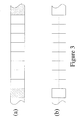
- Such a template is shown by way of example in Figure 3.
- the shaded portions of the transmitted signals, shown at (a) are exactly specified by the network protocol (the frame structure etc.). These can be matched by the locally-generated template, shown at (b).
- the unshaded portions of (a) cannot be predicted in advance, and so these parts are not used in the correlation.
- the correlation peak corresponds to the time offset, i.e. the time offset between the received signals and the local clock inside the CRU.
- ⁇ t a1 (
- ⁇ a is the time offset of the BTS transmissions
- ⁇ 1 is the time offset of the CRU's internal clock, both relative to a mythical universal 'absolute' clock.
- )/ ⁇ + ⁇ b + ⁇ 1 and ⁇ t c1 (
- ⁇ t a2 (
- ⁇ t b2 (
- ⁇ t c2 (
- a CURSOR system which operates in exactly the same way as that described in WO-A-97-11384, with the same characteristics of accuracy, speed etc. The differences lie in the manner in which the measurements are made and in the content of the data sent over the links to the CPP.
- the time offsets are determined by the CPP from the raw data recorded by both CRU and CBU. According to the invention of the present application, the time offsets are determined locally, requiring much less data to be sent. Note, too, that in this system the relative transmission delays of the signals transmitted from the different BTSs are not measured and are never used in the computation.
- the geometry of the calculation is based on the intersection of circles centred on the positions of the BTSs. This is very different from other systems in which the equivalent of the CBU measures the relative transmission delays and transmits them to the processing unit which then performs a standard calculation based on the intersection of hyperbolae.
- the above description shows how the use of a single locally-generated template can be used to estimate the time offsets.
- the template can be generated from the known characteristics of the network signals, as described above, or it can be measured using the signals, say, from the first received channel as the template for correlating with the other channels. It may sometimes be advantageous to use more than one template in the estimation process, especially when the received signals are distorted, for example by the effects of multipath propagation.
- the best template from the point of view of maximising the correlation is one which matches exactly the received signals.
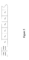
- the estimate of the time offset so obtained may contain a systematic bias which can be shown up by using different templates. This is illustrated in Figure 4 where the transmitted profile is shown at (a), and the received profile (somewhat idealised) is shown at (b).
- a range of templates corresponding to different amounts of multipath, shown at (c1), (c2) etc., can be matched to the received data, and the one giving the closest match provides an estimate of the multipath delay.
- a GSM CURSOR positioning system has a fixed CBU constantly cycling through the BCCHs from the surrounding BTSs and measuring the time offsets between them and the template locked to the internal clock. Its local processor maintains a low-order polynomial fit to the time offsets, so that a value could be obtained for any particular moment (such as the arrival of a given frame number) by interpolation. The polynomial coefficients, or the interpolated time offsets, are all that need to be sent to the CPP on request.
- a CURSOR-enabled handset within the cell also maintains a similar set of polynomial fits. This can be done by cycling around all the BCCHs in range during its idle time, i.e.
- the polynomial coefficients, the interpolated time offsets, or the points around the peak of the cross-correlation are sent by an SMS packet to the CPP, together with a definition of the instant of measurement described, for example, by the arrival of a particular frame number on a given channel.
- Such a message is shown in Figure 5.
- a four-byte representation of the number in ms gives a range of ⁇ 128 ms with a resolution equivalent to about 2 cm of positional error.
- the capacity of the SMS packet therefore allows many more than the minimum 3 BTSs to be used for each position determination, thus increasing the robustness and reliability of the measurement.
- the present invention can also deliver a second benefit to the telephone network operator besides the CURSOR positioning described above.
- the CBUs need not measure the relative transmission delays of the BTSs network in order to determine the position of the CRU, they could nevertheless be made to do so. This information could be sent back to regional controllers to be used to 'synchronise' the network of BTSs.
- the invention therefore also includes a system of synchronising a GSM or similar digital telephone network by using the time offsets measured by the fixed receivers at known locations in accordance with either of the methods defined above in accordance with the invention; and utilising the time offsets so determined to synchronise the network.
- Benefits of having a 'synchronised' network include faster and more-reliable hand-overs between neighbouring cells as calls in progress migrate between them.
- a network of CBUs deployed within the area of the GSM or other mobile digital telephone system.
- An adjacent pair of such CBUs may be able to receive the transmission signals from one or more common BTSs, as shown in Figure 6.
- both CBUs make a measurement of the time offset of the arrival of the signals relative to their internal clocks, as described above. Since the positions of the CBUs and the BTSs are all known, the first of equations 7 may be used to calculate the value of ⁇ , which now represents the time offset between the internal clocks of the two CBUs.
- the synchronised network of CBUs provides an alternative means of establishing a map of the transmission time offsets of the BTSs, but this time with respect to a common 'CBU-system time' rather than just with respect to each other.
- One of the CBUs in the network could be provided with a high-quality atomic clock, such as a hydrogen maser or caesium beam device, and used as the time standard for the entire network.
- the network of CBUs can also be made to carry out periodic scanning of the entire allocated frequency band for the appearance of new BTS units, and also changes in the frequency channels used by pre-existing units. It is therefore possible for a CURSOR operator, once he has established his regional network of CBUs, to carry on his business with a large degree of independence from the BTS network operator.
- EP-A-0 303 371 describes how the position of a mobile receiver can be tracked using measurements of the phase, with the corresponding advantage of much greater precision than can be achieved using the time-measuring techniques described here. It may sometimes be an advantage to measure both the phase and the time in a practical implementation of the present invention.
- the in-phase and quadrature portions of the received signal can be obtained during the measurement of the time offset. These can be used to estimate the phase of the received signal.
- the phase measurements are much more precise than are the time offset measurements. It may therefore be advantageous to combine the phase and time offset measurements in the calculation of the CRU's position, or change in position.
- phase and time differences are calculated as outlined in WO-A-97-11384 and herein above.
- the measurements are then repeated.
- the second phase measurement consists of the first phase measurement plus the change in the phase between the first and second measurements.
- the phase and time differences can be seen as different estimates of the same unknown quantities.
- the changes in these measurements reflect the movement of the mobile unit.
- the difference between the two sets of phase measurements should be the same as the difference between the two sets of time difference measurements when scaled appropriately. Any discrepancies between these two is caused mainly by the effects of multipath and measurement noise.
- the second time difference measurement may be an advantage to calculate the second time difference measurement as the sum of the first time difference measurement and the change in the phase measurement (properly scaled) from the first to the second measurement epoch. It is also possible to use the phase data to calculate an improved first epoch time difference measurement.
- the system may measure both the phase difference and the time delay between the arrival of the signals at each of the said receivers, which phase measurements are used in addition to the time measurements in order to make improved estimates of the time delays, in order to determine the position of the second receiver.
- an error may be incurred because of multipath propagation, by not having an accurate knowledge of the paths by which the signals reach the receivers.
- Multipath propagation spreads out the cross-correlation, making it harder to estimate the position of the peak. It may also result in a multi-peaked cross-correlation with the desired peak having a lower amplitude than others. If all the signals arrive by indirect routes, there may be no peak at all corresponding to the line-of-sight propagation path. It should be noted, however, that multipath propagation always results in a delay of the signals compared to the direct path. Provided that the base station antenna is in the clear above the surrounding clutter so that it receives the most direct signals only, then delayed signals at the rover always appear to the later side of the peak of the cross-correlation.
- the invention therefore also includes a mobile receiver, e.g. a telephone handset, comprising means for carrying out the above method.
- a mobile receiver e.g. a telephone handset
- the signal parts which are readily identifiable and known in advance, in the case of a GSM system may be, for example, the extended training sequence.
- the parts of the signal may be pilot spreading codes.
- the means for constructing the template may comprise means for combining a portion of the auto-correlation of an expected part of said received signal corresponding to offset times before that of the central peak of said received signal with a portion of the auto-correlation of a part of the measured part of said received signal corresponding to offset times after that of the central peak.
- a GSM CURSOR system comprises the following elements; (a) a network of BTSs units 1A, 1B, 1C etc. transmitting signals, in particular, BCCH signals; (b) a network of CBUs 2A, 2B, etc. set up within the region served by the BTS network receiving the BCCH signals and fixed at known locations; (c) a CPP unit 3 by which the positions of the mobile handsets are calculated; and (d) plural CURSOR-enabled handsets 4, the CRUs, whose positions are to be determined.
- a CURSOR-enabled handset (CRU) 4 does most of its work during idle time (at the cost of slightly increased battery drain). Thus the CURSOR measurements have already been made by the time the user makes a call in the usual way.
- FIG 10 is a simplified diagram of a handset comprising a conventional digital cellular radio handset adapted to operate in accordance with the invention.
- the handset 4 includes an antenna 41 which provides a signal to a receiver 42, from which the received signal is passed to a digital signal processor (DSP) 43.
- the digital signal processor 43 has an associated RAM 44 and a ROM 45 or similar for containing software used by the DSP 43.
- a conventional microprocessor or central controller (CPU) 46 receives signals processed by the DSP and also has associated RAM 47 and ROM or similar 48 for containing operating software.
- the other normal components of a cellular telephone handset, eg battery, keypad, LCD screen etc. are not shown as they are not germane to the present invention.
- the DSP 43 and associated RAM 44 operating under the control of a modified program stored in ROM 45 operate to carry out the required signal measurements and the microprocessor 46 and associated RAM 47 operate to measure the timing offsets under the control of a modified program stored in the ROM 48.
- GSM CURSOR measurements are made on the In-phase (I) and Quadrature-phase (Q) raw data samples from the analogue to digital converter. About 140 I and Q samples are recorded in the handset at a sampling rate of about 541,000 samples per second. This data is extracted before any DSP processing, such as channel equalisation, because the time-delay inserted by the processing is not known accurately.
- the I and Q samples are treated as follows in the DSP 43.
- a marker signal such as a frequency-correction burst
- the I and Q outputs are first combined to give a standard FM-demodulator output, consisting of the difference between successive values of tan -1 (Q / I), calculated in the full range 0 to 360 degrees.
- a frequency-correction burst FCB
- FCB frequency-correction burst
- FCB frequency-correction burst
- the cross-correlation between the expected and recorded code signal may be performed either on this same demodulated series, or using the I and Q values themselves as the real and imaginary components in a complex cross-correlation operation.
- BCCH geometrically-diverse Broadcast Control Channel
- the frame numbers of the BCCH on the serving cell are decoded and used as time-stamps for each CURSOR measurement set.
- the complete set of recordings made on, say, 6 channels are made synchronously with the internal crystal-controlled oscillator. All recorded data are copied to controller ram for secondary processing.
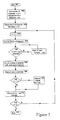
- the GSM CURSOR measurement procedure is carried out, in the DSP 43 (see Figure 10) at regular intervals of between 10 and 60 seconds during the handset's idle time and is described below with reference to Figure 7.
- Each procedure takes less than 1 second.
- Two repetitive characteristics of a BCCH transmission are readily identified. The first of these we call a marker signal and the second we call a code signal, which arrives at a known time after the marker.
- the marker signal could, for example, be a frequency-correction burst (FCB), and the code signal could be a synchronisation burst (SCH).
- FCB frequency-correction burst
- SCH synchronisation burst
- the handset waits for the arrival of a marker signal, and records the code signal (see Figure 7).
- the process begins at step 701 and the list of n channels and their frequencies are retrieved from the handset's neighbour list 702.
- a counter locked to the handset's reference oscillator is reset in step 703 and an index i is set to zero.
- the index is first incremented, at step 704 and the handset tunes, at step 705,to the first BCCH in the list, and waits for the arrival of the next marker signal in step 706.
- the clock tick count has reached the number corresponding to the arrival of the code signal, in step 708, the recording of about 2 x 140 bytes is then made in step 709, and the frame number is noted in step 711.
- the clock tick counter is then recorded in step 712 and, depending on the channel number being less than n (step 713), the process returns to step 704 and the handset then retunes to the next BCCH in the list, and awaits the arrival of the next marker signal on this channel.
- the value of the clock tick counter is recorded and, after the appropriate wait for the code signal, another 2 x 140 bytes are recorded. This process is repeated for all the channels in the list by cycling around the loop in the process until, in step 713, it is determined that the recordings have been made for all n channels.
- the recorded data is transferred to the CPU controller 46 for storing in RAM 48.
- the handset CPU controller, microprocessor 46 then performs some integer-based analysis of the data, storing the results in a cyclic buffer in RAM 48 in which the oldest values are replaced by the most recent ones.
- This analysis involves cross-correlating each of the recordings with a template based on the expected code signal (as mentioned above, the synchronisation burst SCH). The values around the peak of the cross-correlation are identified, and stored in RAM 48 in compressed form as described below.
- the values resident in the cyclic results buffer, which include the corresponding clock tick values are packed into one SMS package, which is then sent to the CPP where the handset's location is determined.
- the data that is to be sent to the CPP may consist of:
- the CBU operates in much the same way as the CRU.
- the main differences are that (a) the CBU monitors a much larger set of surrounding BCCH transmissions (typically 15-20), (b) the measurements are taken more frequently, say every 5 seconds, (c) the data is sent back to the CPP using any appropriate means e.g. an ISDN connection, (d) in some modes of operation, the CBU places a call to the CPP when it detects that a sufficiently-large time drift has occurred, and (e) the CBU can operate in network-monitoring and synchronisation modes as described above.
- the CPP typically functions in a CRU-activated mode.
- An incoming CURSOR SMS packet stimulates interrogation of the appropriate CBU or CBUs to extract the recorded data corresponding to the times of the CRU measurements.
- the CPP then uses standard procedures as described in our previous patent specifications mentioned above to calculate the position of the CRU using equations 7 above.
- the CPP may first consult an internal database of recent CBU measurements to determine if it has already obtained the required CBU information before requesting new data from any CBU.
- FIG. 8A The auto-correlation function of the extended training sequence in a GSM signal (illustrated in Figure 8A) is well known.
- the left hand side of this (corresponding to the negative time axis) is used as the left hand side of an estimated cross-correlation function (illustrated in Figure 8C) of the received signals and the expected extended training sequence.
- the right hand side of the auto-correlation function of the measured extended training sequence (illustrated in Figure 8B and corresponding to the positive time axis) is used as the right hand side of the estimated cross-correlation function (Figure 8C).
- the received signals are cross-correlated with the expected extended training sequence and the resulting measured cross-correlation function (illustrated in Figure 8D) compared with the estimated cross-correlation function ( Figure 8C) to find the timing offset.
Landscapes
- Engineering & Computer Science (AREA)
- Physics & Mathematics (AREA)
- General Physics & Mathematics (AREA)
- Radar, Positioning & Navigation (AREA)
- Remote Sensing (AREA)
- Signal Processing (AREA)
- Computer Networks & Wireless Communication (AREA)
- Mobile Radio Communication Systems (AREA)
- Position Fixing By Use Of Radio Waves (AREA)
- Stereophonic System (AREA)
- Control Of Position Or Direction (AREA)
- Telephonic Communication Services (AREA)
- Radio Relay Systems (AREA)
- Financial Or Insurance-Related Operations Such As Payment And Settlement (AREA)
- Exchange Systems With Centralized Control (AREA)
Applications Claiming Priority (5)
| Application Number | Priority Date | Filing Date | Title |
|---|---|---|---|
| GBGB9722324.2A GB9722324D0 (en) | 1997-10-22 | 1997-10-22 | Positioning system for digital telephone networks |
| GB9722324 | 1997-10-22 | ||
| GBGB9818450.0A GB9818450D0 (en) | 1998-08-24 | 1998-08-24 | Positioning system for digital telephone networks |
| GB9818450 | 1998-08-24 | ||
| EP98949119A EP1025453B1 (fr) | 1997-10-22 | 1998-10-21 | Systeme de positionnement pour reseaux telephoniques numeriques |
Related Parent Applications (1)
| Application Number | Title | Priority Date | Filing Date |
|---|---|---|---|
| EP98949119A Division EP1025453B1 (fr) | 1997-10-22 | 1998-10-21 | Systeme de positionnement pour reseaux telephoniques numeriques |
Publications (3)
| Publication Number | Publication Date |
|---|---|
| EP1271178A2 true EP1271178A2 (fr) | 2003-01-02 |
| EP1271178A3 EP1271178A3 (fr) | 2003-06-18 |
| EP1271178B1 EP1271178B1 (fr) | 2005-03-16 |
Family
ID=26312471
Family Applications (2)
| Application Number | Title | Priority Date | Filing Date |
|---|---|---|---|
| EP02100398A Expired - Lifetime EP1271178B1 (fr) | 1997-10-22 | 1998-10-21 | Système de positionnement pour réseaux téléphoniques numériques |
| EP98949119A Expired - Lifetime EP1025453B1 (fr) | 1997-10-22 | 1998-10-21 | Systeme de positionnement pour reseaux telephoniques numeriques |
Family Applications After (1)
| Application Number | Title | Priority Date | Filing Date |
|---|---|---|---|
| EP98949119A Expired - Lifetime EP1025453B1 (fr) | 1997-10-22 | 1998-10-21 | Systeme de positionnement pour reseaux telephoniques numeriques |
Country Status (23)
| Country | Link |
|---|---|
| EP (2) | EP1271178B1 (fr) |
| JP (1) | JP4294860B2 (fr) |
| KR (1) | KR100570315B1 (fr) |
| CN (1) | CN1317567C (fr) |
| AT (1) | ATE229653T1 (fr) |
| AU (1) | AU748322B2 (fr) |
| BG (1) | BG104363A (fr) |
| BR (1) | BR9814614A (fr) |
| CA (1) | CA2305586C (fr) |
| DE (2) | DE69829421T2 (fr) |
| DK (1) | DK1025453T3 (fr) |
| EA (1) | EA002006B1 (fr) |
| EE (1) | EE200000240A (fr) |
| ES (1) | ES2189253T3 (fr) |
| GE (1) | GEP20032874B (fr) |
| HK (1) | HK1030988A1 (fr) |
| HU (1) | HUP0004241A3 (fr) |
| MY (1) | MY122257A (fr) |
| PL (1) | PL340056A1 (fr) |
| TR (1) | TR200001096T2 (fr) |
| TW (1) | TW425797B (fr) |
| WO (1) | WO1999021028A1 (fr) |
| YU (1) | YU23300A (fr) |
Cited By (6)
| Publication number | Priority date | Publication date | Assignee | Title |
|---|---|---|---|---|
| US6894644B2 (en) | 2001-07-17 | 2005-05-17 | Cambridge Positioning Systems Limited | Radio positioning systems |
| US7260407B2 (en) | 2001-05-04 | 2007-08-21 | Cambridge Positioning Systems Ltd. | Radio location system measurement unit |
| US7508883B2 (en) | 2002-06-17 | 2009-03-24 | Cambridge Positioning Systems Limited | Radio positioning systems |
| US8255160B2 (en) | 2006-09-18 | 2012-08-28 | Cambridge Positioning Systems Limited | Integrated mobile terminal navigation |
| US8644850B2 (en) | 2009-10-05 | 2014-02-04 | Bae Systems Plc | Radio navigation |
| US20150198719A1 (en) * | 2014-01-14 | 2015-07-16 | Kinze Manufacturing, Inc. | Radio frequency position transducer |
Families Citing this family (25)
| Publication number | Priority date | Publication date | Assignee | Title |
|---|---|---|---|---|
| US6353412B1 (en) * | 1998-03-17 | 2002-03-05 | Qualcomm, Incorporated | Method and apparatus for determining position location using reduced number of GPS satellites and synchronized and unsynchronized base stations |
| GB9912724D0 (en) * | 1999-06-01 | 1999-08-04 | Cambridge Positioning Sys Ltd | Radio positioning system |
| KR20010080938A (ko) * | 1999-09-07 | 2001-08-25 | 요트.게.아. 롤페즈 | 최단 전달 시간에 기초한 이동 무선국의 위치를 계산하는방법 |
| US6285316B1 (en) | 2000-06-02 | 2001-09-04 | Cellguide Ltd. | Locating a mobile unit using signals from both mobile beacons and stationary beacons |
| US6985542B1 (en) | 2000-06-02 | 2006-01-10 | Cellguide Ltd. | Coherent processing of satellite signals to locate a mobile unit |
| US7183942B2 (en) | 2000-01-26 | 2007-02-27 | Origin Technologies Limited | Speed trap detection and warning system |
| US6346911B1 (en) * | 2000-03-30 | 2002-02-12 | Motorola, Inc. | Method and apparatus for determining time in a GPS receiver |
| AU2001238352A1 (en) * | 2000-04-03 | 2001-10-15 | Cellguide Ltd. | Distributed location system |
| WO2001078260A1 (fr) * | 2000-04-07 | 2001-10-18 | Cellguide Ltd. | Unite de reference pour un systeme de localisation d'un reseau cellulaire |
| US7228228B2 (en) | 2000-11-15 | 2007-06-05 | Sagentia Limited | Tag tracking |
| US7024331B2 (en) | 2000-11-15 | 2006-04-04 | Scientific Generics Limited | Tag tracking |
| EP1235076A1 (fr) * | 2001-02-23 | 2002-08-28 | Cambridge Positioning Systems Limited | Perfectionnements aux procédés et dispositifs de positionnement |
| US6950663B2 (en) | 2001-08-24 | 2005-09-27 | Nokia Mobile Phones Ltd. | Method of locating a mobile station based on observed time difference |
| EP1301054A1 (fr) * | 2001-10-04 | 2003-04-09 | Cambridge Positioning Systems Limited | Concernant la coordination d'une référence de temps dans un terminal cellulaire ou une station de base |
| EP1316812A1 (fr) * | 2001-11-28 | 2003-06-04 | Sony International (Europe) GmbH | Système de positionnement de dispositif mobile dans un réseau mobile cellulaire |
| EP1365613B1 (fr) | 2002-05-22 | 2006-06-21 | Cambridge Positioning Systems Limited | Système de localisation et procédé |
| EP1394562B1 (fr) | 2002-08-28 | 2011-01-19 | Cambridge Positioning Systems Limited | Perfectionnements aux systèmes de radio-localisation |
| JP4287476B2 (ja) | 2004-01-26 | 2009-07-01 | ケンブリッジ ポジショニング システムズ リミテッド | 移動端末における較正時間情報の転送 |
| FR2878684B1 (fr) * | 2004-11-30 | 2007-04-20 | Cit Alcatel | Dispositif de localisation de terminal mobile au moyen de signaux a marquage temporel corrige provenant de stations de base d'un reseau mobile asynchrone |
| KR100694512B1 (ko) * | 2004-12-24 | 2007-03-13 | 한국철도기술연구원 | 지상무선국에서의 열차 위치결정오차 보정방법 |
| US9274207B2 (en) | 2006-02-01 | 2016-03-01 | Zih Corp. | System and method for determining signal source location in wireless local area network |
| US8184046B2 (en) * | 2008-09-17 | 2012-05-22 | St-Ericsson Sa | Time reference system |
| CN107113762B (zh) * | 2015-05-06 | 2020-02-21 | 华为技术有限公司 | 一种定位方法、定位服务器及定位系统 |
| EP3465250A1 (fr) * | 2016-05-25 | 2019-04-10 | Fraunhofer Gesellschaft zur Förderung der angewandten Forschung E.V. | Conception de forme d'onde pour localiser un système |
| US11061104B2 (en) * | 2019-05-24 | 2021-07-13 | U-Blox Ag | Method and apparatus for positioning with wireless signals |
Citations (6)
| Publication number | Priority date | Publication date | Assignee | Title |
|---|---|---|---|---|
| EP0303371B1 (fr) * | 1987-08-10 | 1993-03-10 | Lynxvale Limited | Système de navigation et de poursuite |
| US5293645A (en) * | 1991-10-04 | 1994-03-08 | Sharp Microelectronics Technology, Inc. | Apparatus and method for locating mobile and portable radio terminals in a radio network |
| DE19621225A1 (de) * | 1995-05-31 | 1996-12-05 | Gen Electric | Leistungsreduziertes GPS-gestütztes System zum Verfolgen mehrerer Objekte von einem zentralen Ort |
| WO1997011384A1 (fr) * | 1995-09-19 | 1997-03-27 | Cambridge Positioning Systems Limited | Systeme de localisation |
| WO1997023785A1 (fr) * | 1995-12-22 | 1997-07-03 | University Of Technology, Sydney | Systeme de localisation et de poursuite |
| WO1997030360A2 (fr) * | 1996-02-16 | 1997-08-21 | Telefonaktiebolaget Lm Ericsson (Publ) | Methode et dispositif concernant des systemes de telecommunications |
-
1998
- 1998-10-21 PL PL98340056A patent/PL340056A1/xx unknown
- 1998-10-21 HU HU0004241A patent/HUP0004241A3/hu unknown
- 1998-10-21 EE EEP200000240A patent/EE200000240A/xx unknown
- 1998-10-21 JP JP2000517292A patent/JP4294860B2/ja not_active Expired - Fee Related
- 1998-10-21 GE GEAP19985360A patent/GEP20032874B/en unknown
- 1998-10-21 DE DE69829421T patent/DE69829421T2/de not_active Expired - Lifetime
- 1998-10-21 AU AU95498/98A patent/AU748322B2/en not_active Ceased
- 1998-10-21 AT AT98949119T patent/ATE229653T1/de not_active IP Right Cessation
- 1998-10-21 EA EA200000446A patent/EA002006B1/ru not_active IP Right Cessation
- 1998-10-21 TR TR2000/01096T patent/TR200001096T2/xx unknown
- 1998-10-21 CA CA002305586A patent/CA2305586C/fr not_active Expired - Fee Related
- 1998-10-21 DE DE69810149T patent/DE69810149T2/de not_active Expired - Lifetime
- 1998-10-21 KR KR1020007004322A patent/KR100570315B1/ko not_active IP Right Cessation
- 1998-10-21 ES ES98949119T patent/ES2189253T3/es not_active Expired - Lifetime
- 1998-10-21 WO PCT/GB1998/003149 patent/WO1999021028A1/fr not_active Application Discontinuation
- 1998-10-21 EP EP02100398A patent/EP1271178B1/fr not_active Expired - Lifetime
- 1998-10-21 YU YU23300A patent/YU23300A/sh unknown
- 1998-10-21 CN CNB988104709A patent/CN1317567C/zh not_active Expired - Lifetime
- 1998-10-21 BR BR9814614-9A patent/BR9814614A/pt not_active IP Right Cessation
- 1998-10-21 DK DK98949119T patent/DK1025453T3/da active
- 1998-10-21 EP EP98949119A patent/EP1025453B1/fr not_active Expired - Lifetime
- 1998-10-22 MY MYPI98004825A patent/MY122257A/en unknown
- 1998-12-10 TW TW087120538A patent/TW425797B/zh not_active IP Right Cessation
-
2000
- 2000-04-21 BG BG104363A patent/BG104363A/bg unknown
-
2001
- 2001-01-09 HK HK01100214A patent/HK1030988A1/xx not_active IP Right Cessation
Patent Citations (6)
| Publication number | Priority date | Publication date | Assignee | Title |
|---|---|---|---|---|
| EP0303371B1 (fr) * | 1987-08-10 | 1993-03-10 | Lynxvale Limited | Système de navigation et de poursuite |
| US5293645A (en) * | 1991-10-04 | 1994-03-08 | Sharp Microelectronics Technology, Inc. | Apparatus and method for locating mobile and portable radio terminals in a radio network |
| DE19621225A1 (de) * | 1995-05-31 | 1996-12-05 | Gen Electric | Leistungsreduziertes GPS-gestütztes System zum Verfolgen mehrerer Objekte von einem zentralen Ort |
| WO1997011384A1 (fr) * | 1995-09-19 | 1997-03-27 | Cambridge Positioning Systems Limited | Systeme de localisation |
| WO1997023785A1 (fr) * | 1995-12-22 | 1997-07-03 | University Of Technology, Sydney | Systeme de localisation et de poursuite |
| WO1997030360A2 (fr) * | 1996-02-16 | 1997-08-21 | Telefonaktiebolaget Lm Ericsson (Publ) | Methode et dispositif concernant des systemes de telecommunications |
Cited By (8)
| Publication number | Priority date | Publication date | Assignee | Title |
|---|---|---|---|---|
| US7260407B2 (en) | 2001-05-04 | 2007-08-21 | Cambridge Positioning Systems Ltd. | Radio location system measurement unit |
| US6894644B2 (en) | 2001-07-17 | 2005-05-17 | Cambridge Positioning Systems Limited | Radio positioning systems |
| US7508883B2 (en) | 2002-06-17 | 2009-03-24 | Cambridge Positioning Systems Limited | Radio positioning systems |
| US8255160B2 (en) | 2006-09-18 | 2012-08-28 | Cambridge Positioning Systems Limited | Integrated mobile terminal navigation |
| US8644850B2 (en) | 2009-10-05 | 2014-02-04 | Bae Systems Plc | Radio navigation |
| US8963775B2 (en) | 2009-10-05 | 2015-02-24 | Bae Systems Plc | Tracking radio signal sources |
| US9261579B2 (en) | 2009-10-05 | 2016-02-16 | Bae Systems Plc | Radio positioning of a mobile receiver using a virtual positioning reference |
| US20150198719A1 (en) * | 2014-01-14 | 2015-07-16 | Kinze Manufacturing, Inc. | Radio frequency position transducer |
Also Published As
Similar Documents
| Publication | Publication Date | Title |
|---|---|---|
| EP1025453B1 (fr) | Systeme de positionnement pour reseaux telephoniques numeriques | |
| US7593736B1 (en) | Positioning system for digital telephone networks | |
| JP3418612B2 (ja) | セルラまたはpcsネットワークを介してgps受信機を補助する方法およびシステム | |
| JP3383797B2 (ja) | 移動送信機の位置を判定する方法およびシステム | |
| US7359719B1 (en) | Radio positioning systems | |
| US6925292B2 (en) | Method, apparatus and system for synchronizing a cellular communication system to GPS time | |
| EP2206272B1 (fr) | Système et procédé de distribution de temps et de fréquence sur un réseau | |
| US8335173B2 (en) | Inserting time of departure information in frames to support multi-channel location techniques | |
| US7454217B2 (en) | Method and apparatus for wireless network timekeeping and synchronization | |
| KR100771410B1 (ko) | 셀룰러 및 피씨에스 네트워크에서의 기지국들을동기시키는 시스템 및 방법 | |
| EP1005773A1 (fr) | Systeme de localisation en telephonie mobile numerique | |
| EP1376150A1 (fr) | Système de radiolocalisation avec suppression d'interférence | |
| IL135613A (en) | A scaled-down search space for moving a global location system receiver code for a cell phone system | |
| US9341701B2 (en) | Method for synchronizing time measurements carried out in a radio communication network for geolocation purposes | |
| WO2002025308A1 (fr) | Terminal radio mobile et procede et systeme associes | |
| JPH10322752A (ja) | セルラ移動通信における移動局位置推定方法および基地局装置と移動局装置 | |
| US20040087277A1 (en) | Method and apparatus for improving accuracy of radio timing measurements | |
| US20040087269A1 (en) | Methods and apparatus for improving accuracy of radio timing measurements | |
| KR20010062101A (ko) | 시간 교정 방법 | |
| EP1301054A1 (fr) | Concernant la coordination d'une référence de temps dans un terminal cellulaire ou une station de base | |
| JP3894056B2 (ja) | セルラ基地局の送信タイミングのオフセット測定方法および測定システム | |
| MXPA00003929A (es) | Disposicion de posicionamiento para redes telefonicas digitales | |
| CZ20001475A3 (cs) | Zařízení ke zjišťování polohy digitální telefonní sítě | |
| WO2000010266A1 (fr) | Systeme et procede d'evaluation des decalages de tranches de temps dans un reseau amrt asynchrone | |
| WO2022226233A1 (fr) | Procédés de synchronisation et de localisation dans le temps dans un réseau maillé |
Legal Events
| Date | Code | Title | Description |
|---|---|---|---|
| PUAI | Public reference made under article 153(3) epc to a published international application that has entered the european phase |
Free format text: ORIGINAL CODE: 0009012 |
|
| AC | Divisional application: reference to earlier application |
Ref document number: 1025453 Country of ref document: EP |
|
| AK | Designated contracting states |
Kind code of ref document: A2 Designated state(s): AT BE CH CY DE DK ES FI FR GB GR IE IT LI LU MC NL PT SE |
|
| AX | Request for extension of the european patent |
Free format text: AL;LT;LV;MK;RO;SI |
|
| PUAL | Search report despatched |
Free format text: ORIGINAL CODE: 0009013 |
|
| AK | Designated contracting states |
Designated state(s): AT BE CH CY DE DK ES FI FR GB GR IE IT LI LU MC NL PT SE |
|
| AX | Request for extension of the european patent |
Extension state: AL LT LV MK RO SI |
|
| RIC1 | Information provided on ipc code assigned before grant |
Ipc: 7G 01S 5/14 A Ipc: 7G 01S 5/10 B |
|
| 17P | Request for examination filed |
Effective date: 20031209 |
|
| AKX | Designation fees paid |
Designated state(s): DE FR GB |
|
| 17Q | First examination report despatched |
Effective date: 20040329 |
|
| GRAP | Despatch of communication of intention to grant a patent |
Free format text: ORIGINAL CODE: EPIDOSNIGR1 |
|
| GRAS | Grant fee paid |
Free format text: ORIGINAL CODE: EPIDOSNIGR3 |
|
| GRAA | (expected) grant |
Free format text: ORIGINAL CODE: 0009210 |
|
| RIN1 | Information on inventor provided before grant (corrected) |
Inventor name: DUFFETT-SMITH, PETER JAMES Inventor name: HANSEN, PAUL |
|
| AC | Divisional application: reference to earlier application |
Ref document number: 1025453 Country of ref document: EP Kind code of ref document: P |
|
| AK | Designated contracting states |
Kind code of ref document: B1 Designated state(s): DE FR GB |
|
| REG | Reference to a national code |
Ref country code: GB Ref legal event code: FG4D |
|
| REF | Corresponds to: |
Ref document number: 69829421 Country of ref document: DE Date of ref document: 20050421 Kind code of ref document: P |
|
| PLBE | No opposition filed within time limit |
Free format text: ORIGINAL CODE: 0009261 |
|
| STAA | Information on the status of an ep patent application or granted ep patent |
Free format text: STATUS: NO OPPOSITION FILED WITHIN TIME LIMIT |
|
| ET | Fr: translation filed | ||
| 26N | No opposition filed |
Effective date: 20051219 |
|
| REG | Reference to a national code |
Ref country code: FR Ref legal event code: PLFP Year of fee payment: 18 |
|
| PGFP | Annual fee paid to national office [announced via postgrant information from national office to epo] |
Ref country code: FR Payment date: 20150924 Year of fee payment: 18 |
|
| PGFP | Annual fee paid to national office [announced via postgrant information from national office to epo] |
Ref country code: DE Payment date: 20150930 Year of fee payment: 18 |
|
| REG | Reference to a national code |
Ref country code: DE Ref legal event code: R119 Ref document number: 69829421 Country of ref document: DE |
|
| REG | Reference to a national code |
Ref country code: FR Ref legal event code: ST Effective date: 20170630 |
|
| PG25 | Lapsed in a contracting state [announced via postgrant information from national office to epo] |
Ref country code: FR Free format text: LAPSE BECAUSE OF NON-PAYMENT OF DUE FEES Effective date: 20161102 Ref country code: DE Free format text: LAPSE BECAUSE OF NON-PAYMENT OF DUE FEES Effective date: 20170503 |
|
| PGFP | Annual fee paid to national office [announced via postgrant information from national office to epo] |
Ref country code: GB Payment date: 20170925 Year of fee payment: 20 |
|
| REG | Reference to a national code |
Ref country code: GB Ref legal event code: PE20 Expiry date: 20181020 |
|
| PG25 | Lapsed in a contracting state [announced via postgrant information from national office to epo] |
Ref country code: GB Free format text: LAPSE BECAUSE OF EXPIRATION OF PROTECTION Effective date: 20181020 |