EP1270283B1 - Suspension module - Google Patents
Suspension module Download PDFInfo
- Publication number
- EP1270283B1 EP1270283B1 EP02254598A EP02254598A EP1270283B1 EP 1270283 B1 EP1270283 B1 EP 1270283B1 EP 02254598 A EP02254598 A EP 02254598A EP 02254598 A EP02254598 A EP 02254598A EP 1270283 B1 EP1270283 B1 EP 1270283B1
- Authority
- EP
- European Patent Office
- Prior art keywords
- subframe
- suspension
- rails
- pair
- suspension system
- Prior art date
- Legal status (The legal status is an assumption and is not a legal conclusion. Google has not performed a legal analysis and makes no representation as to the accuracy of the status listed.)
- Expired - Lifetime
Links
Images

Classifications
-
- B—PERFORMING OPERATIONS; TRANSPORTING
- B60—VEHICLES IN GENERAL
- B60G—VEHICLE SUSPENSION ARRANGEMENTS
- B60G99/00—Subject matter not provided for in other groups of this subclass
-
- B—PERFORMING OPERATIONS; TRANSPORTING
- B60—VEHICLES IN GENERAL
- B60G—VEHICLE SUSPENSION ARRANGEMENTS
- B60G11/00—Resilient suspensions characterised by arrangement, location or kind of springs
- B60G11/26—Resilient suspensions characterised by arrangement, location or kind of springs having fluid springs only, e.g. hydropneumatic springs
- B60G11/27—Resilient suspensions characterised by arrangement, location or kind of springs having fluid springs only, e.g. hydropneumatic springs wherein the fluid is a gas
-
- B—PERFORMING OPERATIONS; TRANSPORTING
- B60—VEHICLES IN GENERAL
- B60G—VEHICLE SUSPENSION ARRANGEMENTS
- B60G9/00—Resilient suspensions of a rigid axle or axle housing for two or more wheels
- B60G9/02—Resilient suspensions of a rigid axle or axle housing for two or more wheels the axle or housing being pivotally mounted on the vehicle, e.g. the pivotal axis being parallel to the longitudinal axis of the vehicle
-
- B—PERFORMING OPERATIONS; TRANSPORTING
- B62—LAND VEHICLES FOR TRAVELLING OTHERWISE THAN ON RAILS
- B62D—MOTOR VEHICLES; TRAILERS
- B62D21/00—Understructures, i.e. chassis frame on which a vehicle body may be mounted
- B62D21/11—Understructures, i.e. chassis frame on which a vehicle body may be mounted with resilient means for suspension, e.g. of wheels or engine; sub-frames for mounting engine or suspensions
-
- B—PERFORMING OPERATIONS; TRANSPORTING
- B60—VEHICLES IN GENERAL
- B60G—VEHICLE SUSPENSION ARRANGEMENTS
- B60G2200/00—Indexing codes relating to suspension types
- B60G2200/10—Independent suspensions
- B60G2200/13—Independent suspensions with longitudinal arms only
- B60G2200/132—Independent suspensions with longitudinal arms only with a single trailing arm
-
- B—PERFORMING OPERATIONS; TRANSPORTING
- B60—VEHICLES IN GENERAL
- B60G—VEHICLE SUSPENSION ARRANGEMENTS
- B60G2204/00—Indexing codes related to suspensions per se or to auxiliary parts
- B60G2204/10—Mounting of suspension elements
- B60G2204/14—Mounting of suspension arms
- B60G2204/143—Mounting of suspension arms on the vehicle body or chassis
-
- B—PERFORMING OPERATIONS; TRANSPORTING
- B60—VEHICLES IN GENERAL
- B60G—VEHICLE SUSPENSION ARRANGEMENTS
- B60G2204/00—Indexing codes related to suspensions per se or to auxiliary parts
- B60G2204/10—Mounting of suspension elements
- B60G2204/15—Mounting of subframes
Definitions
- the present invention relates generally to a suspension module in particular for use with an independent suspension preferably including a pair of pivotal semi-trailing arms each having an airbag support which supports an airbag positioned between the semi-trailing arms and a subframe.
- a suspension system commonly includes a pair of parallel suspension arms which are pivotally attached to generally parallel frame rails of the vehicle chassis.
- An airbag is attached to the frame rail to compensate for various wheel load conditions.
- the suspension system translates road forces imparted to the wheels into rotational movement of the suspension arms relative to the frame rail. The rotational movement of the suspension arm is cushioned by the airbags.
- the airbags are mounted to a transverse beam extending across the ends of the suspension arms and supported on the frame rails.
- This prior art system is not an independent suspension.
- the airbags are mounted to the suspension arms over the axle centerline and directly attached to the frame rails of the vehicle chassis. This positioning of the airbags over the axle centerline in an independent suspension makes the fitting of the suspension system under the frame rail of the vehicle chassis difficult. This problem increases when double tires are employed and as vehicle weight increases, requiring larger airbags.
- US Patent US5088763 discloses a system whereby an air spring is used in conjunction with a slider suspension.
- GB896181 discloses a trailing arm suspension system used in conjunction with an air bag.
- a suspension module for use in an independent suspension system is secured to the frame of a vehicle chassis and includes a subframe having a pair of spaced apart generally parallel subframe rails and a bridge supported therebetween.
- the suspension module further includes a pair of independently moveable suspension semi-trailing arms which are pivotally attached to the subframe rails.
- a spindle is bolted on each of the semi-trailing arms to receive a wheel.
- Each of the semi-trailing arms further include an airbag support onto which an airbag is mounted.
- the airbags provide vertical load support and are positioned between the airbag supports and the subframe rails.
- a shock absorber extending from each the semi-trailing arms to the subframe rails dampens movement.
- the shock absorbers are positioned directly over the axle centerline.
- a drive line transmits rotational drive from a transmission to a carrier housing attached to the bridge of the subframe by a carrier by visco-elastic mounts.
- the carrier housing can be detached from the bridge, allowing the carrier housing to be rotated 180° between a rear engine configuration and a front engine configuration.
- a carden shaft extending from the carrier housing to each of the spindles transmits rotational drive from the carrier housing to the spindles.
- FIG. 1 illustrates a perspective view of the suspension module 20 of the present invention.
- the suspension module 20 is employed in an independent suspension system of a heavy vehicle, such as a commercial truck, to improve design and flexibility.
- the suspension module 20 includes a subframe 22 having a pair of spaced apart generally parallel subframe rails 24 each including a first end 26 having a bracket 44 and an opposing second end 28.
- a bridge 30 extends between the subframe rails 24.
- the subframe 22 defines a longitudinal axis 36 which extends along the longitudinal length of the vehicle.
- the subframe rails 24 are secured to the frame 32 of a vehicle chassis by an attachment mechanism 34, such as bolts, welding, or the like.
- the vehicle fame 32 provides the primary structural support of the body of the vehicle.
- the suspension module 20 further includes a pair of independently moveable semi-trailing arms 38.
- a first end 40 of the semi-trailing arms 38 is pivotally attached to the hanger brackets 44 of the subframe rails 24.
- the semi-trailing arms 38 are independently pivotal relative to the subframe rails 24 about pivot axis 80.
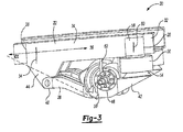
- An angle ⁇ (as shown in Figure 3 ) is defined between the longitudinal axis 36 of the vehicle frame 32 and the semi-trailing arms 38. The angle ⁇ is preferably greater than 65°.
- a hub assembly 48 extends from each of the semi-trailing arms 38.
- the hub assemblies 48 each include a spindle 50 bolted on a knuckle which provides an axle centerline 52.
- Each spindle 50 receives a wheel (not shown).
- a second end 42 of each of the semi-trailing arms 38 includes an airbag support 54 onto which an airbag 56 is mounted.
- the airbags 56 are located on the side of the axle centerline 52 opposite to the first end 40 of the semi-trailing arms 38 and are positioned between the airbag supports 54 and the second end 28 of the subframe rails 24.
- the airbags 56 are attached to the subframe rails 24 by airbag brackets 58 which are attached to the subframe rails 24 by fasteners 60 such as bolts, welding, or the like.
- the airbags 56 provide vertical load support to the independent suspension system and damped the force during movement of the semi-trailing arms 38.
- the airbags 56 are preferably adjustable based on vehicle load conditions in a known manner. Although airbags 56 have been disclosed, it is to be understood that the air springs or other vertical load supporters can also be employed.
- a shock absorber 62 is positioned between the semi-trailing arms 38 and the subframe rail 24 to dampen movement of the semi-trailing arms 38.
- the shock absorbers 62 are positioned directly over the axle centerline 52.
- the shock absorbers 62 can be located anywhere on the semi-trailing arms 38.
- a carrier housing 66 is attached to the bridge 30 of the subframe 22.
- the carrier housing 66 includes brackets 68 which are attached to the bridge 30 by visco-elastic mounts 74, providing for vibrational damping.
- the carrier housing 66 can be rotated 180° to change between a rear engine configuration and a front engine configuration by detaching the brackets 68 of the carrier housing 66 from the bridge 30.
- the carrier housing 66 can be rigidly mounted to the bridge 30, and the bridge 30 is mounted to the subframe 22 by the visco-elastic mounts 74.
- a drive line 70 brings rotational drive from a transmission 72, shown schematically, to the carrier housing 66.
- a carden shaft 76 extending from the opposing sides of the carrier housing 66 to each of the spindles 50 transmits rotational drive from the carrier housing 66 to the spindles 50.
- the suspension module 20 of the present invention having airbags 56 positioned between the airbags supports 54 and the subframe rails 24 can be quickly and easily secured to the frame 32 of a vehicle chassis. As the airbags 56 are positioned behind the axle centerline 52, the suspension module 20 can be easily installed in the vehicle.
- the independently semi-trailing arms 38 of the suspension module 20 allows for a change in camber with wheel vertical travel, and a toe change that is favorable to vehicle stability.
Landscapes
- Engineering & Computer Science (AREA)
- Mechanical Engineering (AREA)
- Chemical & Material Sciences (AREA)
- Combustion & Propulsion (AREA)
- Transportation (AREA)
- Vehicle Body Suspensions (AREA)
- Bridges Or Land Bridges (AREA)
- Body Structure For Vehicles (AREA)
Description
- The present invention relates generally to a suspension module in particular for use with an independent suspension preferably including a pair of pivotal semi-trailing arms each having an airbag support which supports an airbag positioned between the semi-trailing arms and a subframe.
- Heavy vehicles, such as trucks, typically utilize a suspension system to provide a smooth and comfortable ride. A suspension system commonly includes a pair of parallel suspension arms which are pivotally attached to generally parallel frame rails of the vehicle chassis. An airbag is attached to the frame rail to compensate for various wheel load conditions. The suspension system translates road forces imparted to the wheels into rotational movement of the suspension arms relative to the frame rail. The rotational movement of the suspension arm is cushioned by the airbags.
- In one prior art commercial vehicle system, the airbags are mounted to a transverse beam extending across the ends of the suspension arms and supported on the frame rails. This prior art system is not an independent suspension.
- In another prior art independent suspension system, the airbags are mounted to the suspension arms over the axle centerline and directly attached to the frame rails of the vehicle chassis. This positioning of the airbags over the axle centerline in an independent suspension makes the fitting of the suspension system under the frame rail of the vehicle chassis difficult. This problem increases when double tires are employed and as vehicle weight increases, requiring larger airbags.
- Finally, coil spring positioned over the axle centerline and attached directly to the frame have been employed in passenger vehicles.
US Patent US5088763 discloses a system whereby an air spring is used in conjunction with a slider suspension.GB896181 - A suspension module for use in an independent suspension system is secured to the frame of a vehicle chassis and includes a subframe having a pair of spaced apart generally parallel subframe rails and a bridge supported therebetween. The suspension module further includes a pair of independently moveable suspension semi-trailing arms which are pivotally attached to the subframe rails. A spindle is bolted on each of the semi-trailing arms to receive a wheel.
- Each of the semi-trailing arms further include an airbag support onto which an airbag is mounted. The airbags provide vertical load support and are positioned between the airbag supports and the subframe rails. A shock absorber extending from each the semi-trailing arms to the subframe rails dampens movement. Preferably, the shock absorbers are positioned directly over the axle centerline.
- A drive line transmits rotational drive from a transmission to a carrier housing attached to the bridge of the subframe by a carrier by visco-elastic mounts. The carrier housing can be detached from the bridge, allowing the carrier housing to be rotated 180° between a rear engine configuration and a front engine configuration. A carden shaft extending from the carrier housing to each of the spindles transmits rotational drive from the carrier housing to the spindles.
- These and other features of the present invention will be best understood from the following specification and drawings.
- The various features and advantages of the invention will become apparent to those skilled in the art from the following detailed description of the currently preferred embodiment. The drawings that accompany the detailed description can be briefly described as follows:
-
Figure 1 illustrates a perspective view of the suspension module of the present invention including semi-trailing arms with airbag supports; -
Figure 2 illustrates a bottom view of the suspension module; and -
Figure 3 illustrates a side view of the suspension module. -
Figure 1 illustrates a perspective view of thesuspension module 20 of the present invention. Thesuspension module 20 is employed in an independent suspension system of a heavy vehicle, such as a commercial truck, to improve design and flexibility. Thesuspension module 20 includes asubframe 22 having a pair of spaced apart generallyparallel subframe rails 24 each including afirst end 26 having abracket 44 and an opposingsecond end 28. Abridge 30 extends between thesubframe rails 24. Thesubframe 22 defines alongitudinal axis 36 which extends along the longitudinal length of the vehicle. - The
subframe rails 24 are secured to theframe 32 of a vehicle chassis by anattachment mechanism 34, such as bolts, welding, or the like. Thevehicle fame 32 provides the primary structural support of the body of the vehicle. - As illustrated in
Figure 2 , thesuspension module 20 further includes a pair of independently moveablesemi-trailing arms 38. Afirst end 40 of thesemi-trailing arms 38 is pivotally attached to thehanger brackets 44 of thesubframe rails 24. Thesemi-trailing arms 38 are independently pivotal relative to thesubframe rails 24 aboutpivot axis 80. An angle α (as shown inFigure 3 ) is defined between thelongitudinal axis 36 of thevehicle frame 32 and thesemi-trailing arms 38. The angle α is preferably greater than 65°. - A
hub assembly 48 extends from each of thesemi-trailing arms 38. Thehub assemblies 48 each include aspindle 50 bolted on a knuckle which provides anaxle centerline 52. Eachspindle 50 receives a wheel (not shown). - A
second end 42 of each of thesemi-trailing arms 38 includes anairbag support 54 onto which anairbag 56 is mounted. Preferably, theairbags 56 are located on the side of theaxle centerline 52 opposite to thefirst end 40 of thesemi-trailing arms 38 and are positioned between the airbag supports 54 and thesecond end 28 of thesubframe rails 24. Theairbags 56 are attached to thesubframe rails 24 byairbag brackets 58 which are attached to thesubframe rails 24 byfasteners 60 such as bolts, welding, or the like. - The
airbags 56 provide vertical load support to the independent suspension system and damped the force during movement of thesemi-trailing arms 38. Theairbags 56 are preferably adjustable based on vehicle load conditions in a known manner. Althoughairbags 56 have been disclosed, it is to be understood that the air springs or other vertical load supporters can also be employed. - A
shock absorber 62 is positioned between thesemi-trailing arms 38 and thesubframe rail 24 to dampen movement of thesemi-trailing arms 38. Preferably, theshock absorbers 62 are positioned directly over theaxle centerline 52. However, it is to be understood that theshock absorbers 62 can be located anywhere on thesemi-trailing arms 38. - As shown in
Figure 2 , acarrier housing 66 is attached to thebridge 30 of thesubframe 22. Thecarrier housing 66 includesbrackets 68 which are attached to thebridge 30 by visco-elastic mounts 74, providing for vibrational damping. Thecarrier housing 66 can be rotated 180° to change between a rear engine configuration and a front engine configuration by detaching thebrackets 68 of thecarrier housing 66 from thebridge 30. Alternatively, thecarrier housing 66 can be rigidly mounted to thebridge 30, and thebridge 30 is mounted to thesubframe 22 by the visco-elastic mounts 74. - A drive line 70 brings rotational drive from a
transmission 72, shown schematically, to thecarrier housing 66. A carden shaft 76 extending from the opposing sides of thecarrier housing 66 to each of thespindles 50 transmits rotational drive from thecarrier housing 66 to thespindles 50. - The
suspension module 20 of the presentinvention having airbags 56 positioned between the airbags supports 54 and thesubframe rails 24 can be quickly and easily secured to theframe 32 of a vehicle chassis. As theairbags 56 are positioned behind theaxle centerline 52, thesuspension module 20 can be easily installed in the vehicle. The independentlysemi-trailing arms 38 of thesuspension module 20 allows for a change in camber with wheel vertical travel, and a toe change that is favorable to vehicle stability. - The foregoing description is only exemplary of the principles of the invention. Many modifications and variations of the present invention are possible in light of the above teachings. The preferred embodiments of this invention have been disclosed, however, so that one of ordinary skill in the art would recognize that certain modifications would come within the scope of this invention. It is, therefore, to be understood that within the scope of the appended claims, the invention may be practiced otherwise than as specifically described. For that reason the following claims should be studied to determine the true scope and content of this invention.
Claims (13)
- A suspension system comprising:a suspension module (20) comprising:a subframe (22) including a pair of generally parallel subframe rails (24);a pair of suspension arms (38) pivotally attached to said subframe rails, and each independently pivotal at a first end about a pivot axis; anda load support (56) such as an airbag, an airspring or the like, mounted on an opposing second end of each of said pair of suspension arms and attached to said subframe rails,
characterised in that;the suspension system further comprises a vehicle frame (32) comprising a pair of generally parallel frame rails, andthe subframe (22) is secured to said vehicle frame (32)with the pair of generally parallel subframe rails extending substantially parallel to the pair of generally parallel frame rails. - A suspension system as recited in claim 1 wherein a shock absorber (62) is positioned between each of said suspension arms and said subframe rails.
- A suspension system as recited in claim 1 or 2 further including a lateral support (30) extending between said pair of subframe rails.
- A suspension system comprising:a subframe (22) including a pair of generally parallel subframe rails (24) attached to a vehicle frame and a lateral support (30) extending between said subframe rails;a pair of suspension arms (38) pivotally attached to said subframe rails, and each independently pivotal at a first end about a pivot axis;a load support (56), such as an airbag, airspring or the like, mounted on an opposing second end of each of said pair of suspension arms and attached to said subframe rails;a spindle (50) bolted on each of said suspension arm; anda shock absorber (62) positioned between each of said suspension arms and said subframe rail,
characterised in that; the suspension system further comprises a vehicle frame (32) comprising a pair of generally parallel frame rails, and the subframe (22) is secured to said vehicle frame (32) with the pair of generally parallel subframe rails extending substantially parallel to the pair of generally parallel frame rails. - A suspension system as recited in any preceding claim wherein said load supports (56) are attached to said subframe rails by load support brackets (58).
- A suspension system as recited in any preceding claim wherein each of said suspension arms are semi-trailing arms, and a spindle (50) is bolted on each of said suspension arms between said first end and said second end.
- A suspension system as recited in any preceding claim wherein said load supports (58) are located on a side of said spindle opposite to said pivot axis.
- A suspension system as recited in any preceding claim wherein said shocks absorbers (62) are positioned approximately over said axle centerline or approximately over said spindle.
- A suspension system as recited in any preceding claim further including a drive line (70) which transfers rotational drive from a transmission to a carrier housing secured to said lateral support, and a carden shaft (76) that transfers rotational drive from said carrier housing to a spindle bolted on each of said suspension arms.
- A suspension system as recited in any preceding claim wherein said carrier housing is secured to said lateral support by visco-elastic mounts (74).
- A suspension system as defined in any preceding claim wherein the load support is an airbag (58) or an airspring.
- A suspension system as defined in any preceding claim wherein the suspension arms are semi-trailing arms.
- A suspension system as defined in any preceding claim wherein a longitudinal axis of the subframe extends generally parallel to the vehicle frame.
Applications Claiming Priority (2)
| Application Number | Priority Date | Filing Date | Title |
|---|---|---|---|
| US30202101P | 2001-06-29 | 2001-06-29 | |
| US302021P | 2001-06-29 |
Publications (3)
| Publication Number | Publication Date |
|---|---|
| EP1270283A2 EP1270283A2 (en) | 2003-01-02 |
| EP1270283A3 EP1270283A3 (en) | 2004-02-11 |
| EP1270283B1 true EP1270283B1 (en) | 2011-05-11 |
Family
ID=23165919
Family Applications (1)
| Application Number | Title | Priority Date | Filing Date |
|---|---|---|---|
| EP02254598A Expired - Lifetime EP1270283B1 (en) | 2001-06-29 | 2002-06-28 | Suspension module |
Country Status (3)
| Country | Link |
|---|---|
| US (1) | US6929084B2 (en) |
| EP (1) | EP1270283B1 (en) |
| ES (1) | ES2366605T3 (en) |
Families Citing this family (14)
| Publication number | Priority date | Publication date | Assignee | Title |
|---|---|---|---|---|
| US6398251B1 (en) * | 1997-01-31 | 2002-06-04 | Dallas Smith Corporation | Axleless vehicle suspension system |
| US6637809B1 (en) * | 2002-12-12 | 2003-10-28 | International Truck Intellectual Property Company, Llc. | Vehicle with novel frame rails |
| AU2011218652B2 (en) * | 2003-04-08 | 2013-05-02 | AL-KO Chassis Systems Pty Ltd | Integrated suspension and chassis assembly |
| AU2003901599A0 (en) * | 2003-04-08 | 2003-05-01 | AL-KO Chassis Systems Pty Ltd | Integrated suspension and chassis assembly |
| WO2005039900A2 (en) * | 2003-10-24 | 2005-05-06 | Aloha, Llc | Suspensions for low floor vehicles |
| DE102006044107A1 (en) * | 2006-09-20 | 2008-03-27 | Man Nutzfahrzeuge Ag | Subframe with independent suspension |
| DE102008045924A1 (en) * | 2008-09-04 | 2010-03-18 | Daimler Ag | Supporting structure for use as rear structure of frame of e.g. truck, has bearing support and spring holder that are connected to each other via side part at casting components that are made of light metal casting alloy |
| US20110057371A1 (en) | 2009-09-01 | 2011-03-10 | Parto Rezania | Suspension Mechanism |
| US8827015B2 (en) | 2011-10-25 | 2014-09-09 | Arvinmeritor Technology, Llc | Spindle and brake attachment member for a vehicle |
| AU2012216240B1 (en) * | 2012-08-16 | 2013-08-29 | Tru-Line Suspensions Pty Ltd | Suspension System |
| AU2018318938B2 (en) | 2017-08-14 | 2021-08-12 | Hendrickson Usa, L.L.C. | Suspension assembly with disc brake actuator protection |
| CN111731384A (en) * | 2019-03-25 | 2020-10-02 | 陕西保利特种车制造有限公司 | Vehicle chassis structure and vehicle with same |
| CN110281721B (en) * | 2019-05-09 | 2024-02-23 | 浙江盘毂动力科技有限公司 | Independent suspension system and vehicle |
| CN114382821B (en) * | 2021-11-30 | 2023-02-07 | 华中科技大学 | Light truck energy harvesting leaf spring device |
Family Cites Families (7)
| Publication number | Priority date | Publication date | Assignee | Title |
|---|---|---|---|---|
| FR2533506B1 (en) | 1982-09-28 | 1987-06-26 | Ouest Cie | ANTI-VIBRATION ELASTIC SUPPORT |
| US4596299A (en) | 1984-03-05 | 1986-06-24 | Gkn Automotive Components Inc. | Independent wheel suspension system using constant velocity universal joints in combination with a single prop shaft joint and mounted differentials |
| US5088763A (en) | 1990-12-11 | 1992-02-18 | Neway Corp. | Apparatus for mounting a trailing arm air suspension to a sliding frame |
| US5470096A (en) | 1994-03-25 | 1995-11-28 | The Binkley Company | Wheeled vehicle suspension |
| CA2121617A1 (en) * | 1994-04-19 | 1995-10-20 | Dennis Tingstad | Vehicle weight transfer subframe |
| US5788263A (en) | 1996-05-09 | 1998-08-04 | Suspensions Incorporated | Suspension system with laminated beams |
| US6398251B1 (en) | 1997-01-31 | 2002-06-04 | Dallas Smith Corporation | Axleless vehicle suspension system |
-
2002
- 2002-06-24 US US10/178,289 patent/US6929084B2/en not_active Expired - Lifetime
- 2002-06-28 ES ES02254598T patent/ES2366605T3/en not_active Expired - Lifetime
- 2002-06-28 EP EP02254598A patent/EP1270283B1/en not_active Expired - Lifetime
Also Published As
| Publication number | Publication date |
|---|---|
| US20030001354A1 (en) | 2003-01-02 |
| US6929084B2 (en) | 2005-08-16 |
| EP1270283A3 (en) | 2004-02-11 |
| EP1270283A2 (en) | 2003-01-02 |
| ES2366605T3 (en) | 2011-10-21 |
Similar Documents
| Publication | Publication Date | Title |
|---|---|---|
| EP1171322B1 (en) | Wheel suspension arrangement in a vehicle | |
| US7635138B2 (en) | Frame integrated rear suspension | |
| KR102387695B1 (en) | Vehicle suspension | |
| EP1270283B1 (en) | Suspension module | |
| WO1999022979A1 (en) | Independent rear suspension system | |
| US20080191441A1 (en) | Interlinked Double Wishbone Suspension | |
| US20030034643A1 (en) | Rear frame rail that incorporates leaf spring clearance zone | |
| MXPA04006583A (en) | Control rod suspension with outboard shock. | |
| WO2010022209A1 (en) | Integrated sway bar and torque rod suspension link | |
| US6206391B1 (en) | Rear suspension using a torsional spring integral with trailing arm | |
| KR100264649B1 (en) | Mcpherson type suspension unit | |
| KR100313801B1 (en) | Rear suspension system for vehicles | |
| CN111216499A (en) | Independent wheel suspension for motor vehicles | |
| KR100699482B1 (en) | Rear suspension for vehicle | |
| CN220332409U (en) | Independent suspension behind vehicle and vehicle | |
| CN217259473U (en) | Axle chassis independent suspension bracket | |
| KR100192380B1 (en) | High control system of lower spring seat of strut | |
| KR0167702B1 (en) | Stabilizer connection structure for vehicle rear axle | |
| EP0083184B1 (en) | Independent rear wheel suspension | |
| KR100361302B1 (en) | front wheel suspension for automotive vehicle | |
| KR200270375Y1 (en) | Suspension for vehicle | |
| WO2000040430A1 (en) | Vehicle suspension | |
| KR20020015128A (en) | Automotive driven-wheel suspension system | |
| JPH08295114A (en) | Rear wheel suspension device of vehicle | |
| KR19980038190U (en) | Dual link type suspension |
Legal Events
| Date | Code | Title | Description |
|---|---|---|---|
| PUAI | Public reference made under article 153(3) epc to a published international application that has entered the european phase |
Free format text: ORIGINAL CODE: 0009012 |
|
| AK | Designated contracting states |
Kind code of ref document: A2 Designated state(s): AT BE CH CY DE DK ES FI FR GB GR IE IT LI LU MC NL PT SE TR |
|
| AX | Request for extension of the european patent |
Free format text: AL;LT;LV;MK;RO;SI |
|
| RAP1 | Party data changed (applicant data changed or rights of an application transferred) |
Owner name: ARVINMERITOR TECHNOLOGY, LLC |
|
| PUAL | Search report despatched |
Free format text: ORIGINAL CODE: 0009013 |
|
| AK | Designated contracting states |
Kind code of ref document: A3 Designated state(s): AT BE CH CY DE DK ES FI FR GB GR IE IT LI LU MC NL PT SE TR |
|
| AX | Request for extension of the european patent |
Extension state: AL LT LV MK RO SI |
|
| RIC1 | Information provided on ipc code assigned before grant |
Ipc: 7B 60G 9/00 A Ipc: 7B 60G 3/14 B Ipc: 7B 60G 11/27 B |
|
| 17P | Request for examination filed |
Effective date: 20040301 |
|
| AKX | Designation fees paid |
Designated state(s): DE ES FR GB IT |
|
| 17Q | First examination report despatched |
Effective date: 20060705 |
|
| GRAP | Despatch of communication of intention to grant a patent |
Free format text: ORIGINAL CODE: EPIDOSNIGR1 |
|
| GRAS | Grant fee paid |
Free format text: ORIGINAL CODE: EPIDOSNIGR3 |
|
| GRAA | (expected) grant |
Free format text: ORIGINAL CODE: 0009210 |
|
| AK | Designated contracting states |
Kind code of ref document: B1 Designated state(s): DE ES FR GB IT |
|
| REG | Reference to a national code |
Ref country code: GB Ref legal event code: FG4D |
|
| REG | Reference to a national code |
Ref country code: DE Ref legal event code: R096 Ref document number: 60239980 Country of ref document: DE Effective date: 20110622 |
|
| REG | Reference to a national code |
Ref country code: ES Ref legal event code: FG2A Ref document number: 2366605 Country of ref document: ES Kind code of ref document: T3 Effective date: 20111021 |
|
| PLBE | No opposition filed within time limit |
Free format text: ORIGINAL CODE: 0009261 |
|
| STAA | Information on the status of an ep patent application or granted ep patent |
Free format text: STATUS: NO OPPOSITION FILED WITHIN TIME LIMIT |
|
| 26N | No opposition filed |
Effective date: 20120214 |
|
| REG | Reference to a national code |
Ref country code: DE Ref legal event code: R097 Ref document number: 60239980 Country of ref document: DE Effective date: 20120214 |
|
| PGFP | Annual fee paid to national office [announced via postgrant information from national office to epo] |
Ref country code: DE Payment date: 20120620 Year of fee payment: 11 |
|
| PGFP | Annual fee paid to national office [announced via postgrant information from national office to epo] |
Ref country code: GB Payment date: 20120627 Year of fee payment: 11 Ref country code: FR Payment date: 20120619 Year of fee payment: 11 |
|
| PGFP | Annual fee paid to national office [announced via postgrant information from national office to epo] |
Ref country code: IT Payment date: 20120621 Year of fee payment: 11 |
|
| PGFP | Annual fee paid to national office [announced via postgrant information from national office to epo] |
Ref country code: ES Payment date: 20120726 Year of fee payment: 11 |
|
| GBPC | Gb: european patent ceased through non-payment of renewal fee |
Effective date: 20130628 |
|
| REG | Reference to a national code |
Ref country code: FR Ref legal event code: ST Effective date: 20140228 |
|
| REG | Reference to a national code |
Ref country code: DE Ref legal event code: R119 Ref document number: 60239980 Country of ref document: DE Effective date: 20140101 |
|
| PG25 | Lapsed in a contracting state [announced via postgrant information from national office to epo] |
Ref country code: DE Free format text: LAPSE BECAUSE OF NON-PAYMENT OF DUE FEES Effective date: 20140101 Ref country code: GB Free format text: LAPSE BECAUSE OF NON-PAYMENT OF DUE FEES Effective date: 20130628 |
|
| PG25 | Lapsed in a contracting state [announced via postgrant information from national office to epo] |
Ref country code: IT Free format text: LAPSE BECAUSE OF NON-PAYMENT OF DUE FEES Effective date: 20130628 Ref country code: FR Free format text: LAPSE BECAUSE OF NON-PAYMENT OF DUE FEES Effective date: 20130701 |
|
| REG | Reference to a national code |
Ref country code: ES Ref legal event code: FD2A Effective date: 20140728 |
|
| PG25 | Lapsed in a contracting state [announced via postgrant information from national office to epo] |
Ref country code: ES Free format text: LAPSE BECAUSE OF NON-PAYMENT OF DUE FEES Effective date: 20130629 |