EP1260841B1 - GRIN fiber lenses - Google Patents
GRIN fiber lenses Download PDFInfo
- Publication number
- EP1260841B1 EP1260841B1 EP01310121A EP01310121A EP1260841B1 EP 1260841 B1 EP1260841 B1 EP 1260841B1 EP 01310121 A EP01310121 A EP 01310121A EP 01310121 A EP01310121 A EP 01310121A EP 1260841 B1 EP1260841 B1 EP 1260841B1
- Authority
- EP
- European Patent Office
- Prior art keywords
- fiber
- grin
- grin fiber
- lens
- optical
- Prior art date
- Legal status (The legal status is an assumption and is not a legal conclusion. Google has not performed a legal analysis and makes no representation as to the accuracy of the status listed.)
- Expired - Lifetime
Links
Images


Classifications
-
- G—PHYSICS
- G02—OPTICS
- G02B—OPTICAL ELEMENTS, SYSTEMS OR APPARATUS
- G02B6/00—Light guides; Structural details of arrangements comprising light guides and other optical elements, e.g. couplings
- G02B6/24—Coupling light guides
- G02B6/26—Optical coupling means
- G02B6/35—Optical coupling means having switching means
- G02B6/3564—Mechanical details of the actuation mechanism associated with the moving element or mounting mechanism details
- G02B6/3582—Housing means or package or arranging details of the switching elements, e.g. for thermal isolation
-
- C—CHEMISTRY; METALLURGY
- C03—GLASS; MINERAL OR SLAG WOOL
- C03B—MANUFACTURE, SHAPING, OR SUPPLEMENTARY PROCESSES
- C03B37/00—Manufacture or treatment of flakes, fibres, or filaments from softened glass, minerals, or slags
- C03B37/01—Manufacture of glass fibres or filaments
- C03B37/012—Manufacture of preforms for drawing fibres or filaments
- C03B37/014—Manufacture of preforms for drawing fibres or filaments made entirely or partially by chemical means, e.g. vapour phase deposition of bulk porous glass either by outside vapour deposition [OVD], or by outside vapour phase oxidation [OVPO] or by vapour axial deposition [VAD]
- C03B37/018—Manufacture of preforms for drawing fibres or filaments made entirely or partially by chemical means, e.g. vapour phase deposition of bulk porous glass either by outside vapour deposition [OVD], or by outside vapour phase oxidation [OVPO] or by vapour axial deposition [VAD] by glass deposition on a glass substrate, e.g. by inside-, modified-, plasma-, or plasma modified- chemical vapour deposition [ICVD, MCVD, PCVD, PMCVD], i.e. by thin layer coating on the inside or outside of a glass tube or on a glass rod
- C03B37/01861—Means for changing or stabilising the diameter or form of tubes or rods
-
- G—PHYSICS
- G02—OPTICS
- G02B—OPTICAL ELEMENTS, SYSTEMS OR APPARATUS
- G02B6/00—Light guides; Structural details of arrangements comprising light guides and other optical elements, e.g. couplings
- G02B6/10—Light guides; Structural details of arrangements comprising light guides and other optical elements, e.g. couplings of the optical waveguide type
- G02B6/14—Mode converters
-
- C—CHEMISTRY; METALLURGY
- C03—GLASS; MINERAL OR SLAG WOOL
- C03B—MANUFACTURE, SHAPING, OR SUPPLEMENTARY PROCESSES
- C03B2201/00—Type of glass produced
- C03B2201/06—Doped silica-based glasses
- C03B2201/08—Doped silica-based glasses doped with boron or fluorine or other refractive index decreasing dopant
- C03B2201/12—Doped silica-based glasses doped with boron or fluorine or other refractive index decreasing dopant doped with fluorine
-
- C—CHEMISTRY; METALLURGY
- C03—GLASS; MINERAL OR SLAG WOOL
- C03B—MANUFACTURE, SHAPING, OR SUPPLEMENTARY PROCESSES
- C03B2201/00—Type of glass produced
- C03B2201/06—Doped silica-based glasses
- C03B2201/20—Doped silica-based glasses doped with non-metals other than boron or fluorine
- C03B2201/28—Doped silica-based glasses doped with non-metals other than boron or fluorine doped with phosphorus
-
- C—CHEMISTRY; METALLURGY
- C03—GLASS; MINERAL OR SLAG WOOL
- C03B—MANUFACTURE, SHAPING, OR SUPPLEMENTARY PROCESSES
- C03B2201/00—Type of glass produced
- C03B2201/06—Doped silica-based glasses
- C03B2201/30—Doped silica-based glasses doped with metals, e.g. Ga, Sn, Sb, Pb or Bi
- C03B2201/31—Doped silica-based glasses doped with metals, e.g. Ga, Sn, Sb, Pb or Bi doped with germanium
-
- C—CHEMISTRY; METALLURGY
- C03—GLASS; MINERAL OR SLAG WOOL
- C03B—MANUFACTURE, SHAPING, OR SUPPLEMENTARY PROCESSES
- C03B2201/00—Type of glass produced
- C03B2201/06—Doped silica-based glasses
- C03B2201/30—Doped silica-based glasses doped with metals, e.g. Ga, Sn, Sb, Pb or Bi
- C03B2201/32—Doped silica-based glasses doped with metals, e.g. Ga, Sn, Sb, Pb or Bi doped with aluminium
-
- C—CHEMISTRY; METALLURGY
- C03—GLASS; MINERAL OR SLAG WOOL
- C03B—MANUFACTURE, SHAPING, OR SUPPLEMENTARY PROCESSES
- C03B2203/00—Fibre product details, e.g. structure, shape
- C03B2203/10—Internal structure or shape details
- C03B2203/22—Radial profile of refractive index, composition or softening point
- C03B2203/26—Parabolic or graded index [GRIN] core profile
-
- G—PHYSICS
- G02—OPTICS
- G02B—OPTICAL ELEMENTS, SYSTEMS OR APPARATUS
- G02B6/00—Light guides; Structural details of arrangements comprising light guides and other optical elements, e.g. couplings
- G02B6/24—Coupling light guides
- G02B6/26—Optical coupling means
- G02B6/264—Optical coupling means with optical elements between opposed fibre ends which perform a function other than beam splitting
-
- G—PHYSICS
- G02—OPTICS
- G02B—OPTICAL ELEMENTS, SYSTEMS OR APPARATUS
- G02B6/00—Light guides; Structural details of arrangements comprising light guides and other optical elements, e.g. couplings
- G02B6/24—Coupling light guides
- G02B6/26—Optical coupling means
- G02B6/35—Optical coupling means having switching means
- G02B6/351—Optical coupling means having switching means involving stationary waveguides with moving interposed optical elements
- G02B6/3512—Optical coupling means having switching means involving stationary waveguides with moving interposed optical elements the optical element being reflective, e.g. mirror
- G02B6/352—Optical coupling means having switching means involving stationary waveguides with moving interposed optical elements the optical element being reflective, e.g. mirror the reflective optical element having a shaped reflective surface, e.g. a reflective element comprising several reflective surfaces or facets that function together
-
- G—PHYSICS
- G02—OPTICS
- G02B—OPTICAL ELEMENTS, SYSTEMS OR APPARATUS
- G02B6/00—Light guides; Structural details of arrangements comprising light guides and other optical elements, e.g. couplings
- G02B6/24—Coupling light guides
- G02B6/26—Optical coupling means
- G02B6/35—Optical coupling means having switching means
- G02B6/351—Optical coupling means having switching means involving stationary waveguides with moving interposed optical elements
- G02B6/3534—Optical coupling means having switching means involving stationary waveguides with moving interposed optical elements the optical element being diffractive, i.e. a grating
-
- G—PHYSICS
- G02—OPTICS
- G02B—OPTICAL ELEMENTS, SYSTEMS OR APPARATUS
- G02B6/00—Light guides; Structural details of arrangements comprising light guides and other optical elements, e.g. couplings
- G02B6/24—Coupling light guides
- G02B6/26—Optical coupling means
- G02B6/35—Optical coupling means having switching means
- G02B6/354—Switching arrangements, i.e. number of input/output ports and interconnection types
- G02B6/3544—2D constellations, i.e. with switching elements and switched beams located in a plane
- G02B6/3546—NxM switch, i.e. a regular array of switches elements of matrix type constellation
-
- G—PHYSICS
- G02—OPTICS
- G02B—OPTICAL ELEMENTS, SYSTEMS OR APPARATUS
- G02B6/00—Light guides; Structural details of arrangements comprising light guides and other optical elements, e.g. couplings
- G02B6/24—Coupling light guides
- G02B6/26—Optical coupling means
- G02B6/35—Optical coupling means having switching means
- G02B6/354—Switching arrangements, i.e. number of input/output ports and interconnection types
- G02B6/3544—2D constellations, i.e. with switching elements and switched beams located in a plane
- G02B6/3548—1xN switch, i.e. one input and a selectable single output of N possible outputs
-
- Y—GENERAL TAGGING OF NEW TECHNOLOGICAL DEVELOPMENTS; GENERAL TAGGING OF CROSS-SECTIONAL TECHNOLOGIES SPANNING OVER SEVERAL SECTIONS OF THE IPC; TECHNICAL SUBJECTS COVERED BY FORMER USPC CROSS-REFERENCE ART COLLECTIONS [XRACs] AND DIGESTS
- Y02—TECHNOLOGIES OR APPLICATIONS FOR MITIGATION OR ADAPTATION AGAINST CLIMATE CHANGE
- Y02P—CLIMATE CHANGE MITIGATION TECHNOLOGIES IN THE PRODUCTION OR PROCESSING OF GOODS
- Y02P40/00—Technologies relating to the processing of minerals
- Y02P40/50—Glass production, e.g. reusing waste heat during processing or shaping
- Y02P40/57—Improving the yield, e-g- reduction of reject rates
Definitions
- This invention relates to optical devices and graded refractive index lenses.
- a graded refractive index (GRIN) lens has a refractive index whose value varies with radial distance from the axis of the lens.
- the non-trivial variation in refractive index causes light refraction and gives the GRIN lens focussing capabilities that are similar to those of an ordinary lens. Therefore, many optical devices employ GRIN or ordinary lenses interchangeably.
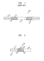
- Figure 1 shows a fiber device 10 in which a GRIN fiber lens 11 is fused to a terminal end 12 of an optical fiber 13.
- the GRIN fiber lens 11 expands and collimates the light beam emitted by the optical fiber 13.
- the GRIN fiber lens 11 improves the optical coupling between optical fiber 13 and fiber device 15 as compared to the coupling that would otherwise exist between the fiber 13 and device 15 due to diffraction.
- the GRIN fiber lens 11 reduces diffraction losses when the optical fiber 13 is optically coupled to another optical fiber.
- the beam diameter variations provide a measure of the lens' length.
- the length over which the variations in the beam diameter make two complete cycles is known as the pitch of the lens.
- lengths of GRIN lens are referred to in multiples of the pitch length, e.g., 1 ⁇ 2 pitch or 1 ⁇ 4 pitch.
- WO-A-01/11409 describes an optical imaging probe to be used with medial diagnostic devices where the probe has a single-mode optical fiber that is optically coupled to a lens of substantially the same diameter.
- US-A-6 172 817 describes a method for forming a GRIN rod lens where the glass in different regions is manufactured to avoid phase separation.
- US-A-6 131 413 describes a method of shrinking a tubular optical perform using a glassmaking lathe.
- EP-A-1 035 083 describes a method of preparing performs by removing or significantly reducing undesirable refractive index variations in the central portion of the fiber.
- EP-A-0 972 752 describes a unique and beneficial large optical perform made by a modified chemical vapor deposition process.
- JP-A-60 166 244 describes, in its abstract, a method of manufacturing a perform by collapsing a quartz tube while removing the innermost core.
- the embodiments of the invention include a GRIN fiber lens in which the refractive index has a radial profile.
- the GRIN fiber lens used in the invention increases the Rayleigh range of the emitted beam above that of a light beam emitted by a similar fiber attached to a conventional GRIN lens.
- the increased Rayleigh range improves beam collimation so that the fiber may couple to other optical devices over larger distance ranges.
- the GRIN fiber lens has a silica-glass core whose refractive index has a radially graded profile.
- the profile has negative radial second derivatives with average magnitudes in cores of less than about 1.7 ⁇ 10 -6 microns -2 times the value of the refractive index on the axis of the GRIN fiber lens. Henceforth, microns are written as ⁇ m.
- Figure 2 shows an optical fiber device 16 in which an optical fiber 17 is end-coupled to a GRIN fiber lens 18, e.g., fused or glued to the fiber 17.
- the GRIN fiber lens 18 and optical fiber 17 are co-axial and have similar or equal outer diameters whose values are in the range of about 100 ⁇ m to about 135 ⁇ m, e.g., 125 ⁇ m.
- the GRIN fiber lens 18 collimates a light beam 19 emitted from the end of the optical fiber 17 thereby decreasing the numerical aperture below that of a bare optical fiber.
- the GRIN fiber lens 18 is also able to focus an incident light beam into the end 20 of the optical fiber 17.
- Exemplary optical fibers 17 include single-mode and multi-mode fibers.
- the GRIN fiber lenses 18 used in the invention have refractive indexes whose radial profiles differ significantly from those of conventional GRIN fiber lenses.
- the radial profiles enable decreased numerical apertures and increased Rayleigh ranges for fiber device 16 as compared to values of the same quantities in conventional fiber device 10 of Figure 1.
- the decreased numerical aperture implies that an appropriate length GRIN fiber lens 18 would cause less diffraction and a lower power density in emitted light beam 19 than in the light beam 14 emitted by conventional fiber device 10.
- the increased Rayleigh range implies that emitted beam 19 is better collimated than the beam 14.
- the improved properties of the emitted beam 19 facilitate transverse alignments required to end-couple the fiber device 16 to another fiber device (not shown).
- GRIN fiber lens 18 has an end face 21 that is angle cleaved to reduce back reflections of light into optical fiber 17.
- a normal vector to the end-face 21 is preferably cleaved at an angle 1 ° - 2 ° or less with respect to the axis of the GRIN fiber lens 18. This cleave angle is smaller than a typical cleave angle of about 8 ° used to lower reflections from its end face back into the optical fiber (not shown).
- the beam expansion provided by the GRIN fiber lens 18 lowers the amount of angle cleave needed to produce an equivalent reduction in back reflections into the fiber 17.
- the GRIN fiber lens 18 has a circular core 22 and an annular cladding 24 that surrounds the core 22.
- the refractive index varies with the radial distance from the axis of the GRIN fiber lens 18.
- the refractive index is constant and has a lower value than in the core 22.
- the GRIN fiber lens has an outer diameter of about 125 ⁇ m. The outer diameter is the same as that of conventional GRIN fiber lens 11 shown in Figure 1. But, the conventional GRIN fiber lens and that used in the invention 11, 18 have different radial refractive index profiles due to differences in density distributions of dopant atoms in their cores.
- Exemplary dopants include germanium (Ge), aluminum (Al), phosphorus (P), and fluorine (F).
- Figure 3A shows radial profiles 26 and 27 of Ge-dopant densities in conventional GRIN fiber lens 11 and in the GRIN fiber lens 18, respectively.
- the Ge-dopant density has a radial profile that is largest on the central axis and curved concave downwards. The profile does not have an axial density dip, i.e., unlike some conventional GRIN fiber lenses (not shown).
- the curvature of the radial profile of the Ge-dopant has a smaller average magnitude in the core 22 of the GRIN fiber lens 18 than in the core of conventional GRIN fiber lens 11.
- the Ge-dopant densities are lower than in the fiber cores and are constant with respect to radial distance from the fiber axes.
- the boundaries between core and cladding, i.e., at radial distances of R c and R c ', are characterized by abrupt changes in the Ge-dopant densities and/or radial gradients of the densities.
- the core diameter is larger in the GRIN fiber lens 18 than in conventional GRIN fiber lens 11, i.e., R c ' > R c .
- Increasing the core diameter increases the Rayleigh range of fiber device 16 when a GRIN fiber lens 18 of appropriate length is used therein.
- Exemplary embodiments of the GRIN fiber lens 18 have an outer diameter of about 125 ⁇ m, and a core 22 with a diameter of about 85 ⁇ m, preferably 100 ⁇ m or more, and more preferably 105 ⁇ m or more. In some GRIN fiber lenses 18, cladding is absent so that the core has a diameter of about 125 ⁇ m.
- Figure 3B shows refractive index profiles 28 and 29 that correspond to the Ge-dopant density profiles 26 and 27 of GRIN fiber lenses 11 and 18, respectively.
- the radial profiles 28, 29 are concave down in the core 22.
- the radial profiles 28, 29 also show that the GRIN fiber lens 18 used in the invention has a refractive index whose radial profile has a significantly more gentle variation than in the conventional GRIN fiber lens 11.
- a parameter "g” measures the radial curvature of the refractive index profile in the core of a GRIN fiber lens.
- r 0
- "r" is radial distance for the axis of the GRIN fiber lens
- no is the value of the refractive index on the axis of the GRIN fiber lens
- P(r) is the value of the refractive index at the distance "r" from.the axis of the fiber lens.
- the GRIN fiber lens 18 has a refractive index profile that has a gentler radial variation over the lens' core.
- Refractive index profiles of the GRIN fiber lens 18 typically, have radial curvatures that are smaller in magnitude than those disclosed in Table 1 of EMKEY, (supra).
- magnitudes of the radial curvature of refractive index profile for embodiments of the GRIN fiber lens 18 are, at least, twice as small as values for the same quantity that are disclosed in EMKEY.
- Exemplary GRIN fiber lens 18 have a "g" that is less than 1.7 ⁇ 10 -6 ⁇ m -2 , preferable less than about 0.9 ⁇ 10 -6 ⁇ m -2 and more preferably less than about 5.0 ⁇ 10 -7 ⁇ m -2 .
- values of "g" are selected from the range 1.7 ⁇ 10 -6 ⁇ m -2 to 5.0 ⁇ 10 -7 ⁇ m -2 and preferably in the range 0.9 ⁇ 10 -6 ⁇ m -2 to 5.0 ⁇ 10 -7 ⁇ m -2 to provide good beam collimation.
- Exemplary GRIN fiber lens 18 have core index profiles that vary approximately quadratically in the distance from the lens axis. But, other embodiments of the GRIN fiber lens 18 have non-quadratic index profiles.
- the GRIN fiber lens 18 has a wider core 22 than the conventional GRIN fiber lens 11.
- the wider core 22 and the smaller value of the parameter "g" enable the GRIN fiber lens 18 of appropriate length to produce a beam with a wider cross section and a lower energy density when used as a beam collimator.
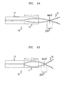
- Figures 4A and 4B show light beams 31, 32 emitted by fiber devices 16', 10' of the types shown in Figures 1 and 2.
- the fiber devices 16', 10' have GRIN fiber lenses 18', 11' with equal pitches, e.g., 5/16 pitch, but different refractive index profiles.
- the profile in the lens 18' significantly increases the Rayleigh range, RR, of the fiber device 16' above the Rayleigh range, RR', of the conventional device 10'.
- the increased Rayleigh range results from a more gradual beam expansion in the GRIN fiber lens 18' as compared to the beam expansion in the conventional GRIN fiber lens 11.
- Figures 4A and 4B show that making the radial curvature in refractive index of a GRIN fiber lens smaller than in conventional GRIN fiber lenses significantly reduces the divergence of the emitted beam for a given pitch.
- the Rayleigh range determines the distance range over which an optical device can couple to a fiber device without substantial losses.
- the larger Rayleigh range in the fiber device 16' makes a larger set of distances available for end-coupling to such a device than are available for the conventional fiber device 10'.
- GRIN lenses of equal pitch ordinarily have equal products of g 1/2 times the lens-length. Since the GRIN fiber lenses 18 have smaller g-values, the GRIN fiber lenses 18 are ordinarily longer than conventional GRIN fiber lenses 11 of equal pitch. The longer lengths make the GRIN fiber lenses 18 easier to handle, align, and fuse to optical fibers than the conventional GRIN fiber lenses 11. The increased lengths also reduce collimation errors associated with cleaving errors that occur during production of the GRIN fiber lenses 18.
- Figure 5 is a flow chart for a method 100 of fabricating a GRIN fiber lens of doped silica-glass through modified chemical vapor deposition (MCVD). MCVD construction of optical fibers is described in U.S. Patent 4,909,816 and 4,217,027 .
- the fabrication method 100 includes forming an improved GRIN preform and then, using the improved GRIN preform to make the GRIN fiber lenses, e.g., GRIN fiber lenses 18 of Figure 2.
- a time-varying partial pressure of dopant gases is bled into the gas mixture used to deposit silica-glass on the inside of the cladding tube.
- dopants include Ge, Al, P, and F.
- Introduction of one or more of these dopants into the silica-glass changes the refractive index of the glass.
- the partial pressure of dopant gas is varied during the MCVD process to produce a non-trivial radial profile of dopant atoms in the final silica-glass preform
- the radial profile in dopant atoms produces a selected radially graded refractive index in the final preform.
- Exemplary profiles for the dopant density and the refractive index have profiles with concave downward or negative radial curvature.
- the index profile varies as the square of the distance from the preform's axis in the core of the preform, e.g., profiles 27, 29 of Figures 3A and 3B.
- Other radial profiles may be obtained by suitably altering the time-variation of the partial pressure of dopant atoms during the MCVD.
- Non-quadratic profiles in GRIN fibers are capable of reshaping of light beams therein as is known to those of skill in the art.
- the method 100 includes using the tube produced by the internal deposition to form the rod-like preform.
- heat is applied to partially collapse the tube of doped silica-glass (step 104).
- the heating includes making repeated passes of the tube through a hot zone of a furnace. The heating is stopped prior to totally blocking the axial channel in the tube with glass.
- a silica-glass etchant mixture is passed through the axial channel to remove several layers of glass from the axis of the tube (step 106).
- An exemplary gaseous etchant mixture includes C 2 F 7 , O 2 , and Cl 2 .
- Other gaseous etchant mixtures include HF.
- the removed layers have lower dopant concentrations than adjacent outer layers of silica-glass, because dopants vaporize and are lost through the tube's axial canal during the heating used to collapse the tube. If these layers with lower dopant densities were not removed, the final preform would have an axial dip in dopant density and a corresponding axial dip in refractive index. The axial dip in refractive index interfered the operation of some conventional GRIN fiber lenses.
- the tube is externally heated to finish its collapse to a rod-like preform of doped silica glass (step 108).
- etchants are applied to the outer surface to remove a selected thickness of cladding tube from the outside of the preform (step 110). Removing a portion of the cladding tube enables subsequent drawing of glass fibers with less or no cladding, e.g., see profiles 27 and 29 in Figures 3A and 3B.
- These thin-clad or non-clad fibers are advantageous for GRIN fiber lenses, because such fibers enable an optical beam to expand over a larger portion of the cross section of the final GRIN fiber. Spreading the beam over a larger cross section decreases the associated numerical aperture and decreases power densities so that defects on the end surface of the lens or on the target of the emitted beam are less likely to cause component damage.
- Fabrication of GRIN fiber lenses also includes using a standard fiber drawing furnace to draw GRIN fiber from the graded-index preform (step 112). After cooling, one end of the drawn GRIN fiber is fused to one end of a standard fiber, i.e., a fiber with a non-graded index core (step 114). To fuse the GRIN and standard fibers, the ends of the two fibers are heated with an electrical arc or a tungsten filament in an argon environment while the ends are appropriately aligned and positioned adjacent each other.
- the GRIN fiber is cleaved to produce an optical lens with a desired length (step 116).
- the final attached GRIN fiber lenses has a pitch of 1 ⁇ 4, 1 ⁇ 2, or any other desired length and is fused to the fiber on which it functions as a beam collimator and expander.
- the cleaving is often performed along a direction that is not perpendicular to the axis of the GRIN fiber.
- cleaving the fiber's end face at an 8 degree angle with respect to a direction perpendicular to the fiber's axis significantly reduces back reflections.
- this cleaving angle can be reduced to less than 8 degrees from a direction perpendicular to the lens axis to achieve the same reduction in back reflections into an attached optical fiber, e.g., a preferred cleave angle is about 0.5 -2 degrees.
- the method 100 produces GRIN fiber lenses, e.g. lens 18 of Figure 2, that have lower refractive powers per unit length than conventional GRIN fiber lenses, e.g., lens 11 of Figure 1.
- the GRIN fiber lenses used in the invention are significantly longer than conventional GRIN fiber lenses having the same optical power.
- the longer lenses collimate light better and are easier to manipulate during device construction.
- Exemplary GRIN fiber lenses with low radial dopant gradients have full pitch lengths of about 2, 3, or 4-20 mm.
- the GRIN fiber lens 18 of Figure 2 can also be made by vapor axial deposition (VAD), outer vapor deposition (OVD), and sol-gel processes that are known to those of skill in the art. Such processes are also able to avoid creating an axial dip in refractive index in the final GRIN fiber lens.
- VAD vapor axial deposition
- OLED outer vapor deposition
- sol-gel processes that are known to those of skill in the art. Such processes are also able to avoid creating an axial dip in refractive index in the final GRIN fiber lens.
- Various embodiments provide optical fiber devices that are described below.
- the various devices described use GRIN fiber lens 18 of Figure 2.
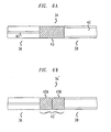
- Figure 6A shows a mode converter 34 that couples a pair of optical fibers 36, 38 having different fundamental or higher propagating modes.
- the optical fibers 36, 38 have cores of different diameters or have refractive index jumps of different sizes across core-cladding boundaries.
- GRIN fiber lens 43 is attached to the ends of the optical fibers 36, 38.
- the GRIN fiber lens 43 is either fused directly to the optical fibers 36, 38 or joined to the fibers 36, 38 by a glue layer (not shown) whose thickness is not greater than the width of the cores of fibers 36,38.
- optical fibers 36, 38 have different core diameters and/or refractive index jumps, the fibers 36, 38 have propagating modes, e.g., fundamental modes, with different sizes.
- the size of a propagating mode is defined as the mode's full-diameter between half-maximum amplitude values. Due to the different sizes of the propagating modes, coupling the optical fibers 36, 38 directly would produce a significant coupling loss of optical energy, i.e., a splice loss.
- GRIN fiber lens 43 is positioned between optical fibers 36, 38 and is selected to expand the narrower propagating mode of optical fiber 36 to have a larger diameter that equals that of the propagating mode of the optical fiber 38. Designing the GRIN fiber lens 43 to produce the appropriate size conversion entails selecting an appropriate lens length. One of skill in the art would know how to select the length of GRIN fiber lens 43 based on the amount of magnification needed to convert the size of the propagating mode of one fiber 36 into that of the propagating mode of the other fiber 38.
- the mode converter 34 couples a waveguide other than an optical fiber to optical fiber 38.
- Figure 6B shows a specific embodiment 34' of the mode converter 34 of Figure 6A.
- GRIN fiber lens 43' is a compound lens made of a sequence of GRIN fiber lens elements 43A, 43B.
- the first element 43A is fused directly to the end of optical fiber 36, and the last element 43B is fused directly to the end of optical fiber 38.
- Exemplary GRIN elements 43A and 43B are fused together and have different refractive index profiles and lengths. The lengths and index profiles of the two lens elements 43A, 43B are selected to better optically couple the fibers 36, 38.
- the first GRIN element 43A expands the light beam emitted by fiber 36, and the second element 43B focuses the beam waist to the size of the propagating mode in the fiber 38.
- Figure 7A shows a 1x2 micro-optical router 46.
- the router 46 includes an input optical fiber 48, output optical fibers 50, 52, and a movable reflector 54 for directing light from the input fiber 48 to a selected one of the output fibers 50, 52.
- the terminal ends of the optical fibers 48, 50, 52 are fused to GRIN fiber lenses 49, 49', 49", e.g., identical GRIN fiber lenses.
- the GRIN fiber lens 49 functions to collimate or focus the emitted light beam from fiber 48.
- the GRIN fiber lenses 49', 49" function to collect light and couple the collected light into the associated optical fibers 50, 52.
- the output optical fibers 50, 52 are located so that the waist of the beam emitted by the input optical fiber 48 is at the midpoint of the optical path between the input and output optical fibers 48, 50, 52.
- the reflecting surface of reflector 54 is located at the beam waist to within about a Rayleigh range when positioned to reflect light to the output optical fiber 50.
- reflector 54 is moved in or out of the path of the light beam emitted by optical fiber 48.
- the reflector 54 is fixed to a micro-electro-mechanical (MEM) device 56 that moves the reflector 54 in and out of the beam's optical path in response to electrical signals applied to the MEM device 56.
- MEM micro-electro-mechanical
- the GRIN fiber lenses 49, 49', 49" improve beam collimation and collection so that terminal ends 58, 60, 62 can be separated by distances that are large enough to enable insertion and removal of reflector 54 in routing region 64.
- router 46 based on the GRIN fiber lenses 18 of Figures 2, 3A-3B, and 4A, better beam collimation enables distances between terminal ends 58, 60, 62 to be as large as about 9 mm.
- the GRIN fiber lenses 49, 49', 49" reduce optical coupling losses to less than about 0.5 decibels (dB) and preferably to less than about 0.2 dB - 0.05 dB.
- larger inter-fiber spaces involve more serious fiber device alignment issues.
- the micro-router 46 has an overall size, S, that is much smaller than the overall size of an analogous router in which the GRIN fiber lenses 49, 49', 49" are replaced by conventional lenses with curved refractive surfaces.
- the lenses with curved refractive surfaces have larger diameters than the GRIN fiber lenses 49, 49', 49".
- the larger lens diameters require positioning the ends of the input and output fibers at larger separations in such a router than in the micro-router 46.
- the lenses with curved refractive surfaces also typically produce larger diameter collimated beams in the routing region than the fused GRIN fiber lenses 49 of micro-router 46.
- the larger beam diameters necessitate a larger reflective surface on the routering reflector of the router whose lenses have curved refractive surfaces than would be needed on the reflector 56 of the micro-router 46.
- the distance, S, characteristic of separations between GRIN lenses 49, 49', 49" has a value in the range of about 1-3 times the fiber diameter to about 1-3 times the Rayleigh range, e.g., less than about 1 mm.
- the small size of the region 64 between the lenses 49, 49', 49" is achieved in part, because diameters of the attached GRIN fiber lenses 49, 49', 49" are small and in part, because the reflective surface on reflector 54 has a small beam acceptance window.
- the acceptance window for reflecting the input beam can be less than the fiber diameter, because the GRIN fiber lens 49 produces a beam waist that is smaller than the diameter of fiber 48.
- Both the small diameter GRIN fiber lenses 49, 49', 49" and the smallness of reflector 54 enable the router 46 to be much smaller than routers that use lenses with curved refractive surfaces.
- Figure 7B shows an alternate embodiment 46' of the router 46 shown in Figure 7A.
- the fibers 48, 50, 52 are adjacent and located in a linear array 68.
- a single rotatable reflector 54' e.g., a MEMS controlled reflector, selectively routes light from the fiber 48 to either the fiber 50 or the fiber 52.
- the axes the fibers 50 and 52 are slightly tilted with respect to the axis of the fiber 48 to insure that light from the reflector 56' parallel to the axis of the fibers 50, 52.
- Arranging the fibers 48, 50, 52 in array 68 makes the width of the router 46' roughly equal to the width, W, of the array 68.
- the small diameters and fine collimation of GRIN fiber lenses 49, 49', 49" enable packing the fibers 48, 50, 52 closely in the array 68.
- embodiments of the router 46 can have a width, W, that is much smaller than the width of a similar-form router in which lenses with curved refractive surfaces replace the GRIN fiber lenses 49, 49', 49".
- Figure 7C shows an embodiment of an optical device 46" that couples three optical fibers 48, 50, 52 based on light polarization, light wavelength, or relative fiber position.
- the optical fibers 48, 50, 52 have attached GRIN fiber lenses 49, 49', 49" that collimate and collect light.
- the device 46" includes an optical element 54' that transmits light between the optical fibers 48, 50, 52, e.g., in a manner that depends on polarization or wavelength.
- optical device 54' includes a polarizing beamsplitter, a grating, an optical circulator, or a wavelength selective reflector such as a Bragg grating.
- Figure 8 shows a 1xN micro-optical router 70 that includes an input optical fiber 72, an output array 73 of N output optical fibers 74 1 -74 N , and a reflector 76.
- the optical fibers 72, 74 1 -74 N are single-mode fibers to which terminal GRIN fiber lenses 77 0 -77 N have been fused.
- the light beam 78 from the input optical fiber 72 intersects the reflector 76 near the waist of the beam 78, i.e., within 1 ⁇ 2 a Rayleigh range.
- Exemplary reflectors 76 include mirrors that move or rotate and diffraction gratings that reflect light in a wavelength dependent manner.
- the router may be a spectrally sensitive demultiplexer for a wavelength division multiplexed network.
- the GRIN fiber lenses 77 0 -77 N expand and collimate the light beam 78 of the input optical fiber 72 and focus the light beam 78 into the output optical fibers 74 1 -74 N . Due to the GRIN fiber lenses 77 0 -77 N , the output array 73 of optical fibers 74 1 -74 N and input optical fiber 72 can be separated by an optical path that is long enough to enable insertion of bulk reflector 76 into the path without significant coupling losses. For the router 70 coupling losses are typically less than about 0.5 dB- 0.2 dB and preferably less than about 0.1 dB.
- GRIN fiber lens 77 0 focuses the beam from fiber 72 onto a reflective acceptance window on the reflector 76. Perpendicular to direction D, the diameter of the acceptance window is less than the fiber diameter. Also, the use of the GRIN fiber lenses 77 0 -77 N enables an increased fiber packing density in the array 73 without interference between light beams reflected towards different ones of the fibers 74 1 -74 N . Finally, the use of GRIN fiber lens 77 0 enables the acceptance window and overall size of reflector 76 to be smaller than that of the reflector that would otherwise be needed in a router using lenses curved refractive surfaces (not shown). Thus, using the GRIN fiber lenses 77 0 -77 N enables greater miniaturization in micro-router 70 than in a fiber router based on lenses with curved refractive surfaces.
- Nx1 routers use the GRIN fiber lens 18 of Figure 2 to construct Nx1 routers (not shown) by methods that would be obvious to one of skill in the art in light of the above-disclosure.
- a 2x1 router can be constructed by exchanging designations of input and output for fibers 48, 50, 52 in 1x2 micro-router 46 of Figure 7A.
- Figure 9 is a top view of an NxM optical router 80.
- the router 80 includes an array 81 of N input optical fibers, 82 1 -82 N , and an array 83 of M output optical fibers, 84 1 -84 M .
- the fibers 82 1 -82 N , 84 1 -84 M have GRIN fiber lenses 85 1 -85 N , 86 1 -86 M fused to terminal ends thereof.
- the GRIN fiber lenses 85 1 -85 N , 86 1 -86 M provide beam collimation and collection functions analogous those previously described in relation to GRIN fiber lenses 49, 49', 49" of Figure 7A.
- exemplary reflectors 89 R1 -89 RN include wavelength-selective reflectors, e.g., gratings, and wavelength insensitive reflectors. Properly aligning the reflectors 88 R1 -88 RN routes light from individual ones of the input fibers 82 1 -82 N to selected ones of the output fibers, 84 1 -84 M .
- the reflectors 88 R1 -88 RN are operated by MEMs devices 89 1 -89 N and have acceptance windows for input beams whose diameters are smaller than the inter-fiber spacing, IFS, of array 81.
- the fiber packing densities in the arrays 81, 83 can be increased above fiber packing densities of an NxM fiber router in which lenses with curved refractive surfaces (not shown) replace the GRIN fiber lenses 85 1 -85 N , 86 1 -86 M of Figure 9.
- sizes of reflective surfaces of reflectors 88 F1 -88 FN , 89 R1 -89 RN in the router 80 are smaller than sizes of reflective surfaces of reflectors in routers based on lenses with curved refractive surfaces, because the beam diameters produced by the GRIN fiber lenses 85 1 -85 N are small. Both effects enable the new NxM to be smaller than an NxM router based on lenses with curved refractive surfaces.
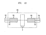
- Figure 10 shows a micro-optical device 90 that is located in-line between ends 91, 93 of optical fibers 92, 94.
- Exemplary micro-optical devices 90 include wavelength-sensitive add/drop modules, polarizers, polarization rotators, one-way optical isolators, and controllable optical attenuators.
- the ends 91, 93 of the optical fibers 92, 94 are fused to GRIN fiber lenses 96, 98.
- the GRIN fiber lens 96 collimates light emitted by the optical fiber 92.
- the GRIN fiber lens 98 focuses received light into the optical fiber 94.
- the micro-optical device 90 has an approximate thickness, d, that, is not greater than the Rayleigh range associated with the GRIN fiber lenses 96, 98. For such a thickness, the GRIN fiber lenses 96, 98 reduce diffraction-related coupling losses.
Landscapes
- Physics & Mathematics (AREA)
- Chemical & Material Sciences (AREA)
- Engineering & Computer Science (AREA)
- General Physics & Mathematics (AREA)
- Optics & Photonics (AREA)
- General Life Sciences & Earth Sciences (AREA)
- Life Sciences & Earth Sciences (AREA)
- General Chemical & Material Sciences (AREA)
- Chemical Kinetics & Catalysis (AREA)
- Geochemistry & Mineralogy (AREA)
- Manufacturing & Machinery (AREA)
- Materials Engineering (AREA)
- Organic Chemistry (AREA)
- Optical Couplings Of Light Guides (AREA)
- Optical Fibers, Optical Fiber Cores, And Optical Fiber Bundles (AREA)
- Mechanical Light Control Or Optical Switches (AREA)
Description
- This invention relates to optical devices and graded refractive index lenses.
- A graded refractive index (GRIN) lens has a refractive index whose value varies with radial distance from the axis of the lens. The non-trivial variation in refractive index causes light refraction and gives the GRIN lens focussing capabilities that are similar to those of an ordinary lens. Therefore, many optical devices employ GRIN or ordinary lenses interchangeably.
- Many optical devices use lenses to focus, collimate, or expand light beams. Figure 1 shows a
fiber device 10 in which aGRIN fiber lens 11 is fused to aterminal end 12 of anoptical fiber 13. TheGRIN fiber lens 11 expands and collimates the light beam emitted by theoptical fiber 13. TheGRIN fiber lens 11 improves the optical coupling betweenoptical fiber 13 andfiber device 15 as compared to the coupling that would otherwise exist between thefiber 13 anddevice 15 due to diffraction. TheGRIN fiber lens 11 reduces diffraction losses when theoptical fiber 13 is optically coupled to another optical fiber. - Since the diameter of a light beam varies along the axis of a GRIN lens, the beam diameter variations provide a measure of the lens' length. The length over which the variations in the beam diameter make two complete cycles is known as the pitch of the lens. Typically, lengths of GRIN lens are referred to in multiples of the pitch length, e.g., ½ pitch or ¼ pitch.
- W.L. Emkey, et al., Analysis and Evaluation of Graded-Index Fiber-Lenses, JOURNAL OF LIGHTWAVE TECHNOLOGY, Vol. LT-5, 1987, pages 1156-1164 (EMKEY), reports on the coupling efficiency between two fiber lenses fused to their end faces and addresses applications in which optical components are inserted between the two fibers.
-
WO-A-01/11409 -
US-A-6 172 817 describes a method for forming a GRIN rod lens where the glass in different regions is manufactured to avoid phase separation. -
US-A-6 131 413 describes a method of shrinking a tubular optical perform using a glassmaking lathe. -
EP-A-1 035 083 describes a method of preparing performs by removing or significantly reducing undesirable refractive index variations in the central portion of the fiber. -
EP-A-0 972 752 describes a unique and beneficial large optical perform made by a modified chemical vapor deposition process. -
JP-A-60 166 244 - Apparatus and a method according to the invention are as set out in the independent claims. Preferred forms are set out in the dependent claims.
- The embodiments of the invention include a GRIN fiber lens in which the refractive index has a radial profile. When attached to an end of an optical fiber, the GRIN fiber lens used in the invention increases the Rayleigh range of the emitted beam above that of a light beam emitted by a similar fiber attached to a conventional GRIN lens. The increased Rayleigh range improves beam collimation so that the fiber may couple to other optical devices over larger distance ranges.
- In the invention, the GRIN fiber lens has a silica-glass core whose refractive index has a radially graded profile. The profile has negative radial second derivatives with average magnitudes in cores of less than about 1.7 × 10⁻⁶ microns-2 times the value of the refractive index on the axis of the GRIN fiber lens. Henceforth, microns are written as µm.
-
- Figure 1 is a cross-sectional view of a fiber device that uses a conventional GRIN fiber lens to end-couple two optical fibers;
- Figure 2 is a cross-sectional view of a fiber device in which an optical fiber is fused to an embodiment of a GRIN fiber lens;
- Figure 3A shows radial profiles of germanium dopant densities in a conventional GRIN fiber lens and a GRIN fiber lens used in the invention;
- Figure 3B shows radial profiles of refractive indexes for the GRIN fiber lenses of Figure 3A;
- Figures 4A and 4B illustrate beam collimation in fiber devices with the GRIN fiber lens used in the invention and with conventional GRIN fiber lenses, respectively;
- Figure 5 is a flow chart for a method of fabricating the fiber device of Figure 2.
- Figure 6A is a cross-sectional view of a mode converter;
- Figure 6B is a cross-sectional view of a mode converter that uses a compound GRIN fiber lens;
- Figure 7A is a top view of a 1x2 micro-optical router;
- Figure 7B is a top view of another topology for a 1x2 micro-optical router;
- Figure 7C is a top view of a device that optically couples three optical fibers;
- Figure 8 is a cross-sectional view of a 1xN micro-optical router;
- Figure 9 is a top view of an N×M micro-optical router; and
- Figure 10 is a cross-sectional view of an optical fiber with an in-line optical device.
- In the Figures, like reference numbers refer to functionally similar features.
- Figure 2 shows an
optical fiber device 16 in which anoptical fiber 17 is end-coupled to aGRIN fiber lens 18, e.g., fused or glued to thefiber 17. TheGRIN fiber lens 18 andoptical fiber 17 are co-axial and have similar or equal outer diameters whose values are in the range of about 100 µm to about 135 µm, e.g., 125 µm. TheGRIN fiber lens 18 collimates alight beam 19 emitted from the end of theoptical fiber 17 thereby decreasing the numerical aperture below that of a bare optical fiber. TheGRIN fiber lens 18 is also able to focus an incident light beam into theend 20 of theoptical fiber 17. - Exemplary
optical fibers 17 include single-mode and multi-mode fibers. - The
GRIN fiber lenses 18 used in the invention have refractive indexes whose radial profiles differ significantly from those of conventional GRIN fiber lenses. The radial profiles enable decreased numerical apertures and increased Rayleigh ranges forfiber device 16 as compared to values of the same quantities inconventional fiber device 10 of Figure 1. The decreased numerical aperture implies that an appropriate lengthGRIN fiber lens 18 would cause less diffraction and a lower power density in emittedlight beam 19 than in thelight beam 14 emitted byconventional fiber device 10. The increased Rayleigh range implies that emittedbeam 19 is better collimated than thebeam 14. The improved properties of the emittedbeam 19 facilitate transverse alignments required to end-couple thefiber device 16 to another fiber device (not shown). - In some embodiments of
fiber device 16,GRIN fiber lens 18 has anend face 21 that is angle cleaved to reduce back reflections of light intooptical fiber 17. In particular, a normal vector to the end-face 21 is preferably cleaved at anangle 1 ° - 2 ° or less with respect to the axis of theGRIN fiber lens 18. This cleave angle is smaller than a typical cleave angle of about 8 ° used to lower reflections from its end face back into the optical fiber (not shown). The beam expansion provided by theGRIN fiber lens 18 lowers the amount of angle cleave needed to produce an equivalent reduction in back reflections into thefiber 17. - The
GRIN fiber lens 18 has acircular core 22 and anannular cladding 24 that surrounds thecore 22. In thecore 22, the refractive index varies with the radial distance from the axis of theGRIN fiber lens 18. In thecladding 24, the refractive index is constant and has a lower value than in thecore 22. The GRIN fiber lens has an outer diameter of about 125 µm. The outer diameter is the same as that of conventionalGRIN fiber lens 11 shown in Figure 1. But, the conventional GRIN fiber lens and that used in theinvention - Figure 3A shows
radial profiles GRIN fiber lens 11 and in theGRIN fiber lens 18, respectively. In thecore 22 of theGRIN fiber lens 18, the Ge-dopant density has a radial profile that is largest on the central axis and curved concave downwards. The profile does not have an axial density dip, i.e., unlike some conventional GRIN fiber lenses (not shown). The curvature of the radial profile of the Ge-dopant has a smaller average magnitude in thecore 22 of theGRIN fiber lens 18 than in the core of conventionalGRIN fiber lens 11. In the claddings ofGRIN fiber lenses - The boundaries between core and cladding, i.e., at radial distances of Rc and Rc', are characterized by abrupt changes in the Ge-dopant densities and/or radial gradients of the densities. The core diameter is larger in the
GRIN fiber lens 18 than in conventionalGRIN fiber lens 11, i.e., Rc' > Rc. Increasing the core diameter increases the Rayleigh range offiber device 16 when aGRIN fiber lens 18 of appropriate length is used therein. Exemplary embodiments of theGRIN fiber lens 18 have an outer diameter of about 125 µm, and a core 22 with a diameter of about 85 µm, preferably 100 µm or more, and more preferably 105 µm or more. In someGRIN fiber lenses 18, cladding is absent so that the core has a diameter of about 125 µm. - Figure 3B shows refractive index profiles 28 and 29 that correspond to the Ge-
dopant density profiles GRIN fiber lenses core 22. - The radial profiles 28, 29 also show that the
GRIN fiber lens 18 used in the invention has a refractive index whose radial profile has a significantly more gentle variation than in the conventionalGRIN fiber lens 11. A parameter "g" measures the radial curvature of the refractive index profile in the core of a GRIN fiber lens. In particular, the parameter g is defined as:
- The
GRIN fiber lens 18 has a refractive index profile that has a gentler radial variation over the lens' core. Refractive index profiles of theGRIN fiber lens 18 typically, have radial curvatures that are smaller in magnitude than those disclosed in Table 1 of EMKEY, (supra). Typically, magnitudes of the radial curvature of refractive index profile for embodiments of theGRIN fiber lens 18 are, at least, twice as small as values for the same quantity that are disclosed in EMKEY. ExemplaryGRIN fiber lens 18 have a "g" that is less than 1.7 × 10⁻⁶ µm-2, preferable less than about 0.9 × 10⁻⁶ µm-2 and more preferably less than about 5.0 × 10⁻⁷ µm-2. For 125 µm - diameterGRIN fiber lenses 18, values of "g" are selected from the range 1.7 × 10⁻⁶ µm-2 to 5.0 × 10⁻⁷ µm-2 and preferably in the range 0.9 × 10⁻⁶ µm-2 to 5.0 × 10⁻⁷ µm-2 to provide good beam collimation. - Exemplary
GRIN fiber lens 18 have core index profiles that vary approximately quadratically in the distance from the lens axis. But, other embodiments of theGRIN fiber lens 18 have non-quadratic index profiles. - Referring again to Figure 2, the
GRIN fiber lens 18 has awider core 22 than the conventionalGRIN fiber lens 11. Thewider core 22 and the smaller value of the parameter "g" enable theGRIN fiber lens 18 of appropriate length to produce a beam with a wider cross section and a lower energy density when used as a beam collimator. - Figures 4A and 4B show light beams 31, 32 emitted by fiber devices 16', 10' of the types shown in Figures 1 and 2. The fiber devices 16', 10' have GRIN fiber lenses 18', 11' with equal pitches, e.g., 5/16 pitch, but different refractive index profiles. The profile in the lens 18' significantly increases the Rayleigh range, RR, of the fiber device 16' above the Rayleigh range, RR', of the conventional device 10'. The increased Rayleigh range results from a more gradual beam expansion in the GRIN fiber lens 18' as compared to the beam expansion in the conventional
GRIN fiber lens 11. In particular, Figures 4A and 4B show that making the radial curvature in refractive index of a GRIN fiber lens smaller than in conventional GRIN fiber lenses significantly reduces the divergence of the emitted beam for a given pitch. - The Rayleigh range determines the distance range over which an optical device can couple to a fiber device without substantial losses. The larger Rayleigh range in the fiber device 16' makes a larger set of distances available for end-coupling to such a device than are available for the conventional fiber device 10'.
- GRIN lenses of equal pitch ordinarily have equal products of g1/2 times the lens-length. Since the
GRIN fiber lenses 18 have smaller g-values, theGRIN fiber lenses 18 are ordinarily longer than conventionalGRIN fiber lenses 11 of equal pitch. The longer lengths make theGRIN fiber lenses 18 easier to handle, align, and fuse to optical fibers than the conventionalGRIN fiber lenses 11. The increased lengths also reduce collimation errors associated with cleaving errors that occur during production of theGRIN fiber lenses 18. - Figure 5 is a flow chart for a
method 100 of fabricating a GRIN fiber lens of doped silica-glass through modified chemical vapor deposition (MCVD). MCVD construction of optical fibers is described inU.S. Patent 4,909,816 and4,217,027 . Thefabrication method 100 includes forming an improved GRIN preform and then, using the improved GRIN preform to make the GRIN fiber lenses, e.g.,GRIN fiber lenses 18 of Figure 2. - To form the GRIN preform, layers of silica-glass are deposited inside a silica-glass cladding tube by MCVD (step 102). During the MCVD, a time-varying partial pressure of dopant gases is bled into the gas mixture used to deposit silica-glass on the inside of the cladding tube. Exemplary dopants include Ge, Al, P, and F. Introduction of one or more of these dopants into the silica-glass changes the refractive index of the glass. The partial pressure of dopant gas is varied during the MCVD process to produce a non-trivial radial profile of dopant atoms in the final silica-glass preform
- The radial profile in dopant atoms produces a selected radially graded refractive index in the final preform. Exemplary profiles for the dopant density and the refractive index have profiles with concave downward or negative radial curvature. Often, the index profile varies as the square of the distance from the preform's axis in the core of the preform, e.g., profiles 27, 29 of Figures 3A and 3B. Other radial profiles may be obtained by suitably altering the time-variation of the partial pressure of dopant atoms during the MCVD. Non-quadratic profiles in GRIN fibers are capable of reshaping of light beams therein as is known to those of skill in the art.
- The
method 100 includes using the tube produced by the internal deposition to form the rod-like preform. To form the rod-like preform, heat is applied to partially collapse the tube of doped silica-glass (step 104). In one embodiment, the heating includes making repeated passes of the tube through a hot zone of a furnace. The heating is stopped prior to totally blocking the axial channel in the tube with glass. - After partially collapsing the tube, a silica-glass etchant mixture is passed through the axial channel to remove several layers of glass from the axis of the tube (step 106). An exemplary gaseous etchant mixture includes C2F7, O2, and Cl2. Other gaseous etchant mixtures include HF. The removed layers have lower dopant concentrations than adjacent outer layers of silica-glass, because dopants vaporize and are lost through the tube's axial canal during the heating used to collapse the tube. If these layers with lower dopant densities were not removed, the final preform would have an axial dip in dopant density and a corresponding axial dip in refractive index. The axial dip in refractive index interfered the operation of some conventional GRIN fiber lenses.
- After the etching removal of several central layers of glass, the tube is externally heated to finish its collapse to a rod-like preform of doped silica glass (step 108).
- After cooling the preform, etchants are applied to the outer surface to remove a selected thickness of cladding tube from the outside of the preform (step 110). Removing a portion of the cladding tube enables subsequent drawing of glass fibers with less or no cladding, e.g., see
profiles - Fabrication of GRIN fiber lenses also includes using a standard fiber drawing furnace to draw GRIN fiber from the graded-index preform (step 112). After cooling, one end of the drawn GRIN fiber is fused to one end of a standard fiber, i.e., a fiber with a non-graded index core (step 114). To fuse the GRIN and standard fibers, the ends of the two fibers are heated with an electrical arc or a tungsten filament in an argon environment while the ends are appropriately aligned and positioned adjacent each other.
- Finally, the GRIN fiber is cleaved to produce an optical lens with a desired length (step 116). The final attached GRIN fiber lenses has a pitch of ¼, ½, or any other desired length and is fused to the fiber on which it functions as a beam collimator and expander.
- To reduce reflections from the face of the final fiber device back into the fiber, the cleaving is often performed along a direction that is not perpendicular to the axis of the GRIN fiber. In a non-GRIN optical fiber, cleaving the fiber's end face at an 8 degree angle with respect to a direction perpendicular to the fiber's axis significantly reduces back reflections. For a GRIN fiber lens, this cleaving angle can be reduced to less than 8 degrees from a direction perpendicular to the lens axis to achieve the same reduction in back reflections into an attached optical fiber, e.g., a preferred cleave angle is about 0.5 -2 degrees.
- The
method 100 produces GRIN fiber lenses,e.g. lens 18 of Figure 2, that have lower refractive powers per unit length than conventional GRIN fiber lenses, e.g.,lens 11 of Figure 1. Thus, the GRIN fiber lenses used in the invention are significantly longer than conventional GRIN fiber lenses having the same optical power. The longer lenses collimate light better and are easier to manipulate during device construction. Exemplary GRIN fiber lenses with low radial dopant gradients have full pitch lengths of about 2, 3, or 4-20 mm. - The
GRIN fiber lens 18 of Figure 2 can also be made by vapor axial deposition (VAD), outer vapor deposition (OVD), and sol-gel processes that are known to those of skill in the art. Such processes are also able to avoid creating an axial dip in refractive index in the final GRIN fiber lens. - Various embodiments provide optical fiber devices that are described below. The various devices described use
GRIN fiber lens 18 of Figure 2. - Figure 6A shows a
mode converter 34 that couples a pair ofoptical fibers optical fibers mode converter 34.GRIN fiber lens 43 is attached to the ends of theoptical fibers exemplary mode converters 34 theGRIN fiber lens 43 is either fused directly to theoptical fibers fibers fibers - Since
optical fibers fibers optical fibers - To reduce splice losses,
GRIN fiber lens 43 is positioned betweenoptical fibers optical fiber 36 to have a larger diameter that equals that of the propagating mode of theoptical fiber 38. Designing theGRIN fiber lens 43 to produce the appropriate size conversion entails selecting an appropriate lens length. One of skill in the art would know how to select the length ofGRIN fiber lens 43 based on the amount of magnification needed to convert the size of the propagating mode of onefiber 36 into that of the propagating mode of theother fiber 38. - In other embodiments, the
mode converter 34 couples a waveguide other than an optical fiber tooptical fiber 38. - Figure 6B shows a specific embodiment 34' of the
mode converter 34 of Figure 6A. In the mode converter 34', GRIN fiber lens 43' is a compound lens made of a sequence of GRINfiber lens elements 43A, 43B. Thefirst element 43A is fused directly to the end ofoptical fiber 36, and the last element 43B is fused directly to the end ofoptical fiber 38.Exemplary GRIN elements 43A and 43B are fused together and have different refractive index profiles and lengths. The lengths and index profiles of the twolens elements 43A, 43B are selected to better optically couple thefibers first GRIN element 43A expands the light beam emitted byfiber 36, and the second element 43B focuses the beam waist to the size of the propagating mode in thefiber 38. - Figure 7A shows a
1x2 micro-optical router 46. Therouter 46 includes an inputoptical fiber 48, outputoptical fibers movable reflector 54 for directing light from theinput fiber 48 to a selected one of theoutput fibers - The terminal ends of the
optical fibers GRIN fiber lenses GRIN fiber lens 49 functions to collimate or focus the emitted light beam fromfiber 48. TheGRIN fiber lenses 49', 49" function to collect light and couple the collected light into the associatedoptical fibers optical fibers optical fiber 48 is at the midpoint of the optical path between the input and outputoptical fibers reflector 54 is located at the beam waist to within about a Rayleigh range when positioned to reflect light to the outputoptical fiber 50. - To select a routing,
reflector 54 is moved in or out of the path of the light beam emitted byoptical fiber 48. Thereflector 54 is fixed to a micro-electro-mechanical (MEM) device 56 that moves thereflector 54 in and out of the beam's optical path in response to electrical signals applied to the MEM device 56. - The
GRIN fiber lenses reflector 54 inrouting region 64. In embodiments ofrouter 46 based on theGRIN fiber lenses 18 of Figures 2, 3A-3B, and 4A, better beam collimation enables distances between terminal ends 58, 60, 62 to be as large as about 9 mm. For these large inter-fiber distances, theGRIN fiber lenses - In some embodiments, the micro-router 46 has an overall size, S, that is much smaller than the overall size of an analogous router in which the
GRIN fiber lenses GRIN fiber lenses GRIN fiber lenses 49 ofmicro-router 46. The larger beam diameters necessitate a larger reflective surface on the routering reflector of the router whose lenses have curved refractive surfaces than would be needed on the reflector 56 of the micro-router 46. - In some embodiments of
micro-router 46, the distance, S, characteristic of separations betweenGRIN lenses region 64 between thelenses GRIN fiber lenses reflector 54 has a small beam acceptance window. The acceptance window for reflecting the input beam can be less than the fiber diameter, because theGRIN fiber lens 49 produces a beam waist that is smaller than the diameter offiber 48. Both the small diameterGRIN fiber lenses reflector 54 enable therouter 46 to be much smaller than routers that use lenses with curved refractive surfaces. - Figure 7B shows an alternate embodiment 46' of the
router 46 shown in Figure 7A. In router 46', thefibers linear array 68. A single rotatable reflector 54', e.g., a MEMS controlled reflector, selectively routes light from thefiber 48 to either thefiber 50 or thefiber 52. In some embodiments, the axes thefibers fiber 48 to insure that light from the reflector 56' parallel to the axis of thefibers - Arranging the
fibers array 68 makes the width of the router 46' roughly equal to the width, W, of thearray 68. The small diameters and fine collimation ofGRIN fiber lenses fibers array 68. Thus, embodiments of therouter 46 can have a width, W, that is much smaller than the width of a similar-form router in which lenses with curved refractive surfaces replace theGRIN fiber lenses - Figure 7C shows an embodiment of an
optical device 46" that couples threeoptical fibers optical fibers GRIN fiber lenses device 46" includes an optical element 54' that transmits light between theoptical fibers - Figure 8 shows a 1xN
micro-optical router 70 that includes an inputoptical fiber 72, anoutput array 73 of N output optical fibers 741-74N, and areflector 76. Theoptical fibers 72, 741-74N are single-mode fibers to which terminal GRIN fiber lenses 770-77N have been fused. Thelight beam 78 from the inputoptical fiber 72 intersects thereflector 76 near the waist of thebeam 78, i.e., within ½ a Rayleigh range. -
Exemplary reflectors 76 include mirrors that move or rotate and diffraction gratings that reflect light in a wavelength dependent manner. For example, the router may be a spectrally sensitive demultiplexer for a wavelength division multiplexed network. - The GRIN fiber lenses 770-77N expand and collimate the
light beam 78 of the inputoptical fiber 72 and focus thelight beam 78 into the output optical fibers 741-74N. Due to the GRIN fiber lenses 770-77N, theoutput array 73 of optical fibers 741-74N and inputoptical fiber 72 can be separated by an optical path that is long enough to enable insertion ofbulk reflector 76 into the path without significant coupling losses. For therouter 70 coupling losses are typically less than about 0.5 dB- 0.2 dB and preferably less than about 0.1 dB. - In
micro-optical router 70,GRIN fiber lens 770 focuses the beam fromfiber 72 onto a reflective acceptance window on thereflector 76. Perpendicular to direction D, the diameter of the acceptance window is less than the fiber diameter. Also, the use of the GRIN fiber lenses 770-77N enables an increased fiber packing density in thearray 73 without interference between light beams reflected towards different ones of the fibers 741-74N. Finally, the use ofGRIN fiber lens 770 enables the acceptance window and overall size ofreflector 76 to be smaller than that of the reflector that would otherwise be needed in a router using lenses curved refractive surfaces (not shown). Thus, using the GRIN fiber lenses 770-77N enables greater miniaturization inmicro-router 70 than in a fiber router based on lenses with curved refractive surfaces. - Other embodiments use the
GRIN fiber lens 18 of Figure 2 to construct Nx1 routers (not shown) by methods that would be obvious to one of skill in the art in light of the above-disclosure. For example, a 2x1 router can be constructed by exchanging designations of input and output forfibers 1x2 micro-router 46 of Figure 7A. - Figure 9 is a top view of an NxM
optical router 80. Therouter 80 includes anarray 81 of N input optical fibers, 821-82N, and anarray 83 of M output optical fibers, 841-84M. The fibers 821-82N, 841-84M have GRIN fiber lenses 851-85N, 861-86M fused to terminal ends thereof. The GRIN fiber lenses 851-85N, 861-86M provide beam collimation and collection functions analogous those previously described in relation toGRIN fiber lenses array 81. - By using attached GRIN fiber lenses 851-85N, 861-86M the fiber packing densities in the
arrays router 80 are smaller than sizes of reflective surfaces of reflectors in routers based on lenses with curved refractive surfaces, because the beam diameters produced by the GRIN fiber lenses 851-85N are small. Both effects enable the new NxM to be smaller than an NxM router based on lenses with curved refractive surfaces. - Figure 10 shows a
micro-optical device 90 that is located in-line between ends 91, 93 ofoptical fibers micro-optical devices 90 include wavelength-sensitive add/drop modules, polarizers, polarization rotators, one-way optical isolators, and controllable optical attenuators. The ends 91, 93 of theoptical fibers GRIN fiber lenses GRIN fiber lens 96 collimates light emitted by theoptical fiber 92. TheGRIN fiber lens 98 focuses received light into theoptical fiber 94. Themicro-optical device 90 has an approximate thickness, d, that, is not greater than the Rayleigh range associated with theGRIN fiber lenses GRIN fiber lenses - Other embodiments of the invention will be apparent to those skilled in the art in light of the specification, drawings, and claims.
Claims (6)
- An apparatus (46, 46',46", 70, 80, 90) comprising:a first optical fiber (48, 72, 821, 92);a first GRIN fiber lens (49, 770, 851, 96) attached to the first optical fiber;a second optical fiber (52, 741, 841, 94)a second GRIN fiber lens (49", 771, 861, 98) attached to the second optical fiber; andan optical device (54, 54', 76, 88) capable of directing a portion of a light beam emitted from a free end (58) of the first GRIN fiber lens to the second GRIN fiber lens characterized in that;the GRIN fiber lenses have silica-glass cores and refractive indexes with radial profiles, the profiles having negative radial second derivatives with average magnitudes in the cores of less than about 1.7 × 10⁻⁶ microns-2 times the refractive index on the axes of the respective GRIN fiber lens.
- The apparatus of claim 1, further comprising:a micro-electro-mechanical controller (56) physically coupled to the optical device.
- The apparatus of claim 1, further comprising:a third optical fiber (50);a third GRIN fiber lens (49') attached to the third optical fiber; andwherein the optical device is capable of directing a portion of a light beam emitted from the free end (58) of the first GRIN fiber lens (49) to the third GRIN fiber lens (49').
- A method of fabricating a GRIN fiber lens (18), comprising:forming a tube of silica-glass having a tubular core and a concentric tubular cladding located adjacent and external to the tubular core, the core having a dopant density with a radially graded profile;partially collapsing the tube by applying heat thereto, the partially collapsed tube having a central channel;passing a glass etchant through the central channel to remove an internal layer of silica glass,then, collapsing the etched tube to a rod-like preform; anddrawing a GRIN fiber from the preform, wherebythe core of the GRIN fiber has a refractive index with a profile having a negative radial second derivative whose average magnitude is less than about 1.7 X 10⁻⁶ microns-2 times the value of the refractive index on the axis of the GRIN fiber lens.
- The method of claim 4 wherein the forming step further comprises:depositing a portion of the core on an inside surface of the tubular cladding, the depositing including introducing a mixture of a precursor for dopant deposition and a precursor for silica-glass deposition inside the tubular cladding, the depositing including varying the percentage of the precursor for dopant in the mixture with time; and removing at least an outer layer of the tubular cladding tube from the preform.
- The method of claim 4, further comprising:fusing a portion of the GRIN fiber to another optical fiber.
Applications Claiming Priority (4)
| Application Number | Priority Date | Filing Date | Title |
|---|---|---|---|
| US29201701P | 2001-05-19 | 2001-05-19 | |
| US292017P | 2001-05-19 | ||
| US896777 | 2001-06-29 | ||
| US09/896,777 US6542665B2 (en) | 2001-02-17 | 2001-06-29 | GRIN fiber lenses |
Publications (2)
| Publication Number | Publication Date |
|---|---|
| EP1260841A1 EP1260841A1 (en) | 2002-11-27 |
| EP1260841B1 true EP1260841B1 (en) | 2007-07-11 |
Family
ID=26967107
Family Applications (1)
| Application Number | Title | Priority Date | Filing Date |
|---|---|---|---|
| EP01310121A Expired - Lifetime EP1260841B1 (en) | 2001-05-19 | 2001-12-04 | GRIN fiber lenses |
Country Status (3)
| Country | Link |
|---|---|
| EP (1) | EP1260841B1 (en) |
| JP (1) | JP4121775B2 (en) |
| CA (1) | CA2380821C (en) |
Families Citing this family (18)
| Publication number | Priority date | Publication date | Assignee | Title |
|---|---|---|---|---|
| NL1020781C2 (en) * | 2002-06-06 | 2003-12-09 | Draka Fibre Technology Bv | Method for manufacturing a solid preform. |
| US6970624B2 (en) * | 2003-06-13 | 2005-11-29 | Furukawa Electric North America | Cladding pumped optical fiber gain devices |
| JP4037346B2 (en) | 2003-10-08 | 2008-01-23 | 東洋ガラス株式会社 | Optical fiber coupling parts |
| US7603008B2 (en) | 2005-02-01 | 2009-10-13 | Toyo Glass Co., Ltd. | Optical fiber coupling part and manufacturing method thereof |
| EP1868017B1 (en) * | 2005-04-05 | 2013-06-12 | Toyo Glass Co., Ltd. | Production method of an optical fiber collimator system |
| JP2007298368A (en) * | 2006-04-28 | 2007-11-15 | Kyocera Corp | Optical fiber pressure sensor |
| US7844146B2 (en) * | 2008-04-30 | 2010-11-30 | Ofs Fitel, Llc | All-fiber module for femtosecond pulse compression and supercontinuum generation |
| JP5192452B2 (en) * | 2009-06-25 | 2013-05-08 | 富士フイルム株式会社 | Optical fiber connection structure and endoscope system |
| JP5475342B2 (en) * | 2009-06-25 | 2014-04-16 | 富士フイルム株式会社 | Endoscope system |
| US7865050B1 (en) * | 2010-02-16 | 2011-01-04 | Ofs Fitel, Llc | Equalizing modal delay of high order modes in bend insensitive multimode fiber |
| JP2012160588A (en) * | 2011-02-01 | 2012-08-23 | Nichia Chem Ind Ltd | Optical multiplexing device |
| JP5928570B1 (en) * | 2014-12-22 | 2016-06-01 | 東洋製罐グループホールディングス株式会社 | Optical coupler and optical coupling method for optical fiber with GRIN lens |
| US10191216B2 (en) | 2016-08-30 | 2019-01-29 | Corning Optical Communications LLC | Fiber-to-waveguide optical interface device and components for photonic systems |
| US10228520B2 (en) * | 2016-08-30 | 2019-03-12 | Corning Optical Communications LLC | Fiber-to-waveguide optical interface devices and coupling devices with lenses for photonic systems |
| US10663767B2 (en) | 2016-09-29 | 2020-05-26 | Nlight, Inc. | Adjustable beam characteristics |
| JP7308079B2 (en) | 2019-05-28 | 2023-07-13 | 三菱電機株式会社 | LIGHTING SYSTEM, LIGHTING CONTROL DEVICE, CONTROL METHOD AND PROGRAM |
| WO2021039572A1 (en) * | 2019-08-28 | 2021-03-04 | 京セラ株式会社 | Optical module and optical unit |
| CN111624700A (en) * | 2020-05-10 | 2020-09-04 | 桂林电子科技大学 | Fiber-integrated optical fiber concave lens and preparation method thereof |
Family Cites Families (7)
| Publication number | Priority date | Publication date | Assignee | Title |
|---|---|---|---|---|
| JPS60166244A (en) * | 1984-02-08 | 1985-08-29 | Fujitsu Ltd | Manufacture of optical fiber preform |
| SE512393C2 (en) * | 1992-12-17 | 2000-03-13 | Ericsson Telefon Ab L M | Opto-mechanical light changeover device |
| FR2776652B1 (en) * | 1998-03-30 | 2000-04-28 | Alsthom Cge Alcatel | IMPROVED PROCESS FOR SHRINKING A FIBER OPTIC PREFORM |
| US6105396A (en) * | 1998-07-14 | 2000-08-22 | Lucent Technologies Inc. | Method of making a large MCVD single mode fiber preform by varying internal pressure to control preform straightness |
| US6718800B2 (en) * | 1999-03-08 | 2004-04-13 | Fitel Usa Corp. | Method of collapsing a tube for an optical fiber preform |
| US6128926A (en) * | 1999-03-15 | 2000-10-10 | Dicon Fiberoptics, Inc. | Graded index lens for fiber optic applications and technique of fabrication |
| US6445939B1 (en) * | 1999-08-09 | 2002-09-03 | Lightlab Imaging, Llc | Ultra-small optical probes, imaging optics, and methods for using same |
-
2001
- 2001-12-04 EP EP01310121A patent/EP1260841B1/en not_active Expired - Lifetime
-
2002
- 2002-04-08 CA CA002380821A patent/CA2380821C/en not_active Expired - Fee Related
- 2002-05-17 JP JP2002142246A patent/JP4121775B2/en not_active Expired - Fee Related
Also Published As
| Publication number | Publication date |
|---|---|
| JP2002350666A (en) | 2002-12-04 |
| CA2380821C (en) | 2006-12-05 |
| JP4121775B2 (en) | 2008-07-23 |
| EP1260841A1 (en) | 2002-11-27 |
| CA2380821A1 (en) | 2002-11-19 |
Similar Documents
| Publication | Publication Date | Title |
|---|---|---|
| US6802190B2 (en) | Method of fabricating a GRIN fiber | |
| US6839483B2 (en) | Fiber devices using GRIN fiber lenses | |
| EP1260841B1 (en) | GRIN fiber lenses | |
| EP0606583B1 (en) | Achromatic optical fiber coupler | |
| KR100822953B1 (en) | Optical waveguide lens and method of fabrication | |
| EP0578982B1 (en) | Achromatic overclad fiber optic coupler | |
| EP0618478B1 (en) | Mach-Zehnder device | |
| US6078716A (en) | Thermally expanded multiple core fiber | |
| CA2028525C (en) | Achromatic fiber optic coupler | |
| US20050220401A1 (en) | Fiber collimating lenses and method | |
| US7474821B2 (en) | Manufacturing a microlens at the extremity of a lead waveguide | |
| CA2026715C (en) | Chlorine-doped optical component | |
| CA2053936A1 (en) | Manufacturing method for elongated integrated optical waveguides | |
| WO2002016985A1 (en) | Method for making separable multiple core optical fibers, the resulting fiber structures, and uses thereof | |
| JP2010224577A (en) | Fabrication of multiplexing and demultiplexing single-mode fiber optic coupler | |
| CA2380808C (en) | Fiber devices using grin fiber lenses | |
| JP4372267B2 (en) | Propagation mode conversion element and manufacturing method thereof | |
| WO2003012507A1 (en) | Optical fiber collimators and their manufacture | |
| CN113608295A (en) | Fiber-integrated adjustable optical comb filter, method and optical system | |
| CN111624701A (en) | Multi-core optical fiber micro-collimator | |
| JP2003029072A (en) | Plane-of-polarization preservation type optical fiber |
Legal Events
| Date | Code | Title | Description |
|---|---|---|---|
| PUAI | Public reference made under article 153(3) epc to a published international application that has entered the european phase |
Free format text: ORIGINAL CODE: 0009012 |
|
| 17P | Request for examination filed |
Effective date: 20011212 |
|
| AK | Designated contracting states |
Kind code of ref document: A1 Designated state(s): AT BE CH CY DE DK ES FI FR GB GR IE IT LI LU MC NL PT SE TR |
|
| AX | Request for extension of the european patent |
Free format text: AL;LT;LV;MK;RO;SI |
|
| 17Q | First examination report despatched |
Effective date: 20030211 |
|
| AKX | Designation fees paid |
Designated state(s): FR |
|
| REG | Reference to a national code |
Ref country code: DE Ref legal event code: 8566 |
|
| APBN | Date of receipt of notice of appeal recorded |
Free format text: ORIGINAL CODE: EPIDOSNNOA2E |
|
| APBR | Date of receipt of statement of grounds of appeal recorded |
Free format text: ORIGINAL CODE: EPIDOSNNOA3E |
|
| APAA | Appeal reference recorded |
Free format text: ORIGINAL CODE: EPIDOS REFN |
|
| APAF | Appeal reference modified |
Free format text: ORIGINAL CODE: EPIDOSCREFNE |
|
| APBT | Appeal procedure closed |
Free format text: ORIGINAL CODE: EPIDOSNNOA9E |
|
| GRAP | Despatch of communication of intention to grant a patent |
Free format text: ORIGINAL CODE: EPIDOSNIGR1 |
|
| RIC1 | Information provided on ipc code assigned before grant |
Ipc: C03B 37/018 20060101ALI20060523BHEP Ipc: G02B 6/28 20060101ALI20060523BHEP Ipc: G02B 6/26 20060101AFI20060523BHEP |
|
| GRAS | Grant fee paid |
Free format text: ORIGINAL CODE: EPIDOSNIGR3 |
|
| GRAA | (expected) grant |
Free format text: ORIGINAL CODE: 0009210 |
|
| AK | Designated contracting states |
Kind code of ref document: B1 Designated state(s): FR |
|
| ET | Fr: translation filed | ||
| PLBE | No opposition filed within time limit |
Free format text: ORIGINAL CODE: 0009261 |
|
| STAA | Information on the status of an ep patent application or granted ep patent |
Free format text: STATUS: NO OPPOSITION FILED WITHIN TIME LIMIT |
|
| 26N | No opposition filed |
Effective date: 20080414 |
|
| REG | Reference to a national code |
Ref country code: FR Ref legal event code: CD Owner name: ALCATEL-LUCENT USA INC. Effective date: 20131122 |
|
| REG | Reference to a national code |
Ref country code: FR Ref legal event code: GC Effective date: 20140410 |
|
| REG | Reference to a national code |
Ref country code: FR Ref legal event code: RG Effective date: 20141015 |
|
| REG | Reference to a national code |
Ref country code: FR Ref legal event code: PLFP Year of fee payment: 15 |
|
| REG | Reference to a national code |
Ref country code: FR Ref legal event code: PLFP Year of fee payment: 16 |
|
| PGFP | Annual fee paid to national office [announced via postgrant information from national office to epo] |
Ref country code: FR Payment date: 20161222 Year of fee payment: 16 |
|
| REG | Reference to a national code |
Ref country code: FR Ref legal event code: ST Effective date: 20180831 |
|
| PG25 | Lapsed in a contracting state [announced via postgrant information from national office to epo] |
Ref country code: FR Free format text: LAPSE BECAUSE OF NON-PAYMENT OF DUE FEES Effective date: 20180102 |