EP1260792B1 - Map Display Apparatus with Artificial Background - Google Patents
Map Display Apparatus with Artificial Background Download PDFInfo
- Publication number
- EP1260792B1 EP1260792B1 EP02012320A EP02012320A EP1260792B1 EP 1260792 B1 EP1260792 B1 EP 1260792B1 EP 02012320 A EP02012320 A EP 02012320A EP 02012320 A EP02012320 A EP 02012320A EP 1260792 B1 EP1260792 B1 EP 1260792B1
- Authority
- EP
- European Patent Office
- Prior art keywords
- map
- display
- character
- data
- displayed
- Prior art date
- Legal status (The legal status is an assumption and is not a legal conclusion. Google has not performed a legal analysis and makes no representation as to the accuracy of the status listed.)
- Expired - Lifetime
Links
Images


Classifications
-
- G—PHYSICS
- G01—MEASURING; TESTING
- G01C—MEASURING DISTANCES, LEVELS OR BEARINGS; SURVEYING; NAVIGATION; GYROSCOPIC INSTRUMENTS; PHOTOGRAMMETRY OR VIDEOGRAMMETRY
- G01C21/00—Navigation; Navigational instruments not provided for in groups G01C1/00 - G01C19/00
- G01C21/26—Navigation; Navigational instruments not provided for in groups G01C1/00 - G01C19/00 specially adapted for navigation in a road network
- G01C21/34—Route searching; Route guidance
- G01C21/36—Input/output arrangements for on-board computers
- G01C21/3667—Display of a road map
- G01C21/3673—Labelling using text of road map data items, e.g. road names, POI names
-
- G—PHYSICS
- G01—MEASURING; TESTING
- G01C—MEASURING DISTANCES, LEVELS OR BEARINGS; SURVEYING; NAVIGATION; GYROSCOPIC INSTRUMENTS; PHOTOGRAMMETRY OR VIDEOGRAMMETRY
- G01C21/00—Navigation; Navigational instruments not provided for in groups G01C1/00 - G01C19/00
- G01C21/26—Navigation; Navigational instruments not provided for in groups G01C1/00 - G01C19/00 specially adapted for navigation in a road network
- G01C21/34—Route searching; Route guidance
- G01C21/36—Input/output arrangements for on-board computers
- G01C21/3626—Details of the output of route guidance instructions
- G01C21/3635—Guidance using 3D or perspective road maps
-
- G—PHYSICS
- G09—EDUCATION; CRYPTOGRAPHY; DISPLAY; ADVERTISING; SEALS
- G09B—EDUCATIONAL OR DEMONSTRATION APPLIANCES; APPLIANCES FOR TEACHING, OR COMMUNICATING WITH, THE BLIND, DEAF OR MUTE; MODELS; PLANETARIA; GLOBES; MAPS; DIAGRAMS
- G09B29/00—Maps; Plans; Charts; Diagrams, e.g. route diagram
- G09B29/003—Maps
- G09B29/005—Map projections or methods associated specifically therewith
-
- G—PHYSICS
- G09—EDUCATION; CRYPTOGRAPHY; DISPLAY; ADVERTISING; SEALS
- G09B—EDUCATIONAL OR DEMONSTRATION APPLIANCES; APPLIANCES FOR TEACHING, OR COMMUNICATING WITH, THE BLIND, DEAF OR MUTE; MODELS; PLANETARIA; GLOBES; MAPS; DIAGRAMS
- G09B29/00—Maps; Plans; Charts; Diagrams, e.g. route diagram
- G09B29/10—Map spot or coordinate position indicators; Map reading aids
Description
- This invention relates to a map display apparatus for use in a navigation system for measuring the position of a mobile body and reporting the present position to a user, and more specifically to a bird's-eye view map display apparatus which provides a map in a more comprehensible way to the user.
- A navigation apparatus mounted to a mobile body processes information from a variety of sensors to measure the position of the mobile body and reports the position to a user. This navigation apparatus comprises position measurement means for measuring the absolute position of a mobile body, memory means for storing map data constituted by two-dimensional vector data obtained by projecting points on the ground such as roads and buildings on a plane divided into meshes by universal transverse mercator projection and character data accompanying the two-dimensional vector data, input means for receiving commands from the user, and display means for reading the necessary vector data from the map mesh stored in the memory means in accordance with the command inputted from the input means and conversion processing the data to display the map on a display. Here, data conversion processing includes movement conversion for changing the display position of the map, reduced scale conversion, such as enlargement and reduction, used for displaying the map in an arbitrary reduced scale and rotation conversion for changing the displaying direction of the map. By means of these processings, a plan view map depicting the ground surface directly overhead by normal projection is displayed on the display.
- In US-A-5 366 376 relates to a driver training simulation for a user of a simulated vehicle. The system includes input devices for controlling the simulated vehicle, a video display having three dimensional graphics, modelling software for determining position information based on the input devices, atmospheric effects software to simulate time or day and weather conditions and recursive training software. Another aspect of the recursive training is to maximize parameters associated with vehicle operation skill of the user.
- In order to prevent dispersion of the map data displayed near an infinite remote point called a "disappearing point" in the bird's-eye map display, the display region is limited to the foreground region by a predetermined distance from the disappearing point and artificial background information such as virtual horizontal line and sky are displayed at the depth in the prior art system. However, these artificial background information in the prior art systems have fixed patterns or fixed colors and do not match the surrounding conditions.
- To solve the problem, the present invention uses means for limiting display of the map in the foreground regions by a predetermined distance from the disappearing point and changing the colors and patterns of the artificial background such as the horizontal line and the sky to be displayed at the depth. More concretely, the present invention uses means for changing the colors and the patterns of the artificial background information by a blue color representing the sky when lamps are not lit and by a black or grey color when the lamps are lit, by using signals representing the condition of the car, that is, light turn ON/OFF signal of the car.
-
- Fig. 1 shows a bird's-eye view map display according to an embodiment of the present invention;
- Fig. 2 is an explanatory view showing a perspective conversion processing of a map;
- Figs. 3A, 3B, 3C and 3D are explanatory views showing a perspective conversion process of a map;
- Fig. 4 is a structural view of a navigation apparatus according to an embodiment of the present invention;
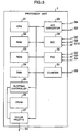
- Fig. 5 is a hardware structural view of an arithmetic processing portion of the embodiment of the present invention;
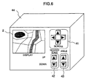
- Fig. 6 is an explanatory view showing appearance of a navigation apparatus according to an embodiment of the present invention;
- Fig. 7 is a functional structural view of an arithmetic processing portion for accomplishing bird's-eye view map display;
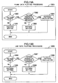
- Fig. 8 is a flowchart of map plotting means for accomplishing bird's-eye view map display;
- Fig. 9 is a flowchart of coordinates conversion means for accomplishing bird's-eye view map display;
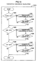
- Fig. 10 is a flowchart of perspective conversion computation for accomplishing bird's-eye view map display;
- Fig. 11 is a flowchart of display position computation for accomplishing bird's-eye view map display;
- Fig. 12 is a flowchart of plotting judgement means for accomplishing bird's-eye view map display;
- Figs. 13A and 13B are flowcharts of polygonal and linear pattern displays in bird's-eye view map display;
- Fig. 14 is a flowchart of character string display in bird's-eye view map display;
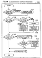
- Fig. 15 is a flowchart of character plotting means;
- Figs. 16A, 16B, 16C and 16D show an embodiment for character fringing display for representing one character by a plurality of characters;
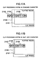
- Figs. 17A and 17B show an embodiment for character clipping processing;
- Figs. 18A to 18J show an embodiment for display means of a fringed character;
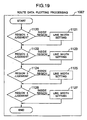
- Fig. 19 is a flowchart of a route display in bird's-eye view map display;
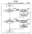
- Fig. 20 is a flowchart of orbit display in bird's-eye view map display;
- Fig. 21 is a flowchart of artificial background display in bird's-eye view map display;
- Fig. 22 is a flowchart of mark display in bird's-eye view map display;
- Figs. 23A, 23B and 23C are explanatory views useful for explaining a setting method of a visual point and a projection plane in bird's-eye view map display;
- Figs. 24A, 24B and 24C are explanatory views useful for explaining a setting method of a visual point and a projection plane in bird's-eye view map display;
- Figs. 25A and 25B show an embodiment for optimization display of the present position in bird's-eye view map display;
- Figs. 26A, 26B, 27A, 27B, 28A, 28B, 29A and 29B show an embodiment for character string overlap judgement in bird's-eye view map display;
- Figs. 30A, 30B, 31A, 31B, 32A, 32B, 33A and 33B show an embodiment for character string overlap judgement in bird's-eye view map display;
- Figs. 34A, 34B, 35A, 35B, 36A, 36B, 37A and 37B show an embodiment for character string overlap judgement in bird's-eye view map display;
- Figs. 38A, 38B and 38C show an embodiment for avoiding character string overlap display in bird's-eye view map display;
- Figs. 39A and 39B show an embodiment for avoiding character string overlap display in bird's-eye view map display;
- Figs. 40A, 40B and 40C show an embodiment for displaying the same character string in bird's-eye view map display;
- Figs. 41A, 41B and 41C show an embodiment for polygonal and linear pattern display in bird's-eye view map display;
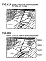
- Figs. 42A and 42B show an embodiment for route display in bird's-eye view map display;
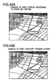
- Figs. 43A and 43B show an embodiment for orbit display in bird's-eye view map display;
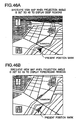
- Figs. 44A and 44B show an embodiment for artificial background display in bird's-eye view map display;
- Figs. 45A and 45B show an embodiment for mark display in bird's-eye view map display; and
- Figs. 46A and 46B show an embodiment for present position mark display in bird's-eye view map display.
- Fig. 1 shows an example of the bird's-eye view map displayed by a bird's-eye view map display device mounted to a navigation system according to an embodiment of the invention. The bird's-eye view map display device according to this embodiment generates a bird's-
eye view 102 showing a bird's-eye view from a specific position as a projection chart of two-dimensional map data (indicated byreference numeral 101 in Fig. 1), and displays it on a display screen of adisplay 2. Incidentally, in the bird's-eye view 102 shown in Fig. 1, a foldedline 103 is provided with a thick line and is highlighted in order to represent a guiding route. Anartificial background 104 represents the sky, amark 105 represents the present position and anorbit mark 106 represents the orbit of a car so far driven. Further, arrows in Fig. 1 represent the relationship of projection from the two-dimensional map data 101 to the bird's-eye view 102. - - The outline of bird's-eye view map display as the characterizing feature of the present invention will be explained with reference to Fig. 2.
- In printed map charts or in the navigation systems according to the prior art, a map is represented by a plan map display obtained when a given area is viewed from an infinitely remote point above this area. Because this plan map display has the advantage that a reduced scale is constant irrespective of points inside the same display screen, the feel of distance is easy to grasp. When an area between certain two points is represented on the same screen, however, the operation for adjusting and optimizing the reduced scale of the map display becomes necessary, and if the distance between these two points is great, only limited information can be displayed because the quantity of information that can be displayed at one time is restricted by the size of the display used and the level of its precision. Bird's-eye view display is employed as means for solving this problem. When this bird's-eye view display is used, the information of those portions which are close to the visual point is enlarged while the information of those remote from the visual point is reduced, as is obvious from Fig. 2. Therefore, when the area between certain two points is displayed on the same screen, the point for which more detailed information is required is situated close to the visual point with the other being remote from the visual point, and their mutual positional relationship is represented in an easily comprehensible form by displaying the two points on the same screen. Further, a greater quantity of information can be provided to the user on the information near the visual point. This bird's-eye view display can be accomplished by effecting perspective conversion which projects two-or three-dimensional map information of a plane A to a plane B describing a certain angle e with the plane A. Since two-dimensional map data can be used as the map information used, bird's-eye view display is feasible by adding the perspective conversion function to existing navigation systems without adding new map data, but various contrivances must be made when the bird's-eye view display is put into practical use.
- Fig. 4 shows a structural example of a navigation apparatus for a mobile body to which the present invention is applied.
- Hereinafter, each structural unit of this navigation apparatus will be explained. A
processor unit 1 detects the present position on the basis of the information outputted from various sensors 6 to 9, reads the map information necessary for display from amap memory unit 3 on the basis of the present position information so detected, graphically expands the map data, displays this data on adisplay 2 by superposing a present position mark, selects an optimum route connecting the destination indicated by the user to the present position and guides the user by using a speech input/output device 4 or thedisplay 2. In other words, it is a central unit for executing various processings. Thedisplay 2 is the unit which displays the graphic information generated by theprocessor unit 1, and comprises a CRT (Cathode-Ray Tube) or a liquid crystal display. A signal S1 between the processor unit and the display is generally connected by RBG signals or NTSC (National Television System Committee) signals. Themap memory device 3 comprises a large capacity memory medium such as a CD-ROM or an IC card and executes read/write processing of the required map data. The speech input/output device 4 converts the message to the user generated by theprocessor unit 1 to the speech signals, outputs them, recognizes the user's voice and transfers it to theprocessing unit 1. Aninput device 5 is the unit that accepts the user's instruction, and comprises hard switches such asscroll keys 41, reducedscale keys 42 andangle changing keys 43 shown in Fig. 6, for example, a joystick, touch panels bonded on the display, or the like. The sensor used for detecting the position in the navigation system for a mobile body comprises a wheel speed sensor 6 for measuring the distance from the product of the circumference of a wheel and the number of revolution of the wheel and measuring a turning angle of the mobile body from the difference of the numbers of revolution of the wheels forming a pair, a terrestrial magnetic sensor 7 for detecting the magnetic field of the earth and detecting the moving direction of the mobile body, agyro sensor 8 for detecting the turning angle of the mobile body such as an optical fiber gyro or an oscillation gyro, and a GPS receiver 9 for receiving signals from a GPS satellite, measuring the distance between the mobile body and the GPS satellite and the change ratio of this distance for at least three satellites and thus measuring the present position of the mobile body, its travelling direction and its course. Theinput device 5 further includes atraffic information receiver 10 for receiving signals from beacon transmitters that transmit traffic information such as road jamming information, closed-to-traffic information, parking lot information, etc., and from FM multiplex broadcasting. Furthermore, aninternal LAN device 11 is provided so as to receive various information of the car such as door open/close information, the information on the kind and condition of lamps turned ON, the information of the engine condition, the information on the result of trouble-shooting, and so forth. - Fig. 5 is an explanatory view showing the hardware construction of the processor unit.
- Hereinafter, each constituent element will be explained. The
processor unit 1 employs the construction wherein devices are connected by a bus. The devices include aCPU 21 for executing computation of numerical values and controlling each device, anRAM 22 for storing the map and the operation data, anROM 23 for storing the program and the data, a DMA (Direct Memory Access) 24 for executing data transfer at a high speed between the memory and the memory and between the memory and each device, a plottingcontroller 25 for executing at a high speed graphic plotting such as expansion of vector data to pixel information, etc., and for executing display control, aVRAM 26 for storing graphic image data, acolor palette 27 for converting the image data to the RGB signals, an A/D convertor 28 for converting analog signals to digital signals, anSCI 29 for converting serial signals to parallel signals in synchronism with the bus, aPIO 30 for establishing synchronism with the parallel signal and putting it on the bus, and acounter 31 for integrating pulse signals. - Fig. 7 is a explanatory view useful for explaining the functional construction of the
processor unit 1. - Hereinafter, each constituent element will be explained. Present position calculation means 66 integrates on the time axis the distance data and the angle data obtained by integrating the distance pulse data S5 measured by the wheel speed sensor 6 and the angular velocity data S7 measured by the
gyro 8, respectively, and calculates the position (X', Y') after driving of the mobile body from the initial position (X, Y). In order to bring the rotating angle of the mobile body into conformity with the azimuth of driving, the azimuth data S6 obtained from the terrestrial magnetic sensor 7 and the angle data obtained by integrating the angular velocity data from thegyro 8 are mapped on the 1:1 basis, and the absolute azimuth of the driving direction of the mobile body is corrected. When the data obtained from the sensors described above are integrated on the time axis, the sensor errors accumulate. Therefore, a processing for canceling the errors so accumulated is executed in a certain time interval on the basis of the position data S8 obtained from the GPS receiver 9, and the present position information is outputted. Since the present position information acquired in this way contains the sensor errors, map-match processing 67 is executed so as to further improve positional accuracy. This is the processing which collates the road data contained in the map in the proximity of the present position read by the data read processing means 68 with the driving orbit obtained from the present position calculation means 66, and brings the present position to the road having the highest similarity of shape. When this map-match processing is executed, the present position coincides in most cases with the driving road, and the present position information can be accurately outputted. The present position information calculated in this way is stored in orbit memory means 69 whenever the mobile body drives in a predetermined distance. The orbit data is used for plotting an orbit mark on the road on the corresponding map for the road through which the mobile body has run so far. - On the other hand, user operation analysis means 61 accepts the request from the user by the
input device 5, analyzes the content of the request and controls each unit so that a processing corresponding to the request can be executed. When the user requests to guide the route to the destination, for example, it requires the map plotting means 65 to execute processing for displaying the map for setting the destination and further requests route calculation means 62 to execute processing for calculating the route from the present position to the destination. The route calculation means 62 retrieves a node connecting between two designated points from the map data by a Dichistler method, etc., and stores the route so obtained in route memory means 63. At this time, it is possible to determine the route in which the distance between the two points is the shortest, the route through which the destination can be reached within the shortest time or the route through which the driving cost is the lowest. Route guiding means 64 compares the link information of the guide route stored in the route memory means 63 with the present position information obtained by the present position calculation means 66 and the map match processing means 67 and notifies to the user whether or not to drive straight or whether or not to turn right or left before passing by a crossing, etc., by the speech input/output device 4, displays the travelling direction on the map displayed on the display, and teaches the route to the user. Data read processing means 68 so operates as to prepare for reading the map data of the requested region from themap memory device 3. Map plotting means 65 receives the map data around the point for which display is requested from the data read processing means 68 and transfers the command for plotting the designated object in the reduced scale, the plotting direction and the plotting system that are designated, respectively, to graphic plotting means 71. On the other hand, menu plotting means 70 receives a command outputted from the user operation analysis means 61 and transfers a command for plotting various kinds of requested menus and marks to be displayed in overlap with the map to graphic processing means 71. The graphic processing means 71 receives the plotting commands generated by the map plotting means 65 and the menu plotting means 70, and expands the image on theVRAM 26. - Fig. 8 is an explanatory view useful for explaining the functions of the map plotting means 65.
- Hereinafter, each constituent element will be explained. Display region judgement means 81 decides the display reduced scale of the map and decides also which region should be displayed with which point of the map data as the center. Initial data clip means 82 selects, by clip processing, the data necessary for display from the line data, the plan data and the character data representing objects such as roads, buildings, etc., necessary for subsequent processings from each mesh of the map data read out by the data read processing means 68 from the
map memory device 3, the line data comprising recommended routes and stored in the route memory means 63 and the point data comprising driving orbits and stored in the orbit memory means 69, on the basis of the information set by the display region judgement means 81. The clip processing algorithms hereby used include a Cohen-Sutherland line clip algorithm for the line and point data and a Sutherland-Hogman polygon clip algorithm for the plan and character data (Foley, van dam, Feiner, Hughes: Computer Graphics: Addison-Wesley Publishing Company, pp. 111-127). This processing can reduce the data quantity which should be subsequently subjected to coordinates conversion and plotting processing and can improve a processing speed. - Coordinates conversion means 83 enlarges or reduces the map data obtained by the clip processing to the target size and when an object must be displayed by rotating it, this means 83 so functions as to effect affin conversion of each coordinates value of the map data. Plotting judgement means 84 so functions as to select those data which are practically necessary for plotting by using the map data obtained by the coordinates conversion means 83. When the reduced scale is great, for example, the data quantity to be plotted substantially increases. Therefore, this means 84 so functions as to omit small roads and the names of places which may be omitted, and to eliminate character strings that are displayed in superposition with one another. Data clip means 85 so functions as to select the map data relating to the plotting area from the map data obtained from the plotting judgement means 84, by clip processing. The clip processing algorithm hereby used may be the same algorithm used by the initial data clip means. Further, this processing may be omitted. Artificial background setting means 86 provides the function which is necessary for bird's-eye view map display and displays the artificial background such as the horizontal line, the sky, etc., in order to reduce the plotting data quantity and to improve the screen recognition property. Plotting command generation means 87 generates commands for plotting lines, polygons, characters, etc., so as to plot the resulting point, line and plane data as well as the character data by the designated colors and patterns, and the command for setting the colors and the patterns and outputs them to the graphic processing means 71.
- Next, the fundamental display system of the bird's-eye view map display will be explained with reference to Figs. 3A, B, C, D and Fig. 8.
- At first, the region for bird's-eye view display is decided by the display region judgement means 81 from the position of the visual point and the direction of the visual field and from the angle e (projection angle) described between the plane A and the plane B in Fig. 2 (
step 1 in Fig. 3A). When a bird's-eye view is displayed on a rectangular display, map data of a narrow region is necessary for the area near the visual point and map data of a broad region is necessary for the area remote from the visual point. Therefore, the map data of a trapezoidal mesh regions in the drawings is plotted finally. Next, the necessary map data is extracted by the initial data clip means 82 from the map mesh data inclusive of the region for bird's-eye view display by using the rectangular regions which are circumscribed with the trapezoidal region to be practically plotted (step 2 in Fig. 3B). Next, the coordinates conversion means 83 enlarges or reduces the extracted data and then executes affin conversion so that the trapezoid stands upright. Further, perspective conversion is executed so as to convert each coordinates value of the map data to the data which is represented three-dimensionally (step 3 in Fig. 3C). In this instance, perspective conversion is expressed by the following equations (1) and (2) where the position coordinates of the visual point are (Tx, Ty, Tz), the angle between the plane A and the plane B is e, the map data coordinates values before conversion are (x, y) and the map data coordinates values after conversion are (x', y'):

- The trapezoid represented at the
step 2 in Fig. 3B is subjected to coordinates conversion into the rectangular region represented at thestep 3 in Fig. 3C whereas the rectangle circumscribed with the trapezoid represented at thestep 2 in Fig. 3B is subjected to coordinates conversion into a deformed rectangle circumscribed with the rectangle represented at thestep 3 in Fig. 3C, by perspective conversion, respectively. Because the portions other than the rectangular region need not be plotted, these portions other than the rectangular region are clipped by the data clip means 85 (step 4 in Fig. 3D). The plotting command generation means 87 generates the plotting command by using the map data so obtained, and the graphic processing means 71 conducts plotting to theVRAM 26 so that the bird's-eye view map shown in Fig. 1 can be displayed. - Next, the perspective conversion parameters in bird's-eye view map display, that is, the angle e between the map and the projection plane (projection angle) and the coordinates (Tx, Ty, Tz) of the origin of the visual point coordinates system containing the projection plane, which is viewed from the object coordinates system containing in turn the map plane, or in other words, the method of calculating the position of the projection plane, will be explained with reference to Figs. 23A, B and C. It is desired for the navigation apparatus to display in detail the point at which the user is now driving, that is, the region around the present position. Therefore, the explanation will be given on the case where the present position is displayed at the lower center portion of the screen as shown in Fig. 23C. To accomplish bird's-eye view display, it is judged whether rotation of map is necessary at
step 1002, and in the event the rotation is considered necessary then the angle φ between the driving direction vector and the base of the map mesh is first determined at thestep 1004 in Fig. 9, and affin conversion for rotating the map data to be plotted by the angle φ is executed for each data constituting the map (step 1005). Since bird's-eye view display is judged as being made at thestep 1006, the flow proceeds to the processing for calculating the projection angle e and the position of the visual point (steps 1008 and 1009). The projection angle e is set to an angle near 0 when it is desired to make display so that the difference of the reduced scale becomes small between the portions near the visual point and the portions away from the visual point, and is set to near 90° when it is desired to make display so that the difference of the reduced scale becomes great between the portions near the visual point and the portions away from the visual point. Normally, the projection angle e is set to the range of about 30 to about 45°. Since the user desires to arbitrarily set the map region to be displayed by bird's-eye view map display, the projection angle e can be set by the projectionangle change key 43 provided to the navigation apparatus shown in Fig. 6. When this key 43 is so operated as to increase the projection angle, the projection angle increases, so that the map of remote regions is displayed. When the key 43 is so operated as to decrease the projection angle, the projection angle e decreases, so that the map near the present position is displayed. - Next, as to the position (Tx, Ty, Tz) of the projection plane, calculation is executed at the
step 1009 so that the difference Δx, Δy, Δz) obtained by subtracting the position (Tx, Ty, Tz) of the position of the projection plane from the present position (x, y, z) is always a constant value. As the absolute values, further, Δx is set to 0, Δz is set to a small value when display is made by a small reduced scale in match with the reduced scale of the map display and to a large reduced scale when display is made by a large reduced scale. Normally, Δz is decided preferably so that the reduced scale of the plane view is coincident with the reduced scale of a certain point near the center of bird's-eye view display. Since the reduced scale of the map is preferably changeable in accordance with the user's request, thestep 1009 operates in such a manner as to set Δz to a small value when the user designates a small reduced scale by the reduced scale key 42 provided to the navigation apparatus shown in Fig. 6 and to a large value when a large reduced scale is designated. The Δy value may be either a positive value or a negative value but this embodiment uses the negative value and sets it so that the present position is displayed at a lower 1/3 position of the screen.Step 1010 executes perspective conversion of each coordinates value of the map data by using the projection angle e and the position (Tx, Ty, Tz) of the projection plane that are obtained in the manner described above. - The detail of this perspective conversion operation will be explained with reference to Fig. 10. First, whether or not the plane data constituted by polygons such as water systems, green zones, etc., exist is judged (step 1020). When the result proves YES, perspective conversion is executed for each node constituting the polygon (step 1021). This operation is executed for all the polygons (step 1022). Next, when the line data constituting the map such as the roads, the railways, the administrative districts, etc., and the optimum route from the present position to the destination are calculated, whether or not the line data representing the route exist is judged (step 1023). When the result proves YES, perspective conversion is executed for each node that constitutes the line (step 1024). Further, when the character data constituting the map such as the area names, symbols, etc., and the orbit are displayed, whether or not the point data representing the orbit exist is judged (step 1026). As to the character strings such as the area names, symbols, etc., it is advisable to handle one point representing a given character string such as the upper left end point of the character string as the point data. When these point data are judged as existing, perspective conversion is executed for each node constituting the point (step 1027) and is then executed for all the points (step 1028). The graphic processing means 71 executes plotting processing by using the map data so obtained. In consequence, in bird's-eye view map display shown in Fig. 23C, the driving direction is always displayed in the UP direction on the screen and the present position is always displayed at the same point on the screen.
- Next, the explanation will be given on the display method of the bird's-eye view map, which can be easily recognized by the driver, when a certain destination is designated by the
input device 5 from the map or the retrieved screen, will be explained with reference to Fig. 9 and Figs. 24A, B and C. It is desired for the navigation apparatus to display in detail the point at which the user is driving at present, that is, the area near the present position. Therefore, the present position is displayed at the center lower portion of the screen, more concretely at the lower 1/3 region of the transverse center of the screen, as shown in Fig. 24C. To accomplish bird's-eye view display shown in Fig. 24C, the angle φ between the line perpendicular to the line connecting the present position to the destination shown in Fig. 24A and the base of the map mesh is first determined at thestep 1004 in Fig. 9 and affin conversion is executed by the angle φ for each coordinates value of the map data to be plotted (step 1005). Since this bird's-eye view display is judged as being made at thestep 1006, the flow then proceeds to the processings for calculating the projection angle e and the position of the visual point (steps 1008 and 1009). The projection angle e is set to an angle near 0 when it is desired to make display so that the difference of the reduced scale between small between the portions near the visual point and the portions away from the visual point, and is set to an angle near 90° when it is desired to make display so that the difference of the reduced scale becomes great between the portions near the visual point and the portions away from the visual point. Normally, the projection angle is set to the range of about 30 to about 45°. Since the user desires to arbitrarily set the map region to be displayed by bird's-eye view map display, the projection angle e can be set by the projectionangle change key 43 provided to the navigation apparatus shown in Fig. 6. When this key 43 is so operated as to increase the angle, the projection angle e increases, so that the map of remote portions is displayed. When the key 43 is so operated as to decrease the projection angle, the projection angle e decreases, so that the map near the present position is displayed. - Next, as to the position (Tx, Ty, Tz) of the projection plane, calculation is made at the
step 1009 so that the difference (Δx, Δy, Δz) obtained by subtracting the position (Tx, Ty, Tz) of the projection plane from the present position (x, y, z) becomes always a constant value. As the absolute values, Δx is set to 0, and Δz is set to a small value when display is made by a small reduced scale in match with the reduced scale of the map displayed, and to a great value when display is made by a large reduced scale. Normally, Δz is preferably set so that the reduced scale of the plan view is coincident with the reduced scale of a certain point near the center of bird's-eye view display. Since the desires to change the reduced scale of the map, thestep 1009 so operates as to set a small value to Δz when the user designates a small reduced scale by the reduced scale key 42 provided to the navigation apparatus shown in Fig. 6 and to set a large value to Δz when the user designates a large reduced scale. The Δy value may be either a positive value or a negative value, but this embodiment uses the negative value and determines the value so that the present position can be displayed at the lower 1/3 position of the screen. Thestep 1010 executes perspective conversion of each coordinates value of the map data by using the projection angle e and the position (Tx, Ty, Tz) of the projection plane so obtained, and the graphic processing means 71 executes the plotting processing by using the resulting map data. Consequently, in bird's-eye view display shown in Fig. 24C, the destination is always displayed in the UP direction and the present position is always displayed at the same position on the screen. The navigation apparatus becomes easier to operate by switching the operation mode to the mode in which the destination and the present position are fixed always at certain two points on the screen when the car moves to the position where the destination can be displayed on the screen. - Incidentally, the polygon representing the Imperial Palace, the green zones and the water systems such as sea and lakes are not much useful as the information for the driver driving the car having the navigation apparatus, as shown in Fig. 24A. Rather, a greater quantity of information which is directly necessary for driving, such as the road information, are displayed preferably on the limited screen. Means for solving this problem will be explained with reference to Fig. 11. The information of the roads and the background are represented by the nodes, and the node density of the polygons representing the green zones and the water systems such as sea and lakes tends to be lower than the node density of the lines such as the roads. Therefore, the greatest quantity of information of the roads, etc., are displayed by optimizing the display region in the transverse direction of the screen, for the region displayed in the longitudinal direction, in accordance with the initial value. This processing is executed by the display position calculation routine at the
step 1011 in Fig. 9. First, whether the mode is for executing optimization of the display position is judged (step 1040). When optimization is judged as to be executed, the nodes that are practically displayed on the screen are extracted from the nodes constituting the lines and the polygons subjected to perspective conversion at thestep 1041 by clip calculation (step 1041). Further, the difference Δx between the x coordinates arithmetic mean value obtained at thestep 1042 and the x-coordinates value x2 at the center of the screen is calculated (step 1043). At thenext step 1044, the difference Δx obtained by thestep 1043 is added to the x-coordinates value of the nodes constituting the line and the polygon. The graphic processing means 71 executes the plotting processing by using the map data obtained in this manner. In consequence, bird's-eye view map display capable of displaying a greater quantity of those information which are directly necessary for driving, such as the roads, can be displayed on the screen as shown in Fig. 25B. - Next, the method of the plotting processing of the objects constituting the bird's-eye view map will be explained more concretely. The plotting judgement means 84 shown in Fig. 12 operates in such a manner as to optimally display the plan data, the line data and the character data constituting the map, the route data calculated in accordance with the request from the user and the orbit data representing the route so far driven, respectively.
- First, whether or not the plane data exists in the plotting data is judged (step 1060). When the plane data is judged as existing, the flow proceeds to the plane data plotting processing (step 1061) shown in Fig. 13A. The plane data plotting processing judges whether the plane pattern exists inside the polygon to be practically plotted or whether the full plane should be smeared away (step 1080). When the plane pattern is not judged as existing, pattern setting is so effected as to smear away the entire portion inside the polygon and the processing is completed (step 1081). When the plane pattern is judged as existing, whether or not perspective conversion is to be executed for the plane pattern is judged (step 1082). When the plane pattern is subjected to perspective conversion and is displayed, the pattern has the feel of depth as depicted in Fig. 41A and can be therefore displayed more three-dimensionally. However, the plotting time gets elongated because the processing quantity becomes greater. When the plane pattern used for plan view map display is displayed, on the other hand, the display becomes planar as depicted in Fig. 41B, but the processing can be made at a higher speed because the plane pattern can be handled two-dimensionally. Therefore, when a higher processing speed is required, perspective conversion of the pattern is judged as unnecessary at the
step 1082 and the designated pattern itself is set as the pattern data (step 1083). When display quality has higher priority, on the other hand, perspective conversion of the pattern is judged as necessary at thestep 1082. Therefore, the pattern is subjected to perspective conversion and the conversion result is set as the pattern data (step 1084). The method shown in Fig. 41C may be employed as means for improving this processing speed. This method divides a polygon into a plurality of regions (four regions shown in the drawing) in the direction of depth and smearing away each region by using the mean pattern obtained by subjecting the plane pattern to perspective conversion in each of the region. Since the pattern becomes a two-dimensional pattern inside the region according to this method, the processing speed can be improved. - Next, whether or not the line data exists in the plotting data is judged (step 1062). When the line data is judged as existing, the processing shifts to the line data plotting processing (step 1063) in Fig. 13B. In this line data plotting processing, whether the line pattern exists in the lines practically plotted or is smeared by solid lines is judged (step 1085). When the line pattern is not judged as existing, pattern setting is effected so as to draw the solid lines and the processing is completed (step 1087). When the line pattern is judged as existing, whether or not perspective conversion is to be effected for the line pattern is judged (step 1087). When the line pattern is subjected to perspective conversion and is displayed, the feel of depth develops as shown in Fig. 41A and representation can be made more three-dimensionally. However, the plotting time gets elongated in this case because the processing quantity increases. When display is made by the line pattern used for plan view map display, display becomes planar as shown in Fig. 41B, but high speed processing can be made because the line pattern can be handled unidimensionally. Therefore, when a higher processing speed is required, perspective conversion of the pattern is not judged as necessary at the
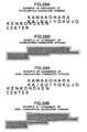
step 1087 and the designated pattern itself is set as the pattern data (step 1088). On the other hand, when higher priority is put to display quality, perspective conversion of the pattern is judged as necessary at thestep 1087. Therefore, the pattern is subjected to perspective conversion and the converted result is set as the pattern data (step 1089). - Next, whether or not the character data exists in the plotting data is judged (step 1064). When the character data is judged as existing, the processing proceeds to the character data plotting processing (step 1065) in Fig. 14. The character data plotting processing judges to which attribute the character string in the map, which character string comprises a plurality of attributes such as the names of places, the names of buildings, the map symbols, etc., belong (step 1100), selects the character strings having predetermined attributes that must be displayed essentially, and hands over the processing to the
step 1101. Since the character string having the attributes that must be essentially displayed is selected, buffering is made so as to display this character string at thestep 1101. Next, overlap of one character string with another is judged (step 1102). There are a plurality of methods for judging overlap of the character strings. The first method calculates the polygon encompassing the character string (the outer frame of the polygon shown in Figs. 26A and B) as shown in Figs. 26A, B, 27A, B, 28A, B, 29A and B and judges the overlap of the characters by using a polygonal region information (the hatched pattern region of the polygon shown in Figs. 27A and B) constituted positioned inward by a predetermined number of bits from the polygon. According to this method, the character strings are judged as overlapping when the overlap judgement regions (the hatched pattern regions of the polygons) overlap with one another as shown in Figs. 28A and B. When the character overlap judgement regions do not overlap as shown in Figs. 29A and B, the character strings are not judged as overlapping. Generally, the respective character strings can be discriminated even when the characters overlap to some extents, and this system operates in such a manner that overlap of the character strings to some extents are not judged as overlapping. Accordingly, the overlapping character strings are not omitted more than necessary, and the quantity of information to be transmitted to the driver increases. - Next, the second method will be explained with reference to Figs. 30A, B, 31A, B, 32A, B, 33A and B. This method calculates the rectangular regions circumscribed with the character string (the rectangles shown in Figs. 30A and B) and judges overlap of the character strings by using the rectangular region information (the hatched rectangular regions shown in Figs. 30A and B). According to this method, when the overlap judgement regions of the character strings (the hatched rectangular regions) overlap with one another as shown in Figs. 32A and B, the character strings are judged as overlapping. When the character overlap judgement regions do not overlap with one another as shown in Figs. 33A and B, the character strings are not judged as overlapping. Since this method can judge overlap of a plurality of character strings by a simple shape of the rectangle, the minimum and maximum values of the rectangle in the x- and y-axis directions may be merely compared between the overlapping character strings, and the operation time can be therefore shortened.
- Finally, the third method will be explained with reference to Figs. 34A, B, 35A, B, 36A, B, 37A and B. This method calculates the rectangular region circumscribed with the character string (the rectangle of the outer frame shown in Figs. 35A and B) and judges overlap of the character strings by using the rectangular region information (the hatched rectangular pattern region shown in Figs. 35A and B) constituted by a region positioned inward by a predetermined number of dots from the rectangle. According to this method, the character strings are judged as overlapping when the overlap judgement regions of the character strings (the hatched rectangular pattern regions) overlap with one another as shown in Figs. 36A and B. The character strings are not judged as overlapping when the overlap judgement regions do not overlap with one another as shown in Figs. 37A and B. Generally, the respective character strings can be discriminated even when overlap of characters occurs to some extents, and this system operates in such a manner that the character strings are not judged as overlapping even when they overlap to some extents. Therefore, the overlapping character strings are not omitted more than necessary, and the quantity of the information to be transmitted to the driver increases. Further, because overlap of a plurality of character strings is judged by a simple shape of the rectangle, the minimum and maximum values in the x- and y-axis directions may be merely compared between a plurality of character strings, and the operation time can be shortened.
- When overlap of the character strings is judged as existing after overlap is judged by any of the three kinds of character overlap judgement means described above, the attributes of the overlapping character strings are examined (step 1103). When the attributes of the overlapping character strings are judged as different, the character strings having the attributes which are decided as having higher priority for display are selected and are buffered (step 1104). Such an embodiment is shown in Figs. 38A, B and C. It will be hereby assumed that the initial state has the screen structure such as shown in Fig. 38B, and comprises the symbol attributes constituted by symbols such as double circles and the post marks, and the character string attributes constituted by the character strings. If the symbol attributes are to be preferentially displayed when the processing of the
step 1104 is executed, the symbol attributes are preferentially displayed when the character string and the symbol overlap with each other as shown in Fig. 38A. In other words, the position at which "double circle" and the place name "Marunouchi" overlap with each other is displayed by the "double circle" and at the position at which the postal symbol "T" overlaps with the place name "Kandabashi" is displayed by the symbol " T ". Next, when the attributes of the character strings are judged as the same as a result of examination of the attributes of the overlapping character strings (step 1103), sorting is then effected in the depth-wise direction for the character string (step 1105). Further, the character string close to the present position is selected and is then buffered (step 1106). Such an embodiment is shown in Fig. 38C. Here, if the character strings overlap with each other when the processing of thestep 1106 is executed, the character string closer to the present position is displayed. In other words, when the name "Tokyo" and the name "Marunouchi 2" overlap, "Tokyo" is displayed, and when the name "Hitotsubashi" and "Ohtemachi" overlap, "Ohtemachi" is displayed. The explanation given above deals with the method of selecting and displaying the character strings when display of the character strings overlap, but there is still another method which replaces display of the overlapping character strings by small fonts and displays them as shown in Figs. 39A and B. In other words, when overlap of the character strings is judged as existing at thestep 1102 in Fig. 14, these character strings are displayed in the font size smaller than the designated font size. If the designated font size of characters is 24x24 pixels, for example, display is made in the font size of 16x16 pixels or 12x12 pixels. Since overlap of the character strings becomes smaller as shown in Fig. 39B in this case, recognition performance of the character strings can be improved. Next, whether or not the same character string, which expresses the same characters in the same sequence, exists in the character strings is judged (step 1107). When the same character string is judged as existing, the distance between the character strings is then calculated (step 1108). Here, the term "distance between the character strings" represents the difference of the position data of the characters put on the map data or the difference of the position data of the characters when the character strings are displayed on the bird's-eye view map. To calculate the distance, it is advisable to use one point representing the character string, that is, the upper left end point or the central point of the character string. Whether or not the distance between the character strings so calculated falls within a predetermined area is judged (step 1109) and when the result proves YES, the character strings in the proximity of the present position are buffered (step 1110). The operation example will be explained with reference to Figs. 40A, B and C. Under the initial state shown in Fig. 40A, four character strings representing an interchange exist. The distances between these character strings are calculated as shown in Fig. 40B, and the character strings in the proximity of the present position, which has small distances, are selected, while both character strings are selected for those having large distances. In consequence, the character strings are displayed as shown in Fig. 40C. As can be clearly understood from these drawings, the character strings which are not necessary as the information are omitted and only the character strings which are absolutely necessary are left. Therefore, the driver can more easily recognize them. - Next, the character plotting means 1185, which can be inserted as a sub-routine to the final step of the flowchart shown in Fig. 14, will be explained concretely with reference to Fig. 15.
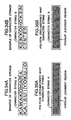
- Here, whether or not decorated characters, or the like, are designated as a character style is first judged (step 1201). The decorated characters include bold-faced characters having a thick character line so as to highlighten the characters and fringed characters having a background color or a frame of a designated specific color around the lines constituting a given character in order to have the character more comprehensible when it is displayed in superposition in a region where a large number of lines and planes are displayed as the background. Reference numeral 2181 in Fig. 18A represents an example of such a fringed character. This fringed character can be plotted in the following way. First, character plotting is effected for a character to be fringed at a position of one dot 2182 (Fig. 18B) from the upper left of the coordinates in which the object character is to be plotted, in the background color. Further, character plotting is effected eight times, in total, in the same way by using the background color at an upward position by one dot 2183 (Fig. 18C), at a right upward position by one dot 2184 (Fig. 18D), at a left position by one dot 2185 (Fig. 18E), at a right position by one dot 2186 (Fig. 18F), at a left downward position by one dot 2187 (Fig. 18G), at a downward position by one dot 2188 (Fig. 18H) and at a right downward position by one dot 2189 (Fig. 18I), respectively. Finally, the intended character is plotted at the designated coordinates position in the designated color (2191 in Fig. 18J). As a modified example of the fringed characters, there is a method which displays the background color in the predetermined directions of the character, for example, to the right, down and right downward, or a frame having a designated specific color.
- When the character is not judged as the decorated character in the character style judgement, the relation between the designated character and the clip region is judged by clip judgement (step 1207) so as to call the character plotting routine having, or not having, the clip in the pixel unit. The clip processing routine compares the character plotting start coordinates, for example, the left lower end point of the designated character, with the clip region and judges whether or not the left lower end point of this character is contained in the
clip region 2162, the plottingregion 2161 or other regions, as shown in Figs. 17A and B. By the way, when the character to be plotted is the standard character, the clip region is expanded to the left by the width of the character and in the down direction by the height of the character from the plotting region. Assuming that the height of the standard character and the half-size character is h, the width of the standard character is w, the width of the half-size character is w', the left lower end point of the plotting region is (x1, y1) and the right upper end point is (x2, y2), for example, the left lower end point of the clip region in the standard character is (x1-w, y1-h), its right upper end point is (x2, y2), the left lower end point of the clip region in the half-size character is (x1-2', y1-h) and its right upper end point is (x2, y2). The left lower end points of the characters indicated byreference numerals reference numerals reference numerals - When the character is judged as having decoration in the
character style judgement 1201, whether or not the designated character constitutes on character by a plurality of characters is judged (step 1202). As an example of one character string constituted by a plurality of characters, there is a character of the shape having a size which exceeds the size that can be expressed by one character as shown in Fig. 16A. When decoration is applied in a character unit to such a character string, afringe 2143 is displayed at the boundary of arespective character 2142 in the case of a fringed character, for example, as shown in Fig. 16B, and display quality drops. Therefore, when a plurality of characters are judged as constituting one character string, the flow jumps to the routine which does not put decoration to the characters. Incidentally, there is a method which examines the character codes and judges that a plurality of characters constitute one character string when the codes are within a predetermined region, as a method of judging that a plurality of characters constitute one character string. Accordingly, in the case of the decorated characters such as the fringed characters, too, thefringe 2143 is not displayed at the boundary of eachcharacter 2142 and display quality can be improved. The operations after theclip judgement 1207 are the same as in the foregoing explanation. - Next, when a plurality of characters are not judged as constituting one character string at the
step 1202, whether or not the designated character is displayed in superposition with other characters is judged (step 1203). Here, whether or not the designated character overlaps with a plurality of characters that constitute one character is evaluated. The decorated characters such as the fringe characters intend to display more comprehensively those characters which overlap with the background information such as the lines and planes. When the decorated character such as the fringed character is displayed when overlapping characters exist, the overlapping character string becomes difficult to discriminate. There is also the case where one symbol, or the like, is displayed by combining the character constituting one character by a plurality of characters with character to be displayed in superposition with the former, and in such an application, the characters to be displayed in superposition need not be the decorated characters. Therefore, whether or not the designated character is displayed in superposition with other characters is examined at thestep 1203, and when it is, the flow jumps to the routine which does not put decoration to the character. In consequence, display such as shown in Fig. 16D is executed, and intended display can be accomplished. The operations after theclip judgement 1207 is the same as in the foregoing embodiment. - Next, when the designated character is not judged as being displayed in superposition with other characters at the
step 1203, plotting of the decorated characters is executed. The relation between the designated character and the clip region is judged by the clip judgement (step 1204) and the character plotting routine having, or not having, the clip in the pixel unit is called. The clip processing routine compares the plotting start coordinates of the character such as the left lower end point of the designated character with the clip region, and judges whether or not the left lower end point of the character is contained in theclip region 2162, the plottingregion 2161 or other regions in Figs. 17A and B. When, for example, the height of the character is h, the width of the character is w, the left lower end point of the plotting region is (x1, y1) and the right upper end point is (x2, y2), the lower end point of the clip region is (x1-w, y1-h) and the right upper end point is (x2, y2). When the left lower end point of the character exists outside the clip region, it is excluded by clipping and nothing is plotted. When the left lower end point of the character exists inside the clip region and is not contained in the plotting region, plotting of the decorated character is reliably executed by the clip processing in the pixel unit, though the processing speed is not high (step 1206). When the left lower end point of the character is contained in the plotting region, the clip processing in the pixel unit is omitted, and plotting of the decorated character is executed at a high processing speed (step 1205). When such a processing is executed, character plotting can be accomplished at a high speed. In this explanation, the plotting start coordinates of the character are set to the left lower end point of the character, but when the plotting start coordinates of the character are set to a point offset by a certain predetermined value from this left lower end point of the character, this offset may be added to the coordinates value of the boundary between the plotting region and the clip region. - Next, whether or not the route data exists in the plotting data is judged (step 1066). When the route data is judged as existing in the route memory means, the processing shifts to the route data plotting processing (step 1067). The route
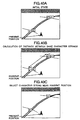
data plotting processing 1067 divides the region in which the map is practically displayed into a plurality of zones in the depth-wise direction, and applies necessary processing in each region. The explanation will be given hereby on the case where the region is divided into four zones. First, whether or not the route data exists in the foremostfront side region 1 inclusive of the present position is judged (step 1120) and when the result proves YES, the line width for displaying the route is set to the greatest width (e.g. 9-dot width; step 1121). Next, whether or not the route data exists in theregion 2 above theregion 1 is judged (step 1122) and when the result proves YES, the line width representing the route is set to the width smaller than that of thestep 1121 but greater than that of the step 1125 (e.g. 7-dot width: step 1123). Next, whether or not the route data exists in theregion 3 above theregion 2 is judged (step 1124), and when the result proves YES, the line width representing the route is set to the width smaller than that of thestep 1123 but greater than that of the step 1127 (e.g. 5-dot width; step 1125). Finally, whether or not the route data exists in thedeepest region 4 is judged (step 1126) and when the result proves YES, the line width representing the route is set to a width smaller than that of the step 1125 (e.g. 3-dot width; step 1127). When plotting is carried out in this manner, the forehand route can be displayed thinly and the depth route, thickly, as shown in Fig. 42B unlike the prior art system which does not have the feel of three-dimensional depth shown in Fig. 42A. Accordingly, the driver can recognize very naturally the route data. Incidentally, the explanation is hereby given on the system which divides the region and changes the line width for each divided region. However, it is also possible to employ the method which displays the routes close to the present position by a thicker line and the routes away from the present position by a thinner line. - Next, whether or not the orbit data exists in the plotting data is judged (step 1068). When the orbit data is judged as existing, the processing shifts to the orbit data plotting processing (step 1069) shown in Fig. 20. Incidentally, this orbit data is stored in the orbit memory means 69 storing therein the driving position in a predetermined distance interval. Generally, when the orbit data is displayed on the map by bird's-eye view map display, the gap of the points representing the orbit near the present position becomes great, whereas the gap of the points representing the orbit becomes small at the positions away from the present position. Therefore, there occurs the case from time to time where the points of the orbit overlap with one another. To solve this problem, in the orbit data plotting processing (step 1069), orbit thinning-out region judgement means (step 1140) for judging whether the region for which the orbit is to be plotted is away from the present position, switches the processing to the
step 1141 if the orbit is the orbit of the position away from the present position. Thinning-out data quantity calculation means (step 1141) decides the thinning-out quantity of the orbit data displayed so that the gap of the points representing the orbit becomes easily comprehensible when bird's-eye view map display is executed (step 1141). The orbit thinning-out processing (step 1142) thins out the orbit data, which need not be displayed, from the data to be displayed in accordance with the thinning-out quantity of the orbit data determined by thestep 1141, and prevents the orbit data from being displayed for the positions away from the present position. Next, the orbit interpolation region judgement means (step 1143) for judging if the region for which the orbit is to be plotted is near the present position, judges whether or not the orbit to be displayed is near the present position, and when the orbit is judged as being near the present position, the processing shifts to thestep 1144. The interpolation data quantity calculation means (step 1144) decides the orbit data quantity to be interpolated afresh between the orbit and the orbit so that the gap of the points representing the orbit reaches the comprehensible data quantity when bird's-eye view map display is executed (step 1144). The orbit interpolation processing sets the orbit data to be afresh displayed between the orbit and the orbit and on the driving road in accordance with the interpolation quantity of the orbit data decided by thestep 1144, prevents the interval between the orbit data from becoming too great and displays comprehensibly the roads that have been taken in the proximity of the present position (step 1145). - Next, the orbit display examples are shown in Figs. 43A and B. In the prior art system, the orbit data represented by the circle o is displayed in such a manner as to broaden at portions in the proximity of the present position and to narrow at portions away from the present position as shown in Fig. 43A. In the present system, on the other hand, the orbit data is displayed in the equal gaps at the portions in the proximity of the present position and at the portion away from it as shown in Fig. 43B. Accordingly, display quality can be improved and the roads containing the orbits can be more easily recognized. Therefore, the orbit recognition factor by the driver can be improved.
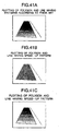
- The explanation given above explains the plotting processing method of the objects constituting the bird's-eye view map. Next, the method of plotting the artificial background such as the sky and the horizontal line will be explained. One of the problems encountered in bird's-eye view map is that when the map of the far places from the present position is displayed as shown in Fig. 44A, its reduced scale becomes small, an extremely enormous quantity of map data are necessary in plotting, an elongated time is necessary for display and high speed response cannot be obtained. To solve this problem, the Applicant of the present invention has proposed the method which limits the far region from the present position to be displayed in the map so as to reduce the map data quantity and displays insteads the artificial objects such as the horizontal line, the sky, and so forth. More concretely, the display region judgement means 81 shown in Fig. 8 decides the region to be displayed practically on the map. After the bird's-eye view map is displayed through the
subsequent steps 82 to 85, the artificial background setting means 86 sets the data of the artificial background. The content of this processing will be explained with reference to Fig. 21. First, an artificial background region calculation (step 1161) reads out the region information whose map is decided to be displayed by the display region judgement means 81, and decides the region for which the artificial background is displayed, from the difference between this region information and the screen size information. Next, artificial background color decision means (step 1162) and artificial background pattern setting means (step 1163) decide the colors of the background region and its pattern on the basis of various information such as the car information and the time information. The method of deciding the colors on the basis of the car information will be hereby explained by way of example. The car information S10 is inputted to the processor portion through thecar LAN 11. When the small lamp is lit at this time, it means that the surroundings are dark and the time can be judged as night. Therefore, the artificial background is displayed in black or grey. When the small lamp is not lit, the time can be judged as daytime. Therefore, the artificial background is displayed in blue. When the blue color cannot be displayed due to the color palette, it is advisable to conduct dither processing which sets the pattern so that the blue color and the white color are sequentially displayed. - Next, another embodiment which obtains the similar effect by a different means will be explained. In the navigation apparatus, the date and the time can be acquired by receiving and analyzing the signals from the GPS satellite. The artificial background can be displayed by using this information so that the blue color is displayed when the time is judged as the daytime and the black color or the grey when it is judged as the night. The artificial background may be displayed in read representing the morning or evening glow for the morning or the evening. Next, still another embodiment for obtaining the similar effect by a different means will be explained. This is the system which displays the artificial background in the blue when it is fine and in the grey when it is rainy or cloudy, by using the weather information contained in the information S9 received by the
traffic information receiver 10. Since the artificial background is displayed in match with the surrounding conditions by these means, the driver can easily judge what is represented by the artificial background. - Next, display means for the additional information such as the means to be displayed in superposition with the bird's-eye view map will be explained. The navigation apparatus for displaying the bird's-eye view map improves the user interface by displaying the information representing by which system the map presently displayed is plotted, in superposition with the map. Menu plotting means 70 for executing this processing will be explained with reference to Fig. 22. The content of the user's operation is transmitted by the
input device 5 to the user operation analysis means 61, where the content is analyzed. When the necessity of display by the menu plotting means 70 is judged as existing, the content is transmitted to the menu plotting means 70 by using a message. Receiving this message, the menu plotting means starts its processing and judges whether or not the request of this message is the display request of the plan view map (step 1180). When the message is judged as the one requesting the display of the plan view map, a mark representing that the plan view map such as shown at the lower left of Fig. 45A is now being displayed is displayed (step 1181). Further, the mark representing the reduced scale of the map displayed at present is displayed (at the lower right of Fig. 45A; step 1182). When the message is not the one described above, whether or not the request of the message is the display request of the bird's-eye view map is judged (step 1183). When it is judged as the message requesting display of the bird's-eye view map, the mark representing that the bird's-eye view map is now being displayed, such as the one shown at the lower left of Fig. 45B, is displayed (step 1184). Further, the mark representing the reduced scale of the map presently displayed is turned off (step 1185). When the message is not the one described above (step 1186), whether or not the request of the message is the change request of the projection angle in the bird's-eye view map is judged (step 1186). When it is judged as the message requesting the change of the projection angle, the shape of the mark representing the present position is changed in accordance with the projection angle in the same way as the present position mark in Figs. 45A and B (step 1187). When the projection angle e is close to 0° at this time, that is, when the map is close to the plan view, the present position mark is brought into conformity with the present position mark shape in the plan view map display, and as the projection angle e approaches 90°, the mark subjected to perspective conversion by the projection angle e at which the present position mark is set is used for display. As a result of the processing described above, the driver can easily judge the display mode of the map and the display region, so that recognition performance can be improved. - The foregoing embodiments can reduce overlap of the character strings in the bird's-eye view map display, eliminate the necessary for the user to estimate what is the character string displayed, from the relation between the preceding and subsequent character strings, and can make the character strings and the symbols more easily comprehensible. Because the bird's-eye view map is easily recognizable even while the driver is driving, safety can be further improved.
- Since display of the same character string is eliminated in the bird's-eye view map display, the bird's-eye view map can be displayed more simply. In consequence, the bird's-eye view map can be recognized more easily even while the driver is driving, and safety can be further improved.
- Because the route near the visual point is displayed more thickly than the routes away from the visual point in the bird's-eye view map display, the map can be expressed more three-dimensionally. Therefore, the user can easily acquire the feel of depth of the bird's-eye view map, and a more comprehensible map can be obtained.
- Further, because the dot strings representing the driving orbit in the bird's-eye view map display are expressed with suitable gap at both portions away from the visual point and portions near the visual point, the phenomenon in which the gaps of the dot strings representing the orbit becomes great, that occurs in the proximity of the visual point, as well as the phenomenon in which the gaps of the dot strings representing the orbit becomes narrower than necessary, that occurs at portions away from the visual point, can be avoided, and display quality of the bird's-eye view map and the driving orbit can be improved.
- Display quality of the patterns contained in the lines and the planes in the bird's-eye view map display somewhat drops, but because the display time can be shortened, the time necessary for displaying the bird's-eye view map becomes shorter. Therefore, the re-display cycle of the bird's-eye view map becomes shorter, and the bird's-eye view map can be displayed more really.
- The artificial background representing the virtual sky and horizontal line are so displayed as to correspond to the surrounding condition in the bird's-eye view map display. Therefore, the user is not perplexed unnecessary.
- Further, the user can easily judge that the map presently displayed is the bird's-eye view map or the plan view map. Since the present condition is displayed in such a manner as to correspond to the change of the visual point, the navigation apparatus becomes easier to use and safety can be improved.
- Since the destination is always displayed in a predetermined direction, the driver can drive the car while confirming always the direction of the destination.
- Since the information desired by the driver is preferentially displayed, the necessity for the driver to conduct unnecessary operations decreases during driving, safety can be therefore improved further.
Claims (2)
- A map display apparatus mountable to a car, the map display apparatus comprising:memory means (3) for storing map data necessary for plotting a map of a predetermined region;map display means (65) for displaying a bird's eye view map by using the map data read out from said memory means;display region limiting means (81) for limiting regions for bird's-eye view display to those regions existing on the foreground side from a disappearing point of perspective conversion;background display means (86) for displaying an artificial background such as a horizontal line and sky in the regions for which map display is limited by said display region limiting means; andbackground region control means (86) for changing colors andpatterns of the artificial background regions displayed by said background display means,characterized in that
said background region control means (86) changes the colors or patterns of the artificial background region in accordance with signals from a car having said map display apparatus mounted thereto or with the condition of said car. - A map display apparatus according to claim 1,
wherein said background region control means (86) changes the colors or patterns of the artificial background region in accordance with the ON/OFF state of lamps of the car having said map display apparatus mounted thereto.
Applications Claiming Priority (3)
| Application Number | Priority Date | Filing Date | Title |
|---|---|---|---|
| JP9477295 | 1995-04-20 | ||
| JP09477295A JP3568621B2 (en) | 1995-04-20 | 1995-04-20 | Map display device |
| EP96106194A EP0738876B1 (en) | 1995-04-20 | 1996-04-19 | Map display apparatus |
Related Parent Applications (1)
| Application Number | Title | Priority Date | Filing Date |
|---|---|---|---|
| EP96106194A Division EP0738876B1 (en) | 1995-04-20 | 1996-04-19 | Map display apparatus |
Publications (3)
| Publication Number | Publication Date |
|---|---|
| EP1260792A2 EP1260792A2 (en) | 2002-11-27 |
| EP1260792A3 EP1260792A3 (en) | 2003-11-05 |
| EP1260792B1 true EP1260792B1 (en) | 2007-05-23 |
Family
ID=14119395
Family Applications (2)
| Application Number | Title | Priority Date | Filing Date |
|---|---|---|---|
| EP96106194A Expired - Lifetime EP0738876B1 (en) | 1995-04-20 | 1996-04-19 | Map display apparatus |
| EP02012320A Expired - Lifetime EP1260792B1 (en) | 1995-04-20 | 1996-04-19 | Map Display Apparatus with Artificial Background |
Family Applications Before (1)
| Application Number | Title | Priority Date | Filing Date |
|---|---|---|---|
| EP96106194A Expired - Lifetime EP0738876B1 (en) | 1995-04-20 | 1996-04-19 | Map display apparatus |
Country Status (5)
| Country | Link |
|---|---|
| US (4) | US5917436A (en) |
| EP (2) | EP0738876B1 (en) |
| JP (1) | JP3568621B2 (en) |
| KR (1) | KR100406889B1 (en) |
| DE (2) | DE69637102T2 (en) |
Families Citing this family (169)
| Publication number | Priority date | Publication date | Assignee | Title |
|---|---|---|---|---|
| US6654014B2 (en) | 1995-04-20 | 2003-11-25 | Yoshinori Endo | Bird's-eye view forming method, map display apparatus and navigation system |
| JP3474022B2 (en) * | 1995-04-20 | 2003-12-08 | 株式会社日立製作所 | Map display device, map display method, arithmetic processing unit for map display device, and navigation system |
| JPH09230783A (en) * | 1996-02-26 | 1997-09-05 | Nissan Motor Co Ltd | Map display device |
| JPH1089976A (en) * | 1996-09-13 | 1998-04-10 | Hitachi Ltd | Information display and navigation system |
| JP3568357B2 (en) * | 1997-05-02 | 2004-09-22 | パイオニア株式会社 | Map information display device and map information display method in navigation device, and computer-readable recording medium storing map information display control program in navigation device |
| JP3623239B2 (en) * | 1997-06-20 | 2005-02-23 | 三菱電機株式会社 | Mobile information map information display device |
| JP3317211B2 (en) * | 1997-09-24 | 2002-08-26 | 松下電器産業株式会社 | Map editing device |
| JP3511570B2 (en) * | 1998-03-06 | 2004-03-29 | パイオニア株式会社 | Map information display device and recording medium recording navigation program |
| US6611753B1 (en) | 1998-04-17 | 2003-08-26 | Magellan Dis, Inc. | 3-dimensional intersection display for vehicle navigation system |
| US6259989B1 (en) * | 1998-06-12 | 2001-07-10 | Mitsubishi Denki K.K. | Navigation device |
| JP2000029598A (en) * | 1998-07-13 | 2000-01-28 | Matsushita Electric Ind Co Ltd | Device and method for controlling display and computer- readable recording medium recording display control program |
| US20020054082A1 (en) * | 1999-01-02 | 2002-05-09 | Karpf Ronald S. | System and method for providing accurate geocoding of responses to location questions in a computer assisted self interview |
| JP4486175B2 (en) | 1999-01-29 | 2010-06-23 | 株式会社日立製作所 | 3D map display apparatus and method |
| DE19920709A1 (en) * | 1999-05-05 | 2000-11-16 | Siemens Ag | Method for obtaining a three-dimensional map display and navigation system |
| JP3954242B2 (en) * | 1999-06-02 | 2007-08-08 | 松下電器産業株式会社 | Car navigation system |
| DE19929587A1 (en) | 1999-06-29 | 2001-01-04 | Volkswagen Ag | Display device, in particular for a motor vehicle |
| JP4054484B2 (en) * | 1999-06-30 | 2008-02-27 | 本田技研工業株式会社 | Map information display system for moving objects |
| US6587689B1 (en) * | 1999-08-19 | 2003-07-01 | Texas Instruments Incorporated | Multi-sensor assisted cellular handoff technique |
| DE19941477A1 (en) | 1999-09-01 | 2001-03-22 | Bosch Gmbh Robert | Navigation device for a land vehicle |
| DE19941961B4 (en) * | 1999-09-03 | 2008-10-23 | Volkswagen Ag | navigation system |
| JP3908419B2 (en) | 1999-09-14 | 2007-04-25 | アルパイン株式会社 | Navigation device |
| GB9928682D0 (en) * | 1999-12-06 | 2000-02-02 | Electrotextiles Comp Ltd | Input apparatus and a method of generating control signals |
| US6424933B1 (en) * | 2000-03-17 | 2002-07-23 | Vicinity Corporation | System and method for non-uniform scaled mapping |
| WO2001071484A1 (en) * | 2000-03-17 | 2001-09-27 | Vicinity Corp. | System and method for non-uniform scaled mapping |
| FI20001374A0 (en) * | 2000-06-09 | 2000-06-09 | Arcus Software Oy | Method for Communicating Data and Memory Capacity of a Workstation Using a 3D Model |
| JP4414076B2 (en) | 2000-08-30 | 2010-02-10 | 本田技研工業株式会社 | Mobile navigation system |
| US6536123B2 (en) | 2000-10-16 | 2003-03-25 | Sensation, Inc. | Three-axis magnetic sensor, an omnidirectional magnetic sensor and an azimuth measuring method using the same |
| US6904160B2 (en) * | 2000-10-18 | 2005-06-07 | Red Hen Systems, Inc. | Method for matching geographic information with recorded images |
| JP3695315B2 (en) * | 2000-11-14 | 2005-09-14 | 日産自動車株式会社 | Vehicle display device |
| JP3568159B2 (en) | 2001-03-15 | 2004-09-22 | 松下電器産業株式会社 | Three-dimensional map object display device and method, and navigation device using the method |
| US6591168B2 (en) * | 2001-08-31 | 2003-07-08 | Intellisist, Inc. | System and method for adaptable mobile user interface |
| US7746292B2 (en) | 2001-04-11 | 2010-06-29 | Kyocera Wireless Corp. | Reconfigurable radiation desensitivity bracket systems and methods |
| US7221243B2 (en) * | 2001-04-11 | 2007-05-22 | Kyocera Wireless Corp. | Apparatus and method for combining electrical signals |
| US7174147B2 (en) * | 2001-04-11 | 2007-02-06 | Kyocera Wireless Corp. | Bandpass filter with tunable resonator |
| US7154440B2 (en) * | 2001-04-11 | 2006-12-26 | Kyocera Wireless Corp. | Phase array antenna using a constant-gain phase shifter |
| US6690251B2 (en) * | 2001-04-11 | 2004-02-10 | Kyocera Wireless Corporation | Tunable ferro-electric filter |
| JP2002311821A (en) * | 2001-04-13 | 2002-10-25 | Mitsubishi Electric Corp | Map display method for navigation and navigation device |
| US7269632B2 (en) | 2001-06-05 | 2007-09-11 | Xdyne, Inc. | Networked computer system for communicating and operating in a virtual reality environment |
| JP4132741B2 (en) * | 2001-07-25 | 2008-08-13 | アルパイン株式会社 | Navigation device |
| JP4688198B2 (en) * | 2001-07-31 | 2011-05-25 | パイオニア株式会社 | MAP INFORMATION DISPLAY SYSTEM, MAP INFORMATION DISPLAY METHOD, SERVER DEVICE, AND TERMINAL DEVICE |
| JP2003042772A (en) | 2001-07-31 | 2003-02-13 | Pioneer Electronic Corp | Communication navigation system, communication navigation method, path-guiding information transmission apparatus, and terminal apparatus |
| JP2003042790A (en) * | 2001-08-01 | 2003-02-13 | Pioneer Electronic Corp | Communication navigation system, communication navigation method, terminal apparatus, and path guidance information transmission apparatus |
| JP2003065783A (en) | 2001-08-27 | 2003-03-05 | Pioneer Electronic Corp | Communication navigation system and method for the same, device for communication center for providing map information, communication navigation terminal and computer program |
| EP1288625B1 (en) * | 2001-08-31 | 2011-07-27 | Pioneer Corporation | Communication-type navigation apparatus and server device |
| US7466992B1 (en) * | 2001-10-18 | 2008-12-16 | Iwao Fujisaki | Communication device |
| JP4240446B2 (en) * | 2002-06-24 | 2009-03-18 | 富士通テン株式会社 | Image display device |
| US20030148772A1 (en) * | 2002-02-05 | 2003-08-07 | Haim Ben-Ari | System and method for generating a directional indicator on a wireless communications device display |
| US7180467B2 (en) * | 2002-02-12 | 2007-02-20 | Kyocera Wireless Corp. | System and method for dual-band antenna matching |
| US7184727B2 (en) * | 2002-02-12 | 2007-02-27 | Kyocera Wireless Corp. | Full-duplex antenna system and method |
| US7176845B2 (en) * | 2002-02-12 | 2007-02-13 | Kyocera Wireless Corp. | System and method for impedance matching an antenna to sub-bands in a communication band |
| US7243134B2 (en) * | 2002-06-25 | 2007-07-10 | Motorola, Inc. | Server-based navigation system having dynamic transmittal of route information |
| JP2004078070A (en) * | 2002-08-22 | 2004-03-11 | Denso Corp | Navigation system |
| US20040044465A1 (en) * | 2002-08-29 | 2004-03-04 | Nesbitt David W. | Automated route determination based on day of route traversal |
| US8560223B2 (en) | 2002-08-29 | 2013-10-15 | Mapquest, Inc. | Automated route determination |
| US7133771B1 (en) | 2002-08-29 | 2006-11-07 | America Online, Inc. | Automated route determination to avoid a particular maneuver |
| US7417641B1 (en) * | 2002-10-16 | 2008-08-26 | Rockwell Collins, Inc. | Aeronautical chart display apparatus and method |
| WO2004059996A1 (en) * | 2002-12-27 | 2004-07-15 | Nokia Corporation | Location based services for mobile communication terminals |
| US7818116B1 (en) * | 2002-12-30 | 2010-10-19 | Mapquest, Inc. | Presenting a travel route in a ground-based vehicle |
| US7321824B1 (en) * | 2002-12-30 | 2008-01-22 | Aol Llc | Presenting a travel route using more than one presentation style |
| US7474960B1 (en) * | 2002-12-30 | 2009-01-06 | Mapquest, Inc. | Presenting a travel route |
| KR101168423B1 (en) * | 2003-02-05 | 2012-07-25 | 가부시키가이샤 자나비 인포메틱스 | Path search method of navigation apparatus and display method of traffic information |
| US7570261B1 (en) * | 2003-03-06 | 2009-08-04 | Xdyne, Inc. | Apparatus and method for creating a virtual three-dimensional environment, and method of generating revenue therefrom |
| US20050128212A1 (en) * | 2003-03-06 | 2005-06-16 | Edecker Ada M. | System and method for minimizing the amount of data necessary to create a virtual three-dimensional environment |
| US6836713B2 (en) * | 2003-04-03 | 2004-12-28 | Coato Workshop, Inc. | Navigational method and device for user interface for motor vehicles |
| US20040243307A1 (en) * | 2003-06-02 | 2004-12-02 | Pieter Geelen | Personal GPS navigation device |
| US7720443B2 (en) | 2003-06-02 | 2010-05-18 | Kyocera Wireless Corp. | System and method for filtering time division multiple access telephone communications |
| US7562289B2 (en) * | 2003-06-18 | 2009-07-14 | Layton Geo-Science, Inc. | Methods and systems for encoding geographic coordinates and features in a portable document format file |
| US7065448B1 (en) | 2003-10-01 | 2006-06-20 | America Online, Inc. | Presenting driving directions |
| KR100520707B1 (en) * | 2003-10-20 | 2005-10-17 | 엘지전자 주식회사 | Method for displaying multi-level text data in three dimensional map |
| JP4646538B2 (en) * | 2004-03-26 | 2011-03-09 | アルパイン株式会社 | Electronic device having navigation function and night view map display method |
| JP2005321370A (en) * | 2004-04-05 | 2005-11-17 | Sony Corp | Navigation system, data processing method and computer program |
| JP4436186B2 (en) * | 2004-05-12 | 2010-03-24 | アルパイン株式会社 | Navigation device and map display method |
| US8453065B2 (en) | 2004-06-25 | 2013-05-28 | Apple Inc. | Preview and installation of user interface elements in a display environment |
| US7490295B2 (en) | 2004-06-25 | 2009-02-10 | Apple Inc. | Layer for accessing user interface elements |
| US8566732B2 (en) | 2004-06-25 | 2013-10-22 | Apple Inc. | Synchronization of widgets and dashboards |
| US8751156B2 (en) | 2004-06-30 | 2014-06-10 | HERE North America LLC | Method of operating a navigation system using images |
| FR2872620B1 (en) * | 2004-06-30 | 2006-11-10 | Siemens Vdo Automotive Sas | METHOD FOR MANAGING OVERLAYS OF GRAPHIC OBJECTS WHEN DISPLAYING A CARD |
| US20060002590A1 (en) * | 2004-06-30 | 2006-01-05 | Borak Jason M | Method of collecting information for a geographic database for use with a navigation system |
| US7460953B2 (en) * | 2004-06-30 | 2008-12-02 | Navteq North America, Llc | Method of operating a navigation system using images |
| US7966003B2 (en) * | 2004-07-09 | 2011-06-21 | Tegic Communications, Inc. | Disambiguating ambiguous characters |
| US20070091375A1 (en) * | 2004-07-14 | 2007-04-26 | Kabushiki Kaisha Giskyushu | Optimum character string placing program |
| DE102004038739A1 (en) * | 2004-08-10 | 2006-02-23 | Robert Bosch Gmbh | Method for displaying map information |
| US7949642B2 (en) * | 2004-10-12 | 2011-05-24 | Wendy W Yang | System and method for managing and presenting entity information |
| EP1650533A1 (en) * | 2004-10-20 | 2006-04-26 | France Telecom | Procedure for selecting landmarks in a route |
| JP2006132132A (en) * | 2004-11-04 | 2006-05-25 | Hitachi Constr Mach Co Ltd | Work management device and working machine equipped therewith |
| US7376510B1 (en) * | 2004-11-05 | 2008-05-20 | Navteq North America, Llc | Map display for a navigation system |
| JP4234089B2 (en) * | 2004-11-16 | 2009-03-04 | 株式会社ソニー・コンピュータエンタテインメント | Entertainment device, object display device, object display method, program, and character display method |
| US7395153B1 (en) | 2004-12-23 | 2008-07-01 | Aol Llc | Reducing driving directions |
| US7689349B1 (en) | 2004-12-23 | 2010-03-30 | Aol Llc | Automatic determination of a surrogate origin for personalized routing |
| US8108142B2 (en) * | 2005-01-26 | 2012-01-31 | Volkswagen Ag | 3D navigation system for motor vehicles |
| US20060206265A1 (en) * | 2005-03-08 | 2006-09-14 | John Cross | GPS device and method for displaying two locations simultaneously |
| JP4596978B2 (en) * | 2005-03-09 | 2010-12-15 | 三洋電機株式会社 | Driving support system |
| US20060253246A1 (en) * | 2005-04-18 | 2006-11-09 | Cera Christopher D | Data-driven combined traffic/weather views |
| US8626440B2 (en) * | 2005-04-18 | 2014-01-07 | Navteq B.V. | Data-driven 3D traffic views with the view based on user-selected start and end geographical locations |
| US7765055B2 (en) | 2005-04-18 | 2010-07-27 | Traffic.Com, Inc. | Data-driven traffic views with the view based on a user-selected object of interest |
| US8781736B2 (en) * | 2005-04-18 | 2014-07-15 | Navteq B.V. | Data-driven traffic views with continuous real-time rendering of traffic flow map |
| US20060241859A1 (en) * | 2005-04-21 | 2006-10-26 | Microsoft Corporation | Virtual earth real-time advertising |
| WO2006121986A2 (en) | 2005-05-06 | 2006-11-16 | Facet Technology Corp. | Network-based navigation system having virtual drive-thru advertisements integrated with actual imagery from along a physical route |
| JP4690114B2 (en) | 2005-05-23 | 2011-06-01 | パイオニア株式会社 | Information updating apparatus, method thereof, program thereof, and recording medium recording the program |
| JP4326502B2 (en) * | 2005-05-26 | 2009-09-09 | 任天堂株式会社 | Image processing program and image processing apparatus for moving display area |
| US8543931B2 (en) * | 2005-06-07 | 2013-09-24 | Apple Inc. | Preview including theme based installation of user interface elements in a display environment |
| JP4715353B2 (en) * | 2005-07-19 | 2011-07-06 | 株式会社セガ | Image processing apparatus, drawing method, and drawing program |
| JP2007026201A (en) * | 2005-07-19 | 2007-02-01 | Sega Corp | Image processor, road image drawing method and road image drawing program |
| JP4783603B2 (en) * | 2005-08-26 | 2011-09-28 | 株式会社デンソー | MAP DISPLAY DEVICE, MAP DISPLAY METHOD, MAP DISPLAY PROGRAM, AND RECORDING MEDIUM CONTAINING THE PROGRAM |
| US7743336B2 (en) | 2005-10-27 | 2010-06-22 | Apple Inc. | Widget security |
| US7752556B2 (en) | 2005-10-27 | 2010-07-06 | Apple Inc. | Workflow widgets |
| US8543824B2 (en) | 2005-10-27 | 2013-09-24 | Apple Inc. | Safe distribution and use of content |
| US9104294B2 (en) | 2005-10-27 | 2015-08-11 | Apple Inc. | Linked widgets |
| US7954064B2 (en) | 2005-10-27 | 2011-05-31 | Apple Inc. | Multiple dashboards |
| US7707514B2 (en) * | 2005-11-18 | 2010-04-27 | Apple Inc. | Management of user interface elements in a display environment |
| US7548762B2 (en) * | 2005-11-30 | 2009-06-16 | Kyocera Corporation | Method for tuning a GPS antenna matching network |
| AU2006330465B2 (en) | 2005-12-24 | 2011-04-07 | Joshua D I Distler | Methods and files for delivering imagery with embedded data |
| WO2007096952A1 (en) * | 2006-02-22 | 2007-08-30 | Navitime Japan Co., Ltd. | Map display system, map display method for map display system, map display device, and program |
| DE102006010615A1 (en) * | 2006-03-08 | 2007-09-13 | Bayerische Motoren Werke Ag | Map information displaying method for vehicle`s navigation system, involves representating map information in bird`s eye view, and representating additional information over map information |
| TWI290214B (en) * | 2006-04-04 | 2007-11-21 | Mitac Int Corp | Method of modified navigation information map with discriminated function and the apparatus thereof |
| KR100852615B1 (en) | 2006-04-27 | 2008-08-18 | 팅크웨어(주) | System and method for expressing map according to change season and topography |
| JP4551355B2 (en) * | 2006-05-12 | 2010-09-29 | 株式会社日立製作所 | 3D map display device |
| DE102006033347A1 (en) * | 2006-07-19 | 2008-01-31 | Eads Deutschland Gmbh | Method for determining optimized trajectories of vehicles |
| JPWO2008010276A1 (en) * | 2006-07-20 | 2009-12-17 | 株式会社ナビタイムジャパン | Map display system, map display device, map display method, and map distribution server |
| FR2904107A1 (en) * | 2006-07-24 | 2008-01-25 | Viamichelin Soc Par Actions Si | METHOD AND GUIDE DEVICE FOR VEHICLE WITH MULTI-MODE DISPLAY |
| US8869027B2 (en) | 2006-08-04 | 2014-10-21 | Apple Inc. | Management and generation of dashboards |
| US7684017B2 (en) | 2006-10-26 | 2010-03-23 | Callaway Golf Company | Laser range finder for use on a golf course |
| JP4850133B2 (en) * | 2007-06-06 | 2012-01-11 | アルパイン株式会社 | Map display device and map display method |
| US20080309762A1 (en) * | 2007-06-12 | 2008-12-18 | Richie Howard | In-vehicle mobile digital video surveillance recorder system with GPS visual mapping and navigation |
| US8954871B2 (en) | 2007-07-18 | 2015-02-10 | Apple Inc. | User-centric widgets and dashboards |
| US8667415B2 (en) | 2007-08-06 | 2014-03-04 | Apple Inc. | Web widgets |
| US8554475B2 (en) | 2007-10-01 | 2013-10-08 | Mitac International Corporation | Static and dynamic contours |
| KR101365348B1 (en) * | 2007-12-18 | 2014-02-21 | 삼성전자주식회사 | Message exchanging method in navigation system using visible light communication |
| US20090263026A1 (en) * | 2008-04-18 | 2009-10-22 | Google Inc. | Content item placement |
| US20100070175A1 (en) * | 2008-09-15 | 2010-03-18 | Navteq North America, Llc | Method and System for Providing a Realistic Environment for a Traffic Report |
| JP4631959B2 (en) * | 2008-10-29 | 2011-02-16 | 三菱電機株式会社 | Mobile navigation device and map image display method |
| CN101655375B (en) * | 2009-07-28 | 2011-09-14 | 北京四维图新科技股份有限公司 | Method for automatically dividing display level of character marks in navigation electronic map and device thereof |
| US9552726B2 (en) | 2009-08-24 | 2017-01-24 | Here Global B.V. | Providing driving condition alerts using road attribute data |
| JP5554045B2 (en) * | 2009-10-21 | 2014-07-23 | アルパイン株式会社 | Map display device and map display method |
| JP2011134192A (en) * | 2009-12-25 | 2011-07-07 | Casio Computer Co Ltd | Device, method and program for displaying character string |
| US9373193B2 (en) * | 2010-01-07 | 2016-06-21 | Suzhou Xintu Geographic Information Technology Co., Ltd | Method and apparatus for detecting and avoiding conflicts of space entity element annotations |
| JP5402769B2 (en) * | 2010-03-24 | 2014-01-29 | 株式会社デンソー | Reference map data switching method in navigation device |
| JP5244846B2 (en) * | 2010-04-06 | 2013-07-24 | 京セラドキュメントソリューションズ株式会社 | Display input device and image forming apparatus having the same |
| JP5521717B2 (en) * | 2010-04-07 | 2014-06-18 | トヨタ自動車株式会社 | Image display method |
| US8423902B2 (en) * | 2010-04-21 | 2013-04-16 | Microsoft Corporation | Representation of overlapping visual entities |
| JP5251927B2 (en) * | 2010-06-21 | 2013-07-31 | 日産自動車株式会社 | Moving distance detection device and moving distance detection method |
| KR101448411B1 (en) | 2010-08-19 | 2014-10-07 | 닛산 지도우샤 가부시키가이샤 | Three-dimensional object detection device and three -dimensional object detection method |
| US8902219B1 (en) | 2010-09-22 | 2014-12-02 | Trimble Navigation Limited | Maintaining connection to embedded content using graphical elements |
| US9076244B2 (en) | 2011-06-29 | 2015-07-07 | Trimble Navigation Limited | Managing web page data in a composite document |
| US9411901B2 (en) * | 2011-06-29 | 2016-08-09 | Trimble Navigation Limited | Managing satellite and aerial image data in a composite document |
| WO2013024505A1 (en) * | 2011-08-15 | 2013-02-21 | 三菱電機株式会社 | Character string placement device |
| DE112012006524T5 (en) * | 2012-06-14 | 2015-03-05 | Mitsubishi Electric Corporation | String placement and signing device |
| DE102012020568A1 (en) * | 2012-10-19 | 2014-04-24 | Audi Ag | Method for operating e.g. computer of passenger car, involves reproducing detected property and nature in natural image of environment, combining natural image with map of environment, and transmitting combined graph to display device |
| US10108693B2 (en) | 2013-03-14 | 2018-10-23 | Xdyne, Inc. | System and method for interacting with virtual maps |
| JP5997640B2 (en) | 2013-03-25 | 2016-09-28 | 株式会社ジオ技術研究所 | 3D image output apparatus and background image generation apparatus |
| JP6179166B2 (en) * | 2013-04-16 | 2017-08-16 | アイシン・エィ・ダブリュ株式会社 | Point display system, method and program |
| US10139238B2 (en) * | 2013-09-11 | 2018-11-27 | Qualcomm Incorporated | Systems, methods, and apparatus related to guidance and alignment for an electric vehicle and charging station |
| US9582999B2 (en) | 2013-10-31 | 2017-02-28 | Here Global B.V. | Traffic volume estimation |
| US20170090460A1 (en) * | 2015-09-25 | 2017-03-30 | Microsoft Technology Licensing, Llc | 3D Model Generation From Map Data |
| US10032034B2 (en) | 2015-10-06 | 2018-07-24 | Microsoft Technology Licensing, Llc | MPEG transport frame synchronization |
| CN106767858A (en) * | 2015-11-24 | 2017-05-31 | 英业达科技有限公司 | Traffic route planning system |
| DE102016200608A1 (en) * | 2016-01-19 | 2017-07-20 | Bayerische Motoren Werke Aktiengesellschaft | Method for arranging and displaying graphical elements of a representation of a vehicle navigation system |
| JP2017181632A (en) * | 2016-03-29 | 2017-10-05 | 株式会社ゼンリンデータコム | Map note processor, map note processing method, map note processing program, and map display device |
| EP3542134A4 (en) | 2016-11-21 | 2019-12-04 | Beijing Didi Infinity Technology and Development Co., Ltd. | Systems and methods for performing location-based actions |
| CN108460815B (en) * | 2017-02-22 | 2022-06-17 | 腾讯科技(深圳)有限公司 | Method and device for editing map road elements |
| CN108871350B (en) * | 2017-05-11 | 2021-05-18 | 北京嘀嘀无限科技发展有限公司 | Map navigation mode display method, display system and computer device |
| DE102017208867A1 (en) | 2017-05-24 | 2018-11-29 | Bayerische Motoren Werke Aktiengesellschaft | Presentation of a route by a navigation system |
| DE102017006849A1 (en) * | 2017-07-21 | 2019-01-24 | Lukas HEINDL | Method for determining the relative positions of at least two mobile terminals relative to one another |
| CN107886570B (en) * | 2017-09-22 | 2020-03-24 | 中国矿业大学 | Visual domain calculation method considering both precision and efficiency |
| CN108460725B (en) * | 2018-03-22 | 2019-06-18 | 腾讯科技(深圳)有限公司 | Map-indication method, device, equipment and storage medium |
| JP7259299B2 (en) * | 2018-12-05 | 2023-04-18 | トヨタ自動車株式会社 | Map image display device and computer program |
| JP7379956B2 (en) * | 2019-09-03 | 2023-11-15 | 富士フイルムビジネスイノベーション株式会社 | Image processing device and program |
| US20230017970A1 (en) * | 2019-12-26 | 2023-01-19 | Sony Semiconductor Solutions Corporation | Information processing device, mobile apparatus, information processing system, information processing method, and program |
| CN111915608B (en) * | 2020-09-11 | 2023-08-15 | 北京百度网讯科技有限公司 | Building extraction method, device, equipment and storage medium |
Citations (1)
| Publication number | Priority date | Publication date | Assignee | Title |
|---|---|---|---|---|
| US5366376A (en) * | 1992-05-22 | 1994-11-22 | Atari Games Corporation | Driver training system and method with performance data feedback |
Family Cites Families (30)
| Publication number | Priority date | Publication date | Assignee | Title |
|---|---|---|---|---|
| CA1295737C (en) * | 1986-03-14 | 1992-02-11 | Akira Ichikawa | Apparatus for displaying travel path |
| KR890002165A (en) * | 1987-07-27 | 1989-04-08 | 원본미기재 | Pyrrolo [1,2-a] [4,1] benzoxazepine derivatives |
| JP2606723B2 (en) * | 1988-04-15 | 1997-05-07 | 有限会社ヴェルク・ジャパン | Map display device for navigation |
| NL8900056A (en) * | 1989-01-11 | 1990-08-01 | Philips Nv | METHOD FOR VISUAL DISPLAY OF A PART OF A TOPOGRAPHIC MAP, AND APPARATUS SUITABLE FOR SUCH A METHOD |
| NL8901695A (en) * | 1989-07-04 | 1991-02-01 | Koninkl Philips Electronics Nv | METHOD FOR DISPLAYING NAVIGATION DATA FOR A VEHICLE IN AN ENVIRONMENTAL IMAGE OF THE VEHICLE, NAVIGATION SYSTEM FOR CARRYING OUT THE METHOD AND VEHICLE FITTING A NAVIGATION SYSTEM. |
| DE3930862A1 (en) * | 1989-09-15 | 1991-03-28 | Vdo Schindling | METHOD AND DEVICE FOR PRESENTING AIRPORT INFORMATION |
| US5299300A (en) * | 1990-02-22 | 1994-03-29 | Harris Corporation | Interpolation processing of digital map imagery data |
| US5448696A (en) * | 1990-11-30 | 1995-09-05 | Hitachi, Ltd. | Map information system capable of displaying layout information |
| JPH04288584A (en) * | 1991-03-18 | 1992-10-13 | Pioneer Electron Corp | Map display device |
| JPH0561405A (en) * | 1991-09-02 | 1993-03-12 | Nissin Electric Co Ltd | In-figure name display device |
| US5602564A (en) * | 1991-11-14 | 1997-02-11 | Hitachi, Ltd. | Graphic data processing system |
| JP3209774B2 (en) * | 1991-12-27 | 2001-09-17 | 富士通テン株式会社 | Map display device |
| US5377102A (en) | 1992-03-05 | 1994-12-27 | Nishiishigaki; Kenji | Apparatus for preparing map data with regional properties |
| JP2850634B2 (en) * | 1992-04-02 | 1999-01-27 | 日産自動車株式会社 | Vehicle navigation system |
| JP2759934B2 (en) * | 1992-09-07 | 1998-05-28 | 澁谷工業株式会社 | Dust removal device in gas laser device |
| JP3224303B2 (en) * | 1993-02-17 | 2001-10-29 | 富士通テン株式会社 | Display control device for navigation system |
| US5412573A (en) * | 1993-05-20 | 1995-05-02 | Motorola Inc. | Multi-mode route guidance system and method therefor |
| JPH07103783A (en) * | 1993-10-06 | 1995-04-18 | Daihatsu Motor Co Ltd | Map display method of navigation system |
| JPH07160845A (en) * | 1993-12-02 | 1995-06-23 | Fujitsu Ten Ltd | Map plotting device |
| EP0660290B1 (en) * | 1993-12-27 | 2000-07-12 | Nissan Motor Co., Ltd. | Apparatus and method for navigating vehicle to destination using display unit |
| JPH0868645A (en) * | 1994-08-29 | 1996-03-12 | Nissan Motor Co Ltd | Navigation system |
| US5793310A (en) * | 1994-02-04 | 1998-08-11 | Nissan Motor Co., Ltd. | Portable or vehicular navigating apparatus and method capable of displaying bird's eye view |
| EP0678731B1 (en) * | 1994-04-15 | 1999-06-30 | Nissan Motor Co., Ltd. | Vehicle navigation system |
| US5566073A (en) * | 1994-07-11 | 1996-10-15 | Margolin; Jed | Pilot aid using a synthetic environment |
| EP1455322B1 (en) * | 1994-11-14 | 2006-08-23 | Xanavi Informatics Corporation | Road map display apparatus for motor vehicle |
| JP3412296B2 (en) * | 1994-12-02 | 2003-06-03 | 日産自動車株式会社 | Route guidance device for vehicles |
| JP3391136B2 (en) * | 1995-02-24 | 2003-03-31 | 日産自動車株式会社 | Route guidance device for vehicles |
| DE69627932T2 (en) * | 1995-06-09 | 2004-02-26 | Xanavi Informatics Corp., Zama | A map display apparatus |
| JPH08335038A (en) * | 1995-06-09 | 1996-12-17 | Zanavy Informatics:Kk | Map display device for vehicle |
| JPH09230783A (en) * | 1996-02-26 | 1997-09-05 | Nissan Motor Co Ltd | Map display device |
-
1995
- 1995-04-20 JP JP09477295A patent/JP3568621B2/en not_active Expired - Fee Related
-
1996
- 1996-04-19 KR KR1019960011852A patent/KR100406889B1/en not_active IP Right Cessation
- 1996-04-19 US US08/636,767 patent/US5917436A/en not_active Expired - Lifetime
- 1996-04-19 EP EP96106194A patent/EP0738876B1/en not_active Expired - Lifetime
- 1996-04-19 EP EP02012320A patent/EP1260792B1/en not_active Expired - Lifetime
- 1996-04-19 DE DE69637102T patent/DE69637102T2/en not_active Expired - Lifetime
- 1996-04-19 DE DE69624863T patent/DE69624863T2/en not_active Expired - Lifetime
-
1999
- 1999-05-27 US US09/320,556 patent/US6278383B1/en not_active Expired - Lifetime
-
2001
- 2001-08-21 US US09/932,951 patent/US6603407B2/en not_active Expired - Lifetime
-
2003
- 2003-05-19 US US10/440,303 patent/US6756919B2/en not_active Expired - Fee Related
Patent Citations (1)
| Publication number | Priority date | Publication date | Assignee | Title |
|---|---|---|---|---|
| US5366376A (en) * | 1992-05-22 | 1994-11-22 | Atari Games Corporation | Driver training system and method with performance data feedback |
Also Published As
| Publication number | Publication date |
|---|---|
| DE69637102T2 (en) | 2008-01-24 |
| EP0738876B1 (en) | 2002-11-20 |
| KR960038702A (en) | 1996-11-21 |
| US5917436A (en) | 1999-06-29 |
| US6756919B2 (en) | 2004-06-29 |
| DE69624863T2 (en) | 2003-08-28 |
| EP0738876A3 (en) | 1999-02-10 |
| US6278383B1 (en) | 2001-08-21 |
| EP1260792A2 (en) | 2002-11-27 |
| DE69637102D1 (en) | 2007-07-05 |
| JPH08292715A (en) | 1996-11-05 |
| DE69624863D1 (en) | 2003-01-02 |
| EP0738876A2 (en) | 1996-10-23 |
| US20020011941A1 (en) | 2002-01-31 |
| US20030197626A1 (en) | 2003-10-23 |
| KR100406889B1 (en) | 2004-04-08 |
| JP3568621B2 (en) | 2004-09-22 |
| US6603407B2 (en) | 2003-08-05 |
| EP1260792A3 (en) | 2003-11-05 |
Similar Documents
| Publication | Publication Date | Title |
|---|---|---|
| EP1260792B1 (en) | Map Display Apparatus with Artificial Background | |
| US6421604B1 (en) | Map display apparatus for motor vehicle | |
| US5913918A (en) | Automotive navigation apparatus and recording medium storing program therefor | |
| US6654014B2 (en) | Bird's-eye view forming method, map display apparatus and navigation system | |
| US6346942B1 (en) | Bird's-eye view forming method, map display apparatus and navigation system | |
| KR0169153B1 (en) | Route guidance device for a vehicle | |
| US6710774B1 (en) | Map display device | |
| US5974876A (en) | Map information displaying apparatus, navigation apparatus and program storage device readable by the navigation apparatus | |
| KR100266882B1 (en) | Navigation device | |
| EP0965970A1 (en) | Three-dimensional map display device and data generating device used for it | |
| JPH09292830A (en) | Method and device for electronic map display | |
| JPH09281890A (en) | Map display device and navigation system | |
| JP3954178B2 (en) | 3D map display device | |
| JPH1144545A (en) | Navigator for displaying three-dimensional scenic view | |
| JP2003030687A (en) | Map display device | |
| JP3848351B2 (en) | Navigation device | |
| JP2003232639A (en) | Map display device and navigation device |
Legal Events
| Date | Code | Title | Description |
|---|---|---|---|
| PUAI | Public reference made under article 153(3) epc to a published international application that has entered the european phase |
Free format text: ORIGINAL CODE: 0009012 |
|
| AC | Divisional application: reference to earlier application |
Ref document number: 738876 Country of ref document: EP |
|
| AK | Designated contracting states |
Kind code of ref document: A2 Designated state(s): DE FR GB |
|
| RIN1 | Information on inventor provided before grant (corrected) |
Inventor name: ENDO, YOSHINORI Inventor name: FUJIWARA, TOSHIO Inventor name: SHOJIMA, HIROSHI Inventor name: HIRANO,MOTOKI Inventor name: AIKAWA, TETSUMORI Inventor name: HARADA,KAORU |
|
| RIN1 | Information on inventor provided before grant (corrected) |
Inventor name: FUJIWARA, TOSHIO Inventor name: AIKAWA, TETSUMORI Inventor name: HARADA,KAORU Inventor name: HIRANO,MOTOKI Inventor name: SHOJIMA, HIROSHI Inventor name: ENDO, YOSHINORI |
|
| PUAL | Search report despatched |
Free format text: ORIGINAL CODE: 0009013 |
|
| AK | Designated contracting states |
Kind code of ref document: A3 Designated state(s): DE FR GB |
|
| RIC1 | Information provided on ipc code assigned before grant |
Ipc: 7G 09B 29/00 B Ipc: 7G 01C 21/36 B Ipc: 7G 08G 1/0969 A |
|
| 17P | Request for examination filed |
Effective date: 20040225 |
|
| AKX | Designation fees paid |
Designated state(s): DE FR GB |
|
| 17Q | First examination report despatched |
Effective date: 20050705 |
|
| RTI1 | Title (correction) |
Free format text: MAP DISPLAY APPARATUS WITH ARTIFICIAL BACKGROUND |
|
| GRAP | Despatch of communication of intention to grant a patent |
Free format text: ORIGINAL CODE: EPIDOSNIGR1 |
|
| GRAS | Grant fee paid |
Free format text: ORIGINAL CODE: EPIDOSNIGR3 |
|
| RAP1 | Party data changed (applicant data changed or rights of an application transferred) |
Owner name: HITACHI, LTD. Owner name: XANAVI INFORMATICS CORPORATION |
|
| GRAA | (expected) grant |
Free format text: ORIGINAL CODE: 0009210 |
|
| AC | Divisional application: reference to earlier application |
Ref document number: 0738876 Country of ref document: EP Kind code of ref document: P |
|
| AK | Designated contracting states |
Kind code of ref document: B1 Designated state(s): DE FR GB |
|
| REG | Reference to a national code |
Ref country code: GB Ref legal event code: FG4D |
|
| REF | Corresponds to: |
Ref document number: 69637102 Country of ref document: DE Date of ref document: 20070705 Kind code of ref document: P |
|
| ET | Fr: translation filed | ||
| PLBE | No opposition filed within time limit |
Free format text: ORIGINAL CODE: 0009261 |
|
| STAA | Information on the status of an ep patent application or granted ep patent |
Free format text: STATUS: NO OPPOSITION FILED WITHIN TIME LIMIT |
|
| 26N | No opposition filed |
Effective date: 20080226 |
|
| REG | Reference to a national code |
Ref country code: FR Ref legal event code: PLFP Year of fee payment: 20 |
|
| PGFP | Annual fee paid to national office [announced via postgrant information from national office to epo] |
Ref country code: DE Payment date: 20150430 Year of fee payment: 20 Ref country code: GB Payment date: 20150420 Year of fee payment: 20 |
|
| PGFP | Annual fee paid to national office [announced via postgrant information from national office to epo] |
Ref country code: FR Payment date: 20150331 Year of fee payment: 20 |
|
| REG | Reference to a national code |
Ref country code: DE Ref legal event code: R071 Ref document number: 69637102 Country of ref document: DE |
|
| REG | Reference to a national code |
Ref country code: GB Ref legal event code: PE20 Expiry date: 20160418 |
|
| PG25 | Lapsed in a contracting state [announced via postgrant information from national office to epo] |
Ref country code: GB Free format text: LAPSE BECAUSE OF EXPIRATION OF PROTECTION Effective date: 20160418 |