EP1259080B1 - Picture transmission method, picture transmission method program, storage medium which stores picture transmission method program, and picture transmission apparatus - Google Patents
Picture transmission method, picture transmission method program, storage medium which stores picture transmission method program, and picture transmission apparatus Download PDFInfo
- Publication number
- EP1259080B1 EP1259080B1 EP20020009681 EP02009681A EP1259080B1 EP 1259080 B1 EP1259080 B1 EP 1259080B1 EP 20020009681 EP20020009681 EP 20020009681 EP 02009681 A EP02009681 A EP 02009681A EP 1259080 B1 EP1259080 B1 EP 1259080B1
- Authority
- EP
- European Patent Office
- Prior art keywords
- moving picture
- encoding
- picture data
- picture
- position information
- Prior art date
- Legal status (The legal status is an assumption and is not a legal conclusion. Google has not performed a legal analysis and makes no representation as to the accuracy of the status listed.)
- Expired - Fee Related
Links
Images

Classifications
-
- H—ELECTRICITY
- H04—ELECTRIC COMMUNICATION TECHNIQUE
- H04N—PICTORIAL COMMUNICATION, e.g. TELEVISION
- H04N19/00—Methods or arrangements for coding, decoding, compressing or decompressing digital video signals
- H04N19/30—Methods or arrangements for coding, decoding, compressing or decompressing digital video signals using hierarchical techniques, e.g. scalability
- H04N19/33—Methods or arrangements for coding, decoding, compressing or decompressing digital video signals using hierarchical techniques, e.g. scalability in the spatial domain
-
- H—ELECTRICITY
- H04—ELECTRIC COMMUNICATION TECHNIQUE
- H04N—PICTORIAL COMMUNICATION, e.g. TELEVISION
- H04N19/00—Methods or arrangements for coding, decoding, compressing or decompressing digital video signals
- H04N19/10—Methods or arrangements for coding, decoding, compressing or decompressing digital video signals using adaptive coding
- H04N19/134—Methods or arrangements for coding, decoding, compressing or decompressing digital video signals using adaptive coding characterised by the element, parameter or criterion affecting or controlling the adaptive coding
- H04N19/164—Feedback from the receiver or from the transmission channel
-
- H—ELECTRICITY
- H04—ELECTRIC COMMUNICATION TECHNIQUE
- H04N—PICTORIAL COMMUNICATION, e.g. TELEVISION
- H04N19/00—Methods or arrangements for coding, decoding, compressing or decompressing digital video signals
- H04N19/10—Methods or arrangements for coding, decoding, compressing or decompressing digital video signals using adaptive coding
- H04N19/134—Methods or arrangements for coding, decoding, compressing or decompressing digital video signals using adaptive coding characterised by the element, parameter or criterion affecting or controlling the adaptive coding
- H04N19/167—Position within a video image, e.g. region of interest [ROI]
-
- H—ELECTRICITY
- H04—ELECTRIC COMMUNICATION TECHNIQUE
- H04N—PICTORIAL COMMUNICATION, e.g. TELEVISION
- H04N19/00—Methods or arrangements for coding, decoding, compressing or decompressing digital video signals
- H04N19/10—Methods or arrangements for coding, decoding, compressing or decompressing digital video signals using adaptive coding
- H04N19/169—Methods or arrangements for coding, decoding, compressing or decompressing digital video signals using adaptive coding characterised by the coding unit, i.e. the structural portion or semantic portion of the video signal being the object or the subject of the adaptive coding
- H04N19/17—Methods or arrangements for coding, decoding, compressing or decompressing digital video signals using adaptive coding characterised by the coding unit, i.e. the structural portion or semantic portion of the video signal being the object or the subject of the adaptive coding the unit being an image region, e.g. an object
- H04N19/174—Methods or arrangements for coding, decoding, compressing or decompressing digital video signals using adaptive coding characterised by the coding unit, i.e. the structural portion or semantic portion of the video signal being the object or the subject of the adaptive coding the unit being an image region, e.g. an object the region being a slice, e.g. a line of blocks or a group of blocks
-
- H—ELECTRICITY
- H04—ELECTRIC COMMUNICATION TECHNIQUE
- H04N—PICTORIAL COMMUNICATION, e.g. TELEVISION
- H04N19/00—Methods or arrangements for coding, decoding, compressing or decompressing digital video signals
- H04N19/30—Methods or arrangements for coding, decoding, compressing or decompressing digital video signals using hierarchical techniques, e.g. scalability
- H04N19/37—Methods or arrangements for coding, decoding, compressing or decompressing digital video signals using hierarchical techniques, e.g. scalability with arrangements for assigning different transmission priorities to video input data or to video coded data
Definitions
- the present invention relates to a picture transmission method, a picture transmission method program, a storage medium which stores the picture I transmission method program, and a picture transmission apparatus. More particularly, the invention relates to techniques for distributing a moving picture stream over a network.
- picture data as a whole are first transmitted when compressed at a high compression rate. Based on position information acquired from a given transmission destination, part of the I picture data representing a partial picture region is transmitted at a higher resolution than the remaining regions. That is, a user-designated partial region of each picture is compressed at a reduced data compression rate for a moving picture streaming service, so that users may watch desired portions of the streaming moving pictures reproduced at a higher resolution.
- moving picture streams are distributed over a network such as the Internet using a real-time compression and transmission system such as MPEG4 (Moving Picture Experts Group Phase 4).
- MPEG4 Motion Picture Experts Group Phase 4
- MPEG4 represents techniques for efficiently compressing moving picture data through the effective use of correlations between continuous pictures. Where moving picture data streams are distributed using MPEG4, the data compression rate is varied depending on the current amount of encoded data so that the data may be transmitted at a bit rate commensurate with the capacity of communication lines being used.
- ROI proposed solution to the above problem involves reducing the data compression rate for only a specific region of each moving picture. In other words, only that part of each picture which users are presumably desirous of watching at higher quality is transmitted at higher resolution while the remaining portions which users do not need in detailed picture, such as background, are left to have lower quality.
- the conventional solution is supposed efficiently to transmit moving picture data over communication lines subject to limited capacities.
- the specific region of each picture selected for the high-resolution transmission may differ from the one that is desired by a user.
- Different users have different preferences. In a football game broadcast, for example, some users may look for a detailed picture of a particular player on defense side while other users may prefer watching a high-resolution image of another player on offence side.
- Transmitting picture portions that are not desired by a user at high resolution may be wasteful. Under the conventional scheme, a number of users may miss high-quality images of their preference.
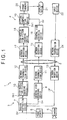
- Fig. 1 is a block diagram of a moving picture distribution system 1 practised as the first embodiment.
- a transmitting side 3 transmits a moving picture stream over a network 2 such as the Internet for reception by a receiving side 4.
- a camera 5 takes pictures of a desired object and outputs video data DV constituting moving pictures.
- a frame memory 6 holds the video data DV temporarily before output.
- a region extraction device 7 forwards the video data DV unmodified from the frame memory 6 to a general view encoding device 8.
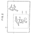
- the region extraction device 7 may then be notified of position information DP, as shown in Fig. 2, from a network reception device 13 regarding the video data DV destined for the general view encoding device 8.
- the region extraction device 7 establishes a partial picture region AR1 based on the position information DP and outputs video data DV1 constituting the partial region AR1 to a high-resolution picture encoding device 10.
- the position information DP is information which denotes the display position selected by a user on the receiving side 4 within the general view constituted by the video data DV.
- the position information DP is transmitted from the receiving side 4 in response to the user's operation.
- the region extraction device 7 establishes the partial region AR1 extending in the horizontal and perpendicular directions from a position designated by the position information DP as a center point of a picture portion, before outputting the video data DV1 constituting the partial region AR1 to the high-resolution picture encoding device 10.
- the region extraction device 7 keeps outputting to the high-resolution picture encoding device 10 the video data DV1 about the partial region AR1 for a predetermined period of time measured by an internal timer. When the predetermined time period has elapsed, the region extraction device 7 stops sending the video data DV1 to the high-resolution picture encoding device 10.
- the general view encoding device 8 compresses the video data DV from the region extraction device 7 at a relatively high data compression rate prior to output.
- the output data from the general view encoding device 8 are placed by a network transmission device 11 onto the network 2.
- the transmitting side 3 distributes all video data DV obtained from the camera 5 over the network 2 after having the data compressed at a relatively high data compression rate.
- the high-resolution picture encoding device 10 compresses the partial region video data DV1 from the region extraction device 7 prior to output. During the compression process, the high-resolution picture encoding device 10 compresses the video data DV1 at a lower data compression rate than the general view encoding device 8 for output. That is, the high-resolution picture encoding device 10 outputs encoded moving picture data at a higher resolution than the general view encoding device 8 outputting its moving picture stream.
- a network transmission device 12 places the output data from the high-resolution picture encoding device 10 onto the network 2. Based on the position information DP, the transmitting side 3 transmits the selected part of the video data DV from the camera 5 at a higher resolution than the rest of the video data DV.
- the network reception device 13 acquires the position information DP from the receiving side 4 and forwards the acquired information to the region extraction device 7. Accordingly, the region extraction device 7 in the moving picture distribution system 1 transmits the general view video data DV at the higher data compression rate while feeding the video data DV1 representing the partial picture region designated by the receiving side 4 at the higher resolution.
- a network reception device 15 receives the moving picture stream from the network transmission device 11 and forwards what is received to downstream devices.
- a general view decoding device 16 decodes the video data DV out of the moving picture stream coming from the network reception device 15, before outputting the decoded video data DV.
- Another network reception device 17 on the receiving side 4 receives the moving picture stream coming from the network transmission device 12 and forwards what is received to downstream devices.
- a high-resolution picture decoding device 18 decodes the video data DV1 out of the moving picture stream coming from the network reception device 17, before outputting the decoded video data DV1.
- a picture composition device 19 substitutes the video data DV1 from the high-resolution picture decoding device 18 for part of the video data DV from the general view decoding device 16 before outputting the composite video data to a frame memory 20.
- the frame memory 20 temporarily retains the output data from the picture composition device 19 before outputting the data to a display device 21.
- the display device 21 displays the data from the frame memory 20.
- An input device 22 is composed of two-dimensional coordinate inputting means such as a mouse.
- the input device 22 when operated by the user, moves a cursor on a display screen of the display device 21.
- the input device 22 when further operated by the user, outputs coordinates DP of a specific display position on the display device 21.
- the output coordinate information DP is sent by a network transmission device 24 over the network 2 to the transmitting side 3.
- the video data DV acquired by the camera 5 are input to the general view encoding device 8 for data compression into the moving picture stream.
- the moving picture stream is transmitted over the network 2 to the receiving side 4.
- the general view decoding device 16 decodes the original video data DV out of the received stream.
- the display device 21 displays moving pictures reflecting the data.
- the moving picture distribution system 1 thus allows moving pictures taken by the camera 5 to be viewed on the display device 21. Because the moving picture stream thus transmitted has been compressed by the general view encoding device 8 at a high data compression rate, the stream lacks detailed information and has the correspondingly lower picture quality than the original video data DV when displayed.
- the user operates the input device 22 to designate that part on the screen of the display device 21.
- the position information DP about the designated part is reported to the transmitting side 3 (Fig. 2).
- the report causes the transmitting side 3 to locate the partial picture region AR1.
- the video data DV1 constituting the region AR1 are output by the region extraction device 7 to the high-resolution encoding device 10.
- the encoding device 10 compresses the video data DV1 on the user-designated region at a lower data compression rate than the general view video data DV for the moving picture stream.
- the moving picture stream from the lower-rate compression is sent to and decoded by the receiving side 4.
- the high-resolution moving pictures substitute for part of the general view constituted by the video data DV.
- the first embodiment permits users to view a desired partial region of the picture at higher resolution than the remaining regions.
- the feature is particularly useful in applications such as the moving picture streaming service wherein only a user-designated specific portion of each picture is distributed at the reduced data compression rate to the user in question.
- different users can enjoy their preferred portions of the moving picture stream at the higher picture quality than the remaining picture portions.
- a target which a user wishes to view in detail may move out of the user-designated partial region AR1 as time elapses, since the target is constantly moving in the moving picture.
- the position information DP may be reported from the receiving side 4 together with time frame information.
- the transmitting side 3 transmits the high-resolution moving picture stream during that time frame and stops sending the stream once that time frame has elapsed. In this manner, the inventive moving picture distribution system 1 effectively averts wasteful transmission of the video data that are no longer desired.
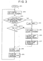
- Fig. 3 is a flowchart of steps performed by the transmitting side 3. Following the start of moving picture distribution in step SP1, the transmitting side 3 goes to step SP2. In step SP2, the transmitting side 3 causes the camera 5 to capture moving pictures to be transmitted. In step SP3, a check is made to see if position information DP is acquired by the network reception device 13. If the position information DP is judged acquired, that means a partial picture region needs to be extracted for higher-resolution transmission.
- step SP4 is reached in which a timer is set on the region extraction device 7.
- step SP5 the timer starts counting.
- step SP6 the position information DP is used as a basis for extracting video data DV1 representing a partial picture region AR1.
- step SP7 the extracted video data DV1 are encoded by the high-resolution picture encoding device 10.
- step SP8 general view video data DV corresponding to a whole picture are fed to the general view encoding device 8.
- step SP9 the video data DV are encoded. After transmitting two sets of moving picture stream to the receiving side 4, the transmitting side 3 goes back to step SP2 to process another picture.
- step SP10 a check is made to see if a predetermined period of time has elapsed on the timer started in step SP5 since the start of a high-resolution moving picture stream. If in step SP10 the predetermined time period is not judged to have elapsed, then step SP5 is reached. In this case, too, the high-resolution moving picture stream is transmitted.
- step SP10 If in step SP10 the predetermined time period is judged to have elapsed, the transmitting side 3 goes to step SP8.
- step SP8 only the general view moving picture stream is output by the general view encoding device 8 and the high-resolution moving picture stream is suppressed.
- the first embodiment of the above-described constitution outputs general view video data at a high data compression rate while transmitting a partial picture region at a high resolution in accordance with position information acquired from a transmission destination.
- a particular portion of each picture is thus designated by individual users for transmission at the reduced data compression rate (i.e., at high resolution) in the moving picture streaming service, user preferences are adequately addressed.
- Fig. 4 is a block diagram of a moving picture distribution system 31 practiced as the second embodiment of this invention.
- the moving picture distribution system 31 distributes moving pictures to a plurality of destinations.
- the component parts with their functionally identical or equivalent counterparts already indicated in the moving picture distribution system 1 of Fig. 1 are designated by like reference numerals, and their descriptions are omitted where redundant.
- a transmitting side 33 causes a general view encoding device 8 to transmit a moving picture stream commonly to receiving sides 4A and 4B which are transmission destinations. More specifically, the transmitting side 33 first directs video data DV from a frame memory 6 through a region extraction device 37 to the general view encoding device 8. The encoding device 8 encodes the video data DV into a picture stream at a high data compression rate and transmits the encoded stream to the receiving sides 4A and 4B via a network transmission device 11.
- the transmitting side 33 allows network reception devices 13A and 13B to acquire position information DPA and DPB respectively from the receiving sides. Given the two sets of position information, the region extraction device 37 establishes partial picture regions correspondingly and outputs video data DV1A and DV1B representing the established picture regions.
- the video data DV1A and DV1B are encoded respectively by high-resolution picture encoding devices 10A and 10B generating high-resolution moving picture streams destined for the receiving sides.
- the two streams are output to the relevant receiving sides 4A and 4B.
- the receiving sides 4A and 4B commonly receive the moving picture stream from the general view encoding device 8 and decode the video data DV therefrom. Furthermore, the receiving sides 4A and 4B receive the individually transmitted high-resolution moving picture streams and decode the image data DV1A and DV1B therefrom.
- the general view moving picture stream and each of the high-resolution moving picture streams are composed by picture composition devices 19A and 19B.
- the composed video data are reproduced by display devices 21A and 21B. Viewing reproduced pictures on the display devices 21A and 21B, users may operate input devices 22A and 22B to send position information DPA and DPB to the transmitting side 33.
- the second embodiment shown in Fig. 4 sends to each destination the general view video data at the high data compression rate while feeding partial picture region data at the reduced data compression rate for high-resolution transmission based on the position information acquired from the destination in question.
- the moving picture stream encoded at the high data compression rate is output commonly to a plurality of destinations.
- position information is acquired from each of the multiple destinations so that a desired partial region of each picture is designated accordingly for each destination.
- Video data representing the partial region are then encoded at high resolution before being transmitted to the respective destinations.
- the above embodiments were described as setting the partial picture region for high-resolution transmission in a uniquely defined fashion based on the position information acquired from the transmission destination.
- the position information acquired from the destination may be subjected to a peripheral feature extraction method or like process.
- the actual region for high-resolution transmission may be established accordingly.
- Other diverse techniques may also be resorted to in establishing the partial picture region to be transmitted at high resolution.
- An alternative embodiment of the invention may be arranged to gradually end the high-resolution transmission by letting the reduced data compression rate return progressively to the high data compression rate for the general view transmission. This prevents an abrupt, awkward change of picture quality in the moving pictures being displayed on the receiving side.
- the frame memory 6 may be incorporated into the region extraction device.
- the general view encoding device and high-resolution picture encoding device are furnished separately.
- the two encoding devices may be designed to share part of their components.
- transmitting and receiving sides of each embodiment of the invention above were described as implemented on a hardware basis, this is not limitative of the invention. Alternatively, part or all of the transmitting and receiving sides may be implemented by software.
- general view video data are transmitted at a high data compression rate while a specific region of each picture defined as per the position information acquired from a transmission destination is transmitted at high resolution, i.e., at a reduced data compression rate.
Landscapes
- Engineering & Computer Science (AREA)
- Multimedia (AREA)
- Signal Processing (AREA)
- Two-Way Televisions, Distribution Of Moving Picture Or The Like (AREA)
- Compression Or Coding Systems Of Tv Signals (AREA)
Description
- The present invention relates to a picture transmission method, a picture transmission method program, a storage medium which stores the picture I transmission method program, and a picture transmission apparatus. More particularly, the invention relates to techniques for distributing a moving picture stream over a network. According to the invention, picture data as a whole are first transmitted when compressed at a high compression rate. Based on position information acquired from a given transmission destination, part of the I picture data representing a partial picture region is transmitted at a higher resolution than the remaining regions. That is, a user-designated partial region of each picture is compressed at a reduced data compression rate for a moving picture streaming service, so that users may watch desired portions of the streaming moving pictures reproduced at a higher resolution.
- Conventionally, moving picture streams are distributed over a network such as the Internet using a real-time compression and transmission system such as MPEG4 (Moving Picture Experts Group Phase 4).
- MPEG4 represents techniques for efficiently compressing moving picture data through the effective use of correlations between continuous pictures. Where moving picture data streams are distributed using MPEG4, the data compression rate is varied depending on the current amount of encoded data so that the data may be transmitted at a bit rate commensurate with the capacity of communication lines being used.
- With such a real-time compression and transmission system in use, higher data compression rates necessarily increase the amount of the data dropped from the original moving picture data and a transmission destination may not be able to reproduce clear pictures (i.e. pictures of high qualities). On the other hand, reduced data compression rates eventually make it impossible to transmit moving picture data over communication lines that have limited capacities.
- One proposed solution (ROI) to the above problem involves reducing the data compression rate for only a specific region of each moving picture. In other words, only that part of each picture which users are presumably desirous of watching at higher quality is transmitted at higher resolution while the remaining portions which users do not need in detailed picture, such as background, are left to have lower quality. The conventional solution is supposed efficiently to transmit moving picture data over communication lines subject to limited capacities.
- One disadvantage of the solution above is that the specific region of each picture selected for the high-resolution transmission may differ from the one that is desired by a user. Different users have different preferences. In a football game broadcast, for example, some users may look for a detailed picture of a particular player on defense side while other users may prefer watching a high-resolution image of another player on offence side.
- Transmitting picture portions that are not desired by a user at high resolution may be wasteful. Under the conventional scheme, a number of users may miss high-quality images of their preference.
- As outlined above, if only a fixed region of each picture is compressed at areduced data compression rate for higher-quality distribution over the network by a moving picture streaming service, some users are satisfied but others are not. The conventional method has failed to address the diverse user preferences where pictures are transmitted on a partial-region enhanced-quality basis.
- From WO 01 50754 A which is to be regarded as relevant pursuant to Art. 54(3) and (4) EPC it is known for a picture transmission to encode moving picture data and to transmit the encoded data wherein firstly said moving picture data are encoded into a moving picture stream for transmission at a predetermined data transfer rate and encoding secondly, based on position information acquired from a transmission destination, a part of said moving picture data which constitutes a partial picture region for transmission at a higher resolution than said first encoding step. However, the first encoded picture stream is transmitted over a first transmitting channel of a certain characteristic whereas the second encoded part picture stream is transmitted over a second very distinct unidirectional transmitting channel.
- In US 6,178,204 B1 and US 6,078,349 A there are disclosed methods for improving the display resolution of a video image in a region selected by a user. The video image in which a selected region has higher resolution than the remaining image regions is transmitted such that high and low resolution moving picture data are always received together.
- It is the object of the present invention to provide a picture transmission method, a picture transmission method program, a storage medium which stores the picture transmission method program, and a picture transmission apparatus for adequately addressing user preferences so that a user designated specific region of each picture is compressed at a lower data compression rate for higher resolution distribution through a moving picture streaming service.
- The solution according to the present invention is set forth in the independent claims.
- Advantageous features are set forth in the dependent claims.
- Other objects, features and advantages of the invention will become more apparent upon a reading of the following description and appended drawings.
-
- Fig. 1 is a block diagram of a moving picture distribution system practised as a first embodiment not belonging to the present invention.
- Fig. 2 is a plan view showing relations between the overall view of a picture and a specific region of that picture having a higher resolution than the rest of the picture as displayed by the system of Fig. 1;
- Fig. 3 is a flowchart of steps performed by the transmitting side in the moving picture distribution system of Fig. 1; and
- Fig. 4 is a block diagram of a moving picture distribution system practised as a second embodiment of the present invention.
- Before describing an embodiment of the present invention, called second embodiment, there will now be described in detail in embodiment not belonging to the present invention, called first embodiment, however helping the understanding thereof.
- Fig. 1 is a block diagram of a moving picture distribution system 1 practised as the first embodiment. In the moving picture distribution system 1, a transmitting
side 3 transmits a moving picture stream over anetwork 2 such as the Internet for reception by a receivingside 4. - On the transmitting
side 3, acamera 5 takes pictures of a desired object and outputs video data DV constituting moving pictures. Aframe memory 6 holds the video data DV temporarily before output. - A region extraction device 7 forwards the video data DV unmodified from the
frame memory 6 to a generalview encoding device 8. The region extraction device 7 may then be notified of position information DP, as shown in Fig. 2, from anetwork reception device 13 regarding the video data DV destined for the generalview encoding device 8. In that case, the region extraction device 7 establishes a partial picture region AR1 based on the position information DP and outputs video data DV1 constituting the partial region AR1 to a high-resolutionpicture encoding device 10. - The position information DP is information which denotes the display position selected by a user on the receiving
side 4 within the general view constituted by the video data DV. When thus designated, the position information DP is transmitted from the receivingside 4 in response to the user's operation. Given the position information DP, the region extraction device 7 establishes the partial region AR1 extending in the horizontal and perpendicular directions from a position designated by the position information DP as a center point of a picture portion, before outputting the video data DV1 constituting the partial region AR1 to the high-resolutionpicture encoding device 10. - When notified of the position information DP from the
network reception device 13, the region extraction device 7 keeps outputting to the high-resolutionpicture encoding device 10 the video data DV1 about the partial region AR1 for a predetermined period of time measured by an internal timer. When the predetermined time period has elapsed, the region extraction device 7 stops sending the video data DV1 to the high-resolutionpicture encoding device 10. - Based illustratively on MPEG4, the general
view encoding device 8 compresses the video data DV from the region extraction device 7 at a relatively high data compression rate prior to output. The output data from the generalview encoding device 8 are placed by anetwork transmission device 11 onto thenetwork 2. In this manner, the transmittingside 3 distributes all video data DV obtained from thecamera 5 over thenetwork 2 after having the data compressed at a relatively high data compression rate. - Using the same predictive coding scheme as the general
view encoding device 8, the high-resolutionpicture encoding device 10 compresses the partial region video data DV1 from the region extraction device 7 prior to output. During the compression process, the high-resolutionpicture encoding device 10 compresses the video data DV1 at a lower data compression rate than the generalview encoding device 8 for output. That is, the high-resolutionpicture encoding device 10 outputs encoded moving picture data at a higher resolution than the generalview encoding device 8 outputting its moving picture stream. - A
network transmission device 12 places the output data from the high-resolutionpicture encoding device 10 onto thenetwork 2. Based on the position information DP, the transmittingside 3 transmits the selected part of the video data DV from thecamera 5 at a higher resolution than the rest of the video data DV. - The
network reception device 13 acquires the position information DP from the receivingside 4 and forwards the acquired information to the region extraction device 7. Accordingly, the region extraction device 7 in the moving picture distribution system 1 transmits the general view video data DV at the higher data compression rate while feeding the video data DV1 representing the partial picture region designated by the receivingside 4 at the higher resolution. - On the
receiving side 4, anetwork reception device 15 receives the moving picture stream from thenetwork transmission device 11 and forwards what is received to downstream devices. A generalview decoding device 16 decodes the video data DV out of the moving picture stream coming from thenetwork reception device 15, before outputting the decoded video data DV. - Another
network reception device 17 on thereceiving side 4 receives the moving picture stream coming from thenetwork transmission device 12 and forwards what is received to downstream devices. A high-resolutionpicture decoding device 18 decodes the video data DV1 out of the moving picture stream coming from thenetwork reception device 17, before outputting the decoded video data DV1. - A
picture composition device 19 substitutes the video data DV1 from the high-resolutionpicture decoding device 18 for part of the video data DV from the generalview decoding device 16 before outputting the composite video data to aframe memory 20. Theframe memory 20 temporarily retains the output data from thepicture composition device 19 before outputting the data to adisplay device 21. Thedisplay device 21 displays the data from theframe memory 20. - An
input device 22 is composed of two-dimensional coordinate inputting means such as a mouse. Theinput device 22, when operated by the user, moves a cursor on a display screen of thedisplay device 21. Theinput device 22, when further operated by the user, outputs coordinates DP of a specific display position on thedisplay device 21. The output coordinate information DP is sent by anetwork transmission device 24 over thenetwork 2 to the transmittingside 3. - In the moving picture distribution system 1 of the above constitution (Fig. 1), the video data DV acquired by the
camera 5 are input to the generalview encoding device 8 for data compression into the moving picture stream. After the compression, the moving picture stream is transmitted over thenetwork 2 to the receivingside 4. I On the receivingside 4, the generalview decoding device 16 decodes the original video data DV out of the received stream. Given the decoded video data DV, thedisplay device 21 displays moving pictures reflecting the data. - The moving picture distribution system 1 thus allows moving pictures taken by the
camera 5 to be viewed on thedisplay device 21. Because the moving picture stream thus transmitted has been compressed by the generalview encoding device 8 at a high data compression rate, the stream lacks detailed information and has the correspondingly lower picture quality than the original video data DV when displayed. - If a user wants a specific part of the general view to be displayed in more detail, the user operates the
input device 22 to designate that part on the screen of thedisplay device 21. In turn, the position information DP about the designated part is reported to the transmitting side 3 (Fig. 2). The report causes the transmittingside 3 to locate the partial picture region AR1. The video data DV1 constituting the region AR1 are output by the region extraction device 7 to the high-resolution encoding device 10. Theencoding device 10 compresses the video data DV1 on the user-designated region at a lower data compression rate than the general view video data DV for the moving picture stream. The moving picture stream from the lower-rate compression is sent to and decoded by the receivingside 4. The high-resolution moving pictures substitute for part of the general view constituted by the video data DV. - As described, the first embodiment permits users to view a desired partial region of the picture at higher resolution than the remaining regions. The feature is particularly useful in applications such as the moving picture streaming service wherein only a user-designated specific portion of each picture is distributed at the reduced data compression rate to the user in question. Thus different users can enjoy their preferred portions of the moving picture stream at the higher picture quality than the remaining picture portions.
- In such a moving picture bit streaming application, it is possible that a target which a user wishes to view in detail may move out of the user-designated partial region AR1 as time elapses, since the target is constantly moving in the moving picture. When that eventuality is taken into account, the position information DP may be reported from the receiving
side 4 together with time frame information. In that case, the transmittingside 3 transmits the high-resolution moving picture stream during that time frame and stops sending the stream once that time frame has elapsed. In this manner, the inventive moving picture distribution system 1 effectively averts wasteful transmission of the video data that are no longer desired. - Fig. 3 is a flowchart of steps performed by the transmitting
side 3. Following the start of moving picture distribution in step SP1, the transmittingside 3 goes to step SP2. In step SP2, the transmittingside 3 causes thecamera 5 to capture moving pictures to be transmitted. In step SP3, a check is made to see if position information DP is acquired by thenetwork reception device 13. If the position information DP is judged acquired, that means a partial picture region needs to be extracted for higher-resolution transmission. - If in step SP3 the position information DP is judged acquired, step SP4 is reached in which a timer is set on the region extraction device 7. In step SP5, the timer starts counting. In step SP6, the position information DP is used as a basis for extracting video data DV1 representing a partial picture region AR1. In step SP7, the extracted video data DV1 are encoded by the high-resolution
picture encoding device 10. In step SP8, general view video data DV corresponding to a whole picture are fed to the generalview encoding device 8. In step SP9, the video data DV are encoded. After transmitting two sets of moving picture stream to the receivingside 4, the transmittingside 3 goes back to step SP2 to process another picture. - If in step SP3 the position information DP is not judged acquired, the transmitting
side 3 goes to step SP10. In step SP10, a check is made to see if a predetermined period of time has elapsed on the timer started in step SP5 since the start of a high-resolution moving picture stream. If in step SP10 the predetermined time period is not judged to have elapsed, then step SP5 is reached. In this case, too, the high-resolution moving picture stream is transmitted. - If in step SP10 the predetermined time period is judged to have elapsed, the transmitting
side 3 goes to step SP8. In step SP8, only the general view moving picture stream is output by the generalview encoding device 8 and the high-resolution moving picture stream is suppressed. - The first embodiment of the above-described constitution outputs general view video data at a high data compression rate while transmitting a partial picture region at a high resolution in accordance with position information acquired from a transmission destination. When a particular portion of each picture is thus designated by individual users for transmission at the reduced data compression rate (i.e., at high resolution) in the moving picture streaming service, user preferences are adequately addressed.
- Fig. 4 is a block diagram of a moving
picture distribution system 31 practiced as the second embodiment of this invention. The movingpicture distribution system 31 distributes moving pictures to a plurality of destinations. In the movingpicture distribution system 31 of Fig. 4, the component parts with their functionally identical or equivalent counterparts already indicated in the moving picture distribution system 1 of Fig. 1 are designated by like reference numerals, and their descriptions are omitted where redundant. - In the moving
picture distribution system 31, a transmittingside 33 causes a generalview encoding device 8 to transmit a moving picture stream commonly to receivingsides side 33 first directs video data DV from aframe memory 6 through aregion extraction device 37 to the generalview encoding device 8. Theencoding device 8 encodes the video data DV into a picture stream at a high data compression rate and transmits the encoded stream to the receivingsides network transmission device 11. - The transmitting
side 33 allowsnetwork reception devices region extraction device 37 establishes partial picture regions correspondingly and outputs video data DV1A and DV1B representing the established picture regions. - On the transmitting
side 33, the video data DV1A and DV1B are encoded respectively by high-resolutionpicture encoding devices 10A and 10B generating high-resolution moving picture streams destined for the receiving sides. The two streams are output to therelevant receiving sides - The receiving
sides view encoding device 8 and decode the video data DV therefrom. Furthermore, the receivingsides picture composition devices display devices display devices input devices 22A and 22B to send position information DPA and DPB to the transmittingside 33. - In transmitting moving pictures to a plurality of destinations, the second embodiment shown in Fig. 4 sends to each destination the general view video data at the high data compression rate while feeding partial picture region data at the reduced data compression rate for high-resolution transmission based on the position information acquired from the destination in question. With any particular portion of each picture thus designated by users of different destinations for transmission at the reduced data compression rate in the moving picture streaming service, user preferences are adequately addressed.
- The moving picture stream encoded at the high data compression rate is output commonly to a plurality of destinations. In turn, position information is acquired from each of the multiple destinations so that a desired partial region of each picture is designated accordingly for each destination. Video data representing the partial region are then encoded at high resolution before being transmitted to the respective destinations. This setup requires less transmission line occupancy than conventional arrangements wherein moving pictures are individually prepared and transmitted to a plurality of destinations. Reductions in line occupancy translate into higher levels of efficiency at which moving pictures are transmitted.
- The embodiments above were shown acquiring from a transmission destination the center coordinates of a partial picture region desired by the user in order to establish the picture region to be transmitted at high resolution. However, this is not limitative of the invention. An alternative embodiment of the invention may be arranged directly to accept the user's command for establishing the partial picture region.
- The above embodiments were described as setting the partial picture region for high-resolution transmission in a uniquely defined fashion based on the position information acquired from the transmission destination. Alternatively, the position information acquired from the destination may be subjected to a peripheral feature extraction method or like process. When the nature or character of the target desired by the user is determined by such a method, the actual region for high-resolution transmission may be established accordingly. Other diverse techniques may also be resorted to in establishing the partial picture region to be transmitted at high resolution.
- The above-described embodiments of the invention were shown transmitting a desired partial picture region for a predetermined period of time once the region is established for high-resolution transmission in accordance with the position information acquired from the transmission destination. Alternatively, a motion tracking technique or like process may be used to track the target in motion. This allows the partial picture region for high-resolution transmission to shift in position or be enlarged or contracted in area while the target is moving.
- The embodiments above were shown stopping the high-resolution transmission immediately upon elapse of a predetermined period of time. However, this is not limitative of the invention. An alternative embodiment of the invention may be arranged to gradually end the high-resolution transmission by letting the reduced data compression rate return progressively to the high data compression rate for the general view transmission. This prevents an abrupt, awkward change of picture quality in the moving pictures being displayed on the receiving side.
- The above embodiments were described as having the region extraction device and the
frame memory 6 furnished separately. Alternatively, theframe memory 6 may be incorporated into the region extraction device. - In the above-described embodiments, the general view encoding device and high-resolution picture encoding device are furnished separately. In an alternative embodiment of the invention, the two encoding devices may be designed to share part of their components.
- Whereas the embodiments above were shown adopting MPEG4 or like encoding methods for compressing general view video data for low-resolution general view transmission while encoding partial picture region data for high-resolution moving picture transmission, this is not limitative of the invention. Alternatively, many other data compression methods may be adopted for data compression and transmission.
- Although the transmitting and receiving sides of each embodiment of the invention above were described as implemented on a hardware basis, this is not limitative of the invention. Alternatively, part or all of the transmitting and receiving sides may be implemented by software.
- As described and according to the invention, general view video data are transmitted at a high data compression rate while a specific region of each picture defined as per the position information acquired from a transmission destination is transmitted at high resolution, i.e., at a reduced data compression rate. With any particular portion of each picture designated by individual users for high-resolution transmission at the reduced data compression rate in the moving picture streaming service, user preferences are adequately addressed.
Claims (8)
- A picture transmission method for encoding moving picture data and transmitting the encoded data, the method comprising the steps of:encoding firstly (8) said moving picture data into a moving picture stream for transmission over a network (2) at a predetermined data transfer rate; andencoding secondly (7, 10), based on position information (DP), a part of said moving picture data which constitutes a partial picture region (AR1) for transmission over said network (2) at a higher resolution than the moving picture data encoded in said first encoding step; whereinsaid position information (DP) is acquired respectively from receiving sides (4A, 4B);said moving picture data encoded by said first encoding step are output to said receiving sides (4A, 4B) commonly; andsaid moving picture data encoded by said second encoding step are output to said receiving sides individually.
- A picture transmission method according to claim 1, wherein
when a predetermined time period has elapsed (SP4, SP5, SP10) after the position information (DP) is acquired (SP3) from a receiving side (4A, 4B), the transmission over said network (2) of the high resolution moving picture data encoded in said second encoding step (7, 10) to said receiving side (4A, 4B) is stopped. - A picture transmission method program for encoding moving picture data and transmitting the encoded data, the program comprising the steps of:encoding firstly (8) said moving picture data into a moving picture stream for transmission over a network (2) at a predetermined data transfer rate; andencoding secondly (7, 10), based on position information (DP), a part of said moving picture data which constitutes a partial picture region (AR1) for transmission over said network (2) at a higher resolution than the moving picture data encoded in said first encoding step; whereinsaid position information (DP) is acquired respectively from receiving sides (4A, 4B);said moving picture data encoded by said first encoding step are output to said receiving sides (4A, 4B) commonly; andsaid moving picture data encoded by said second encoding step are output to said receiving sides individually.
- A picture transmission method program according to claim 3, wherein
when a predetermined time period has elapsed (SP4, SP5, SP10) after the position information (DP) is acquired (SP3) from a receiving side (4A, 4B), the transmission over said network (2) of the high resolution moving picture data encoded in said second encoding step (7, 10) to said receiving side (4A, 4B) is stopped. - A storage medium which stores a picture transmission method program for encoding moving picture data and transmitting the encoded data, the program comprising the steps of:encoding firstly (8) said moving picture data into a moving picture stream for transmission over a network (2) at a predetermined data transfer rate; andencoding secondly (7, 10), based on position information (DP), a part of said moving picture data which constitutes a partial picture region (AR1) for transmission over said network (2) at a higher resolution than the moving picture data encoded in said first encoding step; whereinsaid position information (DP) is acquired respectively from receiving sides (4A, 4B);said moving picture data encoded by said first encoding step are output to said receiving sides (4A, 4B) commonly; andsaid moving picture data encoded by said second encoding step are output to said receiving sides individually.
- A storage medium according to claim 5, wherein
when a predetermined time period has elapsed (SP4, SP5, SP10) after the position information (DP) is acquired (SP3) from a receiving side (4A, 4B), the transmission over said network (2) of the high resolution moving picture data encoded in said second encoding step (7, 10) to said receiving side (4A, 4B) is stopped. - A picture transmission apparatus for encoding moving picture data and transmitting the encoded data, the apparatus comprising:first encoding means (8) adapted for encoding said moving picture data into a moving picture stream for transmission over a network (2) at a predetermined data transfer rate; andsecond encoding means (7, 10) adapted for, based on position information (DP), encoding a part of said moving picture data which constitutes a partial picture region (AR1) for transmission over said network (2) at a higher resolution than the moving picture data encoded by said first encoding means, whereinsaid apparatus is adapted to acquire said position information (DP) respectively from receiving sides (4A, 4B); to output said moving picture data encoded by said first encoding step to said receiving sides (4A, 4B) commonly; and to output said moving picture data encoded by said second encoding step to said receiving sides individually.
- A picture transmission apparatus according to claim 7, wherein
the picture transmission apparatus is adapted to stop the transmission over said network (2) of the high resolution moving picture data encoded by said second encoding means (7, 10) to a receiving side (4A, 4B), when a predetermined time period has elapsed (SP4, SP5, SP10) after the position information (DP) is acquired (SP3) from said receiving side (4A, 4B).
Applications Claiming Priority (2)
| Application Number | Priority Date | Filing Date | Title |
|---|---|---|---|
| JP2001133770A JP2002330440A (en) | 2001-05-01 | 2001-05-01 | Image transmission method, program for the image transmission method, recording medium for recording the program for the image transmission method, and image transmitter |
| JP2001133770 | 2001-05-01 |
Publications (3)
| Publication Number | Publication Date |
|---|---|
| EP1259080A2 EP1259080A2 (en) | 2002-11-20 |
| EP1259080A3 EP1259080A3 (en) | 2003-11-26 |
| EP1259080B1 true EP1259080B1 (en) | 2006-09-13 |
Family
ID=18981570
Family Applications (1)
| Application Number | Title | Priority Date | Filing Date |
|---|---|---|---|
| EP20020009681 Expired - Fee Related EP1259080B1 (en) | 2001-05-01 | 2002-04-29 | Picture transmission method, picture transmission method program, storage medium which stores picture transmission method program, and picture transmission apparatus |
Country Status (4)
| Country | Link |
|---|---|
| US (2) | US7529298B2 (en) |
| EP (1) | EP1259080B1 (en) |
| JP (1) | JP2002330440A (en) |
| DE (1) | DE60214622T2 (en) |
Families Citing this family (25)
| Publication number | Priority date | Publication date | Assignee | Title |
|---|---|---|---|---|
| JP2002330440A (en) * | 2001-05-01 | 2002-11-15 | Sony Corp | Image transmission method, program for the image transmission method, recording medium for recording the program for the image transmission method, and image transmitter |
| NO321642B1 (en) * | 2004-09-27 | 2006-06-12 | Tandberg Telecom As | Procedure for encoding image sections |
| US8179961B2 (en) * | 2006-07-17 | 2012-05-15 | Thomson Licensing | Method and apparatus for adapting a default encoding of a digital video signal during a scene change period |
| KR101295158B1 (en) * | 2007-02-20 | 2013-08-09 | 세종대학교산학협력단 | Image codec system for supporting spatial random access and image encoding/decoding equipment and method thereof |
| JP2010525746A (en) | 2007-04-25 | 2010-07-22 | チャウム,デイビッド | Video copy protection system with interaction and compression |
| WO2009063637A1 (en) * | 2007-11-15 | 2009-05-22 | Sanyo Electric Co., Ltd. | Image transmission method and image transmitter |
| US8456380B2 (en) * | 2008-05-15 | 2013-06-04 | International Business Machines Corporation | Processing computer graphics generated by a remote computer for streaming to a client computer |
| US8385404B2 (en) | 2008-09-11 | 2013-02-26 | Google Inc. | System and method for video encoding using constructed reference frame |
| JP5089658B2 (en) * | 2009-07-16 | 2012-12-05 | 株式会社Gnzo | Transmitting apparatus and transmitting method |
| JP5664289B2 (en) * | 2011-01-31 | 2015-02-04 | 富士通株式会社 | Information processing apparatus, image transmission program, and image display method |
| US9154799B2 (en) | 2011-04-07 | 2015-10-06 | Google Inc. | Encoding and decoding motion via image segmentation |
| US8638854B1 (en) | 2011-04-07 | 2014-01-28 | Google Inc. | Apparatus and method for creating an alternate reference frame for video compression using maximal differences |
| US11039109B2 (en) | 2011-08-05 | 2021-06-15 | Fox Sports Productions, Llc | System and method for adjusting an image for a vehicle mounted camera |
| JP2014529930A (en) | 2011-08-05 | 2014-11-13 | フォックス スポーツ プロダクションズ,インコーポレイティッド | Selective capture and display of a portion of a native image |
| US9609341B1 (en) | 2012-04-23 | 2017-03-28 | Google Inc. | Video data encoding and decoding using reference picture lists |
| EP2842337B1 (en) | 2012-04-23 | 2019-03-13 | Google LLC | Managing multi-reference picture buffers for video data coding |
| EP2765781A1 (en) * | 2013-02-07 | 2014-08-13 | Thomson Licensing | Method for providing targetable content in images of a video sequence and corresponding device |
| JP2014183353A (en) * | 2013-03-18 | 2014-09-29 | Sony Corp | Video processing device, video reproducing device, video processing method, video reproduction method, and video processing system |
| JP2014192844A (en) * | 2013-03-28 | 2014-10-06 | Hitachi Kokusai Electric Inc | Video distribution system, video distribution method, video distribution device and video display device |
| US9756331B1 (en) | 2013-06-17 | 2017-09-05 | Google Inc. | Advance coded reference prediction |
| WO2016046860A1 (en) * | 2014-09-22 | 2016-03-31 | 三菱電機株式会社 | Image encoding/transmitting apparatus, image decoding apparatus, image encoding/transmitting method, and image decoding method |
| US11758238B2 (en) | 2014-12-13 | 2023-09-12 | Fox Sports Productions, Llc | Systems and methods for displaying wind characteristics and effects within a broadcast |
| US11159854B2 (en) | 2014-12-13 | 2021-10-26 | Fox Sports Productions, Llc | Systems and methods for tracking and tagging objects within a broadcast |
| US9288545B2 (en) | 2014-12-13 | 2016-03-15 | Fox Sports Productions, Inc. | Systems and methods for tracking and tagging objects within a broadcast |
| EP3113159A1 (en) | 2015-06-30 | 2017-01-04 | Thomson Licensing | Method and device for processing a part of an immersive video content according to the position of reference parts |
Family Cites Families (11)
| Publication number | Priority date | Publication date | Assignee | Title |
|---|---|---|---|---|
| JPH07288806A (en) * | 1994-04-20 | 1995-10-31 | Hitachi Ltd | Moving image communication system |
| US6078349A (en) * | 1995-06-07 | 2000-06-20 | Compaq Computer Corporation | Process and system for increasing the display resolution of a point-to-point video transmission relative to the actual amount of video data sent |
| IL117133A (en) * | 1996-02-14 | 1999-07-14 | Olivr Corp Ltd | Method and system for providing on-line virtual reality movies |
| JPH09261522A (en) * | 1996-03-27 | 1997-10-03 | Nippon Telegr & Teleph Corp <Ntt> | Video image distribution method and system to obtain variable area |
| DE59803369D1 (en) * | 1997-10-28 | 2002-04-18 | Siemens Ag | METHOD AND DEVICE FOR PROCESSING A DIGITIZED IMAGE |
| US6178204B1 (en) * | 1998-03-30 | 2001-01-23 | Intel Corporation | Adaptive control of video encoder's bit allocation based on user-selected region-of-interest indication feedback from video decoder |
| US6018359A (en) * | 1998-04-24 | 2000-01-25 | Massachusetts Institute Of Technology | System and method for multicast video-on-demand delivery system |
| US6496607B1 (en) * | 1998-06-26 | 2002-12-17 | Sarnoff Corporation | Method and apparatus for region-based allocation of processing resources and control of input image formation |
| US6476873B1 (en) * | 1998-10-23 | 2002-11-05 | Vtel Corporation | Enhancement of a selectable region of video |
| IL148431A0 (en) * | 1999-12-30 | 2002-09-12 | Swisscom Mobile Ag | Method for the transmission of image data |
| JP2002330440A (en) * | 2001-05-01 | 2002-11-15 | Sony Corp | Image transmission method, program for the image transmission method, recording medium for recording the program for the image transmission method, and image transmitter |
-
2001
- 2001-05-01 JP JP2001133770A patent/JP2002330440A/en active Pending
-
2002
- 2002-04-29 EP EP20020009681 patent/EP1259080B1/en not_active Expired - Fee Related
- 2002-04-29 DE DE2002614622 patent/DE60214622T2/en not_active Expired - Lifetime
- 2002-04-29 US US10/133,420 patent/US7529298B2/en not_active Expired - Fee Related
-
2009
- 2009-01-09 US US12/350,993 patent/US20090122859A1/en not_active Abandoned
Also Published As
| Publication number | Publication date |
|---|---|
| EP1259080A3 (en) | 2003-11-26 |
| US7529298B2 (en) | 2009-05-05 |
| DE60214622D1 (en) | 2006-10-26 |
| EP1259080A2 (en) | 2002-11-20 |
| JP2002330440A (en) | 2002-11-15 |
| US20020168006A1 (en) | 2002-11-14 |
| US20090122859A1 (en) | 2009-05-14 |
| DE60214622T2 (en) | 2007-09-13 |
Similar Documents
| Publication | Publication Date | Title |
|---|---|---|
| EP1259080B1 (en) | Picture transmission method, picture transmission method program, storage medium which stores picture transmission method program, and picture transmission apparatus | |
| JP5852157B2 (en) | Improved view layout management in scalable video and audio communication systems | |
| JP4585479B2 (en) | Server apparatus and video distribution method | |
| US6139197A (en) | Method and system automatically forwarding snapshots created from a compressed digital video stream | |
| CN101002471B (en) | Method and apparatus to encode image, and method and apparatus to decode image data | |
| CN101588488B (en) | Multiple-position streaming media broadcasting method and system | |
| US10623816B2 (en) | Method and apparatus for extracting video from high resolution video | |
| US20130111051A1 (en) | Dynamic Encoding of Multiple Video Image Streams to a Single Video Stream Based on User Input | |
| WO2001089221A1 (en) | Multiple camera video system which displays selected images | |
| CN1280744A (en) | Encoding system and method for scrolling encoded MPEG stills in an interactive television application | |
| JPH07274149A (en) | Video communication system, decoder circuit, video display system, encoder circuit and video data receiving method | |
| JP2011024018A (en) | Transmitting apparatus, receiving apparatus, transmitting method, receiving method, and transmission system | |
| KR101528863B1 (en) | Method of synchronizing tiled image in a streaming service providing system of panoramic image | |
| WO1998006222A1 (en) | Picture and sound decoding device, picture and sound encoding device, and information transmission system | |
| JP2008199677A (en) | Video distribution system | |
| KR20120133006A (en) | System and method for providing a service to streaming IPTV panorama image | |
| JP4148673B2 (en) | Video distribution system | |
| Mavlankar et al. | Video streaming with interactive pan/tilt/zoom | |
| JP4305752B2 (en) | VIDEO DISTRIBUTION SYSTEM, VIDEO DISTRIBUTION DEVICE, VIDEO DISTRIBUTION METHOD, AND VIDEO DISTRIBUTION PROGRAM | |
| US20200267199A1 (en) | Method and system for transmitting video | |
| JP2009212821A (en) | Content distribution device, reception device, content distribution method, and reception method | |
| JP2004040351A (en) | Image distribution system and image distribution reproducing system | |
| JP5940999B2 (en) | VIDEO REPRODUCTION DEVICE, VIDEO DISTRIBUTION DEVICE, VIDEO REPRODUCTION METHOD, VIDEO DISTRIBUTION METHOD, AND PROGRAM | |
| CN112954394A (en) | High-definition video encoding and decoding playing method, device, equipment and medium | |
| JP7296219B2 (en) | Receiving device, transmitting device, and program |
Legal Events
| Date | Code | Title | Description |
|---|---|---|---|
| PUAI | Public reference made under article 153(3) epc to a published international application that has entered the european phase |
Free format text: ORIGINAL CODE: 0009012 |
|
| AK | Designated contracting states |
Kind code of ref document: A2 Designated state(s): AT BE CH CY DE DK ES FI FR GB GR IE IT LI LU MC NL PT SE TR |
|
| AX | Request for extension of the european patent |
Free format text: AL;LT;LV;MK;RO;SI |
|
| PUAL | Search report despatched |
Free format text: ORIGINAL CODE: 0009013 |
|
| AK | Designated contracting states |
Kind code of ref document: A3 Designated state(s): AT BE CH CY DE DK ES FI FR GB GR IE IT LI LU MC NL PT SE TR |
|
| AX | Request for extension of the european patent |
Extension state: AL LT LV MK RO SI |
|
| RIC1 | Information provided on ipc code assigned before grant |
Ipc: 7H 04N 7/24 B Ipc: 7H 04N 7/26 A |
|
| 17P | Request for examination filed |
Effective date: 20040514 |
|
| AKX | Designation fees paid |
Designated state(s): DE FR GB |
|
| 17Q | First examination report despatched |
Effective date: 20040720 |
|
| GRAP | Despatch of communication of intention to grant a patent |
Free format text: ORIGINAL CODE: EPIDOSNIGR1 |
|
| GRAS | Grant fee paid |
Free format text: ORIGINAL CODE: EPIDOSNIGR3 |
|
| GRAA | (expected) grant |
Free format text: ORIGINAL CODE: 0009210 |
|
| AK | Designated contracting states |
Kind code of ref document: B1 Designated state(s): DE FR GB |
|
| REG | Reference to a national code |
Ref country code: GB Ref legal event code: FG4D |
|
| REF | Corresponds to: |
Ref document number: 60214622 Country of ref document: DE Date of ref document: 20061026 Kind code of ref document: P |
|
| ET | Fr: translation filed | ||
| PLBE | No opposition filed within time limit |
Free format text: ORIGINAL CODE: 0009261 |
|
| STAA | Information on the status of an ep patent application or granted ep patent |
Free format text: STATUS: NO OPPOSITION FILED WITHIN TIME LIMIT |
|
| 26N | No opposition filed |
Effective date: 20070614 |
|
| REG | Reference to a national code |
Ref country code: GB Ref legal event code: 746 Effective date: 20091130 |
|
| PGFP | Annual fee paid to national office [announced via postgrant information from national office to epo] |
Ref country code: FR Payment date: 20110510 Year of fee payment: 10 Ref country code: DE Payment date: 20110421 Year of fee payment: 10 |
|
| PGFP | Annual fee paid to national office [announced via postgrant information from national office to epo] |
Ref country code: GB Payment date: 20110421 Year of fee payment: 10 |
|
| GBPC | Gb: european patent ceased through non-payment of renewal fee |
Effective date: 20120429 |
|
| REG | Reference to a national code |
Ref country code: FR Ref legal event code: ST Effective date: 20121228 |
|
| PG25 | Lapsed in a contracting state [announced via postgrant information from national office to epo] |
Ref country code: GB Free format text: LAPSE BECAUSE OF NON-PAYMENT OF DUE FEES Effective date: 20120429 |
|
| REG | Reference to a national code |
Ref country code: DE Ref legal event code: R119 Ref document number: 60214622 Country of ref document: DE Effective date: 20121101 |
|
| PG25 | Lapsed in a contracting state [announced via postgrant information from national office to epo] |
Ref country code: FR Free format text: LAPSE BECAUSE OF NON-PAYMENT OF DUE FEES Effective date: 20120430 |
|
| PG25 | Lapsed in a contracting state [announced via postgrant information from national office to epo] |
Ref country code: DE Free format text: LAPSE BECAUSE OF NON-PAYMENT OF DUE FEES Effective date: 20121101 |