EP1256229B1 - Voice architecture for transmission over a shared, contention based medium - Google Patents
Voice architecture for transmission over a shared, contention based medium Download PDFInfo
- Publication number
- EP1256229B1 EP1256229B1 EP01920113A EP01920113A EP1256229B1 EP 1256229 B1 EP1256229 B1 EP 1256229B1 EP 01920113 A EP01920113 A EP 01920113A EP 01920113 A EP01920113 A EP 01920113A EP 1256229 B1 EP1256229 B1 EP 1256229B1
- Authority
- EP
- European Patent Office
- Prior art keywords
- voice
- call
- calls
- queues
- queue
- Prior art date
- Legal status (The legal status is an assumption and is not a legal conclusion. Google has not performed a legal analysis and makes no representation as to the accuracy of the status listed.)
- Expired - Lifetime
Links
Images


Classifications
-
- H—ELECTRICITY
- H04—ELECTRIC COMMUNICATION TECHNIQUE
- H04N—PICTORIAL COMMUNICATION, e.g. TELEVISION
- H04N7/00—Television systems
- H04N7/16—Analogue secrecy systems; Analogue subscription systems
- H04N7/173—Analogue secrecy systems; Analogue subscription systems with two-way working, e.g. subscriber sending a programme selection signal
- H04N7/17309—Transmission or handling of upstream communications
-
- H—ELECTRICITY
- H04—ELECTRIC COMMUNICATION TECHNIQUE
- H04L—TRANSMISSION OF DIGITAL INFORMATION, e.g. TELEGRAPHIC COMMUNICATION
- H04L12/00—Data switching networks
- H04L12/28—Data switching networks characterised by path configuration, e.g. LAN [Local Area Networks] or WAN [Wide Area Networks]
- H04L12/2801—Broadband local area networks
-
- H—ELECTRICITY
- H04—ELECTRIC COMMUNICATION TECHNIQUE
- H04L—TRANSMISSION OF DIGITAL INFORMATION, e.g. TELEGRAPHIC COMMUNICATION
- H04L12/00—Data switching networks
- H04L12/28—Data switching networks characterised by path configuration, e.g. LAN [Local Area Networks] or WAN [Wide Area Networks]
- H04L12/2854—Wide area networks, e.g. public data networks
- H04L12/2856—Access arrangements, e.g. Internet access
- H04L12/2858—Access network architectures
- H04L12/2861—Point-to-multipoint connection from the data network to the subscribers
-
- H—ELECTRICITY
- H04—ELECTRIC COMMUNICATION TECHNIQUE
- H04L—TRANSMISSION OF DIGITAL INFORMATION, e.g. TELEGRAPHIC COMMUNICATION
- H04L12/00—Data switching networks
- H04L12/28—Data switching networks characterised by path configuration, e.g. LAN [Local Area Networks] or WAN [Wide Area Networks]
- H04L12/2854—Wide area networks, e.g. public data networks
- H04L12/2856—Access arrangements, e.g. Internet access
- H04L12/2869—Operational details of access network equipments
- H04L12/287—Remote access server, e.g. BRAS
- H04L12/2872—Termination of subscriber connections
-
- H—ELECTRICITY
- H04—ELECTRIC COMMUNICATION TECHNIQUE
- H04L—TRANSMISSION OF DIGITAL INFORMATION, e.g. TELEGRAPHIC COMMUNICATION
- H04L12/00—Data switching networks
- H04L12/64—Hybrid switching systems
- H04L12/6418—Hybrid transport
-
- H—ELECTRICITY
- H04—ELECTRIC COMMUNICATION TECHNIQUE
- H04L—TRANSMISSION OF DIGITAL INFORMATION, e.g. TELEGRAPHIC COMMUNICATION
- H04L41/00—Arrangements for maintenance, administration or management of data switching networks, e.g. of packet switching networks
- H04L41/08—Configuration management of networks or network elements
- H04L41/0896—Bandwidth or capacity management, i.e. automatically increasing or decreasing capacities
-
- H—ELECTRICITY
- H04—ELECTRIC COMMUNICATION TECHNIQUE
- H04L—TRANSMISSION OF DIGITAL INFORMATION, e.g. TELEGRAPHIC COMMUNICATION
- H04L41/00—Arrangements for maintenance, administration or management of data switching networks, e.g. of packet switching networks
- H04L41/50—Network service management, e.g. ensuring proper service fulfilment according to agreements
- H04L41/508—Network service management, e.g. ensuring proper service fulfilment according to agreements based on type of value added network service under agreement
- H04L41/5087—Network service management, e.g. ensuring proper service fulfilment according to agreements based on type of value added network service under agreement wherein the managed service relates to voice services
-
- H—ELECTRICITY
- H04—ELECTRIC COMMUNICATION TECHNIQUE
- H04L—TRANSMISSION OF DIGITAL INFORMATION, e.g. TELEGRAPHIC COMMUNICATION
- H04L47/00—Traffic control in data switching networks
- H04L47/10—Flow control; Congestion control
-
- H—ELECTRICITY
- H04—ELECTRIC COMMUNICATION TECHNIQUE
- H04L—TRANSMISSION OF DIGITAL INFORMATION, e.g. TELEGRAPHIC COMMUNICATION
- H04L47/00—Traffic control in data switching networks
- H04L47/10—Flow control; Congestion control
- H04L47/15—Flow control; Congestion control in relation to multipoint traffic
-
- H—ELECTRICITY
- H04—ELECTRIC COMMUNICATION TECHNIQUE
- H04L—TRANSMISSION OF DIGITAL INFORMATION, e.g. TELEGRAPHIC COMMUNICATION
- H04L47/00—Traffic control in data switching networks
- H04L47/10—Flow control; Congestion control
- H04L47/24—Traffic characterised by specific attributes, e.g. priority or QoS
- H04L47/2416—Real-time traffic
-
- H—ELECTRICITY
- H04—ELECTRIC COMMUNICATION TECHNIQUE
- H04L—TRANSMISSION OF DIGITAL INFORMATION, e.g. TELEGRAPHIC COMMUNICATION
- H04L47/00—Traffic control in data switching networks
- H04L47/10—Flow control; Congestion control
- H04L47/24—Traffic characterised by specific attributes, e.g. priority or QoS
- H04L47/2425—Traffic characterised by specific attributes, e.g. priority or QoS for supporting services specification, e.g. SLA
- H04L47/2433—Allocation of priorities to traffic types
-
- H—ELECTRICITY
- H04—ELECTRIC COMMUNICATION TECHNIQUE
- H04L—TRANSMISSION OF DIGITAL INFORMATION, e.g. TELEGRAPHIC COMMUNICATION
- H04L47/00—Traffic control in data switching networks
- H04L47/10—Flow control; Congestion control
- H04L47/35—Flow control; Congestion control by embedding flow control information in regular packets, e.g. piggybacking
-
- H—ELECTRICITY
- H04—ELECTRIC COMMUNICATION TECHNIQUE
- H04L—TRANSMISSION OF DIGITAL INFORMATION, e.g. TELEGRAPHIC COMMUNICATION
- H04L47/00—Traffic control in data switching networks
- H04L47/50—Queue scheduling
-
- H—ELECTRICITY
- H04—ELECTRIC COMMUNICATION TECHNIQUE
- H04L—TRANSMISSION OF DIGITAL INFORMATION, e.g. TELEGRAPHIC COMMUNICATION
- H04L47/00—Traffic control in data switching networks
- H04L47/50—Queue scheduling
- H04L47/62—Queue scheduling characterised by scheduling criteria
- H04L47/6215—Individual queue per QOS, rate or priority
-
- H—ELECTRICITY
- H04—ELECTRIC COMMUNICATION TECHNIQUE
- H04L—TRANSMISSION OF DIGITAL INFORMATION, e.g. TELEGRAPHIC COMMUNICATION
- H04L47/00—Traffic control in data switching networks
- H04L47/50—Queue scheduling
- H04L47/62—Queue scheduling characterised by scheduling criteria
- H04L47/622—Queue service order
- H04L47/623—Weighted service order
-
- H—ELECTRICITY
- H04—ELECTRIC COMMUNICATION TECHNIQUE
- H04L—TRANSMISSION OF DIGITAL INFORMATION, e.g. TELEGRAPHIC COMMUNICATION
- H04L47/00—Traffic control in data switching networks
- H04L47/70—Admission control; Resource allocation
-
- H—ELECTRICITY
- H04—ELECTRIC COMMUNICATION TECHNIQUE
- H04L—TRANSMISSION OF DIGITAL INFORMATION, e.g. TELEGRAPHIC COMMUNICATION
- H04L47/00—Traffic control in data switching networks
- H04L47/70—Admission control; Resource allocation
- H04L47/78—Architectures of resource allocation
- H04L47/788—Autonomous allocation of resources
-
- H—ELECTRICITY
- H04—ELECTRIC COMMUNICATION TECHNIQUE
- H04L—TRANSMISSION OF DIGITAL INFORMATION, e.g. TELEGRAPHIC COMMUNICATION
- H04L47/00—Traffic control in data switching networks
- H04L47/70—Admission control; Resource allocation
- H04L47/80—Actions related to the user profile or the type of traffic
- H04L47/801—Real time traffic
-
- H—ELECTRICITY
- H04—ELECTRIC COMMUNICATION TECHNIQUE
- H04L—TRANSMISSION OF DIGITAL INFORMATION, e.g. TELEGRAPHIC COMMUNICATION
- H04L47/00—Traffic control in data switching networks
- H04L47/70—Admission control; Resource allocation
- H04L47/80—Actions related to the user profile or the type of traffic
- H04L47/805—QOS or priority aware
-
- H—ELECTRICITY
- H04—ELECTRIC COMMUNICATION TECHNIQUE
- H04L—TRANSMISSION OF DIGITAL INFORMATION, e.g. TELEGRAPHIC COMMUNICATION
- H04L65/00—Network arrangements, protocols or services for supporting real-time applications in data packet communication
- H04L65/1066—Session management
- H04L65/1101—Session protocols
-
- H—ELECTRICITY
- H04—ELECTRIC COMMUNICATION TECHNIQUE
- H04L—TRANSMISSION OF DIGITAL INFORMATION, e.g. TELEGRAPHIC COMMUNICATION
- H04L65/00—Network arrangements, protocols or services for supporting real-time applications in data packet communication
- H04L65/60—Network streaming of media packets
- H04L65/70—Media network packetisation
-
- H—ELECTRICITY
- H04—ELECTRIC COMMUNICATION TECHNIQUE
- H04L—TRANSMISSION OF DIGITAL INFORMATION, e.g. TELEGRAPHIC COMMUNICATION
- H04L65/00—Network arrangements, protocols or services for supporting real-time applications in data packet communication
- H04L65/80—Responding to QoS
-
- H—ELECTRICITY
- H04—ELECTRIC COMMUNICATION TECHNIQUE
- H04L—TRANSMISSION OF DIGITAL INFORMATION, e.g. TELEGRAPHIC COMMUNICATION
- H04L67/00—Network arrangements or protocols for supporting network services or applications
- H04L67/01—Protocols
- H04L67/10—Protocols in which an application is distributed across nodes in the network
- H04L67/104—Peer-to-peer [P2P] networks
-
- H—ELECTRICITY
- H04—ELECTRIC COMMUNICATION TECHNIQUE
- H04L—TRANSMISSION OF DIGITAL INFORMATION, e.g. TELEGRAPHIC COMMUNICATION
- H04L9/00—Cryptographic mechanisms or cryptographic arrangements for secret or secure communications; Network security protocols
- H04L9/40—Network security protocols
-
- H—ELECTRICITY
- H04—ELECTRIC COMMUNICATION TECHNIQUE
- H04M—TELEPHONIC COMMUNICATION
- H04M7/00—Arrangements for interconnection between switching centres
- H04M7/006—Networks other than PSTN/ISDN providing telephone service, e.g. Voice over Internet Protocol (VoIP), including next generation networks with a packet-switched transport layer
-
- H—ELECTRICITY
- H04—ELECTRIC COMMUNICATION TECHNIQUE
- H04N—PICTORIAL COMMUNICATION, e.g. TELEVISION
- H04N21/00—Selective content distribution, e.g. interactive television or video on demand [VOD]
- H04N21/20—Servers specifically adapted for the distribution of content, e.g. VOD servers; Operations thereof
- H04N21/23—Processing of content or additional data; Elementary server operations; Server middleware
- H04N21/238—Interfacing the downstream path of the transmission network, e.g. adapting the transmission rate of a video stream to network bandwidth; Processing of multiplex streams
- H04N21/2385—Channel allocation; Bandwidth allocation
-
- H—ELECTRICITY
- H04—ELECTRIC COMMUNICATION TECHNIQUE
- H04N—PICTORIAL COMMUNICATION, e.g. TELEVISION
- H04N21/00—Selective content distribution, e.g. interactive television or video on demand [VOD]
- H04N21/40—Client devices specifically adapted for the reception of or interaction with content, e.g. set-top-box [STB]; Operations thereof
- H04N21/41—Structure of client; Structure of client peripherals
- H04N21/426—Internal components of the client ; Characteristics thereof
- H04N21/42676—Internal components of the client ; Characteristics thereof for modulating an analogue carrier signal to encode digital information or demodulating it to decode digital information, e.g. ADSL or cable modem
-
- H—ELECTRICITY
- H04—ELECTRIC COMMUNICATION TECHNIQUE
- H04N—PICTORIAL COMMUNICATION, e.g. TELEVISION
- H04N21/00—Selective content distribution, e.g. interactive television or video on demand [VOD]
- H04N21/40—Client devices specifically adapted for the reception of or interaction with content, e.g. set-top-box [STB]; Operations thereof
- H04N21/43—Processing of content or additional data, e.g. demultiplexing additional data from a digital video stream; Elementary client operations, e.g. monitoring of home network or synchronising decoder's clock; Client middleware
- H04N21/437—Interfacing the upstream path of the transmission network, e.g. for transmitting client requests to a VOD server
-
- H—ELECTRICITY
- H04—ELECTRIC COMMUNICATION TECHNIQUE
- H04N—PICTORIAL COMMUNICATION, e.g. TELEVISION
- H04N21/00—Selective content distribution, e.g. interactive television or video on demand [VOD]
- H04N21/40—Client devices specifically adapted for the reception of or interaction with content, e.g. set-top-box [STB]; Operations thereof
- H04N21/43—Processing of content or additional data, e.g. demultiplexing additional data from a digital video stream; Elementary client operations, e.g. monitoring of home network or synchronising decoder's clock; Client middleware
- H04N21/439—Processing of audio elementary streams
- H04N21/4396—Processing of audio elementary streams by muting the audio signal
-
- H—ELECTRICITY
- H04—ELECTRIC COMMUNICATION TECHNIQUE
- H04N—PICTORIAL COMMUNICATION, e.g. TELEVISION
- H04N21/00—Selective content distribution, e.g. interactive television or video on demand [VOD]
- H04N21/40—Client devices specifically adapted for the reception of or interaction with content, e.g. set-top-box [STB]; Operations thereof
- H04N21/43—Processing of content or additional data, e.g. demultiplexing additional data from a digital video stream; Elementary client operations, e.g. monitoring of home network or synchronising decoder's clock; Client middleware
- H04N21/442—Monitoring of processes or resources, e.g. detecting the failure of a recording device, monitoring the downstream bandwidth, the number of times a movie has been viewed, the storage space available from the internal hard disk
- H04N21/44209—Monitoring of downstream path of the transmission network originating from a server, e.g. bandwidth variations of a wireless network
-
- H—ELECTRICITY
- H04—ELECTRIC COMMUNICATION TECHNIQUE
- H04N—PICTORIAL COMMUNICATION, e.g. TELEVISION
- H04N21/00—Selective content distribution, e.g. interactive television or video on demand [VOD]
- H04N21/40—Client devices specifically adapted for the reception of or interaction with content, e.g. set-top-box [STB]; Operations thereof
- H04N21/47—End-user applications
- H04N21/478—Supplemental services, e.g. displaying phone caller identification, shopping application
- H04N21/4788—Supplemental services, e.g. displaying phone caller identification, shopping application communicating with other users, e.g. chatting
-
- H—ELECTRICITY
- H04—ELECTRIC COMMUNICATION TECHNIQUE
- H04N—PICTORIAL COMMUNICATION, e.g. TELEVISION
- H04N21/00—Selective content distribution, e.g. interactive television or video on demand [VOD]
- H04N21/60—Network structure or processes for video distribution between server and client or between remote clients; Control signalling between clients, server and network components; Transmission of management data between server and client, e.g. sending from server to client commands for recording incoming content stream; Communication details between server and client
- H04N21/61—Network physical structure; Signal processing
- H04N21/6106—Network physical structure; Signal processing specially adapted to the downstream path of the transmission network
- H04N21/6118—Network physical structure; Signal processing specially adapted to the downstream path of the transmission network involving cable transmission, e.g. using a cable modem
-
- H—ELECTRICITY
- H04—ELECTRIC COMMUNICATION TECHNIQUE
- H04N—PICTORIAL COMMUNICATION, e.g. TELEVISION
- H04N21/00—Selective content distribution, e.g. interactive television or video on demand [VOD]
- H04N21/60—Network structure or processes for video distribution between server and client or between remote clients; Control signalling between clients, server and network components; Transmission of management data between server and client, e.g. sending from server to client commands for recording incoming content stream; Communication details between server and client
- H04N21/61—Network physical structure; Signal processing
- H04N21/6156—Network physical structure; Signal processing specially adapted to the upstream path of the transmission network
- H04N21/6168—Network physical structure; Signal processing specially adapted to the upstream path of the transmission network involving cable transmission, e.g. using a cable modem
-
- H—ELECTRICITY
- H04—ELECTRIC COMMUNICATION TECHNIQUE
- H04N—PICTORIAL COMMUNICATION, e.g. TELEVISION
- H04N21/00—Selective content distribution, e.g. interactive television or video on demand [VOD]
- H04N21/60—Network structure or processes for video distribution between server and client or between remote clients; Control signalling between clients, server and network components; Transmission of management data between server and client, e.g. sending from server to client commands for recording incoming content stream; Communication details between server and client
- H04N21/63—Control signaling related to video distribution between client, server and network components; Network processes for video distribution between server and clients or between remote clients, e.g. transmitting basic layer and enhancement layers over different transmission paths, setting up a peer-to-peer communication via Internet between remote STB's; Communication protocols; Addressing
- H04N21/637—Control signals issued by the client directed to the server or network components
- H04N21/6377—Control signals issued by the client directed to the server or network components directed to server
-
- H—ELECTRICITY
- H04—ELECTRIC COMMUNICATION TECHNIQUE
- H04N—PICTORIAL COMMUNICATION, e.g. TELEVISION
- H04N21/00—Selective content distribution, e.g. interactive television or video on demand [VOD]
- H04N21/60—Network structure or processes for video distribution between server and client or between remote clients; Control signalling between clients, server and network components; Transmission of management data between server and client, e.g. sending from server to client commands for recording incoming content stream; Communication details between server and client
- H04N21/63—Control signaling related to video distribution between client, server and network components; Network processes for video distribution between server and clients or between remote clients, e.g. transmitting basic layer and enhancement layers over different transmission paths, setting up a peer-to-peer communication via Internet between remote STB's; Communication protocols; Addressing
- H04N21/647—Control signaling between network components and server or clients; Network processes for video distribution between server and clients, e.g. controlling the quality of the video stream, by dropping packets, protecting content from unauthorised alteration within the network, monitoring of network load, bridging between two different networks, e.g. between IP and wireless
- H04N21/64707—Control signaling between network components and server or clients; Network processes for video distribution between server and clients, e.g. controlling the quality of the video stream, by dropping packets, protecting content from unauthorised alteration within the network, monitoring of network load, bridging between two different networks, e.g. between IP and wireless for transferring content from a first network to a second network, e.g. between IP and wireless
-
- H—ELECTRICITY
- H04—ELECTRIC COMMUNICATION TECHNIQUE
- H04W—WIRELESS COMMUNICATION NETWORKS
- H04W28/00—Network traffic management; Network resource management
- H04W28/02—Traffic management, e.g. flow control or congestion control
-
- H—ELECTRICITY
- H04—ELECTRIC COMMUNICATION TECHNIQUE
- H04W—WIRELESS COMMUNICATION NETWORKS
- H04W8/00—Network data management
- H04W8/02—Processing of mobility data, e.g. registration information at HLR [Home Location Register] or VLR [Visitor Location Register]; Transfer of mobility data, e.g. between HLR, VLR or external networks
- H04W8/04—Registration at HLR or HSS [Home Subscriber Server]
-
- H—ELECTRICITY
- H04—ELECTRIC COMMUNICATION TECHNIQUE
- H04L—TRANSMISSION OF DIGITAL INFORMATION, e.g. TELEGRAPHIC COMMUNICATION
- H04L12/00—Data switching networks
- H04L12/64—Hybrid switching systems
- H04L12/6418—Hybrid transport
- H04L2012/6481—Speech, voice
-
- H—ELECTRICITY
- H04—ELECTRIC COMMUNICATION TECHNIQUE
- H04L—TRANSMISSION OF DIGITAL INFORMATION, e.g. TELEGRAPHIC COMMUNICATION
- H04L12/00—Data switching networks
- H04L12/64—Hybrid switching systems
- H04L12/6418—Hybrid transport
- H04L2012/6494—Silence suppression
-
- H—ELECTRICITY
- H04—ELECTRIC COMMUNICATION TECHNIQUE
- H04L—TRANSMISSION OF DIGITAL INFORMATION, e.g. TELEGRAPHIC COMMUNICATION
- H04L69/00—Network arrangements, protocols or services independent of the application payload and not provided for in the other groups of this subclass
- H04L69/08—Protocols for interworking; Protocol conversion
-
- H—ELECTRICITY
- H04—ELECTRIC COMMUNICATION TECHNIQUE
- H04L—TRANSMISSION OF DIGITAL INFORMATION, e.g. TELEGRAPHIC COMMUNICATION
- H04L69/00—Network arrangements, protocols or services independent of the application payload and not provided for in the other groups of this subclass
- H04L69/22—Parsing or analysis of headers
Definitions
- This invention relates to a voice architecture for transmission over a shared, contention based medium, and more particularly, to transmission of multiple voice calls on such a medium.
- IP internet protocol
- VoIP Voice quality manifests itself in low jitter and small delay.
- QoS Quality of Service
- FIG. 1 illustrates a cable transmission system architecture that embodies principles of the invention.
- a number of downstream channels such as a channel 10 and a number of upstream channels such as a channel 11 are connected between a headend at which a cable modem termination system (CMTS) 12 is located and a plurality of cable modems (CMs) such a cable modem 13.
- CMTS cable modem termination system
- downstream channel 10 carries information, such as television signals, IP data and control messages in MPEG packets and upstream channel 11 continuously from CMTS 12 to each of CM and upstream channel 11 carries bursts of data in minislots (MS) from a CM to CMTS 12.
- the upstream data includes data in assigned minislots 11a to be transmitted external to the system and data in contention minislots 11b to be used internally to request assignment of minislots 11a.
- a block 14 represents an upper layer such as a web browser or other source of data to be transmitted.
- the data is fed to block 14 from input queues 15, which store the received data to be transmitted upstream until it is processed by CM 13.
- Packet data units (PDUs) from upper layer 14 are coupled to output queues 16.
- Output queues 16 send to a cable modem scheduler (CMSC) 18 an indication of the queue state so CMSC 18 can piggyback a request in a region of data minislots 11a.
- CMSC 18 sends requests for minislots to a burst multiplexer 20, which forms the physical layer interface between CM 13 and upstream channel 11.
- CMSC 18 also transmits send indications to output queues 16 to transfer PDUs to burst multiplexer 20 at the appropriate time to fill the assigned time slots. Responsive to the requests from CMSC 18, burst multiplexer 20 sends requests for minislots to burst multiplexer 20 for transmission in contention minislots 11b and PDUs to burst multiplexer 20 for transmission in minislots 11a. assigned as described below by grants from CMTS 12.
- bursts of data are coupled from upstream channel 11 to a burst demodulator 22, which forms the physical layer interface between CMTS 12 and upstream channel 11.
- Burst demodulator 22 directs requests for minislots to a request queue 24 and PDUs to a block 26, which represents an upper layer such as a web browser or other data receiver. PDUs from upper layer 26 are sent to output queues 28 for external use.
- a contention slot allocator (CSA) 30 specifies which time slots are in the upstream channel are to be used as assigned data minislots 11a and contention minislots 11b. If there are no requests in queue 24, contention minislots 11b are assigned.
- the piggyback (PB) probability is sent from request queue 24 to CSA 30 to help CSA 30 determine the breakdown of upstream bandwidth into data minislots 11a and contention minislots 11b.
- the state of queues 24 is sent to call admission contoller (CAC) 32, where voice calls are processed and a call admission signal is generated if the call is accepted.
- the call admission signal is sent in downstream channel 10 to the CM that is requesting a call admission.
- An upstream scheduler (USCH) 34 is connected to CAC 32 to control the management of voice calls. As discussed in more detail below, parameters for setting up the queues in USCH 34 are sent thereto by CAC 32 and USCH 34 acknowledges that the queues are set up.
- USCH 34 receives information from CSA 30 representative of the distribution of contention minislots (CMS).
- a block 36 monitors contention minislots 11b on upstream channel 11 on a continuous basis to detect a collision immediately if a collision occurs.
- block 36 sends a contention/no contention (C/NC) signal to a block 38, which performs a collision resolution algorithm (CRA).
- Block 36 sends a collision message (C/NC) on downstream channel 10 to enable the CM to resend the collided request.
- USCH 34 computes the minislots to be granted to the CM based on the requests received on upstream channel 11 and the CMS region, which are sent to a Map builder 40.
- the resulting MAPS generated by Map builder 40 are introduced into the MPEG transport stream of downstream channel 10 as control messages.
- the MAP messages are recovered with the other control messages by a MPEG demultiplexer 42.
- the grants in the MAP messages and slot structure messages for the particular CM are separated and sent to CMSC 18 to control the allocation of data to the minislots 11a in upstream channel 11.
- the slot structure messages specify whether the respective slots are contention minislots or data minislots and whether the minislots are for the particular CM or another CM.
- the collision (C/NC) signal transmitted on downstream channel 10 and a CRA parameter derived from a control message are sent to a downstream CRA 44 for processing. Downstream CRA 44 sends the count of contention minislots to CM scheduler 18.
- FIGS. 2A and 2B for a comparison between data service and voice service transmitted on a contention based, shared transmission medium such as a cable modem transmission system.
- Time is represented vertically and space is represented horizontally between a cable modem (CM) and a cable modem termination system (CMTS).
- CM cable modem
- CMTS cable modem termination system
- the cable modem channel is opened according to the DOCSIS protocol.
- data service involves a three-way handshake-the CM sends a request for bandwidth upstream in terms of minislots (MS) to the CMTS, the CMTS sends a grant of bandwidth downstream to the CM, and the CM sends data upstream to the CMTS in the granted bandwidth.
- MS minislots
- This cycle is repeated by the cable modems depending on the data to be transmitted upstream.
- the call in a voice service the call is first set up by the CM, the call is then admitted by the CMTS, and unsolicited grants (USGs) are sent downstream at regular intervals from the CMTS to the CM without individual requests.
- USGs unsolicited grants
- the state of the silence bit is represented on the left side of FIG. 2B.
- the CM sends a message to the CMTS that the voice call is inactive, as represented at 50 and bandwidth for that call is not granted in a USG.
- the CM sends a message to the CMTS that the voice call is active, as represented at 52, in FIG. 2B. Then, bandwidth for that call is resumed in the USGs, as represented at 54.
- a delete call message is sent to the CMTS as represented at 56 and a call deleted message is sent to the CM.
- CMTS contention minislot
- voice activity indications can be transmitted to the CMTS in one of number of ways.
- a diagram (a) represents two consecutive upstream voice frames, Frame 1 and Frame 2, at a 10 millisecond (ms) packetization interval without any voice calls. It is assumed that the same type of codec is used to process each call; in this case the packetization interval and the grant size remain the same for all the calls.
- the voice frames are assumed to have a capacity of 64 calls.
- a diagram (b) illustrates the same two upstream frames carrying calls.
- a queue represented at 72 is located at the CMTS. The state of the queue represents the size of the grant of minislots that needs to be sent downstream by the USGs generated in the CMTS.
- the only parameter stored in queue 72 is the call Ids, which are needed to update the queue as voice calls are added and deleted and as voice calls go silent and reactivate.
- Frame 1 is assumed to carry 40 calls, C1-C40, having call IDs stored in queue 72.
- a search of the call Ids stored in queue 72 is conducted to identify and remove the terminating calls so the position of the remaining calls within the frame changes relative to its position in the previous frame.
- calls C1 to C39 are terminated and that only call C40 remains in Frame 2 of diagram (b), i.e., a worst case condition
- the position of call C40 jumps 39 call positions in Frame 2 relative to Frame 1, as illustrated in diagram (b).
- the maximum jitter is equal to the packetization interval, i.e. 10 ms.
- the voice jitter must be buffered to compensated for jitter in the call data and this jitter tends to degrade the voice quality.
- This voice jitter effect can be reduced by subdividing the upstream frames into a number of smaller phases and employing a separate queue for each phase.
- the jitter value can be bounded by selection of the phase size.
- the SID of the cable modem can be used to specify the phase size and thus the maximum jitter value.
- the 10 ms frames are subdivided into four 2.5 ms phases, namely Phases 1 to 4. Each of these phases is managed by a queue having a 16 cell capacity.
- call C40 In contrast with diagram (b), if all the calls, except call C40, are terminated, for example, the location of call C40 changes by only four positions, as illustrated in a diagram (d), namely, to the edge of phase 3, instead of by 39 positions to the edge of the frame, as illustrated in diagram (b). In the worst case, a call would change by 15 positions, instead of 63 positions by virtue of the subdivision of the frames into phases, each of which is supported by a separate queue.
- the maximum jitter that could be experienced by a call is 10ms.
- the maximum jitter that could be experienced by a call is reduced to 2.5ms.
- the maximum jitter could be specified by configuring the queues to limit the phases as illustrated.
- Jitter can also be caused by silence suppression. If a voice stream is disabled by switch 64 (FIG. 3), a silence bit S in the corresponding upstream voice packet is set. Thus, the last voice packet, prior to the silent period, sends a signal in the voice packet upstream to CMTS 10. As a result, the contents of queue 30 is reduced to reflect a smaller grant size to account for the fact that the call from the cable modem has been silenced.
- FIG. 5A illustrates phasing of Phases 0, 1, 2, and 3 at 5 ms intervals.
- the frame size is 20 ms.
- the four queues have a capacity of 5 ms.
- FIG. 5B illustrates subphasing wherein phases 0 and 2 are further split into two subphases each. As a result, four phases are spaced at intervals of 2.5 ms and two phases are spaced at intervals of 5 ms.
- the calls in four of the queues (those spaced at 2.5 ms intervals) have a lower jitter bound than the calls of the other two queues, but the tradeoff is that there is more frgmentation.
- This principle can be further extended to more than three levels, in each case subdividing into more phases.
- FIG. 6A to 6C illustrate voice header formats.
- FIG. 6A illustrates a voice payload 78 encapsulated in a voice over IP packet 79 that arrives at the CM. All fields in a VoIP header are either static or increment deterministically. The static fields and the initial values of the incremental fields are known at call set-up. As a result, the CMTS can regenerate the complete voice header. A reconstruction table at the CMTS is indexed by the voice call id and the cable modem id. As a result, the VoIP headers shown in FIG. 6A are suppressed at the cable modem before transmission to the CMTS and replaced in each packet with a single byte voice header that is transmitted with the voice payload.
- this time stamp can be suppressed at the CM and generated at the CMTS, thereby eliminating the RTP header in each voice packet. This amounts to 12 bytes of savings per voice packet.
- the VoIP headers are suppressed and replaced by a voice packet header comprising a silence bit 74 and a voice identification field 76.
- the voice transmission burst comprise a silence bit 74, a voice id field 76, and a voice payload 78.
- the suppressed VolP headers After transmission,the suppressed VolP headers are expanded.
- the suppressed headers could be stored in a table and recovered from the table when expanded.
- FIG. 6B illustrates concatenation of two voice channels at different bit rates. This reduces the size of the physical layer overhead because one physical layer header 80 is required for two voice packets 81a and 81b.
- FIG. 6C illustrates concatenation of voice channels and piggybacking requests (PB1 and PB 2) in a packet having a single header 82.
- the CMTS maintains the information of each call that is active. When the CMTS grants an upstream transmission to a burst, it concatenates multiple calls from the same CM into a single grant.
- the CMTS can demultiplex the voice calls from the Voice header. Given the fixed size of the voice packets, it can be determined how many piggybacks were added to the packet without requiring additional space to be allocated to indicate the number of piggybacks actually added to the packet.
- FIG. 7 is a diagram of the initialization process for call admission control of multiple calls from multiple cable modems.
- a bit rate, a packetization interval, and a CM id are received.
- the repetition interval (RI) is determined as the least common multiple of the voice condec packetization intervals. For example, if the the packetization intervals are 5 ms, 10 ms, and 20 ms, the RI is 20 ms and the jitter bound is 5 ms.
- the number of phases is calculated from RI and the jitter bound, in this case, four phases.
- the maximum number of slots in each queue is calculated, which is the number of minislots in the jitter bound, i.e., 16.
- the queues are created and and the queue size is initialized, i.e., set to 16.
- the call admission initialization process is then finished..
- FIGS. 9 to 12 represent queues that are filled in different ways.
- the cable modem id and the call id is indicated, e.g. "2:0" is cable modem "1" and call "0".
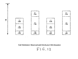
- FIG. 8 is a flow diagram of the call admission control process.
- FIG. 9 represents the four queues operating in an unbalanced call admission
- the following table shows how the states of the four phases change pursuant to the flow diagram of FIG. 8 as the calls (see FIG. 5C) are added: Call No. State of Phase 0 State of Phase 1 State of Phase 2 State of Phase 3 No call 16 16 16 16 1 14 14 14 14 2 10 14 10 14 3 3 14 10 14 4 3 7 10 14 5 0 7 7 14 6 0 4 7 11
- FIG. 11 shows a distribution of calls that increases the opportunities to concatenate calls.
- FIG. 12 shows a distribution of calls that tends to place calls from different cable modems in different queues to increase the opportunities to piggy back calls.
Landscapes
- Engineering & Computer Science (AREA)
- Signal Processing (AREA)
- Computer Networks & Wireless Communication (AREA)
- Multimedia (AREA)
- Computer Security & Cryptography (AREA)
- Business, Economics & Management (AREA)
- Databases & Information Systems (AREA)
- General Business, Economics & Management (AREA)
- General Engineering & Computer Science (AREA)
- Data Exchanges In Wide-Area Networks (AREA)
- Communication Control (AREA)
- Mobile Radio Communication Systems (AREA)
- Time-Division Multiplex Systems (AREA)
- Machine Translation (AREA)
- Devices For Executing Special Programs (AREA)
- Transmitters (AREA)
Abstract
Description
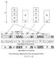
Total number of calls : N
Number of active calls : Na
Number of calls that go silent in this grant: n
In the example shown in the figure, N=Na=2.
NPB = (36- (21+11))/2 = 2 which is the correct number of piggybacks in this voice burst.
| Call No. | State of | State of | State of | State of |
| No | 16 | 16 | 16 | 16 |
| 1 | 14 | 14 | 14 | 14 |
| 2 | 10 | 14 | 10 | 14 |
| 3 | 3 | 14 | 10 | 14 |
| 4 | 3 | 7 | 10 | 14 |
| 5 | 0 | 7 | 7 | 14 |
| 6 | 0 | 4 | 7 | 11 |
| Call No. | State of | State of | State of | State of |
| No | 16 | 16 | 16 | 16 |
| 1 | 14 | 14 | 14 | 14 |
| 2 | 10 | 14 | 10 | 14 |
| 3 | 10 | 7 | 10 | 14 |
| 4 | 10 | 7 | 10 | 7 |
| 5 | 7 | 7 | 7 | 7 |
| 6 | 4 | 7 | 4 | 7 |
Claims (6)
- A method for timing the transmission of unsolicited grants (USGs) of bandwidth to transmit voice packets on a shared transmission medium characterized in that it comprises the steps of:initializing a control terminal to receive packets of voice calls having parameters including a bit rate, a packetization interval, and a call identification;creating a plurality of queues to define a corresponding plurality of phases at a sub-multiple of the packetization interval;admitting voice calls to the control terminal;distributing the voice calls among the queues in a predetermined order as the voice calls are admitted;removing the voice calls from the queues as the voice calls are terminated; andperiodically issuing at the phases defined by the queues USGs that include a call identification and a grant of bandwidth sufficient to transmit the packets.
- The method of claim 1, additionally comprising the step of deactivating a voice call in a queue when a silent period is detected in a queue so the size of the granted bandwidth excludes the deactivated voice call.
- The method of claim 2, additionally comprising the step of reactivating a voice call in a queue when a detected silent period ends.
- The method of claim 1, in which the bit rates and packetization intervals of all the voice calls are the same and all the admitted voice calls are distributed to each queue.
- The method of claim 1, in which the voice calls have different packetization intervals and the number of phases equals the least common multiple of the different packetization intervals divided by the the smallest packetization interval.
- The method of claim 1, in which the control terminal is a cable modem termination system (CMTS) and the shared transmission medium is a cable transmission system, the method additionally comprising the steps of receiving the USGs at cable modems connected to the cable transmission system and transmitting voice packets from the cable modems to the CMTS responsive to the received grants.
Applications Claiming Priority (11)
| Application Number | Priority Date | Filing Date | Title |
|---|---|---|---|
| US18247000P | 2000-02-15 | 2000-02-15 | |
| US182470P | 2000-02-15 | ||
| US24718800P | 2000-11-09 | 2000-11-09 | |
| US247188P | 2000-11-09 | ||
| US25441500P | 2000-12-08 | 2000-12-08 | |
| US254415P | 2000-12-08 | ||
| US26220101P | 2001-01-17 | 2001-01-17 | |
| US26220301P | 2001-01-17 | 2001-01-17 | |
| US262203P | 2001-01-17 | ||
| US262201P | 2001-01-17 | ||
| PCT/US2001/004904 WO2001061983A2 (en) | 2000-02-15 | 2001-02-15 | Voice architecture for transmission over a shared, contention based medium |
Publications (2)
| Publication Number | Publication Date |
|---|---|
| EP1256229A2 EP1256229A2 (en) | 2002-11-13 |
| EP1256229B1 true EP1256229B1 (en) | 2005-01-26 |
Family
ID=27539074
Family Applications (5)
| Application Number | Title | Priority Date | Filing Date |
|---|---|---|---|
| EP01910717A Expired - Lifetime EP1257514B1 (en) | 2000-02-15 | 2001-02-15 | System and method for combining data bandwidth requests by a data provider for transmission of data over an asynchronous communication medium |
| EP01910715A Expired - Lifetime EP1258101B1 (en) | 2000-02-15 | 2001-02-15 | Cable modem system and method for specialized data transfer |
| EP01918168A Expired - Lifetime EP1258102B1 (en) | 2000-02-15 | 2001-02-15 | Method for suppressing silence in voice traffic over an asynchronous communication medium |
| EP01910716A Expired - Lifetime EP1266526B1 (en) | 2000-02-15 | 2001-02-15 | Method for scheduling upstream communications |
| EP01920113A Expired - Lifetime EP1256229B1 (en) | 2000-02-15 | 2001-02-15 | Voice architecture for transmission over a shared, contention based medium |
Family Applications Before (4)
| Application Number | Title | Priority Date | Filing Date |
|---|---|---|---|
| EP01910717A Expired - Lifetime EP1257514B1 (en) | 2000-02-15 | 2001-02-15 | System and method for combining data bandwidth requests by a data provider for transmission of data over an asynchronous communication medium |
| EP01910715A Expired - Lifetime EP1258101B1 (en) | 2000-02-15 | 2001-02-15 | Cable modem system and method for specialized data transfer |
| EP01918168A Expired - Lifetime EP1258102B1 (en) | 2000-02-15 | 2001-02-15 | Method for suppressing silence in voice traffic over an asynchronous communication medium |
| EP01910716A Expired - Lifetime EP1266526B1 (en) | 2000-02-15 | 2001-02-15 | Method for scheduling upstream communications |
Country Status (6)
| Country | Link |
|---|---|
| US (1) | US7388884B2 (en) |
| EP (5) | EP1257514B1 (en) |
| AT (5) | ATE288168T1 (en) |
| AU (5) | AU2001238296A1 (en) |
| DE (3) | DE60137115D1 (en) |
| WO (5) | WO2001060767A2 (en) |
Families Citing this family (25)
| Publication number | Priority date | Publication date | Assignee | Title |
|---|---|---|---|---|
| US6804251B1 (en) * | 1998-11-12 | 2004-10-12 | Broadcom Corporation | System and method for multiplexing data from multiple sources |
| US6999414B2 (en) * | 1999-10-27 | 2006-02-14 | Broadcom Corporation | System and method for combining requests for data bandwidth by a data provider for transmission of data over an asynchronous communication medium |
| US7333495B2 (en) * | 1999-10-27 | 2008-02-19 | Broadcom Corporation | Method for scheduling upstream communications |
| US6993007B2 (en) * | 1999-10-27 | 2006-01-31 | Broadcom Corporation | System and method for suppressing silence in voice traffic over an asynchronous communication medium |
| US7769047B2 (en) * | 2001-02-15 | 2010-08-03 | Broadcom Corporation | Methods for specialized data transfer in a wireless communication system |
| US20020199200A1 (en) * | 2001-05-25 | 2002-12-26 | N2 Broadband, Inc. | System and method for scheduling the distribution of assets from multiple asset providers to multiple receivers |
| US7177324B1 (en) * | 2001-07-12 | 2007-02-13 | At&T Corp. | Network having bandwidth sharing |
| US8024766B2 (en) | 2001-08-01 | 2011-09-20 | Ericsson Television, Inc. | System and method for distributing network-based personal video |
| US20030041162A1 (en) * | 2001-08-27 | 2003-02-27 | Hochmuth Roland M. | System and method for communicating graphics images over a computer network |
| US7379472B2 (en) | 2001-09-27 | 2008-05-27 | Broadcom Corporation | Hardware filtering of unsolicited grant service extended headers |
| CN100380879C (en) * | 2002-02-06 | 2008-04-09 | 汤姆森许可公司 | Method and apparatus for concatenating and piggybacking data packets |
| US7319666B2 (en) * | 2002-02-06 | 2008-01-15 | Thomson Licensing | Method and apparatus for concatenating and piggybacking data packets |
| US7796583B1 (en) | 2002-07-17 | 2010-09-14 | Nortel Networks Limited | Packet handler for high-speed data networks |
| US7739359B1 (en) * | 2002-09-12 | 2010-06-15 | Cisco Technology, Inc. | Methods and apparatus for secure cable modem provisioning |
| US7568209B1 (en) | 2003-11-14 | 2009-07-28 | Tanderberg Television, Inc. | Method and system for the management of targeted material insertion using a campaign manager |
| EP1782560A4 (en) * | 2004-08-25 | 2011-05-11 | Thomson Licensing | Compression in cable data service |
| WO2007062108A2 (en) * | 2005-11-23 | 2007-05-31 | Pak Siripunkaw | Method of upgrading a platform in a subscriber gateway device |
| US8628522B2 (en) | 2007-05-21 | 2014-01-14 | Estech, Inc. (Endoscopic Technologies, Inc.) | Cardiac ablation systems and methods |
| US8108911B2 (en) | 2007-11-01 | 2012-01-31 | Comcast Cable Holdings, Llc | Method and system for directing user between captive and open domains |
| US20130236170A1 (en) * | 2010-11-24 | 2013-09-12 | Mitsubishi Electric Corporation | Communication apparatus |
| JP2011125039A (en) * | 2011-01-06 | 2011-06-23 | Thomson Licensing | Compression in cable data service |
| US9729431B1 (en) * | 2011-08-16 | 2017-08-08 | Marvell International Ltd. | Using standard fields to carry meta-information |
| US9788053B2 (en) * | 2015-09-09 | 2017-10-10 | Ericsson Ab | Fast channel change in a multicast adaptive bitrate (MABR) streaming network using HTTP download segment recovery in a dedicated bandwidth pipe |
| US9942290B2 (en) | 2015-09-09 | 2018-04-10 | Ericsson Ab | Fast channel change in a multicast adaptive bitrate (MABR) streaming network using HTTP download segment recovery in a shared progressive ABR download pipe |
| WO2018213647A1 (en) * | 2017-05-17 | 2018-11-22 | Cisco Technology, Inc. | Waterfall granting |
Family Cites Families (44)
| Publication number | Priority date | Publication date | Assignee | Title |
|---|---|---|---|---|
| US4534024A (en) | 1982-12-02 | 1985-08-06 | At&T Bell Laboratories | System and method for controlling a multiple access data communications system including both data packets and voice packets being communicated over a cable television system |
| US4712210A (en) | 1984-09-07 | 1987-12-08 | Lee Data Corporation | Signal conversion circuit for interconnecting coaxial cable and a twisted pair |
| US5341374A (en) | 1991-03-01 | 1994-08-23 | Trilan Systems Corporation | Communication network integrating voice data and video with distributed call processing |
| US5421030A (en) | 1991-09-17 | 1995-05-30 | Com21, Inc. | Communications system and method for bi-directional communications between an upstream control facility and downstream user terminals |
| US5425027A (en) | 1993-01-04 | 1995-06-13 | Com21, Inc. | Wide area fiber and TV cable fast packet cell network |
| US5539449A (en) | 1993-05-03 | 1996-07-23 | At&T Corp. | Integrated television services system |
| RO111887B1 (en) | 1993-05-28 | 1997-02-28 | Us West Technologies Inc | Method and network for the separation of telephonic services from special services |
| US5515379A (en) | 1993-10-18 | 1996-05-07 | Motorola, Inc. | Time slot allocation method |
| US5463624A (en) * | 1994-04-15 | 1995-10-31 | Dsc Communications Corporation | Bus arbitration method for telecommunications switching |
| US5570355A (en) | 1994-11-17 | 1996-10-29 | Lucent Technologies Inc. | Method and apparatus enabling synchronous transfer mode and packet mode access for multiple services on a broadband communication network |
| US5631908A (en) * | 1995-03-28 | 1997-05-20 | Digital Equipment Corporation | Method and apparatus for generating and implementing smooth schedules for forwarding data flows across cell-based switches |
| US5850400A (en) * | 1995-04-27 | 1998-12-15 | Next Level Communications | System, method, and apparatus for bidirectional transport of digital data between a digital network and a plurality of devices |
| US5742592A (en) | 1995-09-01 | 1998-04-21 | Motorola, Inc. | Method for communicating data in a wireless communication system |
| US5606561A (en) | 1995-07-28 | 1997-02-25 | Motorola, Inc. | Method, device/microprocessor, and computer software for providing packet fragmentation for fair, efficient downlink transmission with low packet delay |
| US5756280A (en) | 1995-10-03 | 1998-05-26 | International Business Machines Corporation | Multimedia distribution network including video switch |
| US5917822A (en) * | 1995-11-15 | 1999-06-29 | Xerox Corporation | Method for providing integrated packet services over a shared-media network |
| SE515901C2 (en) | 1995-12-28 | 2001-10-22 | Dynarc Ab | Resource management, plans and arrangements |
| US6055268A (en) | 1996-05-09 | 2000-04-25 | Texas Instruments Incorporated | Multimode digital modem |
| US6078564A (en) * | 1996-08-30 | 2000-06-20 | Lucent Technologies, Inc. | System for improving data throughput of a TCP/IP network connection with slow return channel |
| US5946323A (en) * | 1996-11-20 | 1999-08-31 | At&T Corp | Asynchronous transfer mode integrated access service |
| US5926478A (en) * | 1996-12-19 | 1999-07-20 | Ericsson, Inc. | Data transmission over a point-to-multipoint optical network |
| US6370571B1 (en) * | 1997-03-05 | 2002-04-09 | At Home Corporation | System and method for delivering high-performance online multimedia services |
| US5963557A (en) | 1997-04-11 | 1999-10-05 | Eng; John W. | High capacity reservation multiple access network with multiple shared unidirectional paths |
| US6249526B1 (en) | 1997-06-30 | 2001-06-19 | Intel Corporation | Versatile time division multiple access slot assignment unit |
| US6032197A (en) * | 1997-09-25 | 2000-02-29 | Microsoft Corporation | Data packet header compression for unidirectional transmission |
| WO1999018718A1 (en) * | 1997-10-02 | 1999-04-15 | Thomson Licensing S.A. | Multimedia decoder and bi-directional broadcast communication system |
| US6567416B1 (en) * | 1997-10-14 | 2003-05-20 | Lucent Technologies Inc. | Method for access control in a multiple access system for communications networks |
| US6137793A (en) * | 1997-12-05 | 2000-10-24 | Com21, Inc. | Reverse path multiplexer for use in high speed data transmissions |
| US6185224B1 (en) | 1998-01-12 | 2001-02-06 | Georgia Tech Research Corporation | System and method for communicating data in a cable network |
| US6233687B1 (en) * | 1998-01-21 | 2001-05-15 | Nortel Networks Limited | Method and apparatus for providing configuration information in a network |
| US6115394A (en) * | 1998-03-04 | 2000-09-05 | Ericsson Inc. | Methods, apparatus and computer program products for packet transport over wireless communication links |
| US6510162B1 (en) * | 1998-05-27 | 2003-01-21 | 3Com Corporation | System and method for managing channel usage in a data over cable system |
| US6272131B1 (en) | 1998-06-11 | 2001-08-07 | Synchrodyne Networks, Inc. | Integrated data packet network using a common time reference |
| US6230326B1 (en) * | 1998-07-30 | 2001-05-08 | Nortel Networks Limited | Method and apparatus for initialization of a cable modem |
| US6438123B1 (en) * | 1998-11-10 | 2002-08-20 | Cisco Technology, Inc. | Method and apparatus for supporting header suppression and multiple microflows in a network |
| US6804251B1 (en) | 1998-11-12 | 2004-10-12 | Broadcom Corporation | System and method for multiplexing data from multiple sources |
| US6618386B1 (en) * | 1999-03-04 | 2003-09-09 | Webtv Networks, Inc. | Hosting a cable modem in a computer using a virtual bridge |
| US6643780B1 (en) * | 1999-05-07 | 2003-11-04 | Ericsson Inc. | Modems that block data transfers during safe mode of operation and related methods |
| US6715075B1 (en) * | 1999-07-08 | 2004-03-30 | Intel Corporation | Providing a configuration file to a communication device |
| US6788707B1 (en) * | 1999-08-31 | 2004-09-07 | Broadcom Corporation | Method for the suppression and expansion of packet header information in cable modem and cable modem termination system devices |
| US7203164B2 (en) * | 1999-10-27 | 2007-04-10 | Broadcom Corporation | Voice architecture for transmission over a shared, contention based medium |
| US7164690B2 (en) * | 1999-12-23 | 2007-01-16 | Broadcom Corporation | Method for opening a proprietary MAC protocol in a non-DOCSIS modem compatibly with a DOCSIS modem |
| US6466986B1 (en) * | 1999-12-30 | 2002-10-15 | Nortel Networks Limited | Method and apparatus for providing dynamic host configuration protocol (DHCP) tagging |
| US7389527B2 (en) * | 2000-10-11 | 2008-06-17 | Broadcom Corporation | Cable modem system and method for supporting extended protocols |
-
2001
- 2001-02-15 WO PCT/US2001/004820 patent/WO2001060767A2/en active Application Filing
- 2001-02-15 AU AU2001238296A patent/AU2001238296A1/en not_active Abandoned
- 2001-02-15 AT AT01920113T patent/ATE288168T1/en not_active IP Right Cessation
- 2001-02-15 EP EP01910717A patent/EP1257514B1/en not_active Expired - Lifetime
- 2001-02-15 AU AU2001238297A patent/AU2001238297A1/en not_active Abandoned
- 2001-02-15 AU AU2001245274A patent/AU2001245274A1/en not_active Abandoned
- 2001-02-15 WO PCT/US2001/004904 patent/WO2001061983A2/en active IP Right Grant
- 2001-02-15 EP EP01910715A patent/EP1258101B1/en not_active Expired - Lifetime
- 2001-02-15 WO PCT/US2001/004818 patent/WO2001061924A2/en active IP Right Grant
- 2001-02-15 DE DE60137115T patent/DE60137115D1/en not_active Expired - Lifetime
- 2001-02-15 DE DE60108612T patent/DE60108612T2/en not_active Expired - Lifetime
- 2001-02-15 AU AU2001238298A patent/AU2001238298A1/en not_active Abandoned
- 2001-02-15 WO PCT/US2001/004819 patent/WO2001062008A2/en active Application Filing
- 2001-02-15 EP EP01918168A patent/EP1258102B1/en not_active Expired - Lifetime
- 2001-02-15 AT AT01910717T patent/ATE418528T1/en not_active IP Right Cessation
- 2001-02-15 EP EP01910716A patent/EP1266526B1/en not_active Expired - Lifetime
- 2001-02-15 WO PCT/US2001/004841 patent/WO2001061925A2/en active Application Filing
- 2001-02-15 AT AT01910716T patent/ATE555604T1/en active
- 2001-02-15 AU AU2001247200A patent/AU2001247200A1/en not_active Abandoned
- 2001-02-15 AT AT01918168T patent/ATE529969T1/en not_active IP Right Cessation
- 2001-02-15 US US09/783,403 patent/US7388884B2/en not_active Expired - Fee Related
- 2001-02-15 DE DE60132071T patent/DE60132071T2/en not_active Expired - Lifetime
- 2001-02-15 AT AT01910715T patent/ATE382240T1/en not_active IP Right Cessation
- 2001-02-15 EP EP01920113A patent/EP1256229B1/en not_active Expired - Lifetime
Also Published As
Similar Documents
| Publication | Publication Date | Title |
|---|---|---|
| US7203164B2 (en) | Voice architecture for transmission over a shared, contention based medium | |
| EP1256229B1 (en) | Voice architecture for transmission over a shared, contention based medium | |
| US5570355A (en) | Method and apparatus enabling synchronous transfer mode and packet mode access for multiple services on a broadband communication network | |
| EP1326389B1 (en) | Method, system, and computer program product for synchronizing voice traffic with minimum latency | |
| US6684273B2 (en) | Auto-adaptive jitter buffer method for data stream involves comparing delay of packet with predefined value and using comparison result to set buffer size | |
| US7103063B2 (en) | Apparatus and method for facilitating data packet transportation | |
| JP3061825B2 (en) | Communications system | |
| US6014545A (en) | Growable architecture for high-speed two-way data services over CATV networks | |
| EP0745295B1 (en) | Multimedia multiplexing device and method using dynamic packet segmentation | |
| US6185635B1 (en) | Method and circuit for transporting data based on the content of ingress data words and egress data words | |
| JP3417512B2 (en) | Delay minimization system with guaranteed bandwidth delivery for real-time traffic | |
| US6847635B1 (en) | Method to transmit silence compressed voice over IP efficiently in DOCSIS cable networks | |
| US7269159B1 (en) | Upstream bandwidth allocation for packet telephony in a shared-media packet-switched access network | |
| EP1298860B1 (en) | Method and system for flexible channel association | |
| US20070076766A1 (en) | System And Method For A Guaranteed Delay Jitter Bound When Scheduling Bandwidth Grants For Voice Calls Via A Cable Network | |
| US20090268751A1 (en) | Supporting Multiple Logical Channels In A Physical Interface | |
| US9055483B2 (en) | Scheduling in a two-tier network | |
| JP2002515198A (en) | Transmission mechanism of constant bit rate in contention-based medium access control | |
| US10841674B2 (en) | Timeslot management method, a related network terminator, a related line terminator and an upstream signal frame structure for a time division multiple access system | |
| CN1484933A (en) | Point-to-multipoint passive optical network that utilizes variable-length packets and variable-length upsteam tine slots | |
| US20040062260A1 (en) | Multi-level jitter control | |
| US6275505B1 (en) | Method and apparatus for packetizing data into a data stream | |
| US6330251B1 (en) | Method and apparatus for data extraction from a bit stream | |
| US6771655B1 (en) | Method and apparatus for managing data transportation | |
| US8254394B1 (en) | Technique for providing constant bit rate (CBR) service over a time-slotted access channel |
Legal Events
| Date | Code | Title | Description |
|---|---|---|---|
| PUAI | Public reference made under article 153(3) epc to a published international application that has entered the european phase |
Free format text: ORIGINAL CODE: 0009012 |
|
| 17P | Request for examination filed |
Effective date: 20020905 |
|
| AK | Designated contracting states |
Kind code of ref document: A2 Designated state(s): AT BE CH CY DE DK ES FI FR GB GR IE IT LI LU MC NL PT SE TR |
|
| AX | Request for extension of the european patent |
Free format text: AL;LT;LV;MK;RO;SI |
|
| GRAP | Despatch of communication of intention to grant a patent |
Free format text: ORIGINAL CODE: EPIDOSNIGR1 |
|
| GRAS | Grant fee paid |
Free format text: ORIGINAL CODE: EPIDOSNIGR3 |
|
| GRAA | (expected) grant |
Free format text: ORIGINAL CODE: 0009210 |
|
| AK | Designated contracting states |
Kind code of ref document: B1 Designated state(s): AT BE CH CY DE DK ES FI FR GB GR IE IT LI LU MC NL PT SE TR |
|
| PG25 | Lapsed in a contracting state [announced via postgrant information from national office to epo] |
Ref country code: IT Free format text: LAPSE BECAUSE OF FAILURE TO SUBMIT A TRANSLATION OF THE DESCRIPTION OR TO PAY THE FEE WITHIN THE PRESCRIBED TIME-LIMIT;WARNING: LAPSES OF ITALIAN PATENTS WITH EFFECTIVE DATE BEFORE 2007 MAY HAVE OCCURRED AT ANY TIME BEFORE 2007. THE CORRECT EFFECTIVE DATE MAY BE DIFFERENT FROM THE ONE RECORDED. Effective date: 20050126 Ref country code: NL Free format text: LAPSE BECAUSE OF FAILURE TO SUBMIT A TRANSLATION OF THE DESCRIPTION OR TO PAY THE FEE WITHIN THE PRESCRIBED TIME-LIMIT Effective date: 20050126 Ref country code: FI Free format text: LAPSE BECAUSE OF FAILURE TO SUBMIT A TRANSLATION OF THE DESCRIPTION OR TO PAY THE FEE WITHIN THE PRESCRIBED TIME-LIMIT Effective date: 20050126 Ref country code: CH Free format text: LAPSE BECAUSE OF FAILURE TO SUBMIT A TRANSLATION OF THE DESCRIPTION OR TO PAY THE FEE WITHIN THE PRESCRIBED TIME-LIMIT Effective date: 20050126 Ref country code: LI Free format text: LAPSE BECAUSE OF FAILURE TO SUBMIT A TRANSLATION OF THE DESCRIPTION OR TO PAY THE FEE WITHIN THE PRESCRIBED TIME-LIMIT Effective date: 20050126 Ref country code: TR Free format text: LAPSE BECAUSE OF FAILURE TO SUBMIT A TRANSLATION OF THE DESCRIPTION OR TO PAY THE FEE WITHIN THE PRESCRIBED TIME-LIMIT Effective date: 20050126 Ref country code: AT Free format text: LAPSE BECAUSE OF FAILURE TO SUBMIT A TRANSLATION OF THE DESCRIPTION OR TO PAY THE FEE WITHIN THE PRESCRIBED TIME-LIMIT Effective date: 20050126 Ref country code: BE Free format text: LAPSE BECAUSE OF FAILURE TO SUBMIT A TRANSLATION OF THE DESCRIPTION OR TO PAY THE FEE WITHIN THE PRESCRIBED TIME-LIMIT Effective date: 20050126 |
|
| REG | Reference to a national code |
Ref country code: GB Ref legal event code: FG4D |
|
| REG | Reference to a national code |
Ref country code: CH Ref legal event code: EP |
|
| PG25 | Lapsed in a contracting state [announced via postgrant information from national office to epo] |
Ref country code: IE Free format text: LAPSE BECAUSE OF NON-PAYMENT OF DUE FEES Effective date: 20050215 Ref country code: CY Free format text: LAPSE BECAUSE OF FAILURE TO SUBMIT A TRANSLATION OF THE DESCRIPTION OR TO PAY THE FEE WITHIN THE PRESCRIBED TIME-LIMIT Effective date: 20050215 Ref country code: LU Free format text: LAPSE BECAUSE OF NON-PAYMENT OF DUE FEES Effective date: 20050215 |
|
| REG | Reference to a national code |
Ref country code: IE Ref legal event code: FG4D |
|
| PG25 | Lapsed in a contracting state [announced via postgrant information from national office to epo] |
Ref country code: MC Free format text: LAPSE BECAUSE OF NON-PAYMENT OF DUE FEES Effective date: 20050228 |
|
| REF | Corresponds to: |
Ref document number: 60108612 Country of ref document: DE Date of ref document: 20050303 Kind code of ref document: P |
|
| PG25 | Lapsed in a contracting state [announced via postgrant information from national office to epo] |
Ref country code: SE Free format text: LAPSE BECAUSE OF FAILURE TO SUBMIT A TRANSLATION OF THE DESCRIPTION OR TO PAY THE FEE WITHIN THE PRESCRIBED TIME-LIMIT Effective date: 20050426 Ref country code: GR Free format text: LAPSE BECAUSE OF FAILURE TO SUBMIT A TRANSLATION OF THE DESCRIPTION OR TO PAY THE FEE WITHIN THE PRESCRIBED TIME-LIMIT Effective date: 20050426 Ref country code: DK Free format text: LAPSE BECAUSE OF FAILURE TO SUBMIT A TRANSLATION OF THE DESCRIPTION OR TO PAY THE FEE WITHIN THE PRESCRIBED TIME-LIMIT Effective date: 20050426 |
|
| PG25 | Lapsed in a contracting state [announced via postgrant information from national office to epo] |
Ref country code: ES Free format text: LAPSE BECAUSE OF FAILURE TO SUBMIT A TRANSLATION OF THE DESCRIPTION OR TO PAY THE FEE WITHIN THE PRESCRIBED TIME-LIMIT Effective date: 20050507 |
|
| NLV1 | Nl: lapsed or annulled due to failure to fulfill the requirements of art. 29p and 29m of the patents act | ||
| REG | Reference to a national code |
Ref country code: CH Ref legal event code: PL |
|
| REG | Reference to a national code |
Ref country code: IE Ref legal event code: MM4A |
|
| PLBE | No opposition filed within time limit |
Free format text: ORIGINAL CODE: 0009261 |
|
| STAA | Information on the status of an ep patent application or granted ep patent |
Free format text: STATUS: NO OPPOSITION FILED WITHIN TIME LIMIT |
|
| ET | Fr: translation filed | ||
| 26N | No opposition filed |
Effective date: 20051027 |
|
| PG25 | Lapsed in a contracting state [announced via postgrant information from national office to epo] |
Ref country code: PT Free format text: LAPSE BECAUSE OF NON-PAYMENT OF DUE FEES Effective date: 20050626 |
|
| PGFP | Annual fee paid to national office [announced via postgrant information from national office to epo] |
Ref country code: FR Payment date: 20130315 Year of fee payment: 13 |
|
| PGFP | Annual fee paid to national office [announced via postgrant information from national office to epo] |
Ref country code: GB Payment date: 20140220 Year of fee payment: 14 |
|
| REG | Reference to a national code |
Ref country code: FR Ref legal event code: ST Effective date: 20141031 |
|
| PG25 | Lapsed in a contracting state [announced via postgrant information from national office to epo] |
Ref country code: FR Free format text: LAPSE BECAUSE OF NON-PAYMENT OF DUE FEES Effective date: 20140228 |
|
| GBPC | Gb: european patent ceased through non-payment of renewal fee |
Effective date: 20150215 |
|
| PG25 | Lapsed in a contracting state [announced via postgrant information from national office to epo] |
Ref country code: GB Free format text: LAPSE BECAUSE OF NON-PAYMENT OF DUE FEES Effective date: 20150215 |
|
| PGFP | Annual fee paid to national office [announced via postgrant information from national office to epo] |
Ref country code: DE Payment date: 20160229 Year of fee payment: 16 |
|
| REG | Reference to a national code |
Ref country code: DE Ref legal event code: R082 Ref document number: 60108612 Country of ref document: DE Representative=s name: BOSCH JEHLE PATENTANWALTSGESELLSCHAFT MBH, DE Ref country code: DE Ref legal event code: R081 Ref document number: 60108612 Country of ref document: DE Owner name: AVAGO TECHNOLOGIES GENERAL IP (SINGAPORE) PTE., SG Free format text: FORMER OWNER: BROADCOM CORP., IRVINE, CALIF., US |
|
| REG | Reference to a national code |
Ref country code: DE Ref legal event code: R119 Ref document number: 60108612 Country of ref document: DE |
|
| PG25 | Lapsed in a contracting state [announced via postgrant information from national office to epo] |
Ref country code: DE Free format text: LAPSE BECAUSE OF NON-PAYMENT OF DUE FEES Effective date: 20170901 |