EP1251710A1 - Method and apparatus for migrating subscribers between networks - Google Patents
Method and apparatus for migrating subscribers between networks Download PDFInfo
- Publication number
- EP1251710A1 EP1251710A1 EP02252084A EP02252084A EP1251710A1 EP 1251710 A1 EP1251710 A1 EP 1251710A1 EP 02252084 A EP02252084 A EP 02252084A EP 02252084 A EP02252084 A EP 02252084A EP 1251710 A1 EP1251710 A1 EP 1251710A1
- Authority
- EP
- European Patent Office
- Prior art keywords
- network
- call
- subscribers
- gmsc
- hlr
- Prior art date
- Legal status (The legal status is an assumption and is not a legal conclusion. Google has not performed a legal analysis and makes no representation as to the accuracy of the status listed.)
- Withdrawn
Links
Images


Classifications
-
- H—ELECTRICITY
- H04—ELECTRIC COMMUNICATION TECHNIQUE
- H04W—WIRELESS COMMUNICATION NETWORKS
- H04W8/00—Network data management
- H04W8/26—Network addressing or numbering for mobility support
- H04W8/28—Number portability ; Network address portability
Definitions
- This invention relates to communication systems, including but not limited to migration of subscribers between wireless communication systems.
- Various types of cellular communication systems are known to provide radio telephone service to a large number of mobile subscribers using a relatively small number of frequencies. Such service is provided by dividing a service area into a number of cells and reusing the frequencies in non-adjacent cells. This cellular principle has permitted a large growth in the amount of wireless telecommunications that may be carried over the allocated radio spectrum, thus providing significant expansion in the number of wireless communication subscribers.
- Different cellular technologies or protocols include analog, time division multiple access (TDMA), code division multiple access (CDMA), Global System for Mobile Communications (GSM), and Universal Mobile Telecommunications System (UMTS).
- mobile network providers also known as service providers or network operators
- service providers or network operators desire to change technologies, for example, to abandon less efficient technologies or to obtain more services, resources, efficiency, and/or voice quality provided by more advanced technologies.
- Issues regarding the migration of subscribers from a network based on one technology to a network based on another technology need to be resolved.
- the network provider may prefer to maintain the same phone numbers for its subscribers and to have the migration appear seamless to its subscribers.
- a method of migrating subscribers from a first network to a second network comprises the steps of transferring at least one connection from at least one other network to a gateway mobile switching center of the second network and directing a call from the at least one other network to a subscriber at the first network to the gateway mobile switching center of the second network.
- the following describes an apparatus for and method of migrating subscribers from a first network to a second network without requiring the subscribers to obtain new phone numbers.
- GMSC gateway mobile switching center
- All calls for the first network and the second network are directed to the GMSC of the second network, which queries the home location register (HLR) of the second network for terminating subscriber routing information.
- HLR home location register
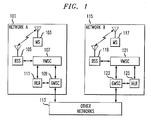
- FIG. 1 A block diagram of a first network and a second network is shown in FIG. 1.
- a network provider operates Network A ("first network") 101 and has a plurality of mobile stations or mobile subscribers 103 (only one is shown for the sake of simplicity).
- the MS 103 communicates via wireless communication resources to one or more base station systems 105 (only one is shown for the sake of simplicity).
- Inbound and outbound communications from/to the subscribers 103 are controlled via the network's 101 infrastructure, including devices such as a visited mobile switching center 107, an HLR 111, and a GMSC 109, as known in the art.
- the GMSC 109 receives calls from other networks 113, including wireline networks, such as the Public Switched Telephone Network (PSTN), and wireless networks, such as a Public Land Mobile Network (PLMN), analog, time division multiple access (TDMA), code division multiple access (CDMA), Global System for Mobile Communications (GSM), and Universal Mobile Telecommunications System (UMTS), among others.
- PSTN Public Switched Telephone Network
- PLMN Public Land Mobile Network
- TDMA time division multiple access
- CDMA code division multiple access
- GSM Global System for Mobile Communications
- UMTS Universal Mobile Telecommunications System
- Network B 115 is built according to the network provider's specifications, including appropriate infrastructure devices, e.g., one or more BSSs 119, one or more VMSCs 121, a GMSC 123, and an HLR 125, prior to registration or transfer of any of the service provider's subscribers 103 to Network B 115.
- Network B 115 is also connected to any other networks 113, such as those described above, with which communication is desired. All subscriber data from Network A 101 may be pre-populated in the HLR 125 of Network B 115, although the subscribers may not yet be activated.
- Network B 115 As the network provider is ready to migrate a subscriber from Network A 101 to Network B 115, the network provider activates the HLR for that subscriber in Network B 115. Subscribers may be activated one or more at a time. Network B 115 may be tested using one or more mobile subscribers 117 prior to bringing the new network 115 on line for present subscribers 103. Prior to bringing Network B fully on-line, trunks from Network A 101 to the other networks 113 must be moved to the GMSC 123 of Network B 115.
- Network A 101 and Network B 115 may be any wireless networks, such as analog, TDMA, CDMA, CDMA 2000, UMTS, and GSM.
- the network provider may desire to migrate its subscribers from a TDMA system to a GSM system.
- FIG. 2 A block diagram showing the first network interconnected with the second network is shown in FIG. 2.
- Network A 101 is disconnected from the other networks 113, and all calls directed to Network A 101 by routing them to the GMCS 123 based on the called or dialed number. Connections between Network A 101 and Network B are established to enable calls to be forwarded between the networks, and particularly for incoming calls for Network A 101 to be forwarded from the GMSC 123 to Network A 101. All calls directed to Network B 115 are also directed to the GMSC 123 of Network B 115.
- the GMSC 123 is an interface point to the other networks 113 and typically queries the HLR 125 and routes calls to an appropriate (V)MSC or GMSC.
- Interconnections between Network A 101 and Network B 115 are also established to enable calls to be sent on from the GMSC 123 to Network A 101.
- trunks are established from the other networks 113 to the GMSC 123 of Network B 115.
- the routing tables in the other networks 113 are updated to route calls directed to Network A 101 and calls directed to Network B 115 to use the trunks to the GMSC 123 of Network B 115.
- the trunks from the other networks 113 to the GMSC 109 are then removed.
- Each subscriber's directory number(s), features, and services are provisioned in the HLR 125 of Network B 115, thereby providing the capability for the subscriber's current (Network A 101) directory number to continue to be used by the subscriber when the subscriber migrates to Network B 115.
- Each subscriber's number(s) as well as dialing plan or service features are activated by the service provider at the HLR 125 of Network B 115, typically as the network provider is ready to provide service to those subscribers.
- the GMSC 123 of Network B needs to route calls for subscribers 103 in Network A 101 and subscribers 117 in Network B 115 to the appropriate network. To accomplish this task, the GMSC 123 queries the HLR 125 of Network B 115 for routing information for all calls, whether they are for Network A 101 or Network B 115. When the subscriber is provisioned and activated at the HLR 125, the call is routed to Network B 115. When the subscriber is not provisioned or not active at the HLR 125, the call is routed to Network A 101.
- FIG. 2 Examples of call flows for both networks are shown in FIG. 2.
- a call flow for a call directed to a subscriber 117 that is registered at Network B's HLR 125 is indicated by the numbers 1 through 6 in circles.
- Calls for subscribers activated at Network B 115 take place as they would normally take place in a system of the technology of Network B 115.
- the call comes in (1) to the GMSC 123 from one of the other networks 113.
- the GMSC 123 queries (2) the HLR 125 of Network B 115, which returns (3) routing information for the subscriber 117 to the GMSC 123.
- the GMSC 123 routes (4) the call to the appropriate VMSC 121, which routes (5) the call to the appropriate base station 119, which directs (6) the call in a wireless fashion to the MS 117.
- the HLR 125 may send a message directed to Network A's HLR 111 that indicates that the subscriber is registered and active on Network B 115. In response to this message, Network A's HLR 111 may delete or deregister the HLR's record for the subscriber.
- a call flow for a call directed to a subscriber 103 that is registered at Network A's HLR 111, but not Network B's HLR 125, is indicated by the numbers 1 through 9 in squares.
- the call comes in [1] to the GMSC 123 from one of the other networks 113.
- the GMSC 123 queries [2] the HLR 125 of Network B 115, which returns [3], to the GMSC 123, a message indicating that the subscriber 103 is not active or provisioned in the HLR 125.
- the GMSC 123 then routes [4] the call to Network A 101.
- the call may, for example, be routed to the GMSC 109 of Network A. At this point, the call proceeds as a call normally proceeds in Network A.
- the GMSC 109 queries [5] the HLR 111 of Network A 101, which returns [6] routing information for the subscriber 103 to the GMSC 109.
- the GMSC 109 routes [7] the call to the appropriate VMSC 107, which routes [8] the call to the appropriate base station 105, which directs [9] the call in a wireless fashion to the MS 103.
- FIG. 3 A flowchart illustrating a method of migrating subscribers from a first network to a second network is shown in FIG. 3.
- Network B 115 is installed and made operational, e.g., the GMSC 123 and the HLR 125 of Network B 115.
- connections, such as trunks, between Network A 101 (the first network) and the other networks 113 are transferred from Network A 101 to the GMSC 123 of Network B 115 (the second network).
- calls from the other networks 113 for Network A and Network B are directed to the GMSC 123 of Network B 115.
- the GMSC 123 queries the HLR 125 for routing information to the call.
- step 311 When routing information for the call is not available at step 309, the process continues with step 311, where the call is routed to Network A 101.
- the HLR 111 of Network A 101 is queried for routing information for the call.
- the call is then routed according to the routing information. In the event that routing information is not available for the call at Network A 101, the call is rejected.
- step 313 When routing information for the call is available at step 309, the process continues with step 313, where the call is routed to Network B 115.
- Outbound calls (calls from a Network B subscriber 117 to one of the other networks 113) for Network B subscribers 117 are handled normally for subscribers activated at Network B 115.
- Outbound calls for Network A subscribers 103 are forwarded to Network B, where they are routed to other networks 113 by tandem switching.
- FIG. 4 A timing diagram illustrating the migration of subscribers from a first network to a second network is shown in FIG. 4.
- the timing diagram shows the total combined network capacity for both networks as time passes.
- a linear decrease/increase in capacity is shown for network A/B for the sake of simplicity, although a continual, but not linear, decrease/increase is likely to occur.
- Prior to Network B being placed on-line all subscribers 103 for the network provider are registered at Network A 101 and all traffic is at Network A. As subscribers 103 migrate to Network B, which process is controlled by the network provider, less Network A 101 traffic exists and more subscribers 117 are registered/located at Network B 115 and traffic at Network B increases.
- Network A may be decommissioned and taken off line.
- Network A may be utilized to service subscribers that have dual-mode subscriber devices, i.e., subscribers that operate on both Network A 101 and Network B 115.
- the network provider may opt to leave Network A 101 active, at least for a time, for example, because subscribers wish to utilize Network A 101 for various reasons or because the network provider intends to sell the system.
- the GMSC 123 of Network B needs to have the capacity to handle calls for both Network A and Network B, plus any new subscribers that may subscribe to the network during the migration period.
- a separate HLR is shown for the two networks, a single dual-mode HLR (one that handles the technologies for both Network A and Network B) may be utilized.
- the GMSC 123 query of a dual-mode HLR 125 may yield routing for a call to a particular network, i.e., Network A 101 or Network B, rather than provision and activation information for the called party at Network B 115.
- each GMSC 109 or 123 may be co-located with a VMSC 107 or 121 in the GMSC's associated network.
- the present invention gives a network provider the ability to migrate from one network to another network, regardless of the technology of either network, without requiring its subscribers to change phone numbers. Subscribers are also able to continue utilizing ancillary items associated with the phone number, such as business cards, stationary, and advertising media. Unless the subscriber needs to change phones to accommodate the second network's technology, e.g., when the subscriber does not have a dual-mode phone, the user will not experience a noticeable loss in service, provided the service provide registers the subscriber at the second network.
Abstract
Subscribers (103) are migrated from a first network (101) to a second
network (115). Once the second network (115) is ready for traffic, connections
from other networks (113) to the first network (101) are effectively transferred to
the gateway mobile switching center (GMSC) (123) of the second network (115).
All calls for the first network (101) and the second network (115) are directed to
the GMSC (123) of the second network, which queries the home location register
(HLR) (125) of the second network (115) for routing information. When a
subscriber (117) is provisioned and activated at this HLR (125), the call is routed
within the second network (115). When a subscriber (103) is not provisioned or
activated at this HLR (125), the call is routed to the first network (101).
Description
- This invention relates to communication systems, including but not limited to migration of subscribers between wireless communication systems.
- Various types of cellular communication systems are known to provide radio telephone service to a large number of mobile subscribers using a relatively small number of frequencies. Such service is provided by dividing a service area into a number of cells and reusing the frequencies in non-adjacent cells. This cellular principle has permitted a large growth in the amount of wireless telecommunications that may be carried over the allocated radio spectrum, thus providing significant expansion in the number of wireless communication subscribers. Different cellular technologies or protocols include analog, time division multiple access (TDMA), code division multiple access (CDMA), Global System for Mobile Communications (GSM), and Universal Mobile Telecommunications System (UMTS).
- As communication systems evolve and provide different services, mobile network providers, also known as service providers or network operators, desire to change technologies, for example, to abandon less efficient technologies or to obtain more services, resources, efficiency, and/or voice quality provided by more advanced technologies. Issues regarding the migration of subscribers from a network based on one technology to a network based on another technology need to be resolved. For example, the network provider may prefer to maintain the same phone numbers for its subscribers and to have the migration appear seamless to its subscribers.
- Accordingly, there is a need for a method and apparatus to migrate subscribers between networks based on different technologies.
- A method of migrating subscribers from a first network to a second network comprises the steps of transferring at least one connection from at least one other network to a gateway mobile switching center of the second network and directing a call from the at least one other network to a subscriber at the first network to the gateway mobile switching center of the second network.
-
- FIG. 1 is a block diagram of a first network and a second network in accordance with the invention.
- FIG. 2 is a block diagram showing the first network interconnected with the second network in accordance with the invention.
- FIG. 3 is a flowchart showing a method of migrating subscribers from a first network to a second network in accordance with the invention.
- FIG. 4 is a timing diagram showing the migration of subscribers from a first network to a second network in accordance with the invention.
-
- The following describes an apparatus for and method of migrating subscribers from a first network to a second network without requiring the subscribers to obtain new phone numbers. Once the second network is ready for traffic, connections from other networks to the first network are effectively transferred to the gateway mobile switching center (GMSC) of the second network. All calls for the first network and the second network are directed to the GMSC of the second network, which queries the home location register (HLR) of the second network for terminating subscriber routing information. When a subscriber is provisioned and activated at this HLR, the call is routed within the second network. When a subscriber is not provisioned or activated at this HLR, the call is routed to the first network.
- A block diagram of a first network and a second network is shown in FIG. 1. A network provider operates Network A ("first network") 101 and has a plurality of mobile stations or mobile subscribers 103 (only one is shown for the sake of simplicity). The MS 103 communicates via wireless communication resources to one or more base station systems 105 (only one is shown for the sake of simplicity). Inbound and outbound communications from/to the
subscribers 103 are controlled via the network's 101 infrastructure, including devices such as a visitedmobile switching center 107, anHLR 111, and a GMSC 109, as known in the art. The GMSC 109 receives calls fromother networks 113, including wireline networks, such as the Public Switched Telephone Network (PSTN), and wireless networks, such as a Public Land Mobile Network (PLMN), analog, time division multiple access (TDMA), code division multiple access (CDMA), Global System for Mobile Communications (GSM), and Universal Mobile Telecommunications System (UMTS), among others. The GMSC 109 routes calls from the other networks and from within thenetwork 101 to thesubscribers 103 in thenetwork 101. Other infrastructure devices may also be present, but are not shown for the sake of simplicity of the drawing. - In order to facilitate subscriber migration from Network A 101 to Network B ("second network") 115 for the network provider's
subscribers 103,Network B 115 is built according to the network provider's specifications, including appropriate infrastructure devices, e.g., one ormore BSSs 119, one or more VMSCs 121, a GMSC 123, and anHLR 125, prior to registration or transfer of any of the service provider'ssubscribers 103 toNetwork B 115.Network B 115 is also connected to anyother networks 113, such as those described above, with which communication is desired. All subscriber data from Network A 101 may be pre-populated in theHLR 125 of Network B 115, although the subscribers may not yet be activated. As the network provider is ready to migrate a subscriber from Network A 101 toNetwork B 115, the network provider activates the HLR for that subscriber inNetwork B 115. Subscribers may be activated one or more at a time. Network B 115 may be tested using one or moremobile subscribers 117 prior to bringing thenew network 115 on line forpresent subscribers 103. Prior to bringing Network B fully on-line, trunks from Network A 101 to theother networks 113 must be moved to the GMSC 123 of Network B 115. - Network A 101 and Network B 115 may be any wireless networks, such as analog, TDMA, CDMA, CDMA 2000, UMTS, and GSM. For example, the network provider may desire to migrate its subscribers from a TDMA system to a GSM system.
- A block diagram showing the first network interconnected with the second network is shown in FIG. 2. Network A 101 is disconnected from the
other networks 113, and all calls directed to Network A 101 by routing them to the GMCS 123 based on the called or dialed number. Connections between Network A 101 and Network B are established to enable calls to be forwarded between the networks, and particularly for incoming calls for Network A 101 to be forwarded from the GMSC 123 to Network A 101. All calls directed to Network B 115 are also directed to the GMSC 123 of Network B 115. The GMSC 123 is an interface point to theother networks 113 and typically queries theHLR 125 and routes calls to an appropriate (V)MSC or GMSC. Interconnections between Network A 101 and Network B 115 are also established to enable calls to be sent on from the GMSC 123 to Network A 101. For example, trunks are established from theother networks 113 to the GMSC 123 of Network B 115. The routing tables in theother networks 113 are updated to route calls directed to Network A 101 and calls directed to Network B 115 to use the trunks to the GMSC 123 of Network B 115. The trunks from theother networks 113 to the GMSC 109 are then removed. Each subscriber's directory number(s), features, and services are provisioned in theHLR 125 ofNetwork B 115, thereby providing the capability for the subscriber's current (Network A 101) directory number to continue to be used by the subscriber when the subscriber migrates toNetwork B 115. Each subscriber's number(s) as well as dialing plan or service features are activated by the service provider at the HLR 125 of Network B 115, typically as the network provider is ready to provide service to those subscribers. - The GMSC 123 of Network B needs to route calls for
subscribers 103 in Network A 101 andsubscribers 117 in Network B 115 to the appropriate network. To accomplish this task, the GMSC 123 queries theHLR 125 of Network B 115 for routing information for all calls, whether they are for Network A 101 orNetwork B 115. When the subscriber is provisioned and activated at theHLR 125, the call is routed toNetwork B 115. When the subscriber is not provisioned or not active at theHLR 125, the call is routed toNetwork A 101. - Examples of call flows for both networks are shown in FIG. 2. A call flow for a call directed to a
subscriber 117 that is registered at Network B's HLR 125 is indicated by the numbers 1 through 6 in circles. Calls for subscribers activated at Network B 115 take place as they would normally take place in a system of the technology of Network B 115. The call comes in (1) to the GMSC 123 from one of theother networks 113. The GMSC 123 queries (2) theHLR 125 ofNetwork B 115, which returns (3) routing information for thesubscriber 117 to the GMSC 123. The GMSC 123 routes (4) the call to the appropriate VMSC 121, which routes (5) the call to theappropriate base station 119, which directs (6) the call in a wireless fashion to the MS 117. Optionally, the HLR 125 may send a message directed to Network A's HLR 111 that indicates that the subscriber is registered and active onNetwork B 115. In response to this message, Network A'sHLR 111 may delete or deregister the HLR's record for the subscriber. - A call flow for a call directed to a
subscriber 103 that is registered at Network A'sHLR 111, but not Network B'sHLR 125, is indicated by the numbers 1 through 9 in squares. The call comes in [1] to the GMSC 123 from one of theother networks 113. TheGMSC 123 queries [2] theHLR 125 ofNetwork B 115, which returns [3], to theGMSC 123, a message indicating that thesubscriber 103 is not active or provisioned in theHLR 125. TheGMSC 123 then routes [4] the call toNetwork A 101. The call may, for example, be routed to theGMSC 109 of Network A. At this point, the call proceeds as a call normally proceeds in Network A. TheGMSC 109 queries [5] theHLR 111 ofNetwork A 101, which returns [6] routing information for thesubscriber 103 to theGMSC 109. TheGMSC 109 routes [7] the call to theappropriate VMSC 107, which routes [8] the call to theappropriate base station 105, which directs [9] the call in a wireless fashion to theMS 103. - A flowchart illustrating a method of migrating subscribers from a first network to a second network is shown in FIG. 3. At
step 301,Network B 115 is installed and made operational, e.g., theGMSC 123 and theHLR 125 ofNetwork B 115. Atstep 303, connections, such as trunks, between Network A 101 (the first network) and theother networks 113 are transferred fromNetwork A 101 to theGMSC 123 of Network B 115 (the second network). Atstep 305, calls from theother networks 113 for Network A and Network B are directed to theGMSC 123 ofNetwork B 115. Atstep 307, upon receipt of a call, theGMSC 123 queries theHLR 125 for routing information to the call. When routing information for the call is not available atstep 309, the process continues withstep 311, where the call is routed toNetwork A 101. TheHLR 111 ofNetwork A 101 is queried for routing information for the call. The call is then routed according to the routing information. In the event that routing information is not available for the call atNetwork A 101, the call is rejected. When routing information for the call is available atstep 309, the process continues withstep 313, where the call is routed toNetwork B 115. - Outbound calls (calls from a
Network B subscriber 117 to one of the other networks 113) forNetwork B subscribers 117 are handled normally for subscribers activated atNetwork B 115. Outbound calls forNetwork A subscribers 103 are forwarded to Network B, where they are routed toother networks 113 by tandem switching. - A timing diagram illustrating the migration of subscribers from a first network to a second network is shown in FIG. 4. The timing diagram shows the total combined network capacity for both networks as time passes. A linear decrease/increase in capacity is shown for network A/B for the sake of simplicity, although a continual, but not linear, decrease/increase is likely to occur. Prior to Network B being placed on-line, all
subscribers 103 for the network provider are registered atNetwork A 101 and all traffic is at Network A. Assubscribers 103 migrate to Network B, which process is controlled by the network provider,less Network A 101 traffic exists andmore subscribers 117 are registered/located atNetwork B 115 and traffic at Network B increases. Eventually, allsubscribers 117 are registered/located atNetwork B 115, all traffic is atNetwork B 115, and no traffic is present inNetwork A 101. At the time when no traffic is present atNetwork A 101, Network A may be decommissioned and taken off line. Although subscribers may be removed fromNetwork A 101 as they are registered atNetwork B 115, it is advantageous to leave subscribers registered at theHLR 111 for a number of reasons. For example, in the event thatNetwork B 115 suffers any failure or maintenance outage, Network A may be utilized to service subscribers that have dual-mode subscriber devices, i.e., subscribers that operate on bothNetwork A 101 andNetwork B 115. Alternatively, the network provider may opt to leaveNetwork A 101 active, at least for a time, for example, because subscribers wish to utilizeNetwork A 101 for various reasons or because the network provider intends to sell the system. - The
GMSC 123 of Network B needs to have the capacity to handle calls for both Network A and Network B, plus any new subscribers that may subscribe to the network during the migration period. Although a separate HLR is shown for the two networks, a single dual-mode HLR (one that handles the technologies for both Network A and Network B) may be utilized. In the case where theHLR 125 of Network B is a dual-mode HLR that serves both Network A and Network B, theGMSC 123 query of a dual-mode HLR 125 may yield routing for a call to a particular network, i.e.,Network A 101 or Network B, rather than provision and activation information for the called party atNetwork B 115. In addition, eachGMSC VMSC - The present invention gives a network provider the ability to migrate from one network to another network, regardless of the technology of either network, without requiring its subscribers to change phone numbers. Subscribers are also able to continue utilizing ancillary items associated with the phone number, such as business cards, stationary, and advertising media. Unless the subscriber needs to change phones to accommodate the second network's technology, e.g., when the subscriber does not have a dual-mode phone, the user will not experience a noticeable loss in service, provided the service provide registers the subscriber at the second network.
- The present invention may be embodied in other specific forms without departing from its spirit or essential characteristics. The described embodiments are to be considered in all respects only as illustrative and not restrictive. The scope of the invention is, therefore, indicated by the appended claims rather than by the foregoing description. All changes that come within the meaning and range of equivalency of the claims are to be embraced within their scope.
Claims (10)
- A method of migrating subscribers from a first network to a second network, the method comprising the steps of:transferring at least one connection from at least one other network to a gateway mobile switching center of the second network;directing a call from the at least one other network to a subscriber at the first network to the gateway mobile switching center of the second network.
- The method of claim 1, further comprising the step of querying, by the gateway mobile switching center of the second network, a home location register of the second network, for routing information for the call.
- The method of claim 1, wherein the first network is a time division multiple access network and the second network is a global system for mobile communications network.
- The method of claim 1, further comprising the step of registering subscribers from the first network at a home location register of the second network.
- The method of claim 4, further comprising the step of decommissioning the first network when all the subscribers from the first network are registered at the home location register of the second network.
- An apparatus comprising:a receiver arranged and constructed to receive a call directed to one of a first network and a second network;a query device arranged and constructed to query a home location register of the second network to obtain routing information for the call.
- The apparatus of claim 6, further comprising a router arranged and constructed to route the call to the first network when routing information for the call is not available at the home location register of the second network.
- The apparatus of claim 6, further comprising a router arranged and constructed to route the call to a gateway mobile switching center of the first network when routing information for the call is not available at the home location register of the second network.
- The apparatus of claim 6, further comprising a router arranged and constructed to route the call to the second network when routing information for the call is available at the home location register of the second network.
- The apparatus of claim 6, further comprising a router arranged and constructed to route the call to one of the first network and the second network depending on the routing information for the call.
Applications Claiming Priority (2)
| Application Number | Priority Date | Filing Date | Title |
|---|---|---|---|
| US09/836,988 US20020155834A1 (en) | 2001-04-18 | 2001-04-18 | Method and apparatus for migrating subscribers between networks |
| US836988 | 2004-04-30 |
Publications (1)
| Publication Number | Publication Date |
|---|---|
| EP1251710A1 true EP1251710A1 (en) | 2002-10-23 |
Family
ID=25273199
Family Applications (1)
| Application Number | Title | Priority Date | Filing Date |
|---|---|---|---|
| EP02252084A Withdrawn EP1251710A1 (en) | 2001-04-18 | 2002-03-22 | Method and apparatus for migrating subscribers between networks |
Country Status (5)
| Country | Link |
|---|---|
| US (1) | US20020155834A1 (en) |
| EP (1) | EP1251710A1 (en) |
| JP (1) | JP2003023494A (en) |
| KR (1) | KR20020081078A (en) |
| CA (1) | CA2377326C (en) |
Cited By (3)
| Publication number | Priority date | Publication date | Assignee | Title |
|---|---|---|---|---|
| WO2005107281A2 (en) | 2004-04-28 | 2005-11-10 | Motorola, Inc. | Ad-hoc communication network and method |
| EP1817896A2 (en) * | 2004-11-19 | 2007-08-15 | Tekelec | Methods and systems for signaling in a communications network for proted, migrated and/or dual-mode subscribers |
| US7881666B2 (en) | 2004-04-28 | 2011-02-01 | Motorola, Inc. | Ad-hoc communication network and method |
Families Citing this family (7)
| Publication number | Priority date | Publication date | Assignee | Title |
|---|---|---|---|---|
| EP2288095B1 (en) * | 2000-12-14 | 2017-10-18 | Counterpath Corporation | Mobile telephone reselection method between a circuit switched cellular network and a packet switched network |
| US7142862B2 (en) * | 2003-12-24 | 2006-11-28 | Lucent Technologies Inc | Intra-service number portability in wireless network |
| US7809381B2 (en) | 2004-07-16 | 2010-10-05 | Bridgeport Networks, Inc. | Presence detection for cellular and internet protocol telephony |
| US7920529B1 (en) | 2005-05-24 | 2011-04-05 | At&T Mobility Ii Llc | Intermediary query manager for 2G and 3G services |
| US20060294246A1 (en) * | 2005-06-23 | 2006-12-28 | Cisco Technology, Inc. | Element designations for network optimization |
| US8195168B2 (en) * | 2006-02-03 | 2012-06-05 | Nokia Corporation | Mechanism for controlling a transmission of data messages to user equipment by an external gateway |
| ES2702464T3 (en) | 2009-06-17 | 2019-03-01 | Bridgeport Networks Inc | Improved presence detection for routing decisions |
Citations (2)
| Publication number | Priority date | Publication date | Assignee | Title |
|---|---|---|---|---|
| US5848144A (en) * | 1996-10-03 | 1998-12-08 | Pacific Bell | Switch cutover with paced transition |
| US5890063A (en) * | 1996-06-03 | 1999-03-30 | Ericsson Inc. | Downloading of routing numbers to donor switches within a telecommunications network |
Family Cites Families (12)
| Publication number | Priority date | Publication date | Assignee | Title |
|---|---|---|---|---|
| US5504804A (en) * | 1994-01-19 | 1996-04-02 | Telefonaktiebolaget Lm Ericsson | Providing individual subscriber services in a cellular mobile communications network |
| US5878347A (en) * | 1996-03-26 | 1999-03-02 | Ericsson, Inc. | Routing a data signal to a mobile station within a telecommunications network |
| US5978678A (en) * | 1996-06-07 | 1999-11-02 | Telefonaktiebolaget L M Ericsson (Publ) | Cellular telephone network routing method and apparatus for internationally roaming mobile stations |
| US5933784A (en) * | 1996-06-28 | 1999-08-03 | Synacom Technology, Inc. | Signaling gateway system and method |
| US6134316A (en) * | 1996-10-18 | 2000-10-17 | Telefonaktiebolaget Lm Ericsson | Telecommunications network with relocateability of subscriber number |
| US6130939A (en) * | 1997-08-08 | 2000-10-10 | Telcordia Technologies, Inc. | Apparatus and method for number portability call processing |
| KR100296144B1 (en) * | 1998-11-27 | 2001-08-07 | 오길록 | Service Provider Number Portability Call Control Method using Structure of Number Portability Routing Database |
| KR100333635B1 (en) * | 1999-07-26 | 2002-04-24 | 오길록 | Routing processing method for number portability in service control point |
| KR100642458B1 (en) * | 1999-11-16 | 2006-11-02 | 주식회사 케이티 | Method for managing roaming of subscribers between different mobile network |
| KR100657124B1 (en) * | 2000-11-01 | 2006-12-12 | 주식회사 케이티 | Method for providing mobile number portability |
| KR20020069975A (en) * | 2001-02-28 | 2002-09-05 | 에스케이 텔레콤주식회사 | Apparatus and method for providing a number portability in hybrid mobile network |
| US20020123307A1 (en) * | 2001-03-03 | 2002-09-05 | Tyson Winarski | Wireless based system for managing the use of wireless communications and micoprocessor-based systems |
-
2001
- 2001-04-18 US US09/836,988 patent/US20020155834A1/en not_active Abandoned
-
2002
- 2002-03-19 CA CA002377326A patent/CA2377326C/en not_active Expired - Fee Related
- 2002-03-22 EP EP02252084A patent/EP1251710A1/en not_active Withdrawn
- 2002-04-13 KR KR1020020020212A patent/KR20020081078A/en active Search and Examination
- 2002-04-18 JP JP2002115761A patent/JP2003023494A/en active Pending
Patent Citations (2)
| Publication number | Priority date | Publication date | Assignee | Title |
|---|---|---|---|---|
| US5890063A (en) * | 1996-06-03 | 1999-03-30 | Ericsson Inc. | Downloading of routing numbers to donor switches within a telecommunications network |
| US5848144A (en) * | 1996-10-03 | 1998-12-08 | Pacific Bell | Switch cutover with paced transition |
Cited By (6)
| Publication number | Priority date | Publication date | Assignee | Title |
|---|---|---|---|---|
| WO2005107281A2 (en) | 2004-04-28 | 2005-11-10 | Motorola, Inc. | Ad-hoc communication network and method |
| EP1741302A2 (en) * | 2004-04-28 | 2007-01-10 | Motorola, Inc. | Ad-hoc communication network and method |
| EP1741302A4 (en) * | 2004-04-28 | 2010-05-05 | Motorola Inc | Ad-hoc communication network and method |
| US7881666B2 (en) | 2004-04-28 | 2011-02-01 | Motorola, Inc. | Ad-hoc communication network and method |
| EP1817896A2 (en) * | 2004-11-19 | 2007-08-15 | Tekelec | Methods and systems for signaling in a communications network for proted, migrated and/or dual-mode subscribers |
| EP1817896A4 (en) * | 2004-11-19 | 2014-02-12 | Tekelec Global Inc | Methods and systems for signaling in a communications network for proted, migrated and/or dual-mode subscribers |
Also Published As
| Publication number | Publication date |
|---|---|
| US20020155834A1 (en) | 2002-10-24 |
| CA2377326A1 (en) | 2002-10-18 |
| JP2003023494A (en) | 2003-01-24 |
| KR20020081078A (en) | 2002-10-26 |
| CA2377326C (en) | 2005-11-01 |
Similar Documents
| Publication | Publication Date | Title |
|---|---|---|
| EP0890287B1 (en) | Routing an incoming call to a mobile station within a telecommunications network | |
| FI87963B (en) | FOERFARANDE FOER BILDANDE AV ETT ANKOMMANDE SAMTAL TILL EN RADIOTELEFON I ETT CELLRADIOTELEFONSYSTEM | |
| AU673690B2 (en) | Method for call establishment | |
| EP1135918B1 (en) | Method and system for dynamically redirecting wireline call delivery | |
| CA2274600C (en) | Method for associating one directory number with two mobile stations within a mobile telecommunications network | |
| US6049714A (en) | Implementing number portability using a flexible numbering register and an interwork link register | |
| CA2293710C (en) | Location dependent service for mobile telephones | |
| US6324396B1 (en) | Calling party number provisioning | |
| US7058415B2 (en) | System for providing unified cellular and wire-line service to a dual mode handset | |
| CA2229855A1 (en) | Call routing to wireless roamers in mobile telecommunication systems | |
| FI96815C (en) | Procedure for making a call | |
| JP2006238450A (en) | Customized location registration area cluster-paging | |
| EP0890283A1 (en) | Routing a data signal to a ported mobile station within a telecommunications network | |
| AU6223294A (en) | A method of restructuring a call signal frame in a cellular mobile telephone system | |
| US7043248B2 (en) | System and method for providing telecommunication services | |
| EP0520049B1 (en) | A method for setting up an incoming call to a mobile radio in a cellular mobile radio network | |
| AU731960B2 (en) | Using number portability database to solve call tromboning | |
| CA2377326C (en) | Method and apparatus for migrating subscribers between networks | |
| US20050176421A1 (en) | Multiple subscription service for wireless communications | |
| US20040198362A1 (en) | Procedure and system for setting up a telecommunication connection | |
| WO2000033600A1 (en) | Optimized routing of mobile calls within a telecommunications network | |
| CN101047739B (en) | System for implement one telephone with multi-number service and its method | |
| CN101969628A (en) | International roaming callback service platform of CDMA (Code Division Multiple Access) network, system and method | |
| EP1496718A1 (en) | Method and system for virtual roaming and communication in cellular system | |
| JP3028801B2 (en) | Mobile communication system, mobile station and transmission method thereof |
Legal Events
| Date | Code | Title | Description |
|---|---|---|---|
| PUAI | Public reference made under article 153(3) epc to a published international application that has entered the european phase |
Free format text: ORIGINAL CODE: 0009012 |
|
| 17P | Request for examination filed |
Effective date: 20020412 |
|
| AK | Designated contracting states |
Kind code of ref document: A1 Designated state(s): AT BE CH CY DE DK ES FI FR GB GR IE IT LI LU MC NL PT SE TR |
|
| AX | Request for extension of the european patent |
Free format text: AL;LT;LV;MK;RO;SI |
|
| 17Q | First examination report despatched |
Effective date: 20020917 |
|
| AKX | Designation fees paid |
Designated state(s): DE FR GB |
|
| STAA | Information on the status of an ep patent application or granted ep patent |
Free format text: STATUS: THE APPLICATION IS DEEMED TO BE WITHDRAWN |
|
| 18D | Application deemed to be withdrawn |
Effective date: 20071002 |