EP1249644A2 - Speed-change control apparatus for automatic transmission - Google Patents
Speed-change control apparatus for automatic transmission Download PDFInfo
- Publication number
- EP1249644A2 EP1249644A2 EP02008097A EP02008097A EP1249644A2 EP 1249644 A2 EP1249644 A2 EP 1249644A2 EP 02008097 A EP02008097 A EP 02008097A EP 02008097 A EP02008097 A EP 02008097A EP 1249644 A2 EP1249644 A2 EP 1249644A2
- Authority
- EP
- European Patent Office
- Prior art keywords
- speed
- engagement element
- engagement
- change
- rotational acceleration
- Prior art date
- Legal status (The legal status is an assumption and is not a legal conclusion. Google has not performed a legal analysis and makes no representation as to the accuracy of the status listed.)
- Granted
Links
Images


Classifications
-
- F—MECHANICAL ENGINEERING; LIGHTING; HEATING; WEAPONS; BLASTING
- F16—ENGINEERING ELEMENTS AND UNITS; GENERAL MEASURES FOR PRODUCING AND MAINTAINING EFFECTIVE FUNCTIONING OF MACHINES OR INSTALLATIONS; THERMAL INSULATION IN GENERAL
- F16H—GEARING
- F16H61/00—Control functions within control units of change-speed- or reversing-gearings for conveying rotary motion ; Control of exclusively fluid gearing, friction gearing, gearings with endless flexible members or other particular types of gearing
- F16H61/04—Smoothing ratio shift
- F16H61/06—Smoothing ratio shift by controlling rate of change of fluid pressure
- F16H61/061—Smoothing ratio shift by controlling rate of change of fluid pressure using electric control means
-
- B—PERFORMING OPERATIONS; TRANSPORTING
- B60—VEHICLES IN GENERAL
- B60W—CONJOINT CONTROL OF VEHICLE SUB-UNITS OF DIFFERENT TYPE OR DIFFERENT FUNCTION; CONTROL SYSTEMS SPECIALLY ADAPTED FOR HYBRID VEHICLES; ROAD VEHICLE DRIVE CONTROL SYSTEMS FOR PURPOSES NOT RELATED TO THE CONTROL OF A PARTICULAR SUB-UNIT
- B60W2710/00—Output or target parameters relating to a particular sub-units
- B60W2710/10—Change speed gearings
- B60W2710/1011—Input shaft speed, e.g. turbine speed
- B60W2710/1016—Input speed change rate
-
- F—MECHANICAL ENGINEERING; LIGHTING; HEATING; WEAPONS; BLASTING
- F16—ENGINEERING ELEMENTS AND UNITS; GENERAL MEASURES FOR PRODUCING AND MAINTAINING EFFECTIVE FUNCTIONING OF MACHINES OR INSTALLATIONS; THERMAL INSULATION IN GENERAL
- F16H—GEARING
- F16H59/00—Control inputs to control units of change-speed-, or reversing-gearings for conveying rotary motion
- F16H59/36—Inputs being a function of speed
- F16H59/38—Inputs being a function of speed of gearing elements
- F16H59/42—Input shaft speed
- F16H2059/425—Rate of change of input or turbine shaft speed
-
- F—MECHANICAL ENGINEERING; LIGHTING; HEATING; WEAPONS; BLASTING
- F16—ENGINEERING ELEMENTS AND UNITS; GENERAL MEASURES FOR PRODUCING AND MAINTAINING EFFECTIVE FUNCTIONING OF MACHINES OR INSTALLATIONS; THERMAL INSULATION IN GENERAL
- F16H—GEARING
- F16H61/00—Control functions within control units of change-speed- or reversing-gearings for conveying rotary motion ; Control of exclusively fluid gearing, friction gearing, gearings with endless flexible members or other particular types of gearing
- F16H61/04—Smoothing ratio shift
- F16H2061/0444—Smoothing ratio shift during fast shifting over two gearsteps, e.g. jumping from fourth to second gear
-
- F—MECHANICAL ENGINEERING; LIGHTING; HEATING; WEAPONS; BLASTING
- F16—ENGINEERING ELEMENTS AND UNITS; GENERAL MEASURES FOR PRODUCING AND MAINTAINING EFFECTIVE FUNCTIONING OF MACHINES OR INSTALLATIONS; THERMAL INSULATION IN GENERAL
- F16H—GEARING
- F16H61/00—Control functions within control units of change-speed- or reversing-gearings for conveying rotary motion ; Control of exclusively fluid gearing, friction gearing, gearings with endless flexible members or other particular types of gearing
- F16H61/04—Smoothing ratio shift
- F16H2061/0451—Smoothing ratio shift during swap-shifts, i.e. gear shifts between different planetary units, e.g. with double transitions shift involving three or more friction members
-
- F—MECHANICAL ENGINEERING; LIGHTING; HEATING; WEAPONS; BLASTING
- F16—ENGINEERING ELEMENTS AND UNITS; GENERAL MEASURES FOR PRODUCING AND MAINTAINING EFFECTIVE FUNCTIONING OF MACHINES OR INSTALLATIONS; THERMAL INSULATION IN GENERAL
- F16H—GEARING
- F16H61/00—Control functions within control units of change-speed- or reversing-gearings for conveying rotary motion ; Control of exclusively fluid gearing, friction gearing, gearings with endless flexible members or other particular types of gearing
- F16H61/04—Smoothing ratio shift
- F16H2061/0455—Smoothing ratio shift during shifts involving three or more shift members, e.g. release of 3-4 clutch, 2-4 brake and apply of forward clutch C1
-
- F—MECHANICAL ENGINEERING; LIGHTING; HEATING; WEAPONS; BLASTING
- F16—ENGINEERING ELEMENTS AND UNITS; GENERAL MEASURES FOR PRODUCING AND MAINTAINING EFFECTIVE FUNCTIONING OF MACHINES OR INSTALLATIONS; THERMAL INSULATION IN GENERAL
- F16H—GEARING
- F16H2200/00—Transmissions for multiple ratios
- F16H2200/20—Transmissions using gears with orbital motion
- F16H2200/2002—Transmissions using gears with orbital motion characterised by the number of sets of orbital gears
- F16H2200/2007—Transmissions using gears with orbital motion characterised by the number of sets of orbital gears with two sets of orbital gears
-
- F—MECHANICAL ENGINEERING; LIGHTING; HEATING; WEAPONS; BLASTING
- F16—ENGINEERING ELEMENTS AND UNITS; GENERAL MEASURES FOR PRODUCING AND MAINTAINING EFFECTIVE FUNCTIONING OF MACHINES OR INSTALLATIONS; THERMAL INSULATION IN GENERAL
- F16H—GEARING
- F16H2200/00—Transmissions for multiple ratios
- F16H2200/20—Transmissions using gears with orbital motion
- F16H2200/2097—Transmissions using gears with orbital motion comprising an orbital gear set member permanently connected to the housing, e.g. a sun wheel permanently connected to the housing
-
- F—MECHANICAL ENGINEERING; LIGHTING; HEATING; WEAPONS; BLASTING
- F16—ENGINEERING ELEMENTS AND UNITS; GENERAL MEASURES FOR PRODUCING AND MAINTAINING EFFECTIVE FUNCTIONING OF MACHINES OR INSTALLATIONS; THERMAL INSULATION IN GENERAL
- F16H—GEARING
- F16H3/00—Toothed gearings for conveying rotary motion with variable gear ratio or for reversing rotary motion
- F16H3/44—Toothed gearings for conveying rotary motion with variable gear ratio or for reversing rotary motion using gears having orbital motion
- F16H3/62—Gearings having three or more central gears
- F16H3/66—Gearings having three or more central gears composed of a number of gear trains without drive passing from one train to another
- F16H3/663—Gearings having three or more central gears composed of a number of gear trains without drive passing from one train to another with conveying rotary motion between axially spaced orbital gears, e.g. RAVIGNEAUX
-
- F—MECHANICAL ENGINEERING; LIGHTING; HEATING; WEAPONS; BLASTING
- F16—ENGINEERING ELEMENTS AND UNITS; GENERAL MEASURES FOR PRODUCING AND MAINTAINING EFFECTIVE FUNCTIONING OF MACHINES OR INSTALLATIONS; THERMAL INSULATION IN GENERAL
- F16H—GEARING
- F16H59/00—Control inputs to control units of change-speed-, or reversing-gearings for conveying rotary motion
- F16H59/14—Inputs being a function of torque or torque demand
- F16H59/18—Inputs being a function of torque or torque demand dependent on the position of the accelerator pedal
- F16H59/20—Kickdown
-
- F—MECHANICAL ENGINEERING; LIGHTING; HEATING; WEAPONS; BLASTING
- F16—ENGINEERING ELEMENTS AND UNITS; GENERAL MEASURES FOR PRODUCING AND MAINTAINING EFFECTIVE FUNCTIONING OF MACHINES OR INSTALLATIONS; THERMAL INSULATION IN GENERAL
- F16H—GEARING
- F16H61/00—Control functions within control units of change-speed- or reversing-gearings for conveying rotary motion ; Control of exclusively fluid gearing, friction gearing, gearings with endless flexible members or other particular types of gearing
- F16H61/68—Control functions within control units of change-speed- or reversing-gearings for conveying rotary motion ; Control of exclusively fluid gearing, friction gearing, gearings with endless flexible members or other particular types of gearing specially adapted for stepped gearings
- F16H61/684—Control functions within control units of change-speed- or reversing-gearings for conveying rotary motion ; Control of exclusively fluid gearing, friction gearing, gearings with endless flexible members or other particular types of gearing specially adapted for stepped gearings without interruption of drive
- F16H61/686—Control functions within control units of change-speed- or reversing-gearings for conveying rotary motion ; Control of exclusively fluid gearing, friction gearing, gearings with endless flexible members or other particular types of gearing specially adapted for stepped gearings without interruption of drive with orbital gears
Definitions
- the present invention relates to a control apparatus for an automatic transmission, and more particularly to an art for smoothly performing a speed-change operation requiring release of two engagement elements and engagement of two engagement elements (simultaneous changeover of the four elements) between speed-change stages.
- an automatic transmission is designed to change over power-transmission paths extending through speed-change elements composed of planetary gears by engaging or releasing frictional engagement elements and to establish a plurality of speed-change stages by changing a gear ratio.
- operations of the engagement elements for upshift or downshift are generally performed as follows. That is, basically, for a plurality of engagement elements or a single engagement element which are or is engaged to establish a certain speed-change stage, another one of the engagement elements is engaged additionally, or one engagement element that is in engagement is released.
- a so-called changeover operation of the engagement elements is performed if it is inevitable for reasons of the construction of a gear train. That is, while the engagement elements that are in engagement are released, the other engagement elements are engaged.
- the changeover operation of engagement elements is not limited to simple changeover of two elements but may be complicated changeover of four elements if necessary.
- a so-called skip speed-change operation for shifting to a specific one of a multitude of speed-change stages at a stretch is an example requiring such changeover of four elements.
- Fig. 1 is a block diagram showing a construction of a signal system of a control apparatus for an automatic transmission according to an embodiment of the present invention.
- Fig. 2 is a skeleton diagram of a gear train of the automatic transmission.
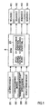
- Fig. 3 is an engagement chart showing a relation between engagement and release of engagement elements on one hand and speed-change stages achieved by the gear train on the other hand.
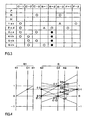
- Fig. 4 is a speed diagram of the gear train.
- Fig. 5 is a hydraulic circuit diagram of an operational system of the control apparatus.
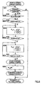
- Fig. 6 is a flowchart of release control of a B-1 brake during a 6-3 speed-change operation.
- Fig. 7 is a flowchart of engagement control of a C-1 brake during the 6-3 speed-change operation.
- Fig. 8 is a flowchart of release control of a C-2 clutch during the 6-3 speed-change operation.
- Fig. 9 is a flowchart for setting a target rotational acceleration during the 6-3 speed-change operation.
- Fig. 10 is a hydraulic-pressure characteristic diagram showing a method of setting a safety factor for a hydraulic pressure for releasing the C-2 clutch.
- Fig. 11 is a flowchart of engagement control of a C-3 clutch during the 6-3 speed-change operation.
- Fig. 12 is a time chart showing how a relation of control among the respective engagement elements during the 6-3 speed-change operation is related to the proceeding of the speed-change operation.
- Fig. 13 is a time chart showing how a relation of control among the respective engagement elements in the case where target rotational acceleration control is not performed during the 6-3 speed-change operation is related to the proceeding of the speed-change operation.
- Fig. 1 is a block diagram of a configuration of a signal system of a control apparatus.
- this control apparatus has an electronic control unit (ECU) 2, which is a central component member of the control apparatus.
- the control apparatus has various sensors as an input means for inputting various pieces of information to the ECU 2, namely, an engine (E/G) speed sensor 31 for detecting an engine speed of a vehicle, a throttle opening sensor 32 for detecting an engine load, a transmission input-shaft speed sensor 33 for detecting an input speed of a transmission, and a vehicle speed sensor 34 for detecting a vehicle speed from a speed of an output shaft of the transmission.
- E/G engine
- E/G engine
- throttle opening sensor 32 for detecting an engine load
- a transmission input-shaft speed sensor 33 for detecting an input speed of a transmission
- vehicle speed sensor 34 for detecting a vehicle speed from a speed of an output shaft of the transmission.
- the control apparatus has a plurality of solenoids as an output means operating by the output of a drive signal based on control information, namely, solenoids 1 to 4 as actuators for solenoid valves 41 to 44 disposed in a hydraulic control unit, which will be described later in detail with reference to Fig. 5.
- Fig. 2 is a skeleton diagram showing a six-speed gear train for FR vehicles as an example of a speed-change mechanism controlled by the aforementioned control apparatus.
- This gear train is composed of a torque converter 7 and a speed-change mechanism.
- the torque converter 7 is equipped with a lock-up clutch.
- the speed-change mechanism has six forward stages and one backward stage and is composed of a planetary gear set G of Ravigneaux type and a deceleration gear G1 of simple planetary type.
- the planetary gear set G which is a main component member of the speed-change mechanism, is constructed of a gear set of Ravigneaux type.
- the gear set is composed of sun gears S2, S3 having different diameters, a ring gear R2, a long pinion gear P2 that meshes with the large-diameter sun gear S2 in a circumscribed manner and that meshes with the ring gear R2 in an inscribed manner, a short pinion gear P3 that meshes with the small-diameter sun gear S3 in a circumscribed manner and that also meshes with the long pinion gear P2 in a circumscribed manner, and a carrier C2 supporting both the pinion gears P2, P3.
- the small-diameter sun gear S3 of the planetary gear set G is coupled to a multiple-disc clutch (C-1) (Hereinafter, each engagement element is marked with a symbol, which precedes the name of the element.).
- the large-diameter sun gear S2 is coupled to a multi-disc C-3 clutch and can be hooked to an automatic transmission case 10 by a B-1 brake constructed of a band brake. Furthermore, the large-diameter sun gear S2 can be hooked to the automatic transmission case 10 by a multiple-disc B-2 brake and an F-1 one-way clutch, which are disposed in parallel with the B-1 brake.
- the carrier C2 is coupled to an input shaft 11 via a C-2 clutch as a multiple-disc engagement element, and can be hooked to the transmission case 10 by a multiple-disc B-3 brake. Also, the carrier C2 can be hooked to the transmission case 10 by an F-2 one-way clutch in such a manner as to rotate in one direction.
- the ring gear R2 is coupled to an output shaft 19.
- the deceleration planetary gear G1 is constructed of a simple planetary gear.
- a ring gear R1 as an input element of the deceleration planetary gear G1 is coupled to the input shaft 11.
- a carrier C1 as an output element of the deceleration planetary gear G1 is coupled to the small-diameter sun gear S3 via the C-1 clutch and to the large-diameter sun gear S2 via the C-3 clutch.
- a sun gear S1 as a stationary element for gaining a counterforce is fixed to the transmission case 10.
- Fig. 3 is an engagement chart showing how speed-change stages to be established are related to engagement and release of the engagement elements of this automatic transmission, that is, the clutches, the brakes, and the one-way clutches.
- each blank filled in with O, each unfilled blank, each blank filled in with ⁇ , and each blank filled in with • represent engagement, release, engagement for engine braking, and engagement that does not directly affect establishment of a speed-change stage, respectively.
- Fig. 4 is a speed diagram showing how speed-change stages established through engagement of each of the clutches, brakes, and one-way clutches (Engagement is denoted by •.) are related to speed ratios among the speed-change elements.
- a first-speed (1st) stage is established through engagement of the C-1 clutch and the B-3 brake (Automatic engagement of the F-2 one-way clutch is adopted instead of engagement of the B-3 brake as is apparent from an operational chart in this embodiment.
- Engagement of the F-2 one-way clutch is adopted as the equivalent of engagement of the B-3 brake because the F-1 one-way clutch for automatically releasing an engaging force upon engagement of the B-1 brake is used to avoid complication of hydraulic pressure control for changeover between the B-3 brake and the B-1 brake during a 1-2 speed-change operation that will be described later and to simplify release control of the B-3 brake.).
- rotation that has been transmitted from the input shaft 11 via the deceleration planetary gear G1 while being decelerated is input to the small-diameter sun gear S3 via the C-1 clutch, gains a counterforce from the carrier C2 that has been hooked through engagement of the F-2 one-way clutch, and is output to the output shaft 19 as decelerated rotation of the ring gear R2 at a maximum deceleration ratio.
- a second-speed (2nd) stage is then established through engagement of the F-1 one-way clutch and engagement of the B-2 brake, which makes engagement of the F-1 one-way clutch effective.
- Engagement of the F-1 one-way clutch and the B-2 brake is equivalent to engagement of the C-1 clutch and the B-1 brake (It will be described later in detail why engagement of the F-1 one-way clutch and the B-2 brake is equivalent to engagement of the C-1 clutch and the B-1 brake.).
- a third-speed (3rd) stage is established through simultaneous engagement of the C-1 clutch and the C-3 clutch.
- rotation that has been transmitted from the input shaft 11 via the deceleration planetary gear G1 while being decelerated is simultaneously input to the large-diameter sun gear S2 and the small-diameter sun gear S3 via the C-1 clutch and the C-3 clutch respectively, so that the planetary gear set G assumes a direct-coupled state. Therefore, rotation of the ring gear R2, which is the same as rotation that has been input to both the sun gears, is output to the output shaft 19 as rotation that has been decelerated with respect to rotation of the input shaft 11.
- a fourth-speed (4th) stage is established through simultaneous engagement of the C-1 clutch and the C-2 clutch.
- rotation that has been transmitted from the input shaft 11 via the deceleration planetary gear G1 while being decelerated is input to the small-diameter sun gear S3 via the C-1 clutch
- non-decelerated rotation that has been input from the input shaft 11 via the C-2 clutch is input to the carrier C2.
- Intermediate rotation between the two input rotations is output to the output shaft 19 as rotation of the ring gear R2, which has been slightly decelerated with respect to rotation of the input shaft 11.
- a fifth-speed (5th) stage is then established through simultaneous engagement of the C-2 clutch and the C-3 clutch.
- rotation that has been transmitted from the input shaft 11 via the deceleration planetary gear G1 while being decelerated is input to the large-diameter sun gear S2 via the C-3 clutch
- non-decelerated rotation that has been input from the input shaft 11 via the C-2 clutch is input to the carrier C2.
- Rotation of the ring gear R2 which has been slightly accelerated with respect to rotation of the input shaft 11, is output to the output shaft 19.
- a sixth-speed (6th) stage is then established through engagement of the C-2 clutch and the B-1 brake.
- non-decelerated rotation is input only to the carrier C2 from the input shaft 11 via the C-2 clutch, gains a counterforce from the sun gear S2 that has been hooked through engagement of the B-1 brake, and is output to the output shaft 19 as further accelerated rotation of the ring gear R2.
- a backward (R) stage is established through engagement of the C-3 clutch and the B-3 brake.
- rotation that has been transmitted from the input shaft 11 via the deceleration planetary gear G1 while being decelerated is input to the large-diameter sun gear S2 via the C-3 clutch, gains a counterforce from the carrier C2 that has been hooked through engagement of the B-3 brake, and is output to the output shaft 19 as reverse rotation of the ring gear R2.
- the F-1 one-way clutch is related to the B-1 brake and the B-2 brake.
- the F-1 one-way clutch coupled to the sun gear S2 is engaged in such a direction as to support a counter torque of the large-diameter sun gear S2 at the second-speed stage, whereby the F-1 one-way clutch can substantially perform the same function as engagement of the B-1 brake.
- the large-diameter sun gear S2 is different from the carrier C2 and is a speed-change element that not only is engaged to achieve the effect of engine braking at the second-speed stage but also is hooked to establish the sixth-speed stage, the B-1 brake is required.
- the large-diameter sun gear S2 rotates reversely with respect to a direction of input rotation upon establishment of the first-speed (1st) stage, but rotates in the direction of input rotation at the third-speed stage or any higher speed stage. Accordingly, the F-1 one-way clutch cannot be directly coupled to a stationary member and thus is disposed in series with the B-2 brake so as to make it possible to control the effectiveness of an engaged state.
- each speed-change stage established as described above is relatively equidistant from its adjacent speed-change stages, so that good speed steps are obtained.
- This gear train does not require multiple changeover of the engagement elements during a normal upshift or downshift operation between two adjacent speed-change stages but requires it during a skip speed-change operation.
- Such a skip speed-change operation is necessary especially during a downshift operation such as a 6-3 or 5-2 speed-change operation (During this speed-change operation, the B-2 brake is always engaged at the second-speed stage or any higher speed stage for the sake of simplification of control. Therefore, automatic engagement of the F-1 one-way clutch plays the same role as engagement of the B-1 brake.).
- the hydraulic control unit for controlling the speed-change mechanism thus constructed by operating hydraulic servos for the aforementioned clutches and brakes is designed such that each of the hydraulic servos for a corresponding one of the engagement elements is controlled directly and independently by a proper solenoid valve on the basis of a solenoid drive signal from the electronic control unit 2 so as to make the aforementioned skip speed-change operation easy to perform.
- this hydraulic circuit is constructed as follows.
- control valves 45 to 48 are connected in parallel with one another with respect to a line-pressure hydraulic passage 51, which is connected to a circuit for supplying a line pressure (a maximum pressure allowing the engagement elements to be maintained in an engaged state in accordance with a running load of the vehicle).
- Fig. 5 indicates this circuit as a block instead of showing its concrete construction.
- Each of the control valves 45 to 48 operates for pressure regulation in accordance with a solenoid pressure applied from a corresponding one of solenoid valves 41 to 44.
- a hydraulic servo 61 for the C-1 clutch is connected to the line-pressure hydraulic passage 51 via a C-1 control valve 45, which is connected at its spool end to a hydraulic passage 52 for a solenoid modulator pressure (a hydraulic pressure that is obtained by reducing a line pressure via a modulator valve so as to increase a gain of pressure regulation by a solenoid valve).
- the C-1 control valve 45 is designed as a spool valve having lands at its opposed ends, and the lands are different in diameter.
- the C-1 control valve 45 is constructed such that a solenoid signal pressure is applied to the large-diameter land end against a spring load applied to the small-diameter land end, that the large-diameter land thereby closes a drain port, that the line-pressure hydraulic passage 51 and the hydraulic servo 61 thereby communicate with each other while the small-diameter land narrows a gap between an inlet port leading to the line-pressure hydraulic passage 51 and an outlet port leading to the hydraulic servo 61, that the small-diameter land closes the inlet port and the large-diameter land opens the drain port as soon as a solenoid pressure is released, and that the hydraulic servo 61 is connected in a drainable manner as a result.
- the solenoid valve 41 is designed as a normal-open linear solenoid valve. Similarly, the solenoid valve 41 is constructed such that a gap between the solenoid-modulator- pressure hydraulic passage 52 and a solenoid-pressure hydraulic passage 53 is adjusted by a load applied to a plunger against a spring load applied to one end of a spool having lands at its opposed ends and that a solenoid pressure is regulated by adjusting an amount of drainage through the solenoid-pressure hydraulic passage 53.
- the C-2 clutch, the B-1 brake, and the C-3 clutch also adopt a parallel circuit construction that is quite similarly composed of the control valves 46, 47, 48, the solenoid valves 42, 43, 44, and solenoid-pressure hydraulic passages 54, 55, 56, respectively.
- the solenoid-pressure hydraulic passages 54, 55, 56 connect the control valves 46, 47, 48 to the solenoid valves 42, 43, 44, respectively.
- the automatic transmission thus constructed requires operation of four engagement elements (the C-1 clutch, the C-2 clutch, the C-3 clutch, and the B-1 brake), for example, during a 6-3 speed-change operation wherein the first speed-change stage is the sixth-speed stage and wherein the second speed-change stage is the third-speed stage that is apart from the sixth-speed stage by three stages.
- the first speed-change stage (the sixth-speed stage) is established through engagement of the first and second engagement elements (the B-1 brake and the C-2 brake), and the second speed-change stage is established through engagement of the third and fourth engagement elements (the C-1 clutch and the C-3 clutch).
- the first speed-change stage is the fifth-speed stage
- operation of four engagement elements (the C-1 clutch, the C-2 clutch, the C-3 clutch, and the F-1 one-way clutch) is also required during a speed-change operation from the fifth-speed stage to the second-speed stage that is apart from the fifth-speed stage by three stages.
- the first, second, third, and fourth engagement elements are the C-2 clutch, the C-3 clutch, the C-1 clutch, and the F-1 one-way clutch, respectively.
- the speed-change control unit is provided with the speed-change control means 21 (see Fig.
- engagement or release of the engagement elements includes a transient slip state leading to complete engagement or complete release. Accordingly, starting to release a certain engagement element means starting to cause it to slip. As regards an engagement element that is operated hydraulically, starting to release it means starting to cause it to slip through a decrease in engaging force. As regards a one-way clutch that is not operated hydraulically, starting to release it means making it free in accordance with a change in rotational direction of a rotational member. Similarly, completing engagement of a certain engagement element means causing it to stop slipping.
- the speed-change control means 21 is designed such that the first speed-change stage (the sixth-speed stage or the fifth-speed stage) is established through operation of two (the C-1 clutch and the B-1 brake) of the aforementioned four engagement elements, that the second speed-change stage (the third-speed stage or the second-speed stage) is established through operation of the other two engagement elements, that a third speed-change stage (the fourth-speed stage or the third-speed stage) is set, and that a speed-change operation from the first speed-change stage (the sixth-speed stage or the fifth-speed stage) to the second speed-change stage (the third-speed stage or the second-speed stage) is shifted to a speed-change operation from the third speed-change stage (the fourth-speed stage or the third-speed stage) to the second speed-change stage (the third-speed stage or the second-speed stage) via a speed-change operation from the first speed-change stage (the sixth-speed stage or the fifth-speed stage) to the third speed-change stage (the fourth-speed stage or the fourth-speed
- the four engagement elements are the C-1 clutch that is engaged during a speed-change operation to the third speed-change stage (the fourth-speed stage or the third-speed stage), the B-1 brake or the C-2 clutch that is released during the speed-change operation, the C-3 clutch or the F-1 one-way clutch that is engaged during a speed-change operation to the second speed-change stage (the third-speed stage or the second-speed stage), and the C-2 clutch or the C-3 clutch that is released during the speed-change operation.
- the speed-change control means 21 of this embodiment is constructed as a program in the control unit.
- the speed-change operation is performed by controlling the hydraulic servos 61 to 64 for the engagement elements through operation of the solenoid valve 42 caused by a solenoid drive signal, which is output on the basis of the program.
- control flowcharts of the speed-change control means 21 for the engagement elements will be described one by one.
- This processing is intended to prevent the engine from undergoing prefiring due to operational dispersion in the C-1 clutch resulting from aging or a difference among individual transmissions.
- a period for maintaining this predetermined pressure is then monitored in step S13. The processing is continued until the result of the determination (timer t > t_wait) in step S13 becomes positive.
- a processing of gradually reducing the servo hydraulic pressure (sweep-down with a gradient of dP B1 C, feedback control) is then performed in step S15.
- a determination on a proceeding degree (ShiftR) of the speed-change operation is then made in step S16.
- this hydraulic-pressure control processing is designed to control an electric current value of a drive signal transmitted to a solenoid 3 shown in Fig. 1 and operate the solenoid valve 43 shown in Fig.
- the proceeding degree (ShiftR) of the speed-change operation is calculated on the basis of values detected by the transmission input-shaft speed sensor 33 and the vehicle speed sensor 34 shown in Fig. 1. For instance, a comparative value (S_End2) used in this determination is set as 70%. Because the result of this determination is negative (No) at the outset, a loop for returning to step S15 is repeated. If the result of the determination on the proceeding degree of the speed-change operation in step S16 becomes positive (ShiftR > S_End2), a low-pressure processing of completely removing the servo hydraulic pressure of the B-1 brake (sweep-down with a gradient of dP B1 d) is then performed in step S17. This processing is completed automatically as soon as a solenoid valve 3 reaches a full output. Therefore, the 6-4 speed-change control for releasing the B-1 brake is terminated without performing any further monitoring or determining operation.
- FIG. 7 A control flowchart for engaging the C-1 clutch or the third engagement element is shown in Fig. 7.
- a servo activation control sub-routine processing is then performed in step S22.
- This processing is designed to maintain a fast fill of a hydraulic pressure for filling a hydraulic servo cylinder for the C-1 clutch and a subsequent piston stroke pressure for narrowing a gap between a hydraulic servo piston and a frictional member of the engagement element.
- This processing is a known processing that is usually performed to engage a clutch.
- a determination on a proceeding degree as an indicator (Shift R) for making a determination on a proceeding degree of a speed-change operation is made (ShiftR > S_End1) in step S23.
- a comparative value (S_End1) used in this case is set as 70%. Because the result of this determination is negative (No) at the outset, the processing for this determination is continued until the proceeding of the speed-change operation is completed. As soon as the result of the aforementioned determination becomes positive (Yes), a pressure-increasing operation for starting engagement of the C-1 clutch (sweep-up with a gradient of dP C1 a) is started in step S24. In step S25, while this pressure-increasing operation is continued, it is determined whether or not the proceeding degree (ShiftR) of the speed-change operation has reached a state prior to synchronization with the fourth-speed stage, for example, 90% (ShiftR > S_End2).
- step S25 a processing of increasing the servo hydraulic pressure to a line pressure (sweep-up with a gradient of dP C1 b) is performed in step S26 so as to reliably maintain engagement of the C-1 clutch.
- a processing of determining whether or not the servo hydraulic pressure has reached the line pressure (P C1 > P FULL ) is then repeated in step S27. As soon as the result of the determination in step S27 becomes positive, the 6-4 speed-change control for engagement control of the C-1 clutch is terminated.
- FIG. 8 A control flowchart for releasing the C-2 clutch or the second engagement element is shown in Fig. 8.
- step S31 it is determined first in step S31 whether or not the 6-4 speed-change operation has been terminated. If the result of the determination in step S31 is positive, subsequent processings are skipped to terminate the C-2 release control. While the aforementioned case is excluded, it is then determined in step S32 whether or not a shift command to the third-speed stage is fulfilled (3rd determination). Thus, a shift operation to the third-speed stage is distinguished from shift operations to the other speed-change stages.
- a determination on a proceeding degree (ShiftR) of the speed-change operation is started in step S33 so as to determine a timing for starting to release the C-2 clutch.
- An indicator for making a determination on a proceeding degree of the speed-change operation in this case is a value (ShiftR_S1) that is based on a speed of the input shaft of the transmission.
- f 1 () represents a C-2 clutch pressure required for an input torque in a state of the sixth-speed stage
- f 2 () represents a C-2 clutch pressure correction amount required for maintaining the state of the sixth-speed stage without causing the C-2 clutch to slip in response to a change in a B-1 brake pressure
- f 3 () represents a C-2 clutch pressure correction amount corresponding to a change in a C-2 clutch quotient torque generated in response to a change in a C-1 clutch pressure
- each of ⁇ , ⁇ , and ⁇ represents a gain used in calculating a corresponding one of the hydraulic pressures.
- step S35 a determination on a proceeding degree (ShiftR) of the speed-change operation is then made (ShiftR > S_End3) in step S35 so as to determine whether or not there is a state prior to synchronization with the fourth-speed stage.
- Fig. 9 is a flowchart for setting the target rotational acceleration ⁇ 0 corresponding to the proceeding degree of the speed-change operation.
- it is determined first in step S41 whether or not the 6-4 speed-change operation is proceeding. On the premise that the 6-4 speed-change operation is proceeding, it is then determined in step S42 whether or not a 6-3 speed-change command has been issued at this stage.
- Target_ ⁇ 64 represents a target rotational acceleration for the 6-4 speed-change operation.
- the target rotational acceleration ⁇ 0 is determined on the basis of the input rotational acceleration (_inSp) substantially in the first half of the 6-4 speed-change operation and is set as the constant value (Target_ ⁇ 64 ) substantially in the second half of the 6-4 speed-change operation.
- the aforementioned input torque can be calculated by calculating an engine torque from a map defining a relation between throttle opening and engine speed, calculating a speed ratio from input and output speeds of the torque converter, and multiplying the engine torque by the speed ratio.
- the input torque is then converted into a hydraulic pressure by dividing the input torque by a product of a pressure-receiving area of the piston of the hydraulic servo of a corresponding one of the engagement elements, the number of frictional members, an effective radius, and a friction coefficient, and adding a piston stroke pressure to the quotient.
- step S37 a determination on a proceeding degree (ShiftR) of the speed-change operation is continued (ShiftR > S_End2) in step S37. As soon as the result of the determination in step S37 becomes positive, the fourth-speed stage is established completely. Thus, the 4-3 speed-change control is then performed (The 4-3 speed-change control is started.).
- a low-pressure processing (sweep-down with a gradient of dP C2 d) is performed to completely remove the servo hydraulic pressure applied to the C-2 clutch. Because this processing is also completed automatically as soon as the solenoid valve 2 reaches a full output, the 4-3 speed-change control for releasing the C-2 clutch is terminated without performing any particular monitoring or determining operation. Thus, the C-2 release control is terminated.
- FIG. 11 A control flowchart for engaging the C-3 clutch or the fourth engagement element is shown in Fig. 11.
- This control is substantially identical to the aforementioned engagement control of the C-1 clutch, although they are started at different timings.
- a servo activation control sub-routine processing is then performed in step S52.
- This processing is designed to maintain a fast fill of a hydraulic pressure for filling a hydraulic servo cylinder for the C-3 clutch and a subsequent piston stroke pressure for narrowing a gap between a hydraulic servo piston and a frictional member of the engagement element.
- This processing is a known processing that is usually performed to engage a clutch.
- a determination on a proceeding degree as an indicator (ShiftR) for making a determination on a proceeding degree of a speed-change operation is made (ShiftR > S_End1) in step S53.
- the proceeding degree (ShiftR) of the speed-change operation has already been described above. Because the result of this determination is negative (No) at the outset, the processing for this determination is continued until the proceeding of the speed-change operation is completed.
- a pressure-increasing operation for starting engagement of the C-3 clutch (sweep-up with a gradient of dP C3 a) is started in step S54.
- step S55 while this pressure-increasing operation is continued, it is determined whether or not the proceeding degree (ShiftR) of the speed-change operation has reached synchronization with the third speed stage (ShiftR > S_End2). Because the result of this determination is also negative at the outset, the sweep-up operation is continued through repetition of a loop for returning to step S54 until the proceeding of the speed-change operation is completed. If the result of the determination in step S55 becomes positive, a processing of increasing the servo hydraulic pressure to a line pressure (sweep-up with a gradient of dP C3 b) is performed in step S56 so as to reliably maintain engagement of the C-3 clutch.
- step S57 A processing of determining whether or not the servo hydraulic pressure has reached the line pressure (P C1 > P FULL ) is then repeated in step S57. As soon as the result of the determination in step S57 becomes positive, the 4-3 speed-change control for engagement control of the C-3 clutch is terminated.
- Fig. 12 is a time chart showing how the operations of the four engagement elements are related to the speed of the input shaft, the rotational acceleration (_inSp) of the input shaft, the target rotational acceleration ( ⁇ 0 ), and the input torque (t 0 ).
- the servo hydraulic pressure P B-1 of the B-1 brake is first set temporarily as a low pressure slightly lower than a line pressure, immediately whereafter engagement control of the C-1 clutch is started so that the servo hydraulic pressure P C-1 of the C-1 clutch is increased to a fast-fill pressure.
- the servo hydraulic pressure P B-1 of the B-1 brake is reduced to a predetermined pressure P B1 C at the beginning of the sweep-down operation, and the servo hydraulic pressure P C-1 of the C-1 clutch is reduced to an initial pressure at the beginning of the sweep-up operation.
- the servo hydraulic pressure P B-1 of the B-1 brake is reduced with a constant gradient dP B1 through feedback control, and the servo hydraulic pressure P C-1 of the C-1 clutch is increased with a constant gradient dP C1 a.
- the B-1 brake starts to slip, whereby the sun gears S3, S2 proceed in directions of deceleration and acceleration respectively with respect to a point of engagement of the C-2 clutch that is in engagement.
- the rotational-element side of the B-1 brake starts to rotate positively from a hooked state corresponding to 0.
- the output-element side of the C-3 clutch the output-element side is accelerated from negative rotation on the output-element side with respect to decelerated rotation on the input-element side, and proceeds toward positive rotation.
- the C-1 clutch is decelerated in the same direction as and at the same speed as rotation of the engine from a state of positive rotation that has been substantially accelerated with respect to rotation of the engine.
- the servo hydraulic pressure P C-2 of the C-2 clutch is reduced at a stretch to such a hydraulic pressure that release (slip) of the C-2 clutch is not caused.
- the servo hydraulic pressure of the C-2 clutch is then gradually reduced through a control operation based on the target rotational acceleration ⁇ 0 corresponding to the input rotational acceleration (_inSp indicated by a broken line in Fig. 12).
- the 6-4 speed-change operation proceeds toward synchronization with the fourth-speed stage.
- the servo hydraulic pressure of the C-2 clutch during descent control is controlled through the reduction control in such a manner as to become a hydraulic pressure suited to reach a state prior to the start of release when it is determined that a state prior to synchronization with the fourth-speed stage has been achieved (S_End3). Therefore, at this stage, the second-stage control operation of controlling the target rotational acceleration ⁇ 0 on the basis of the constant value (Target_ ⁇ 64 ) of the target rotational acceleration during the 6-4 speed-change operation is started. Due to this control operation, the torque t 2 for holding the C-2 clutch is held at a constant value in a state corresponding to the start of slip. On the gear train, at this moment, the C-2 clutch starts to slip and rotates negatively.
- the C-1 clutch that has been decelerated in a state of deceleration of slip from a state of deceleration of release proceeds toward null rotation of engagement. Meanwhile, the speed of the C-3 clutch continues to increase. If it is determined that the servo hydraulic pressure P C-1 of the C-1 clutch has reached the line pressure, engagement control of the C-3 clutch is started. Thereby, after reaching a peak upon synchronization with the fourth-speed stage (4th 100%), the speed of the C-3 clutch starts to decrease. The C-3 clutch then passes through a state of slip-based deceleration and proceeds toward a state of null rotation of complete engagement.
- the hydraulic-pressure control that is performed in accordance with the proceeding of engagement of the C-3 clutch is identical to the control in the case of the C-1 clutch, except that a determination on the proceeding degree of 70% or a state prior to synchronization is made on the basis of the third-speed stage instead of the fourth-speed stage. If synchronization with the third-speed stage is then achieved due to the proceeding of the 4-3 speed-change operation, the servo hydraulic pressure P C-2 of the C-2 clutch is released completely, and the servo hydraulic pressure P C-3 of the C-3 clutch is increased to a line pressure due to a full output.
- the 6-3 speed-change operation is realized in a successive manner, namely, in the form of 6-4-3 speed-change operations.
- Fig. 13 is a time chart showing a 6-3 speed-change operation that is performed irrespective of the setting of the target rotational acceleration (Target_ ⁇ 64 ), in contrast with the aforementioned 6-3 speed-change operation.
- the rotational acceleration of the input shaft falls, for example, due to an increase in the pressure applied to the B-1 brake, whereby the torque t 1 (indicated by a broken line in Fig. 13) for holding the C-2 clutch recovers to the input torque t 0 .
- the C-2 clutch that has temporarily assumed a state of slip is engaged again, and the timing for starting the 4-3 speed-change operation is delayed, or the input speed increases bluntly at the beginning of the 4-3 speed-change operation.
- the timing for substantially completing the 4-3 speed-change operation namely, the timing for interchanging release of the C-2 clutch with engagement of the C-1 clutch is retarded substantially. It is apparent from changes in the speed of the input shaft shown in the time chart of Fig. 12 that this period has been shortened substantially. In this manner, the period for the 6-3 speed-change operation can be shortened by setting the target rotational acceleration (Target_ ⁇ 64 ).
- the speed-change control is performed in a similar manner as to the case of the 5-2 speed-change operation as well, except that the engagement elements to be controlled are replaced.
- the first engagement element, the second engagement element, and the third engagement element are the C-2 clutch, the C-3 clutch, and the C-1 clutch, respectively.
- this gear train is specially designed in that the second-speed stage is established through engagement (lock) of the F-1 one-way clutch as the fourth engagement element instead of engagement of the B-1 brake. Therefore, unlike the case of the 6-3 speed-change operation, hydraulic-pressure control for engaging the B-1 brake in the second speed-change stage (the 3-2 speed-change operation) is unnecessary. As a result, simplification of control is achieved accordingly.
- the larger one of the rotational acceleration (_inpSp) of the input shaft and the target rotational acceleration (Target_ ⁇ 64 ) for the 6-4 speed-change operation is selected as the target rotational acceleration ⁇ 0 in the initial period of the speed-change operation, and Target_ ⁇ 64 is selected if the proceeding degree of the speed-change operation exceeds S_End afterwards.
- the present invention has been described in detail while referring to its embodiment regarding the specific gear train.
- the concept of the present invention is not to be limited to the gear train shown as an example.
- the present invention is applicable to all the gear trains wherein a relation of engagement and release among engagement elements in a speed-change operation to which four engagement elements are related is established by simultaneously changing over the four elements.
- the present invention has been made to eliminate a feeling of two-phase speed-change operations by causing a speed-change operation to proceed continuously when the speed-change operation is performed through two-phase control of engagement and release of four engagement elements.
- the present invention provides a control apparatus for an automatic transmission wherein a predetermined speed-change operation is achieved through a pre-phase speed-change operation in which a first engagement element and a third engagement element are released and engaged respectively and through a post-phase speed-change operation in which a second engagement element and a fourth engagement element are released and engaged respectively.
- the control apparatus sets a target rotational acceleration of an input shaft of the transmission, and controls release of the second engagement element for a transition to the post-phase speed-change operation in accordance with the target rotational acceleration.
- the input speed during the transition from the pre-phase speed-change operation to the post-phase speed-change operation changes continuously, so that bluntness is prevented from being caused between the pre-stage and post-stage speed-change operations.
Abstract
Description
Intermediate rotation between the two input rotations is output to the
- 21
- speed-change control means (6-4 speed-change operation, 5-2 speed-change operation,...)
- 31
- E/G speed sensor
- 32
- throttle opening sensor
- 33
- transmission input-shaft speed sensor
- 34
- vehicle speed sensor
- 41
-
solenoid 1 - 42
-
solenoid 2 - 43
-
solenoid 3 - 44
-
solenoid 4
- (1)
- solenoid modulator pressure
- (2)
- line pressure
- (1)
- start 6-4 speed-change control
- (2)
- terminate 6-4 speed-change control
- S11
- start timer t=0
- S15
- sweep down with gradient of dPB1C, feedback control
- S17
- sweep down with gradient of dPB1d
- (1)
- start 6-4 speed-change control
- (2)
- terminate 6-4 speed-change control
- S21
- start timer t=0
- S22
- servo activation control
- S24
- sweep up with gradient of dPC1a
- S26
- sweep up with gradient of dPC1b
- (1)
- start 6-4 speed-change control
- (2)
- start 4-3 speed-change control
- (3)
- terminate 4-3 speed-change control
- (4)
- terminate C-2 release control
- S31
- terminate 6-4 speed-change operation
- S32
- 3rd determination
- S38
- sweep down with gradient of dPC2d
- (1)
- start 6-4 speed-change control
- (2)
- terminate 6-4 speed-change control
- S41
- terminate 6-4 speed-change operation
- S42
- 3rd determination
- (1)
- start 4-3 speed-change control
- (2)
- terminate 4-3 speed-change control
- S51
- start timer t=0
- S52
- servo activation control
- S54
- sweep up with gradient of dPC3a
- S56
- sweep up with gradient of dPC3b
- (1)
- input torque
- (2)
- rotational acceleration
- (3)
- speed of input shaft
- (4)
- servo hydraulic pressure
- (5)
- torque t2 for holding C-2
- (6)
- _inSp (rotational acceleration)
- (1)
- input torque
- (2)
- rotational acceleration
- (3)
- speed of input shaft
- (4)
- servo hydraulic pressure
- (5)
- torque t1 for holding C-2
- (6)
- _inSp (rotational acceleration)
Claims (20)
- A control apparatus for an automatic transmission wherein operation of four engagement elements is required at the time of a speed-change operation from a first speed-change stage to a second speed-change stage, wherein the first speed-change stage is established through engagement of a first engagement element and a second engagement element, and wherein a second speed-change stage is established through engagement of a third engagement element and a fourth engagement element, comprising:speed-change control means for controlling a state prior to the start of release of the second engagement element in accordance with a predetermined target rotational acceleration.
- The control apparatus according to claim 1, whereinthe target rotational acceleration is set in accordance with a rotational acceleration of an input shaft at the time when the first engagement element is released.
- The control apparatus according to claim 1, whereinthe second engagement element is controlled by a hydraulic pressure of a hydraulic servo for the second engagement element, andthe hydraulic pressure is controlled in accordance with a rotational acceleration of the input shaft and a target rotational acceleration, and is determined by switching over the rotational acceleration of the input shaft and the target rotational acceleration.
- The control apparatus according to claim 3, whereinthe hydraulic pressure of the hydraulic servo for the second engagement element is determined on the basis of the smaller one of the rotational acceleration of the input shaft and the target rotational acceleration.
- The control apparatus according to claim 3, whereinthe hydraulic pressure of the second engagement element is determined on the basis of the target rotational acceleration if the proceeding degree of a speed-change operation resulting from release of the first engagement element exceeds a predetermined value.
- The control apparatus according to claim 5, whereinthe hydraulic pressure of the hydraulic servo for maintaining engagement of the second engagement element until it is released is set as a minimum hydraulic pressure required for maintaining the first speed-change stage, on the basis of the rotational acceleration of the input shaft or the target rotational acceleration.
- The control apparatus according to claim 6, whereinthe hydraulic pressure of the hydraulic servo for the second engagement element is set as a predetermined guard hydraulic pressure if the determined hydraulic pressure has become lower than the guard pressure.
- The control apparatus according to claim 7, whereinthe guard hydraulic pressure is a minimum hydraulic pressure allowing engagement of the second engagement element to be maintained.
- The control apparatus according to claim 3, whereinthe hydraulic pressure of the hydraulic servo for the second engagement element is determined on the basis of the rotational acceleration of the input shaft until the rotational acceleration of the input shaft exceeds the target rotational acceleration, and is determined on the basis of the target rotational acceleration after the rotational acceleration of the input shaft has exceeded the target rotational acceleration.
- The control apparatus according to claim 9, whereinthe hydraulic pressure of the hydraulic servo for maintaining engagement of the second engagement element until it is released is set as a minimum hydraulic pressure required for maintaining the first speed-change stage, on the basis of the rotational acceleration of the input shaft or the target rotational acceleration.
- The control apparatus according to claim 10, whereinthe hydraulic pressure of the hydraulic servo for the second engagement element is set as a predetermined guard hydraulic pressure if the determined hydraulic pressure has become lower than the guard pressure.
- The control apparatus according to claim 11, whereinthe guard hydraulic pressure is a minimum hydraulic pressure allowing engagement of the second engagement element to be maintained.
- The control apparatus according to claim 3, whereinthe hydraulic pressure of the hydraulic servo for the second engagement element is determined in accordance with an input torque and an inertia torque that occurs in a drive system and that is calculated on the basis of the rotational acceleration of the input shaft and the target rotational acceleration.
- The control apparatus according to claim 1, whereinthe speed-change control means performs control such that release of the second engagement element is started after release of the first engagement element has been started and that engagement of the fourth engagement element is completed after engagement of the third engagement element has been completed.
- The control apparatus according to claim 14, whereinthe speed-change control means performs control for starting to release the second engagement element before engagement of the third engagement element is completed.
- The control apparatus according to claim 1, whereinthe speed-change control means releases the first engagement element, and starts control for releasing the second engagement element during control for engaging the third engagement element.
- The control apparatus according to claim 16, whereinthe automatic transmission establishes the first speed-change stage by engaging the first engagement element and the second engagement element, establishes the second speed-change stage by engaging the third engagement element and the fourth engagement element, and establishes the third speed-change stage by engaging the second engagement element and the third engagement element.
- The control apparatus according to claim 17, whereinthe target rotational acceleration is determined by a target period for a speed-change operation from the first speed-change stage to the third speed-change stage, a gear ratio and an output speed in the first speed-change stage, and a gear ratio and an output speed in the third speed-change stage.
- The control apparatus according to claim 18, whereinthe hydraulic pressure of the second engagement element is determined on the basis of the rotational acceleration of the input shaft substantially in the first half of the speed-change operation from the first speed-change stage to the third speed-change stage, and is determined on the basis of the target rotational acceleration substantially in the second half of the speed-change operation from the first speed-change stage to the third speed-change stage.
- The control apparatus according to claim 1, whereinthe speed-change operation from the first speed-change stage to the second speed-change stage is a kick-down speed-change operation performed by depressing an accelerator pedal.
Applications Claiming Priority (2)
| Application Number | Priority Date | Filing Date | Title |
|---|---|---|---|
| JP2001116175A JP4560985B2 (en) | 2001-04-13 | 2001-04-13 | Shift control device for automatic transmission |
| JP2001116175 | 2001-04-13 |
Publications (3)
| Publication Number | Publication Date |
|---|---|
| EP1249644A2 true EP1249644A2 (en) | 2002-10-16 |
| EP1249644A3 EP1249644A3 (en) | 2009-05-06 |
| EP1249644B1 EP1249644B1 (en) | 2011-01-12 |
Family
ID=18966950
Family Applications (1)
| Application Number | Title | Priority Date | Filing Date |
|---|---|---|---|
| EP02008097A Expired - Lifetime EP1249644B1 (en) | 2001-04-13 | 2002-04-11 | Speed-change control apparatus for automatic transmission |
Country Status (4)
| Country | Link |
|---|---|
| US (1) | US6755767B2 (en) |
| EP (1) | EP1249644B1 (en) |
| JP (1) | JP4560985B2 (en) |
| DE (1) | DE60238882D1 (en) |
Cited By (4)
| Publication number | Priority date | Publication date | Assignee | Title |
|---|---|---|---|---|
| EP1666766A1 (en) * | 2003-09-10 | 2006-06-07 | Aisin AW Co., Ltd. | Automatic transmission for vehicle |
| DE102005058777A1 (en) * | 2005-12-09 | 2007-06-14 | Zf Friedrichshafen Ag | Circuit implementation method for automatic transmission of vehicle, involves performing shifting process to operate special driving function circuits to permit larger changes of translation according to predetermined normal program |
| EP1837560A2 (en) * | 2006-03-20 | 2007-09-26 | AISIN AI Co., Ltd. | Automated manual transmission and method for controlling the same |
| DE10321474B4 (en) * | 2002-05-20 | 2016-03-03 | Aisin Aw Co., Ltd. | Shift control device for automatic transmission |
Families Citing this family (13)
| Publication number | Priority date | Publication date | Assignee | Title |
|---|---|---|---|---|
| JP3901010B2 (en) * | 2002-05-17 | 2007-04-04 | アイシン・エィ・ダブリュ株式会社 | Shift control device for automatic transmission |
| KR100489094B1 (en) | 2002-12-05 | 2005-05-12 | 현대자동차주식회사 | method for controling shift route of six-speed automatic transmission |
| CN100458220C (en) * | 2003-09-10 | 2009-02-04 | 爱信艾达株式会社 | Automatic transmission for vehicle |
| JP4257328B2 (en) * | 2005-12-26 | 2009-04-22 | ジヤトコ株式会社 | Control device for automatic transmission |
| JP4760631B2 (en) | 2006-09-08 | 2011-08-31 | トヨタ自動車株式会社 | Control device for automatic transmission, control method, program for causing computer to realize the method, and recording medium recording the program |
| US8113989B2 (en) | 2008-10-02 | 2012-02-14 | Ford Global Technologies, Llc | Control of sequential downshifts in a transmission |
| KR20110005931A (en) * | 2009-07-13 | 2011-01-20 | 현대자동차주식회사 | Method for reducing gear shifting shock of hybrid electric vehicle |
| JP5477662B2 (en) * | 2010-09-28 | 2014-04-23 | アイシン・エィ・ダブリュ株式会社 | Transmission and transmission control device |
| JP4978727B2 (en) * | 2010-11-15 | 2012-07-18 | トヨタ自動車株式会社 | Control device for automatic transmission, control method, program for causing computer to realize the method, and recording medium recording the program |
| JP6218601B2 (en) * | 2013-12-26 | 2017-10-25 | アイシン・エィ・ダブリュ株式会社 | Control device for automatic transmission |
| KR101734262B1 (en) * | 2015-08-12 | 2017-05-11 | 현대자동차 주식회사 | Apparatus for controlling autotransmission and methof thereof |
| JP6551329B2 (en) * | 2016-07-15 | 2019-07-31 | トヨタ自動車株式会社 | Control device of automatic transmission |
| CN109804184B (en) * | 2016-07-20 | 2020-09-18 | 加特可株式会社 | Control device and control method for automatic transmission |
Citations (2)
| Publication number | Priority date | Publication date | Assignee | Title |
|---|---|---|---|---|
| EP0802353A2 (en) | 1996-04-19 | 1997-10-22 | Aisin Aw Co., Ltd. | Clutch pressure control during skip or overlap shift of an automatic transmission |
| US5697864A (en) | 1995-01-10 | 1997-12-16 | Mitsubishi Denki Kabushiki Kaisha | Shift control apparatus for an automatic transmission |
Family Cites Families (12)
| Publication number | Priority date | Publication date | Assignee | Title |
|---|---|---|---|---|
| JPH0751984B2 (en) * | 1986-04-18 | 1995-06-05 | 三菱自動車工業株式会社 | Shift control system for automatic transmissions for vehicles |
| FR2656055B1 (en) | 1989-12-18 | 1994-04-29 | Lepelletier Pierre | MULTI-SPEED AUTOMATIC TRANSMISSION FOR MOTOR VEHICLE. |
| JP2879861B2 (en) * | 1991-06-14 | 1999-04-05 | 本田技研工業株式会社 | Shift control method for automatic transmission |
| JPH05315898A (en) | 1992-05-13 | 1993-11-26 | Yokogawa Electric Corp | Trigger synchronization circuit |
| US5443427A (en) * | 1992-06-23 | 1995-08-22 | Honda Giken Kogyo Kabushiki Kaisha | Apparatus for controlling automatic transmission |
| JP2990323B2 (en) | 1993-03-22 | 1999-12-13 | 富士ゼロックス株式会社 | Thermal head trimming method and trimming device |
| JPH07243518A (en) * | 1994-03-09 | 1995-09-19 | Unisia Jecs Corp | In-shifting line pressure study control device of automatic transmission of car |
| JP3627276B2 (en) * | 1995-03-16 | 2005-03-09 | アイシン・エィ・ダブリュ株式会社 | Shift control device for automatic transmission |
| JP3269333B2 (en) * | 1995-06-13 | 2002-03-25 | 三菱自動車工業株式会社 | Transmission control device for automatic transmission |
| JPH0989094A (en) * | 1995-09-21 | 1997-03-31 | Toyota Motor Corp | Control device for engine and automatic transmission |
| JPH09269051A (en) * | 1996-03-31 | 1997-10-14 | Mazda Motor Corp | Controller for automatic transmission |
| JP3293455B2 (en) * | 1996-04-04 | 2002-06-17 | アイシン・エィ・ダブリュ株式会社 | Control device for automatic transmission |
-
2001
- 2001-04-13 JP JP2001116175A patent/JP4560985B2/en not_active Expired - Fee Related
-
2002
- 2002-04-11 US US10/119,693 patent/US6755767B2/en not_active Expired - Lifetime
- 2002-04-11 DE DE60238882T patent/DE60238882D1/en not_active Expired - Lifetime
- 2002-04-11 EP EP02008097A patent/EP1249644B1/en not_active Expired - Lifetime
Patent Citations (2)
| Publication number | Priority date | Publication date | Assignee | Title |
|---|---|---|---|---|
| US5697864A (en) | 1995-01-10 | 1997-12-16 | Mitsubishi Denki Kabushiki Kaisha | Shift control apparatus for an automatic transmission |
| EP0802353A2 (en) | 1996-04-19 | 1997-10-22 | Aisin Aw Co., Ltd. | Clutch pressure control during skip or overlap shift of an automatic transmission |
Cited By (8)
| Publication number | Priority date | Publication date | Assignee | Title |
|---|---|---|---|---|
| DE10321474B4 (en) * | 2002-05-20 | 2016-03-03 | Aisin Aw Co., Ltd. | Shift control device for automatic transmission |
| EP1666766A1 (en) * | 2003-09-10 | 2006-06-07 | Aisin AW Co., Ltd. | Automatic transmission for vehicle |
| EP1666766A4 (en) * | 2003-09-10 | 2007-11-07 | Aisin Aw Co | Automatic transmission for vehicle |
| US7462126B2 (en) | 2003-09-10 | 2008-12-09 | Aisin Aw Co., Ltd. | Vehicular automatic transmission |
| DE102005058777A1 (en) * | 2005-12-09 | 2007-06-14 | Zf Friedrichshafen Ag | Circuit implementation method for automatic transmission of vehicle, involves performing shifting process to operate special driving function circuits to permit larger changes of translation according to predetermined normal program |
| DE102005058777B4 (en) * | 2005-12-09 | 2020-09-03 | Zf Friedrichshafen Ag | Method for carrying out shifts in an automatic transmission |
| EP1837560A2 (en) * | 2006-03-20 | 2007-09-26 | AISIN AI Co., Ltd. | Automated manual transmission and method for controlling the same |
| EP1837560A3 (en) * | 2006-03-20 | 2009-04-01 | AISIN AI Co., Ltd. | Automated manual transmission and method for controlling the same |
Also Published As
| Publication number | Publication date |
|---|---|
| DE60238882D1 (en) | 2011-02-24 |
| EP1249644A3 (en) | 2009-05-06 |
| US20020151409A1 (en) | 2002-10-17 |
| JP4560985B2 (en) | 2010-10-13 |
| EP1249644B1 (en) | 2011-01-12 |
| US6755767B2 (en) | 2004-06-29 |
| JP2002310280A (en) | 2002-10-23 |
Similar Documents
| Publication | Publication Date | Title |
|---|---|---|
| EP1096178B1 (en) | Shift control apparatus and method for an automatic transmission | |
| EP1249642B1 (en) | Method and apparatus for controlling an automatic vehicle transmission | |
| EP1249644B1 (en) | Speed-change control apparatus for automatic transmission | |
| US6832976B2 (en) | Shift control apparatus for automatic transmission | |
| EP1219869B1 (en) | Speed shift control apparatus of automatic transmission | |
| US8308611B2 (en) | Shift control systems and methods for an automatic transmission | |
| KR101566030B1 (en) | Shift control apparatus for automatic transmission | |
| US7074158B2 (en) | Shift control apparatus of automatic transmission of motor vehicle | |
| KR101559180B1 (en) | Shift control apparatus for automatic transmission | |
| US7608013B2 (en) | Transmission downshift control method | |
| US6955629B2 (en) | Shift control apparatus for an automatic transmission | |
| EP1906060B1 (en) | Transmission upshift control method | |
| EP2820334B1 (en) | Method and system for determining clutch assembly vent time for transmission shift control | |
| JP5007984B2 (en) | Shift control device for automatic transmission | |
| KR20040061183A (en) | Auto transmission method using oilpressure control of engine brake |
Legal Events
| Date | Code | Title | Description |
|---|---|---|---|
| PUAI | Public reference made under article 153(3) epc to a published international application that has entered the european phase |
Free format text: ORIGINAL CODE: 0009012 |
|
| AK | Designated contracting states |
Kind code of ref document: A2 Designated state(s): AT BE CH CY DE DK ES FI FR GB GR IE IT LI LU MC NL PT SE TR |
|
| AX | Request for extension of the european patent |
Free format text: AL;LT;LV;MK;RO;SI |
|
| PUAL | Search report despatched |
Free format text: ORIGINAL CODE: 0009013 |
|
| AK | Designated contracting states |
Kind code of ref document: A3 Designated state(s): AT BE CH CY DE DK ES FI FR GB GR IE IT LI LU MC NL PT SE TR |
|
| AX | Request for extension of the european patent |
Extension state: AL LT LV MK RO SI |
|
| 17P | Request for examination filed |
Effective date: 20090821 |
|
| 17Q | First examination report despatched |
Effective date: 20091005 |
|
| AKX | Designation fees paid |
Designated state(s): DE FR GB |
|
| GRAP | Despatch of communication of intention to grant a patent |
Free format text: ORIGINAL CODE: EPIDOSNIGR1 |
|
| RAP1 | Party data changed (applicant data changed or rights of an application transferred) |
Owner name: AISIN AW CO., LTD. |
|
| GRAS | Grant fee paid |
Free format text: ORIGINAL CODE: EPIDOSNIGR3 |
|
| GRAA | (expected) grant |
Free format text: ORIGINAL CODE: 0009210 |
|
| AK | Designated contracting states |
Kind code of ref document: B1 Designated state(s): DE FR GB |
|
| REG | Reference to a national code |
Ref country code: GB Ref legal event code: FG4D |
|
| REF | Corresponds to: |
Ref document number: 60238882 Country of ref document: DE Date of ref document: 20110224 Kind code of ref document: P |
|
| REG | Reference to a national code |
Ref country code: DE Ref legal event code: R096 Ref document number: 60238882 Country of ref document: DE Effective date: 20110224 |
|
| PLBE | No opposition filed within time limit |
Free format text: ORIGINAL CODE: 0009261 |
|
| STAA | Information on the status of an ep patent application or granted ep patent |
Free format text: STATUS: NO OPPOSITION FILED WITHIN TIME LIMIT |
|
| 26N | No opposition filed |
Effective date: 20111013 |
|
| REG | Reference to a national code |
Ref country code: DE Ref legal event code: R097 Ref document number: 60238882 Country of ref document: DE Effective date: 20111013 |
|
| REG | Reference to a national code |
Ref country code: FR Ref legal event code: PLFP Year of fee payment: 15 |
|
| REG | Reference to a national code |
Ref country code: FR Ref legal event code: PLFP Year of fee payment: 16 |
|
| REG | Reference to a national code |
Ref country code: FR Ref legal event code: PLFP Year of fee payment: 17 |
|
| PGFP | Annual fee paid to national office [announced via postgrant information from national office to epo] |
Ref country code: FR Payment date: 20190313 Year of fee payment: 18 |
|
| PGFP | Annual fee paid to national office [announced via postgrant information from national office to epo] |
Ref country code: DE Payment date: 20190326 Year of fee payment: 18 |
|
| PGFP | Annual fee paid to national office [announced via postgrant information from national office to epo] |
Ref country code: GB Payment date: 20190410 Year of fee payment: 18 |
|
| REG | Reference to a national code |
Ref country code: DE Ref legal event code: R119 Ref document number: 60238882 Country of ref document: DE |
|
| PG25 | Lapsed in a contracting state [announced via postgrant information from national office to epo] |
Ref country code: DE Free format text: LAPSE BECAUSE OF NON-PAYMENT OF DUE FEES Effective date: 20201103 Ref country code: FR Free format text: LAPSE BECAUSE OF NON-PAYMENT OF DUE FEES Effective date: 20200430 |
|
| GBPC | Gb: european patent ceased through non-payment of renewal fee |
Effective date: 20200411 |
|
| PG25 | Lapsed in a contracting state [announced via postgrant information from national office to epo] |
Ref country code: GB Free format text: LAPSE BECAUSE OF NON-PAYMENT OF DUE FEES Effective date: 20200411 |