EP1244064A1 - Machine à affranchir avec un dispositif de transmission de données - Google Patents
Machine à affranchir avec un dispositif de transmission de données Download PDFInfo
- Publication number
- EP1244064A1 EP1244064A1 EP02090091A EP02090091A EP1244064A1 EP 1244064 A1 EP1244064 A1 EP 1244064A1 EP 02090091 A EP02090091 A EP 02090091A EP 02090091 A EP02090091 A EP 02090091A EP 1244064 A1 EP1244064 A1 EP 1244064A1
- Authority
- EP
- European Patent Office
- Prior art keywords
- connection
- telecommunication
- franking machine
- data center
- monitoring device
- Prior art date
- Legal status (The legal status is an assumption and is not a legal conclusion. Google has not performed a legal analysis and makes no representation as to the accuracy of the status listed.)
- Withdrawn
Links
Images


Classifications
-
- H—ELECTRICITY
- H04—ELECTRIC COMMUNICATION TECHNIQUE
- H04M—TELEPHONIC COMMUNICATION
- H04M11/00—Telephonic communication systems specially adapted for combination with other electrical systems
- H04M11/002—Telephonic communication systems specially adapted for combination with other electrical systems with telemetering systems
-
- G—PHYSICS
- G07—CHECKING-DEVICES
- G07B—TICKET-ISSUING APPARATUS; FARE-REGISTERING APPARATUS; FRANKING APPARATUS
- G07B17/00—Franking apparatus
- G07B17/00016—Relations between apparatus, e.g. franking machine at customer or apparatus at post office, in a franking system
- G07B17/0008—Communication details outside or between apparatus
- G07B2017/00088—Communication details outside or between apparatus via landlines
- G07B2017/00096—Communication details outside or between apparatus via landlines via phone lines
-
- G—PHYSICS
- G07—CHECKING-DEVICES
- G07B—TICKET-ISSUING APPARATUS; FARE-REGISTERING APPARATUS; FRANKING APPARATUS
- G07B17/00—Franking apparatus
- G07B17/00016—Relations between apparatus, e.g. franking machine at customer or apparatus at post office, in a franking system
- G07B17/0008—Communication details outside or between apparatus
- G07B2017/00137—In a LAN
-
- G—PHYSICS
- G07—CHECKING-DEVICES
- G07B—TICKET-ISSUING APPARATUS; FARE-REGISTERING APPARATUS; FRANKING APPARATUS
- G07B17/00—Franking apparatus
- G07B17/00016—Relations between apparatus, e.g. franking machine at customer or apparatus at post office, in a franking system
- G07B17/0008—Communication details outside or between apparatus
- G07B2017/00153—Communication details outside or between apparatus for sending information
- G07B2017/00169—Communication details outside or between apparatus for sending information from a franking apparatus, e.g. for verifying accounting
-
- G—PHYSICS
- G07—CHECKING-DEVICES
- G07B—TICKET-ISSUING APPARATUS; FARE-REGISTERING APPARATUS; FRANKING APPARATUS
- G07B17/00—Franking apparatus
- G07B17/00185—Details internally of apparatus in a franking system, e.g. franking machine at customer or apparatus at post office
- G07B17/00193—Constructional details of apparatus in a franking system
- G07B2017/00258—Electronic hardware aspects, e.g. type of circuits used
-
- G—PHYSICS
- G07—CHECKING-DEVICES
- G07B—TICKET-ISSUING APPARATUS; FARE-REGISTERING APPARATUS; FRANKING APPARATUS
- G07B17/00—Franking apparatus
- G07B17/00185—Details internally of apparatus in a franking system, e.g. franking machine at customer or apparatus at post office
- G07B17/00314—Communication within apparatus, personal computer [PC] system, or server, e.g. between printhead and central unit in a franking machine
- G07B2017/00322—Communication between components/modules/parts, e.g. printer, printhead, keyboard, conveyor or central unit
-
- G—PHYSICS
- G07—CHECKING-DEVICES
- G07B—TICKET-ISSUING APPARATUS; FARE-REGISTERING APPARATUS; FRANKING APPARATUS
- G07B17/00—Franking apparatus
- G07B17/00185—Details internally of apparatus in a franking system, e.g. franking machine at customer or apparatus at post office
- G07B17/00314—Communication within apparatus, personal computer [PC] system, or server, e.g. between printhead and central unit in a franking machine
- G07B2017/00338—Error detection or handling
-
- G—PHYSICS
- G07—CHECKING-DEVICES
- G07B—TICKET-ISSUING APPARATUS; FARE-REGISTERING APPARATUS; FRANKING APPARATUS
- G07B17/00—Franking apparatus
- G07B17/00185—Details internally of apparatus in a franking system, e.g. franking machine at customer or apparatus at post office
- G07B17/00314—Communication within apparatus, personal computer [PC] system, or server, e.g. between printhead and central unit in a franking machine
- G07B2017/00346—Power handling, e.g. power-down routine
Definitions
- the present invention relates to a franking machine with a central Processing device and an associated data transmission device for transmitting information over a telecommunications network between the processing device and a remote data center, wherein the data transmission device connecting means for Connect to a telecommunication line of the telecommunication network having. It also relates to a system which has at least one franking machine according to the invention and one via a telecommunications network remote data center connectable therewith. Furthermore concerns they have a method for operating a franking machine and a method for data communication between a franking machine and a remote one Data center.
- the present invention is therefore based on the object of a franking machine or a method for operating a franking machine and a method for data communication between a franking machine and a remote data center of the type mentioned at the beginning to ask, in which the disadvantages mentioned above are not or at least occur to a lesser extent and which in particular for the common Use of the franking machine with other telecommunications equipment are suitable on a common telecommunications line.
- This task is based on a franking machine according to the Preamble of claim 1 by the in the characterizing part of the claim 1 specified features solved. It will continue to be based on a method according to the preamble of claim 9 by the in characterizing part of claim 9 specified features solved. It is also based on a method according to the generic term of claim 15 by those specified in the characterizing part of claim 15 Features solved.
- the present invention is based on the technical teaching that one one for operation with connected to the same telecommunications line Postage meter suitable for telecommunications equipment receives when a monitoring device for monitoring the state of use the telecommunications line is provided.
- This monitoring device makes it possible to prevent on the one hand, existing connections of the other on the telecommunications line by establishing a connection or trying it by Data transmission device of the franking machine are interrupted. On the other hand, it is possible to establish an existing connection between the Postage meter and the data center to interrupt, for example via one connected to the same telecommunications line Phone to make an urgent call, such as making an emergency call.
- the monitoring device is designed such that when the Telecommunication line through a connected first telecommunication device establishing a connection via the telecommunications network is suppressed in order to interrupt the existing connection excluded by the franking machine.
- a connection can be suppressed in any way.
- the monitoring device can simply be one control appropriate switch or the like, the connection between the data transmission device and the telecommunication line or the processing device interrupts.
- the monitoring device for generating a Suppression signal is formed, which then to another Setup of the franking machine is passed, which is the suppression of the connection establishment when the suppression signal is present.
- the connection can be suppressed by the data transmission device can be implemented, which only then establishes a connection starts when there is no suppression signal.
- the suppression signal is preferably sent to the processing device passed on, which then processes this accordingly.
- the processing device only then Data transmission device for establishing a connection to the data center responds if there is no suppression signal from the monitoring device is present.
- Monitoring the usage status of the telecommunications line can continuous, i.e. continuously or at predetermined intervals. However, it goes without saying that it can only take place if a connection between the franking machine and the data center should be tried.
- the monitoring device for recording an attempt at a Establishing a connection via the telecommunication line with a Telecommunication line connected first telecommunication device at least when using the telecommunication line by the data transmission device educated.
- the fact that recorded according to the invention when connected to the telecommunications line first telecommunication device is attempted to establish a connection it is possible to establish an existing connection between the franking machine and to interrupt the data center in the event of such an attempt, to advantageously ensure that the telecommunications line in urgent cases, for example in emergencies, not by the Franking machine is blocked. The user must then be more advantageous Not even the connection between franking machine and data center interrupt, but this happens automatically.
- connection attempt is recorded - continuously or with a certain frequency - preferably during the Time at which the franking machine is connected to the data center. It however, it goes without saying that this recording is also continuous, i.e. interrupted or at predetermined time intervals.
- the interruption of a connection between the franking machine and the data center can be done in any way.
- the monitoring device for example, simply a corresponding switch or the like control the connection between the data transmission device and the telecommunication line or the processing device interrupts.
- the monitoring device to generate a first interrupt signal is formed, which is then to a further device of the franking machine is passed, which in turn is the interruption of the connection when the interrupt signal is present.
- the Interruption of the connection realized by the data transmission device be the connection when a first interrupt signal is present aborts.
- the monitoring device preferably emits the first interrupt signal to the processing facility. This is a controlled one It is possible to break off the connection, which in particular ensures can that no important, for example security-related data get lost.
- a second interrupt signal passed to the data center before the connection is interrupted.
- This second interrupt signal can pass through the device to which the first interrupt signal is generated is passed on.
- it can be from the data transmission device itself or also generated by the processing device become.
- the generation of the second interrupt signal by the processing device has the advantage that the interrupt signal other information, such as the status of the Data transmission.
- quickly reacting variants can the monitoring device the second interrupt signal generate and transmit to the data center. It goes without saying that the second interrupt signal also the first interrupt signal can correspond.
- the invention further relates to a system with at least one according to the invention Franking machine and one over a telecommunication line a telecommunications network connectable to the franking machine remote data center.
- Preferred embodiments of the system according to the invention stand out characterized in that the franking machine has a monitoring device for Detection of an attempt to establish a connection via the telecommunications line through one connected to the telecommunications line comprises first telecommunication device for generating an interrupt signal is trained. The franking machine is still on Forwarding a second interrupt signal to the data center Interruption of the connection to the data center. The data center in turn is for transmission depending on the interrupt signal certain data during a subsequent connection establishment trained as a franking machine.
- Method for data communication between a franking machine and one over a telecommunication line of a telecommunication network can be achieved with the remote data center that can be connected to the franking machine, at which via a monitoring device of the franking machine Attempt to establish a connection via the telecommunications line by a first telecommunication device connected to the telecommunication line is detected, then a second interrupt signal generated and passed on to the data center before then the connection to the data center is interrupted, and finally the data center in a subsequent connection establishment determined to the franking machine depending on the interrupt signal Data takes over.
- Figure 1 shows a block diagram of a preferred embodiment of the invention
- Systems 1 with a franking machine according to the invention 2 which via a connection device in the form of a multiple connection 3 with the telecommunications line in the form of a telephone line 4 of a telephone network 5 is connected.
- the franking machine can be accessed via the telephone network 5 2 thus connected to the central unit 6 of a remote data center 7 become.
- the multiple connection 3 is also used further telecommunication devices connected to the telephone line 4, namely a telephone 8, a fax machine 9 and a computer 10 with one corresponding data transmission device for access to the Internet or similar.
- the franking machine 2 includes, among other things, a central processing unit 11 and an associated data transmission device in the form a modem 12, which in turn via connecting means in the form of a connecting line 13 is connected to the multiple connection 3.
- the franking machine 2 further includes one with the processing unit 11 and the monitoring device 14 connected to the multiple connection 3.
- the monitoring device 14 is used to monitor the state of use the telephone line 4, which is an ISDN line with two channels that can be used in parallel.
- the modem 12 is one of the assigned two parallel usable channels of the telephone line 4, the additional also the phone 8 is assigned.
- the monitoring device 14 monitors the state of use of this channel of the telephone line 4.
- a connection in which a connection is established between the Franking machine 2 and the data center 7 is to be tried is for the case that the relevant channel of the telephone line 4 is used on Exit 14.1.
- the monitoring device 14 and thus also at the entrance 11.1 of the processing unit 11 indicates a first state, which is a suppression signal UDS represents.
- the processing unit 11 Located at input 11.1 of the processing unit 11 the suppression signal UDS, the processing unit 11 is there prevented a connection to the central unit 6 of the data center 7 to initiate.
- the processing unit 11 speaks only then the modem 12 to establish a connection to the data center 7 on if no suppression signal UDS of the monitoring device 14 is present.
- the Monitoring device 14 In a second constellation, in which there is already a connection between the Franking machine 2 and the data center 7 exists, monitors the monitoring device 14 also the state of use of the person concerned Channel of the telephone line 4. In this second constellation, the Monitoring device 14, whether an attempt is being made with the telephone 8, a connection to build up over the telephone network. If this is the case, it is at the exit 14.1 of the monitoring device 14 and thus also at the entrance 11.1 of the processing unit 11 to a second state, the first interrupt signal UBS1 represents.
- processing unit 11 is first caused to generate a second interrupt signal UBS2 and this over the still existing connection to the central unit 6 of the data center 7 to send.
- the processing unit 11 then initiates the modem 12 to break the connection to the data center 7.
- the franking machine 2 has an acoustic signal device 15, which is controlled by the processing unit 11 after the request signals the first interrupt signal UBS1 to the user of the telephone 8, that he is about to establish an existing connection between the franking machine 2 and to interrupt the data center 7.
- the interruption of the connection between the franking machine 2 and the data center 7 is somewhat delayed, namely only if the Monitoring device 14 after a predetermined period of time, for example 5s, which are set by the user on the franking machine 2 can still detect a connection attempt, i.e. the first interrupt signal UBS1 is still present at input 11.1. This allows the user of the phone 8 to cancel the connection, i.e. hang up again without interrupting the Connection between the franking machine 2 and the data center 7 comes.
- the signal device in other variants of the present Invention can also be implemented in another way, for example as an optical or optical and acoustic signaling device.
- the signaling device can be provided integrated in the other telecommunication device, for example the telephone is and is controlled accordingly by the franking machine Signal, for example a warning tone or a voice message, to the user of the other telecommunications device.
- the franking machine Signal for example a warning tone or a voice message
- the forwarding of the first interrupt signal UBS1 to the processing unit enables the connection between the franking machine 2 and the data center 7, in which secured can be that no important, for example security-related Data will be lost.
- This second interrupt signal UBS2 contains information regarding the status of the interrupted data transmission.
- This second interrupt signal UBS2 is in a with the central unit 6 Data center 7 connected storage device 16, where they is clearly assigned to the franking machine 2. On this storage device 16 is accessed with every communication with the franking machine 2. Depending on whether the last connection to the franking machine 2 stores such a second interrupt signal UBS2 the central unit 6 repeats the next time the connection is established to franking machine 2, the one canceled in the previous attempt Data transfer.
- first and second state at output 14.1 of the monitoring device 14 can also be different states. However, it is understood that in the simplest case it is also a and can act the same state that is then processed by the processing unit is interpreted accordingly: as a suppression signal UDS, if an attempt is being made to establish a connection, or as the first interrupt signal UBS1 when a transmission is in progress or a connection is in progress to the data center exists or is being set up.
- a suppression signal UDS if an attempt is being made to establish a connection, or as the first interrupt signal UBS1 when a transmission is in progress or a connection is in progress to the data center exists or is being set up.
- Figure 2 shows a flow diagram of a preferred variant of the invention Method for operating the franking machine 2, which should clarify the process sequence again.
- a request to establish a connection to the data center 7 on occurs in the processing unit 11 of the franking machine 2 a request to establish a connection to the data center 7 on. This requirement may vary depending on certain criteria the franking machine 2 itself or be generated by a user of the Franking machine 2 have been entered.
- the processing unit 11 After verifying the actual existence of such a request in a second step 22, the processing unit 11 initiates in one third step 23, monitoring the usage status of the telephone line 4 by the monitoring device 14.
- a fourth step 24 the processing unit 11 checks whether a suppression signal UDS of the monitoring device 14 at its entrance 11.1 is present. If this is the case, point 21.1 becomes the second Step 22 returned.
- the processing unit initiates 11 in a fifth step 25 the connection establishment to the data center 7 by driving the modem 12 accordingly.
- a sixth step 26 the processing unit 11 in turn initiates monitoring of the usage status at short intervals the telephone line 4 through the monitoring device 14.
- a seventh step 27 the processing unit 11 checks whether a first interrupt signal UBS1 of the monitoring device 14 on its Input 11.1 is present. In other words, it is checked whether the Telephone 8 is attempted to establish a connection to telephone network 5.
- the processing unit 11 controls in an eighth step 28 the signal device 15 for emitting the warning signal and it takes place in a ninth step 29 after the said time delay the renewed Check whether there is still a first interrupt signal UBS1 from the monitoring device 14 is present at its input 11.1.
- the processing unit 11 If this is the case, the processing unit 11 generates a tenth Step 30 and causes a second interrupt signal UBS2 Transmission via the existing connection to the data center 7.
- processing unit 11 initiates the in an eleventh step 31 Abort the connection to the data center 7 by the modem 12 in turn controls accordingly. The connection is then broken and the telephone line 4 can be used by the telephone 8.
- the processing unit 11 causes otherwise the end of the monitoring of the usage status of the telephone line 4 by the monitoring device 14 by controlling it accordingly.
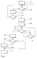
- FIG. 3 shows part of a flow diagram of a further preferred Variant of the method according to the invention, which is also with the Franking machine 2 from Figure 1 can be realized.
- the processing unit 11 initiates in a first Step 41 continuously monitor the usage status of the telephone line 4 by the monitoring device 14.
- a second step 42 the processing unit 11 checks whether a Suppression signal UDS of the monitoring device 14 at its input 11.1 is present. If this is the case, then item 41.1 becomes the second step 22 returned.
- a third step 43 in the processing unit 11 of the franking machine 2 checks whether a request to establish a connection to the data center 7. This requirement can in turn depending on specific criteria from the franking machine 2 be generated itself or entered by a user of the franking machine 2 have been.
- Step 44 establish the connection to the data center 7 by using the modem 12 controls accordingly. Then it starts at point 26.1 proceed as described in FIG. 2.
- the invention has been described above so that a fixed assignment the franking machine and the telephone 8 to a channel of the telephone line 4 exists. It goes without saying that the other telecommunications facilities 9 and 10 can be assigned to this channel or if necessary - with a normal telephone connection - only one Channel is present. The activities of other telecommunications facilities 9 and 10 can then in the same way as those of the Telephone 8 are recorded and taken into account.
- the invention has been further described as being fixed Assignment of the franking machine 2 and the further telecommunication devices 8 to 10 to the individual channels of the telephone line.
- the monitoring device can then also be designed to monitor all existing channels and only then suppresses the connection when none of the channels is free. Likewise, it can be designed so that it is only the existing connection suppressed to the data center if there is no free channel.
Applications Claiming Priority (2)
| Application Number | Priority Date | Filing Date | Title |
|---|---|---|---|
| DE10114533 | 2001-03-21 | ||
| DE10114533A DE10114533A1 (de) | 2001-03-21 | 2001-03-21 | Frankiermaschine mit einer Datenübertragungseinrichtung |
Publications (1)
| Publication Number | Publication Date |
|---|---|
| EP1244064A1 true EP1244064A1 (fr) | 2002-09-25 |
Family
ID=7678888
Family Applications (1)
| Application Number | Title | Priority Date | Filing Date |
|---|---|---|---|
| EP02090091A Withdrawn EP1244064A1 (fr) | 2001-03-21 | 2002-03-01 | Machine à affranchir avec un dispositif de transmission de données |
Country Status (3)
| Country | Link |
|---|---|
| US (1) | US20020138451A1 (fr) |
| EP (1) | EP1244064A1 (fr) |
| DE (1) | DE10114533A1 (fr) |
Cited By (1)
| Publication number | Priority date | Publication date | Assignee | Title |
|---|---|---|---|---|
| EP1577840A2 (fr) * | 2004-03-19 | 2005-09-21 | Francotyp-Postalia AG & Co. KG | Procédé de gestion à l'aide d'un serveur pour le contrôle de la sécurité des services et dispositif pour fournir des données en fonction de la gestion de la sécurité dans un système d'affranchissement |
Families Citing this family (1)
| Publication number | Priority date | Publication date | Assignee | Title |
|---|---|---|---|---|
| DE102005005484A1 (de) * | 2005-02-04 | 2006-08-10 | Deutsche Thomson-Brandt Gmbh | Netzwerkstation sowie Computer-Programm-Produkt, welches in den internen Speicher einer Netzwerkstation ladbar ist |
Citations (11)
| Publication number | Priority date | Publication date | Assignee | Title |
|---|---|---|---|---|
| US3899639A (en) * | 1973-05-11 | 1975-08-12 | Edmonton City | System and method for reading remotely located meters |
| US4059727A (en) * | 1976-01-09 | 1977-11-22 | The Post Office | Data transmission system between telephone subscriber location and telephone exchange location during idle telephone condition |
| US4540849A (en) * | 1983-06-08 | 1985-09-10 | International Teldata Ii Corp. | Meter interface unit for utility meter reading system |
| US4752950A (en) * | 1985-07-02 | 1988-06-21 | Smh Alcatel | Remote control system for franking machines |
| US4833618A (en) * | 1986-02-20 | 1989-05-23 | Net Laboratories, Inc. | System for automatically reading utility meters from a remote location |
| EP0516403A2 (fr) * | 1991-05-29 | 1992-12-02 | Neopost Limited | Procédé de télédiagnostique pour machine à affranchir |
| EP0642289A2 (fr) * | 1993-08-06 | 1995-03-08 | Sony Corporation | Gestion de données pour terminaux RNIS |
| WO1997037483A1 (fr) * | 1996-04-01 | 1997-10-09 | At & T Corp. | Mise en garde d'internet |
| WO1998051052A1 (fr) * | 1997-05-06 | 1998-11-12 | Intermec Technologies Corporation | Communication fiable sur couche transport peu fiable dans un dispositif portatif utilisant des temporisateurs configurables par l'utilisateur |
| US6073177A (en) * | 1997-08-05 | 2000-06-06 | Sterling Software, Inc. | Dynamic method for connecting a client to a server application |
| EP1056308A1 (fr) * | 1999-05-11 | 2000-11-29 | Lucent Technologies Inc. | Système et procédé pour l'utilisation d'un réseau de données comme moyen de transmission dans une boucle locale d'abonnés |
Family Cites Families (14)
| Publication number | Priority date | Publication date | Assignee | Title |
|---|---|---|---|---|
| US4311882A (en) * | 1980-01-07 | 1982-01-19 | International Standard Electric Corporation | Method of and arrangement for testing traffic routes in telecommunication networks |
| US5291545A (en) * | 1990-10-02 | 1994-03-01 | Intertex Data Ab | Apparatus and method for determining the state of a telephone line |
| US5477216A (en) * | 1992-10-30 | 1995-12-19 | General Electric Company | Electrical metering device and associated method for temporarily storing data during transmission of the data to a remote communications device |
| US5878136A (en) * | 1993-10-08 | 1999-03-02 | Pitney Bowes Inc. | Encryption key control system for mail processing system having data center verification |
| EP0723355A1 (fr) * | 1995-01-18 | 1996-07-24 | T.R.T. Telecommunications Radioelectriques Et Telephoniques | Système de transmission à compression de données |
| US5764158A (en) * | 1995-11-20 | 1998-06-09 | Water Savers, Inc. | Meter reading data transmissiion system and method of using same |
| US6157919A (en) * | 1995-12-19 | 2000-12-05 | Pitney Bowes Inc. | PC-based open metering system and method |
| US6151590A (en) * | 1995-12-19 | 2000-11-21 | Pitney Bowes Inc. | Network open metering system |
| EP0788270A3 (fr) * | 1996-01-31 | 2003-11-19 | Deutsche Telekom AG | Procédé et dispositif de transfert rapide d'un message d'alarme ou de secours par modem |
| FR2745966B1 (fr) * | 1996-03-08 | 1998-06-05 | Jean Luc Leleu | Passerelle de peage pour reseau de transmission de donnees |
| US7028088B1 (en) * | 1996-04-03 | 2006-04-11 | Scientific-Atlanta, Inc. | System and method for providing statistics for flexible billing in a cable environment |
| US5910179A (en) * | 1996-10-25 | 1999-06-08 | Pitney Bowes Inc. | Method and system for transmitting data within a tree structure and receiving a confirmation or status therefor |
| DE19818708A1 (de) * | 1998-04-21 | 1999-11-04 | Francotyp Postalia Gmbh | Verfahren zum Nachladen eines Portoguthabens in eine elektronische Frankiereinrichtung |
| US6721282B2 (en) * | 2001-01-12 | 2004-04-13 | Telecompression Technologies, Inc. | Telecommunication data compression apparatus and method |
-
2001
- 2001-03-21 DE DE10114533A patent/DE10114533A1/de not_active Withdrawn
-
2002
- 2002-02-13 US US10/074,838 patent/US20020138451A1/en not_active Abandoned
- 2002-03-01 EP EP02090091A patent/EP1244064A1/fr not_active Withdrawn
Patent Citations (11)
| Publication number | Priority date | Publication date | Assignee | Title |
|---|---|---|---|---|
| US3899639A (en) * | 1973-05-11 | 1975-08-12 | Edmonton City | System and method for reading remotely located meters |
| US4059727A (en) * | 1976-01-09 | 1977-11-22 | The Post Office | Data transmission system between telephone subscriber location and telephone exchange location during idle telephone condition |
| US4540849A (en) * | 1983-06-08 | 1985-09-10 | International Teldata Ii Corp. | Meter interface unit for utility meter reading system |
| US4752950A (en) * | 1985-07-02 | 1988-06-21 | Smh Alcatel | Remote control system for franking machines |
| US4833618A (en) * | 1986-02-20 | 1989-05-23 | Net Laboratories, Inc. | System for automatically reading utility meters from a remote location |
| EP0516403A2 (fr) * | 1991-05-29 | 1992-12-02 | Neopost Limited | Procédé de télédiagnostique pour machine à affranchir |
| EP0642289A2 (fr) * | 1993-08-06 | 1995-03-08 | Sony Corporation | Gestion de données pour terminaux RNIS |
| WO1997037483A1 (fr) * | 1996-04-01 | 1997-10-09 | At & T Corp. | Mise en garde d'internet |
| WO1998051052A1 (fr) * | 1997-05-06 | 1998-11-12 | Intermec Technologies Corporation | Communication fiable sur couche transport peu fiable dans un dispositif portatif utilisant des temporisateurs configurables par l'utilisateur |
| US6073177A (en) * | 1997-08-05 | 2000-06-06 | Sterling Software, Inc. | Dynamic method for connecting a client to a server application |
| EP1056308A1 (fr) * | 1999-05-11 | 2000-11-29 | Lucent Technologies Inc. | Système et procédé pour l'utilisation d'un réseau de données comme moyen de transmission dans une boucle locale d'abonnés |
Cited By (2)
| Publication number | Priority date | Publication date | Assignee | Title |
|---|---|---|---|---|
| EP1577840A2 (fr) * | 2004-03-19 | 2005-09-21 | Francotyp-Postalia AG & Co. KG | Procédé de gestion à l'aide d'un serveur pour le contrôle de la sécurité des services et dispositif pour fournir des données en fonction de la gestion de la sécurité dans un système d'affranchissement |
| EP1577840A3 (fr) * | 2004-03-19 | 2007-07-25 | Francotyp-Postalia GmbH | Procédé de gestion à l'aide d'un serveur pour le contrôle de la sécurité des services et dispositif pour fournir des données en fonction de la gestion de la sécurité dans un système d'affranchissement |
Also Published As
| Publication number | Publication date |
|---|---|
| US20020138451A1 (en) | 2002-09-26 |
| DE10114533A1 (de) | 2002-10-02 |
Similar Documents
| Publication | Publication Date | Title |
|---|---|---|
| DE3943355C2 (de) | System und Verfahren zur Entsendung und Zuteilung von Hilfsmitteln | |
| DE69326582T2 (de) | Verbindungssicherung in einem digitalen Fernmeldesystem | |
| EP0470283B1 (fr) | Méthode et dispositif pour déterminer la qualité de circuits virtuels transitant par un dispositif de commutation ATM | |
| DE19508081A1 (de) | Verfahren zum Steuern eines Zugangsnetzes sowie Vermittlungsstelle und Zugangsnetz damit | |
| DE2930586C2 (fr) | ||
| EP1244064A1 (fr) | Machine à affranchir avec un dispositif de transmission de données | |
| EP0700223A2 (fr) | Système de communication | |
| DE19542724A1 (de) | ISDN-Endgerät mit einer Datenschnittstelle | |
| DE69933646T2 (de) | Rechnungsverfahren in einer elektronischen vermittlung in einem zellularen netz | |
| EP0332977B1 (fr) | Méthode pour la réalisation des liaisons de transfert de données dans un central de télécommunication | |
| EP0475180A1 (fr) | Procédé de transmission de paquets de communication entre des lignes de raccordement existantes dans un commutateur | |
| DE3220511C2 (de) | Schaltungsanordnung fuer eine fernsprechvermittlungsanlage mit verbindungsindividuellen leitungsuebertragungen. | |
| EP0187945A2 (fr) | Méthode pour la transmission de signaux entre un central de traitement de données et un central téléphonique, en particulier un central téléphonique privé | |
| DE10146555B4 (de) | Verfahren zur Löschung von Überwachungsdaten und Überwachungsvorrichtung | |
| DE3136524C2 (fr) | ||
| DE2941907C2 (de) | Schaltungsanordnung zur Anschaltung von Bedienplätzen und Ansageeinrichtungen einer Fernsprech-Auskunfts- und/oder Auftrags-Stelle an einen rufenden, identifizierbaren Teilnehmeranschluß | |
| DE3329571A1 (de) | Verfahren zum betreiben von bildschirmtextanschluessen | |
| EP0032677B1 (fr) | Procédé pour la surveillance de dispositifs occupés dans un central de télécommunication, en particulier dans un central téléphonique | |
| DE3315268C2 (de) | Verfahren zur Bestimmung der Zeitdauer von zu sendenden oder zu empfangenden Signalen auf Verbindungsleitern in Fernmelde-, insbesondere Fernsprechvermittlungsanlagen | |
| DE2945613C2 (de) | Verfahren und Schaltungsanordnung zur teilnehmerindividuellen Aufnahme von (Wahl-) Informationen in direkt gesteuerten Fernsprechvermittlungsanlagen | |
| DE2839172B2 (de) | Verfahren zur Fernverwaltung von Datenspeichern und zur Fernwartung in einem zentralgesteuerten Fernsprechvermittlungssystem, insbesondere in zentralgesteuerten Fernsprechnebenstellenanlagen mit Verbindungsverkehr | |
| DE2155173C3 (de) | Notüberwachungseinrichtung für eine elektronische Vermittlungseinrichtung | |
| DE3205172C1 (de) | Verfahren zum Ermitteln der Verkehrsbelastung von zentralen Steuereinrichtungen in Fernmelde-, insbesondere Fernsprechanlagen | |
| DE4243635C2 (de) | Überwachung von Fernsprech-Datenverbindungen | |
| DE3400588A1 (de) | Verfahren und schaltungsanordnung zum uebertragen von datensignalen |
Legal Events
| Date | Code | Title | Description |
|---|---|---|---|
| PUAI | Public reference made under article 153(3) epc to a published international application that has entered the european phase |
Free format text: ORIGINAL CODE: 0009012 |
|
| AK | Designated contracting states |
Kind code of ref document: A1 Designated state(s): AT BE CH CY DE DK ES FI FR GB GR IE IT LI LU MC NL PT SE TR |
|
| AX | Request for extension of the european patent |
Free format text: AL;LT;LV;MK;RO;SI |
|
| 17P | Request for examination filed |
Effective date: 20021213 |
|
| 17Q | First examination report despatched |
Effective date: 20030422 |
|
| AKX | Designation fees paid |
Designated state(s): CH DE FR GB IT LI |
|
| RAP1 | Party data changed (applicant data changed or rights of an application transferred) |
Owner name: FRANCOTYP-POSTALIA GMBH |
|
| GRAP | Despatch of communication of intention to grant a patent |
Free format text: ORIGINAL CODE: EPIDOSNIGR1 |
|
| STAA | Information on the status of an ep patent application or granted ep patent |
Free format text: STATUS: THE APPLICATION IS DEEMED TO BE WITHDRAWN |
|
| 18D | Application deemed to be withdrawn |
Effective date: 20130618 |