EP1243447A2 - Closed height control device for vehicles - Google Patents
Closed height control device for vehicles Download PDFInfo
- Publication number
- EP1243447A2 EP1243447A2 EP02004708A EP02004708A EP1243447A2 EP 1243447 A2 EP1243447 A2 EP 1243447A2 EP 02004708 A EP02004708 A EP 02004708A EP 02004708 A EP02004708 A EP 02004708A EP 1243447 A2 EP1243447 A2 EP 1243447A2
- Authority
- EP
- European Patent Office
- Prior art keywords
- compressed air
- pressure medium
- air line
- line
- valve
- Prior art date
- Legal status (The legal status is an assumption and is not a legal conclusion. Google has not performed a legal analysis and makes no representation as to the accuracy of the status listed.)
- Granted
Links
Images


Classifications
-
- B—PERFORMING OPERATIONS; TRANSPORTING
- B60—VEHICLES IN GENERAL
- B60G—VEHICLE SUSPENSION ARRANGEMENTS
- B60G17/00—Resilient suspensions having means for adjusting the spring or vibration-damper characteristics, for regulating the distance between a supporting surface and a sprung part of vehicle or for locking suspension during use to meet varying vehicular or surface conditions, e.g. due to speed or load
- B60G17/02—Spring characteristics, e.g. mechanical springs and mechanical adjusting means
- B60G17/04—Spring characteristics, e.g. mechanical springs and mechanical adjusting means fluid spring characteristics
- B60G17/052—Pneumatic spring characteristics
- B60G17/0523—Regulating distributors or valves for pneumatic springs
-
- B—PERFORMING OPERATIONS; TRANSPORTING
- B60—VEHICLES IN GENERAL
- B60G—VEHICLE SUSPENSION ARRANGEMENTS
- B60G2400/00—Indexing codes relating to detected, measured or calculated conditions or factors
- B60G2400/50—Pressure
- B60G2400/51—Pressure in suspension unit
- B60G2400/512—Pressure in suspension unit in spring
- B60G2400/5122—Fluid spring
- B60G2400/51222—Pneumatic
-
- B—PERFORMING OPERATIONS; TRANSPORTING
- B60—VEHICLES IN GENERAL
- B60G—VEHICLE SUSPENSION ARRANGEMENTS
- B60G2400/00—Indexing codes relating to detected, measured or calculated conditions or factors
- B60G2400/50—Pressure
- B60G2400/52—Pressure in tyre
-
- B—PERFORMING OPERATIONS; TRANSPORTING
- B60—VEHICLES IN GENERAL
- B60G—VEHICLE SUSPENSION ARRANGEMENTS
- B60G2500/00—Indexing codes relating to the regulated action or device
- B60G2500/20—Spring action or springs
- B60G2500/201—Air spring system type
- B60G2500/2014—Closed systems
-
- B—PERFORMING OPERATIONS; TRANSPORTING
- B60—VEHICLES IN GENERAL
- B60G—VEHICLE SUSPENSION ARRANGEMENTS
- B60G2500/00—Indexing codes relating to the regulated action or device
- B60G2500/20—Spring action or springs
- B60G2500/202—Height or leveling valve for air-springs
-
- B—PERFORMING OPERATIONS; TRANSPORTING
- B60—VEHICLES IN GENERAL
- B60G—VEHICLE SUSPENSION ARRANGEMENTS
- B60G2500/00—Indexing codes relating to the regulated action or device
- B60G2500/30—Height or ground clearance
-
- B—PERFORMING OPERATIONS; TRANSPORTING
- B60—VEHICLES IN GENERAL
- B60G—VEHICLE SUSPENSION ARRANGEMENTS
- B60G2800/00—Indexing codes relating to the type of movement or to the condition of the vehicle and to the end result to be achieved by the control action
- B60G2800/90—System Controller type
- B60G2800/91—Suspension Control
- B60G2800/912—Attitude Control; levelling control
Definitions
- the invention relates to a closed level control system for vehicles according to the Preamble of claim 1.
- Such a level control system is known from DE 199 59 556 C1.
- the one from this Known level control system has an air dryer, over the air with With the help of the compressor sucked out of the atmosphere and for leakage compensation in the Pressure fluid reservoir can be transferred.
- For regeneration of the air dryer can compressed air from the pressure medium reservoir via the air dryer into the Atmosphere.
- dehumidified in the level control system Air is located so that the components of the level control system from corrosion and Icing are protected.
- level control system of the air dryer directly faces the atmosphere, so that it constantly absorbs humidity from it. This can possibly do so cause the air dryer not to perform its function or to perform it insufficiently. This The problem could be solved by dimensioning the air dryer accordingly becomes, however, a complicated structure and high cost of the air dryer would lead.
- the invention is based on the object of a closed level control system create that has an air dryer that is always available for air drying stands and which can also have a simple structure.
- An advantage of the invention is that the air dryer is in a compressed air line the level control system and at least through the intake valve or is completely shielded from the atmosphere by the drain valve. Thus the Preventing the risk that the air dryer constantly releases atmospheric moisture receives.
- Another advantage of the invention is that the air dryer is on the compressor outlet side (i.e. on the pressure side of the compressor) is arranged, which leads to a particularly high effectiveness of the air dryer during the Drying operation leads. For this reason, the air dryer can be a simple one Structure and a small sized dryer bed.
- Another advantage of Invention can be seen in the fact that, although the air dryer is completely closed Level control system is integrated, compressed air from the compressed air reservoir via the Air dryer (for its regeneration) can be released into the atmosphere.
- the air dryer is flowed through in the opposite direction during the regeneration operation than during the drying operation. This is a good regeneration of the dryer guaranteed (for details see figure description).
- Claim 2 relates to a first embodiment of the invention, which in context is explained in more detail with FIG.
- the advantage of the embodiment is there too see that only 2/2-way valves are arranged in the four compressed air lines, which have a simple structure and are inexpensive.
- Claim 3 relates to a further embodiment of the invention, which in Connection with Figure 2 is explained in more detail.
- the advantage of the embodiment can be seen in the fact that only two 3/2-way valves are arranged in the four compressed air lines are that have a simple structure and are inexpensive.
- the first compressed air line which extends from the compressed air tank, and the third end Compressed air line, which starts from the pressure medium chambers, in a common point, which is directly connected to the compressor input.
- the advantage of this training is the fact that in a certain position the overflow of compressed air from the pressure medium chambers in both 3/2-way valves the pressure medium reservoir is impossible, regardless of whether the Air pressure in the pressure medium chambers is greater or less than the air pressure in the Pressure fluid reservoir.
- the controllable directional valves can for example be in this position be transferred so that an unintentional overflow of compressed air between the Pressure medium chambers and the pressure medium reservoir can not take place.
- such a defined state of the controllable directional valves Pressure measurement of the pressure in the pressure medium chambers with the help of a pressure sensor simple way possible (for details see explanations on Fig. 2).
- the level control system has a further controllable directional valve, which the Connection between the air springs and the compressor and air dryer blocks, however allows a connection between the air springs and the pressure sensor.
- a further controllable directional valve which the Connection between the air springs and the compressor and air dryer blocks, however allows a connection between the air springs and the pressure sensor.
- the advantage of the development of the invention is that with a pressure measurement in one Air spring regardless of the switching state of the two 3/2-way valves, no air in the Air dryer or compressor can escape and therefore no pressure change in the respective air spring takes place because the additional controllable directional valve this Connection blocks, and thus no misalignment of the vehicle is generated and none Readjustment of the vehicle level after a pressure measurement in an air spring necessary is.
- the Drain line connected to the suction line, between the point at which the Drain line branches off from the fourth compressed air line and the point at which it connects with the Suction line is connected, a directional control valve is arranged, which is in a first switching state blocks the drain line and switches the drain line through in a second switching state, so that the suction valve can also be used as a drain valve.
- the intake valve is in one Compressed air line that branches off from the second common compressed air line.
- the drain line is correct between the point where it branches off from the fourth air line and the Point where it is connected to the suction line with the second compressed air line match.
- Claim 10 relates to a further embodiment of the invention, which in Connection with Figure 3 is explained in more detail.
- the fourth Compressed air line between the air dryer and the pressure medium reservoir Air dryer opening check valve arranged by a compressed air line, in which a choke is arranged, is bridged.
- the level control system a pressure sensor in a compressed air line extending from the pressure medium chambers is arranged, between each pressure medium chamber and the pressure sensor a controllable directional valve is located, the pressure medium chambers in a first switching state separates from the pressure sensor and in a second switching state Pressure medium chamber connects to the pressure sensor.
- the level control system is included equipped with several compressors, with each compressor going forward on its own described way with the pressure medium reservoir and with certain pressure medium chambers connected is. So there is no longer a single compressor for the whole System with all pressure medium chambers responsible, but has a single compressor only a part of the pressure medium chambers, in extreme cases only one Pressure medium chamber to supply. Multiple compressors can simultaneously Supply air to the pressure medium chambers or extract air from the pressure medium chambers. at Such operations can be carried out much more quickly than in parallel operation conventional level control systems, in which all the air over a single Compressor is guided.
- the development of the invention according to claim 9 thus has the Advantage that you can bring about changes in the level of the vehicle faster than with a conventional level control system.
- Claim 9 also has the advantage that part of the pressure medium chambers air supplied and at the same time air is withdrawn from other pressure medium chambers can and air between individual pressure medium chambers or groups of pressure medium chambers can be exchanged.
- a system according to claims 1 to 8 which allows individual control of the individual air springs, but only either in the "refill” or "empty” mode, but not in both Operating modes simultaneously, this results in the advantage of expanded control options.
- this system there are good opportunities, more Programs for the control and regulation of the chassis, which are regulated by the Levels can go beyond to implement.
- the pressure medium chambers of each axis, according to the embodiment of claim 15 even the pressure medium chambers each Wheel of the vehicle assigned its own compressor.
- the embodiment according to Claim 10 has the advantage that rapid changes in pressure with little Effort can be achieved. In a vehicle with two axles, it can double the speed of level changes compared to conventional systems with only can be achieved with a compressor.
- the embodiment according to claim 11 has the The advantage that even faster reactions are possible, and that with every bike individual regulations completely independent of the other pressure medium chambers can be made.
- the pressure medium chambers The individual vehicle axles each have their own buffer for the Assigned pressure medium. When lowering the vehicle, these buffers can be used absorb large amounts of air from the pressure medium chambers in a short time, creating a rapid lowering of the vehicle is made possible. From the buffers, the Air is then fed into the pressure medium reservoir via the compressor, this air can be transported slowly without lowering of the vehicle would be slowed down.
- the emptying of the pressure medium chambers for lowering the level Vehicle from the flow of the pressure medium in the other parts of the system to which the compressor, which includes valves and relatively long piping systems, in time decoupled. It is possible to quickly empty the pressure medium chambers without the entire system to be designed for rapid displacement of large air masses needs. In comparison to the alternative embodiments according to claims 12 to 15 this embodiment has the advantage that only a single compressor is required is.
- the output lines of the intermediate store are preferably with check valves provided an unimpeded outflow of the pressure medium from the buffer allow, but prevent the inflow of air from the system. In this way the result is that the pressure in the intermediate stores is always lower than in the Pressure medium chambers.
- the individual pressure medium chambers each assigned a directional valve, which with the to the entrance of the Compressor leading fluid lines is connected. Through these valves one Control to compensate for pitch and roll movements of the vehicle, as explained in more detail below.
- the line for connecting external devices is equipped with a closure that only then opens when an external device is connected to the line.
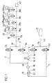
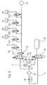
- Figure 1 shows a level control system in a schematic representation, the Pressure medium chambers in the form of air springs 6a - 6b, a compressor 8, one Air dryer 10 and a compressed air reservoir 12 contains.
- the compressed air tank 12 stands with a first compressed air line 1, which is guided via a first directional valve 1a the compressor inlet 14 and a fourth compressed air line 4, in which a controllable 2/2-way valve 4a and the air dryer 10 lies with the compressor outlet 16 in Connection. Between the air dryer 10 and the compressed air reservoir 12 is in the fourth compressed air line 4 opens towards the compressed air reservoir 12
- Check valve 18 is arranged by a compressed air line 20 in which a throttle 22nd is bridged.
- the first compressed air line 1 and the fourth compressed air line 4 are in a point 24, which is between the controllable 2/2-way valves 1a and 4a and the compressed air reservoir 12 is merged. Based on this point 24 they are in a common compressed air line 46 to the compressed air reservoir 12 touched.
- the compressor output 16 is via a second compressed air line 2, which is controllable Directional control valve 2a and one controllable each associated with an air spring 6a - 6d Directional valve 26a - 26d is guided, can be connected to each air spring 6a - 6d. Furthermore is the compressor input 14 via a third compressed air line 3, which is controllable Directional valve 3a and the controllable directional valves 26a - 26d is guided, also with each Air spring 6a - 6d connectable.
- the second compressed air line 2 and the third compressed air line 3 are in a point 28, which is between the directional control valves 2a and 3a and the air springs 6a - 6d lies, connected to each other.
- the 2/2-way valves 1a - 4a can be in a first valve block and the directional valves 26a - 26d and the suction valve 30 (the function of which will be explained later) can be combined in one second valve block can be summarized.
- an air spring 6a - 6d in the level control system Compressor 8 can be filled from the compressed air reservoir 12 (using the example the air spring 6a).
- the control unit (not shown)
- Directional control valves 1a, 2a and 26a are controlled so that they differ from that shown in FIG change the first switching state into the second switching state.
- the compressed air line 1 is then switched through so that the compressed air tank 12 with the compressor inlet 14 connected is.
- the compressed air line 2 is switched through, so that the Compressor outlet 16 is connected to the air spring 6a.
- compressed air from the Compressed air reservoir 12 via the directional control valve 1a, the compressor 8, via the Directional control valve 2a and the directional control valve 26a can be transferred to the air spring 6a.
- the Control unit also controls the compressor 8 so that it starts to run and the Air spring 6a is filled. If the filling process is to be canceled, the Directional control valves 1a, 2a and 26a are no longer energized by the control unit, so that these go back to the first switching state. In addition, the compressor 8 no longer controlled so that it no longer runs.
- Air spring 6a The following explains how the air springs 6a - 6d via the compressor 8 Compressed air can be transferred into the compressed air reservoir 12 (using the example of Air spring 6a).
- the control unit of the level control system Directional control valves 26a, 3a and 4a are controlled so that they are different from those shown in FIG change the first switching state into the second switching state.
- Air spring 6a connected to the compressor inlet 14 via the compressed air line 3.
- the compressor output 16 via the compressed air line 4 with the Compressed air reservoir 12 connected.
- the air spring 6a can then via the directional valve 26a, the directional valve 3a, the compressor 8, the air dryer 10, the check valve 18 and the directional control valve 4a are emptied into the compressed air reservoir 12.
- the compressor 8 is emptied by the control unit of the level control system controlled so that it starts to run and supports the emptying process.
- the directional control valves 26a, 3a and 4a from the Control unit is no longer energized, so that it returns to the first switching state pass.
- the compressor 8 is no longer activated, so that it stop running.
- the compressor 8 delivers both during filling and during emptying an air spring 6a - 6d only compressed air from the compressor inlet 14 to Compressor output 16, so that only one compressor is required, which only in one Can convey towards compressed air. The same applies to what is described below Embodiment.
- the level control system has a Intake valve 30, which is located in a compressed air line through which the compressor inlet 14 is connectable to the atmosphere.
- Intake valve 30 is preferably in one Compressed air line 32 that branches off from the compressed air line 34 at a point 36 that lies between point 28 and the branches 38a-38d to the air springs 6a-6d.
- Compressed air can be drawn from the atmosphere via the suction valve 30 as follows Compressor 8 are transferred to the compressed air reservoir 12: First of all the control unit of the level control system, the intake valve 30, the controllable directional valve 3a and the controllable directional valve 4a, so that this is different from that in FIG shown basic state change into their switching state.
- Control unit of the compressor 8 controlled so that it starts to run. outgoing of the compressed air line 32 is then controlled via the intake valve 30 Directional control valve 3a, the compressor 8, the air dryer 10, the check valve 18 and over the controllable directional valve 4a compressed air from the atmosphere in the Compressed air reservoir 12 transferred. The compressed air is thereby in the air dryer 10 dried, moving in a first direction (from right to left in the figure) is flowed through.
- the level control system also has a compressed air line from the fourth Compressed air line 4 branches off at a point 40 which is between the compressor outlet 16 and the air dryer 10 and via which the compressed air reservoir 12 via the Air dryer 10 and can be connected to the atmosphere via a drain valve.
- Intake valve 30 As a drain valve in the embodiment shown Intake valve 30. used.
- a discharge of compressed air from the compressed air reservoir 12 is carried out as follows: First, the control unit of the level control system does the controllable directional valve 4a, the controllable directional valve 2a and the intake valve 30 controlled, so that this of the basic state shown in Figure 1 in their Switch switching status.
- the compressed air reservoir 12 is then controllable Directional control valve 4a, the throttle 22, the air dryer 10, the controllable directional control valve 2a and the Intake valve 30 connected to the atmosphere so that it can be emptied into it.
- the air dryer 10 turns in the opposite direction (i.e. from left to right in the figure) as during filling from the atmosphere flows through, so that it can regenerate particularly effectively.
- the air springs 6a - 6d must be controlled Directional valves are separated from the atmosphere so that they do not accidentally be emptied. In the embodiment shown, this is done by the controllable Directional control valves 26a - 26d. To end the draining process, the directional control valves 4a, 2a and 30 are no longer energized by the control unit, so that they are back in their Override basic state.
- the level control system in the compressed air line 34 has one Pressure sensor 42, with which the pressure in the air springs 6a-6d is measured as follows can (explained on the air spring 6a): First, the control unit The level control system controls the directional control valve 26a, so that this is different from that shown in FIG shown basic state changes into its switching state. The air spring 6a is then with connected to the pressure sensor 42, so that the corresponding pressure is measured there and on the control unit of the level control system can be passed on. With the help of Pressure sensor 42 can also measure the pressure in the compressed air reservoir 12. are activated by the control unit controlling the controllable directional valves 1a and 3a, so that it switches from the basic state shown in FIG. 1 to its switching state pass. The compressed air reservoir 12 is then via the controllable directional valves 1a and 3a and connected to it via the compressed air line 34 so that the corresponding one Pressure can be measured and passed on to the control unit.
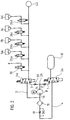
- FIG. 2 shows a level control system that largely corresponds to that shown in FIG. 1 Level control system corresponds.
- controllable directional valves 1a and 4a in the controllable 3/2-way valve 2a and the controllable directional valves 2a and 3a shown in FIG. 1 into the controllable 3/2-way valve 4a summarized.
- the compressed air line 1 is based on the Compressed air tank 12 led to a point 29 via the controllable directional valve 2a.
- the Compressed air line 3 is based on the controllable from the air springs 6a to 6d
- Directional control valve 4a also leads to point 29, so that the compressed air line 1 and the Compressed air line 3 are connected to one another at this common point 29.
- the Common point 29 of compressed air lines 1 and 3 is (if necessary via a short compressed air line as also shown in FIG. 2) directly connected to the compressor inlet 14.
- first compressed air line 1 is between the common point 29 and the controllable directional valve 2a to the common point 29 and to the compressor inlet 14 non-return valve 31 arranged.
- compressed air line 3 is between the common point 29 and the controllable directional valve 4a also to common point 29 and check valve opening towards the compressor inlet 14 33 arranged.
- the functions of the level control system according to FIG. 2 are explained below.
- the air spring 6a is then via the compressed air line 3, in which the switched directional control valves 26a and 4a and the check valve 33, with the Compressor input 14 connected.
- the compressor output 16 is via the Compressed air line 4, in which the air dryer 10, the check valve 18 and that switched directional control valve 2a, connected.
- the air can therefore start from the Air spring 6a can be transferred into the compressed air tank 12 with the aid of the compressor 8 (For details see Fig. 1).
- the compressed air line 2 is through the controllable directional valve 4a and the compressed air line 1 through the controllable directional valve 2a blocked.
- the controllable directional valve 26a transferred back to the switching state shown in FIG. 2.
- the air springs 6b to 6d is followed accordingly, with the difference that the controllable Directional control valves 26b to 26d assume the corresponding switch positions.
- the controllable directional valves 4a and 26a of the one shown in FIG Switching state transferred to the other switching state.
- the compressed air tank 12 is then via the compressed air line 1, in which the switched controllable directional valve 2a and Check valve 31 are connected to the compressor inlet 14.
- the Compressor outlet 16 is via the compressed air line 2, in which the switched through controllable directional valve 4a and the controllable directional valve 26a lie with the air spring 6a connected. So there can be compressed air from the compressed air tank 12 via the compressor 8 be transferred into the air spring 6a.
- the compressed air line is 3 through the controllable directional valve 4a and the compressed air line 4 through the controllable Directional valve 2a blocked.
- At the end of the process at least the controllable Directional control valve 26a is brought back into the switching state shown in FIG. 2.
- the Air springs 6b to 6d are in a corresponding manner with compressed air from the Compressed air tank 12 filled.
- controllable directional control valves 30 and 2a from the switching state shown in FIG transferred the other switching state.
- the atmosphere is then via the controllable directional valve 30, the controllable directional valve 4a and the check valve 33 with the Compressor input 14 connected.
- the compressor output 16 is via the Compressed air line 4, in which the air dryer 10, the check valve 18 and the switched through controllable directional valve 2a is connected to the compressed air tank 12, so that filling the compressed air tank 12 with the help of the compressor 8 with air from the Atmosphere is possible.
- the compressed air line 2 is through the controllable directional valve 4a and the compressed air line 1 through the controllable directional valve 2a blocked.
- At least the controllable directional valve 30 is used to end the process transferred back to the switching state shown in FIG. 2.
- controllable directional valve 2a, 4a and 30 from that shown in FIG Switching state transferred to the other switching state.
- the compressed air tank 12 is then via the controllable directional valve 2a, the throttle 22, the air dryer 10, the controllable Directional control valve 4a and the controllable directional control valve 30 are connected to the atmosphere, so that Compressed air from the compressed air reservoir 12 can flow into this.
- the Compressed air passed over the air dryer 10 so that it can be regenerated.
- the above explanations show that the functions of the Level control system (transfer of compressed air from the air springs 6a to 6d into the compressed air tank 12; Transfer of compressed air from the compressed air tank 12 into the air springs 6a to 6d; Filling the compressed air tank 12 with air from the atmosphere; Draining of Compressed air from the compressed air tank 12 into the atmosphere via the air dryer 10) are not affected by the check valves 31 and 33.
- Air springs 6a to 6d can be measured.
- a Air exchange between the air springs 6a to 6d and the compressed air tank 12 if possible be avoided to inadvertently lower or raise the vehicle body to avoid. It is therefore to be avoided that compressed air is released during the pressure measurement the air springs 6a to 6d flow into the compressed air tank (this could happen if the air pressure in the air spring 6a to 6d to be measured is greater than the air pressure in the Compressed air tank 12).
- the pressure measurement in one of the air springs 6a to 6d becomes an example explained using the air spring 6a.
- the controllable becomes for measuring the air pressure Directional control valve 26a from the switching state shown in FIG. 2 to the other switching state transferred so that the air spring 6a via the controllable directional valve 26a with the Pressure sensor 42 is connected and by means of which the air pressure can be measured. If the air pressure in the air spring 6a is greater than the air pressure in the compressed air tank 12, so no compressed air from the air spring 6a in the Overflow compressed air tank 12. The air from the air spring 6a namely reaches the controllable directional valves 26a and 4a and the check valve 33 to the Check valve 31, which blocks towards the controllable directional valve 2a.
- the air pressure in the compressed air tank 12 is greater than the air pressure in the air spring 6a, it is also not possible that compressed air from this into the Air spring 6a overflows.
- the air can start from the Compressed air tank 12 via the controllable directional valve 2a and the check valve 31 only to get to the check valve 33, the controllable directional valve 4a and Air spring 6a locks out.
- An overflow of compressed air from the compressed air tank 12 in the air spring 6a via another path is also not possible because the compressed air line 4 through the directional valve 2a and the compressed air line 2 through the directional valve 4a is interrupted.
- controllable directional valve 26a is again in the in transferred the state shown in Figure 1.
- the air pressure measured in the air springs 6b to 6d in which case the corresponding directional valve 26b to 26d from the switching state shown in FIG. 2 to the other switching state is transferred.
- FIG. 3 shows a level control system that largely corresponds to that shown in FIG. 1 Level control system corresponds.
- Level control system corresponds.
- the level control system shown in FIG. 2 corresponds in terms of their general structure of the level control system shown in DE 199 59 556 C1, so that with respect to filling the air springs 6a-6d from the compressed air reservoir 12 and transferring compressed air from the air springs 6a-6d to the compressed air reservoir 12 is referred to this document.
- the level control system contains an air dryer 10, which is arranged in the fourth compressed air line 4, via which the Compressor outlet 16 via the directional valve 4a with the compressed air reservoir 12 is connectable (the connection is established when the directional valve 4a of the in the switching state shown in Figure 3 changes to its other switching state).
- Level control system according to Figure 3 constructed the same way as the level control system according to Figure 1, so that reference is made to the above description of the figures.
- about Intake valve 30 may receive compressed air from the atmosphere via compressor 8 as follows be transferred into the compressed air tank 12: First, the (not shown) Control unit of the level control system, the valve 30, the directional control valve 2a and the directional control valve 4a controlled, so that this of the switching state shown in Figure 3 in their switch to another switching state. Thereupon the compressor 8 controlled so that compressed air from the atmosphere via the intake valve 30, the Directional control valve 2a, the compressor 8, the air dryer 10, the check valve 18 and the Directional control valve 4a is transferred into the compressed air reservoir 12. To end this Process, the control unit in turn controls the compressor 8, so that this stops running and, moreover, the suction valve 30 is no longer energized, so that this changes again into the state shown in FIG. 3 and for Blocks the atmosphere.
- the Level control system via a compressed air line from the fourth compressed air line 4 in a point 40 that branches between the compressor outlet 16 and the air dryer 10 lies and which can be connected to the atmosphere via a drain valve 44.
- the compressed air reservoir 12 is emptied as follows: from the control unit of the The level control system controls the directional control valves 44 and 4a so that they are controlled by the Switch to the other switching state shown in Figure 3.
- the Compressed air reservoir 12 is then on the directional control valve 4a, the compressed air line with the Throttle 22, air dryer 10 and drain valve 44 are connected to the atmosphere.
- At least the directional control valve is used by the control unit to end the draining process 44 is no longer energized, so that this is again shown in FIG Switching state changes and blocks to the atmosphere.
- the air dryer flows in the opposite direction as during the Filling the compressed air reservoir.
- FIGS. 4-8 exemplary embodiments of the invention are shown, through which additional functions of the level control system are made possible. The basis are however, always systems as described in connection with Figures 1 to 3 have been.
- FIGS. 4-8 are level control systems shown, which are constructed similarly to that in connection with FIG. 1 Described. However, these developments of the invention could also be carried out in an analogous manner be built on level control systems in the sense of FIGS. 2 and 3.
- Figures 4 to 8 are the same for components that have not been changed from FIG. 1 Maintain reference numbers.
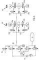
- Fig. 4 shows two control loops 100 and 200, both of the same and in the same way as are constructed in Fig. 1.
- the control loops 100 and 200 become one Pressure fluid reservoir 12 fed.
- the control loops e.g. 100
- they will pressure medium chambers belonging to the front axle of the vehicle, e.g. 6a and 6b, and through the other control circuit (in this example 200) the pressure medium chambers (in this example 6c and 6d) supplied with air and controlled.
- Both control loops 100 and 200 have compressors 108 and 208, the inputs 114 of which or 214 via directional valves 101a or 201a and compressed air lines 101 or 201 with the Pressure medium reservoir 12 and via directional valves 103a and 203a and compressed air lines 103 or 203 with the pressure medium chambers 6a and 6b or 6c and 6d of the related vehicle axles.
- the outputs 116 and 216 of the Compressors 100, 200 are via compressed air lines 102 and 202 and directional control valves 102a or 202a with the pressure medium chambers 6a, 6b or 6c, 6d and via compressed air lines 104 and 204 and directional valves 104a and 204a with the pressure medium reservoir 12 connected.
- the control loops 100 and 200 are also with pressure sensors 142 and 242 fitted.
- An air dryer 10 is arranged in the compressed air line 104 of the control circuit 100 a throttle 22 and a parallel check valve 18 are connected upstream. Over a Line 32, which is provided with a valve 30, can remove air from the environment recorded or released into the environment.
- the mode of action of this Facilities is the same as in Fig. 1.
- These facilities are only in control loop 100, but not provided in the control loop 200. This is possible because, on the one hand, the Control trip 100 and 200 in connection with each other via the pressure medium reservoir 12 stand, and there is also an exchange with a closed level control system the environment to a small extent, especially to compensate for leakage losses, takes place.
- Fig. 4 shows a level control system for a vehicle with two axes. It goes without saying that for a vehicle with more than two axles the control loops 100 and 200 still other similar control loops can be connected in parallel, so that each axis separate control loop with compressor is assigned.
- each pressure medium chamber 6a-6d has its own control circuit 100, 200, 300 and 400 is assigned, the control loops 100, 200, 300, 400 again in the preceding are constructed and each have their own compressors 108, 208, 308 and Have 408.
- the level control system shown in Fig. 6 has a control circuit of the type described in connection with Fig. 1.
- the front or pressure medium chambers belonging to the rear axle each in groups 50, 51 ' summarized. One with more than two axes would correspondingly have more of these Have groups.
- the Pressure medium accumulators 51, 51 ' are connected to the respective ones via directional valves 52a - 52d Pressure medium chambers 6a - 6d and via check valves 53 and 53 'with the point 28 of the Supply unit in connection.
- the valves 52a-52d are preferably designed such that that they can release large flow cross sections.
- Directional valves 26a-26d are also connected upstream of the pressure medium chambers 6a-6d have already been described in connection with FIG. 1.
- the pressure medium chambers 6a - 6d can thus either via the valves 26a - 26d and the compressor 8 from the pressure medium reservoir 12 or via the valves 52a-52c Air is supplied from the pressure medium stores 51 and 51 '. Deflating air from the pressure medium chambers 6a - 6d can already be seen in connection with FIG described manner via the valves 26a - 26d into the reservoir 12. There flow through long piping systems with several valves and the air dryer become, which affects the flow rate. The deflation can but also take place via the valves 52a-52d into the stores 51 and 51 ', which is because of the short lines and with sufficiently large cross sections of the valves 52a - 52d very much can go quickly. This enables the vehicle to be lowered quickly.
- Fig. 7 shows a level control system with additional devices for control Compensation of pitching movements.
- the movements of the Designated vehicle about an axis transverse to the direction of travel. Such movements occur e.g. when starting or braking.
- Fig. 7 are the devices for pitch compensation shown in connection with a system of the type in FIG. 1. These facilities but could also in connection with another embodiment of the invention be used.
- the pressure medium chambers 6a - 6d can be individually controlled via valves 26a - 26d and via the valve 2a and the line 2 with the compressor outlet 16 and via the valve 3a and line 3 is connected to compressor inlet 14.
- switchable directional valves 60a-60d are provided, each of the individual pressure medium chambers 6a to 6d upstream and with the first or third pressure medium line 1 or 3 are connected. There is a direct connection via the pressure medium lines 1 and 3 with the compressor inlet. With the help of these valves pressure medium chambers exchange pressure medium with each other.
- valves 26a-26d, 60a-60d and 2a and 3a By suitable control of the valves 26a-26d, 60a-60d and 2a and 3a a regulation for pitch compensation take place by the pressure in the Pressure medium chambers of the individual axis is reduced or increased accordingly.
- the front axle via the pressure medium chambers 6a and 6b and the rear axle is cushioned via the pressure medium chambers 6c and 6d and the vehicle e.g. at the Braking tends to drop at the front and go up at the rear Valves 60c, 60d, 2a, 26a and 26b switched on and through the compressor 8 air from the pressure medium chambers of the rear axle 6c, d conveyed to those of the front axle 6a, 6b, to compensate for the pitching movement.
- a reverse movement e.g.
- valves 60a, 60b, 3a, 26c and 26d are opened and air through the compressor 8 conveyed from the front axle to the rear axle.
- the compressor 8, while in Operation is always in the same direction.
- a roll compensation can also be implemented, i.e. a compensation of rotary movements of the Vehicle about its longitudinal axis, adding pressure medium between those on the left and on pressure medium chambers lying on the right side of the vehicle is replaced.
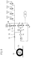
- Fig. 8 shows a level control system, the pressure medium connection 72 for external devices and has facilities. A system in the manner of FIG. 1 is again shown.
- the pressure medium connection 72 can, however, in all of the invention Level control systems are used.
- the pressure medium line 70 leading to the pressure medium connection 72 branches off from the Pressure fluid line 2 from.
- the pressure medium connection 72 has a closure that only then is open when an external device is connected, so that no air from the system can escape or the user is relieved of the task, the line through e.g. to close a tap.
- the external device in FIG. 8 is a tire inflation connection 71, via which a tire 73 can be inflated.
- the tire inflation port 71 is provided with a valve that only opens when the tire inflation connection 71 is connected to a tire 73.
- the suction valve 30 and the valve 3a are opened and the Compressor 8 switched on. Air from the environment thus becomes in the tires 73 promoted.
- the air dryer 10 is not flowed through, because for filling the Tire no dry air is needed. An unnecessary load on the dryer and obstruction of the flow can thus be avoided.
- the embodiment of the invention according to FIG. 8 thus makes certain components of the Level control system can be used for additional purposes without changing the main functions the level control system would be affected in any way.
- FIG. 9 shows a level control system which largely corresponds to that in FIG corresponds to the level control system shown in Figure 2.
- a further controllable directional valve 5 compared to that shown in FIG Compressed air line 3 between the controllable directional valve 4a and the air springs 6a-6d arranged.
Landscapes
- Engineering & Computer Science (AREA)
- Mechanical Engineering (AREA)
- Vehicle Body Suspensions (AREA)
Abstract
Description
Die Erfindung betrifft eine geschlossene Niveauregelanlage für Fahrzeuge gemäß dem
Oberbegriff des Anspruchs 1.The invention relates to a closed level control system for vehicles according to the
Preamble of
Eine derartige Niveauregelanlage ist aus der DE 199 59 556 C1 bekannt. Die aus dieser Druckschrift bekannte Niveauregelanlage weist einen Lufttrockner auf, über den Luft mit Hilfe des Kompressors aus der Atmosphäre angesaugt und zum Leckage-Ausgleich in den Druckmittelvorratsbehälter überführt werden kann. Zur Regeneration des Lufttrockners kann aus dem Druckmittelvorratsbehälter Druckluft über den Lufttrockner in die Atmosphäre abgelassen werden. Durch die Integration des Lufttrockners in die Niveauregelanlage ist weitgehend sichergestellt, dass sich in der Niveauregelanlage entfeuchtete Luft befindet, so dass die Bestandteile der Niveauregelanlage vor Korrosion und Vereisung geschützt sind. Es ist jedoch festzustellen, dass bei der aus der Druckschrift bekannten Niveauregelanlage der Lufttrockner direkt der Atmosphäre zugewandt ist, so dass er ständig Luftfeuchtigkeit aus dieser aufnimmt. Dies kann unter Umständen dazu führen, dass der Lufttrockner seine Funktion nicht oder nicht ausreichend erfüllt. Dieses Problem könnte dadurch gelöst werden, dass der Lufttrockner entsprechend dimensioniert wird, was jedoch zu einem komplizierten Aufbau und hohen Kosten des Lufttrockners führen würde.Such a level control system is known from DE 199 59 556 C1. The one from this Known level control system has an air dryer, over the air with With the help of the compressor sucked out of the atmosphere and for leakage compensation in the Pressure fluid reservoir can be transferred. For regeneration of the air dryer can compressed air from the pressure medium reservoir via the air dryer into the Atmosphere. By integrating the air dryer into the Level control system is largely ensured that dehumidified in the level control system Air is located so that the components of the level control system from corrosion and Icing are protected. However, it should be noted that in the publication known level control system of the air dryer directly faces the atmosphere, so that it constantly absorbs humidity from it. This can possibly do so cause the air dryer not to perform its function or to perform it insufficiently. This The problem could be solved by dimensioning the air dryer accordingly becomes, however, a complicated structure and high cost of the air dryer would lead.
Der Erfindung liegt die Aufgabe zu Grunde, eine geschlossene Niveauregelanlage zu schaffen, die einen Lufttrockner aufweist, der immer zur Lufttrocknung zur Verfügung steht und der darüber hinaus einen einfachen Aufbau aufweisen kann.The invention is based on the object of a closed level control system create that has an air dryer that is always available for air drying stands and which can also have a simple structure.
Die Aufgabe wird durch die kennzeichnenden Merkmale des Anspruchs 1 gelöst. The object is achieved by the characterizing features of
Ein Vorteil der Erfindung ist darin zu sehen, dass der Lufttrockner in einer Druckluftleitung der Niveauregelanlage angeordnet und zumindest durch das Ansaugventil bzw. durch das Ablassventil vollständig von der Atmosphäre abgeschirmt ist. Somit ist der Gefahr vorgebeugt, dass der Lufttrockner ständig Luftfeuchtigkeit aus der Atmosphäre aufnimmt. Ein weiterer Vorteil der Erfindung ist darin zu sehen, dass der Lufttrockner auf der Kompressorausgangsseite (d.h. auf der Druckseite des Kompressors) angeordnet ist, was zu einer besonders hohen Effektivität des Lufttrockners während des Trocknungsbetriebs führt. Aus diesem Grunde kann der Lufttrockner einen einfachen Aufbau und ein klein dimensioniertes Trocknerbett aufweisen. Ein weiterer Vorteil der Erfindung ist darin zu sehen, dass, obwohl der Lufttrockner vollständig in die geschlossene Niveauregelanlage integriert ist, Druckluft aus dem Druckluftvorratsbehälter über den Lufttrockner (zu dessen Regeneration) in die Atmosphäre abgelassen werden kann. Ein weiterer Vorteil der Erfindung ist schließlich darin zu sehen, dass der Lufttrockner während des Regenerationsbetriebs in der entgegengesetzten Richtung durchströmt wird als während des Trocknungsbetriebs. Dadurch ist eine gute Regeneration des Trockners gewährleistet (Näheres siehe Figurenbeschreibung).An advantage of the invention is that the air dryer is in a compressed air line the level control system and at least through the intake valve or is completely shielded from the atmosphere by the drain valve. Thus the Preventing the risk that the air dryer constantly releases atmospheric moisture receives. Another advantage of the invention is that the air dryer is on the compressor outlet side (i.e. on the pressure side of the compressor) is arranged, which leads to a particularly high effectiveness of the air dryer during the Drying operation leads. For this reason, the air dryer can be a simple one Structure and a small sized dryer bed. Another advantage of Invention can be seen in the fact that, although the air dryer is completely closed Level control system is integrated, compressed air from the compressed air reservoir via the Air dryer (for its regeneration) can be released into the atmosphere. On Another advantage of the invention is that the air dryer is flowed through in the opposite direction during the regeneration operation than during the drying operation. This is a good regeneration of the dryer guaranteed (for details see figure description).
Anspruch 2 betrifft ein erstes Ausführungsbeispiel der Erfindung, das im Zusammenhang
mit der Figur 1 näher erläutert wird. Der Vorteil des Ausführungsbeispiels ist darin zu
sehen, dass in den vier Druckluftleitungen ausschließlich 2/2-Wegeventile angeordnet sind,
die einen einfachen Aufbau aufweisen und preiswert sind.
Anspruch 3 betrifft ein weiteres Ausführungsbeispiel der Erfindung, das im
Zusammenhang mit der Figur 2 näher erläutert wird. Der Vorteil des Ausführungsbeispiels
ist darin zu sehen, dass in den vier Druckluftleitungen nur zwei 3/2-Wegeventile angeordnet
sind, die einen einfachen Aufbau aufweisen und preiswert sind.
Gemäß einer Weiterbildung nach Anspruch 4 der oben genannten Ausführungsbeispiele enden die erste Druckluftleitung, die von dem Druckluftbehälter ausgeht, und die dritte Druckluftleitung, die von den Druckmittelkammern ausgeht, in einem gemeinsamen Punkt, der unmittelbar mit dem Kompressoreingang verbunden ist. Der Vorteil dieser Weiterbildung ist darin zu sehen, dass ausgehend von dem gemeinsamen Punkt die erste Druckluftleitung und die dritte Druckluftleitung in einer gemeinsamen Druckluftleitung auf den Kompressoreingang gerührt werden und somit der Bedarf an Druckluftleitungen reduziert wird.According to a development according to claim 4 of the above embodiments the first compressed air line, which extends from the compressed air tank, and the third end Compressed air line, which starts from the pressure medium chambers, in a common point, which is directly connected to the compressor input. The advantage of this Further training can be seen in the fact that, starting from the common point, the first Compressed air line and the third compressed air line in a common compressed air line to the compressor inlet and thus the need for compressed air lines is reduced.
Eine Weiterbildung der Erfindung nach Anspruch 5 ist dadurch gekennzeichnet, dass
- in der ersten Druckluftleitung zwischen dem gemeinsamen Punkt und dem steuerbaren Wegeventil, mit dem die erste Druckluftleitung durchschaltbar ist, ein zum Kompressoreingang hin öffnendes Rückschlagventil liegt, und dass
- in der dritten Druckluftleitung zwischen dem gemeinsamen Punkt und dem steuerbaren Wegeventil, mit dem die dritte Druckluftleitung durchschaltbar ist, ein weiteres zum Kompressoreingang hin öffnendes Rückschlagventil liegt.
- In the first compressed air line between the common point and the controllable directional valve, with which the first compressed air line can be switched through, there is a check valve that opens towards the compressor inlet, and that
- In the third compressed air line between the common point and the controllable directional valve with which the third compressed air line can be switched through, there is a further check valve which opens towards the compressor inlet.
Der Vorteil dieser Weiterbildung ist darin zu sehen, dass in einer bestimmten Stellung der beiden 3/2-Wegeventile ein Überströmen von Druckluft aus den Druckmittelkammern in den Druckmittelvorratbehälter unmöglich ist, und zwar unabhängig davon, ob der Luftdruck in den Druckmittelkammern größer oder kleiner ist als der Luftdruck in dem Druckmittelvorratbehälter. Im Ruhezustand der Niveauregelanlage, wenn also keine Regelung erfolgt, können die steuerbaren Wegeventile beispielsweise in diese Stellung überführt werden, so dass ein unbeabsichtigtes Überströmen von Druckluft zwischen den Druckmittelkammern und dem Druckmittelvorratbehälter nicht stattfinden kann. Darüber hinaus wird durch einen derartigen definierten Zustand der steuerbaren Wegeventile eine Druckmessung des Druckes in den Druckmittelkammern mit Hilfe eines Drucksensors auf einfache Art und Weise möglich (Näheres siehe Ausführungen zu Fig. 2). Die mit der Weiterbildung erreichten Voreile werden bei Erhalt sämtlicher Funktionen der Niveauregelanlage erreicht. Insbesondere ist es weiterhin möglich, aus dem Druckmittelvorratbehälter über den Lufttrockner Druckluft in die Atmosphäre abzuführen, um den Lufttrockner zu regenerieren (Näheres siehe Ausführungen zu Fig. 2).The advantage of this training is the fact that in a certain position the overflow of compressed air from the pressure medium chambers in both 3/2-way valves the pressure medium reservoir is impossible, regardless of whether the Air pressure in the pressure medium chambers is greater or less than the air pressure in the Pressure fluid reservoir. In the idle state of the level control system, so if none Regulation takes place, the controllable directional valves can for example be in this position be transferred so that an unintentional overflow of compressed air between the Pressure medium chambers and the pressure medium reservoir can not take place. About that In addition, such a defined state of the controllable directional valves Pressure measurement of the pressure in the pressure medium chambers with the help of a pressure sensor simple way possible (for details see explanations on Fig. 2). The one with the Advantages achieved in continuing education are retained when all functions of the Level control system reached. In particular, it is still possible from the Discharge the pressure medium reservoir via the air dryer into the atmosphere, to regenerate the air dryer (for details, see explanations on Fig. 2).
Gemäß einer Weiterbildung nach Anspruch 6 der oben genannten Ausführungsbeispiele weist die Niveauregelanlage ein weiteres steuerbares Wegeventil auf, welches die Verbindung zwischen den Luftfedern und dem Kompressor und Lufttrockner sperrt, aber eine Verbindung zwischen den Luftfedern und dem Drucksensor zulässt. Ein Luftaustausch und damit ein Druckausgleich zwischen dem Lufttrockner bzw. Kompressor und den Luftfeder, z.B. bei einer Druckmessung in einer Luftfeder, kann, wenn das Druckniveau des Lufttrockners bzw. Kompressors und der jeweiligen Luftfeder unterschiedlich ist, aufgrund des Volumens des Lufttrockners bzw. Kompressors zu einer Druckänderung in der jeweiligen Luftfeder führen, welche eine Schiefstellung des Fahrzeuges erzeugt und damit eine Nachregelung des Fahrzeugniveaus notwendig macht. Der Vorteil der Weiterbildung der Erfindung ist, dass bei einer Druckmessung in einer Luftfeder unabhängig vom Schaltzustand der beiden 3/2-Wegeventile keine Luft in den Lufttrockner bzw. Kompressor entweichen kann und damit keine Druckänderung in der jeweiligen Luftfeder stattfindet, da das zusätzliche steuerbare Wegeventil diese Verbindung sperrt, und somit keine Schiefstellung des Fahrzeuges erzeugt wird und keine Nachregelung des Fahrzeugniveaus nach einer Druckmessung in einer Luftfeder notwendig ist.According to a development according to claim 6 of the above-mentioned embodiments the level control system has a further controllable directional valve, which the Connection between the air springs and the compressor and air dryer blocks, however allows a connection between the air springs and the pressure sensor. On Air exchange and thus pressure equalization between the air dryer or compressor and the air spring, e.g. when measuring pressure in an air spring, if that Pressure level of the air dryer or compressor and the respective air spring is different, due to the volume of the air dryer or compressor to one Change in pressure in the respective air spring, which causes an inclination of the Vehicle generated and thus a readjustment of the vehicle level is necessary. The advantage of the development of the invention is that with a pressure measurement in one Air spring regardless of the switching state of the two 3/2-way valves, no air in the Air dryer or compressor can escape and therefore no pressure change in the respective air spring takes place because the additional controllable directional valve this Connection blocks, and thus no misalignment of the vehicle is generated and none Readjustment of the vehicle level after a pressure measurement in an air spring necessary is.
Gemäß einer Weiterbildung nach Anspruch 7 des ersten Ausführungsbeispiels ist die Ablassleitung mit der Ansaugleitung verbunden, wobei zwischen dem Punkt, in dem die Ablassleitung von der vierten Druckluftleitung abzweigt und dem Punkt, in dem sie mit der Ansaugleitung verbunden ist, ein Wegeventil angeordnet ist, das in einem ersten Schaltzustand die Ablassleitung sperrt und in einem zweiten Schaltzustand die Ablassleitung durchschaltet, so dass das Ansaugventil gleichzeitig als Ablassventil genutzt werden kann. Der Vorteil dieser Weiterbildung des ersten Ausführungsbeispiels ist darin zu sehen, dass kein separates Ansaugventil bereitgestellt zu werden braucht.According to a development according to claim 7 of the first embodiment, the Drain line connected to the suction line, between the point at which the Drain line branches off from the fourth compressed air line and the point at which it connects with the Suction line is connected, a directional control valve is arranged, which is in a first switching state blocks the drain line and switches the drain line through in a second switching state, so that the suction valve can also be used as a drain valve. The The advantage of this development of the first exemplary embodiment is that no separate suction valve needs to be provided.
Gemäß einer Weiterbildung der Erfindung nach Anspruch 8 liegt das Ansaugventil in einer
Druckluftleitung, die von der zweiten gemeinsamen Druckluftleitung abzweigt. Der
Vorteil dieser Weiterbildung ist darin zu sehen, dass das Ansaugventil in unmittelbarer
Nähe derjenigen Ventile liegt, die den einzelnen Druckmittelkammern vorgeschaltet sind. According to a development of the invention according to
Gemäß einer Weiterbildung der Erfindung nach Anspruch 9 stimmt die Ablassleitung zwischen dem Punkt, in dem sie von der vierten Druckluftleitung abzweigt, und dem Punkt, in den sie mit der Ansaugleitung verbunden ist, mit der zweiten Druckluftleitung überein. Der Vorteil dieser Weiterbildung ist darin zu sehen, dass die zweite Druckluftleitung bereichsweise doppelt genutzt wird (nämlich einmal als Ablassleitung und einmal als Verbindungsstück des Druckmittelvorratsbehälters mit den Druckmittelkammern), so dass die Länge der Druckluftleitungen in der Niveauregelanlage reduziert werden kann.According to a development of the invention according to claim 9, the drain line is correct between the point where it branches off from the fourth air line and the Point where it is connected to the suction line with the second compressed air line match. The advantage of this training is that the second Compressed air line is used twice in some areas (namely once as a discharge line and once as a connector of the pressure medium reservoir with the Pressure medium chambers), so that the length of the compressed air lines in the level control system can be reduced.
Anspruch 10 betrifft ein weiteres Ausführungsbeispiel der Erfindung, das im
Zusammenhang mit der Figur 3 näher erläutert wird.
Gemäß einer Weiterbildung der Erfindung nach Anspruch 11 ist in der vierten Druckluftleitung zwischen dem Lufttrockner und dem Druckmittelvorratsbehälter ein zum Lufttrockner hin öffenendes Rückschlagventil angeordnet, das von einer Druckluftleitung, in der eine Drossel angeordnet ist, überbrückt wird. Der Vorteil dieser Weiterbildung ist darin zu sehen, dass während des Überführens von Druckluft aus dem Druckmittelvorratsbehälter über den Lufttrockner in die Atmosphäre die Druckluft über die Drossel geführt wird, so dass sie vor Eintritt in den Lufttrockner entspannt wird. Dadurch ist eine besonders gute Regeneration des Lufttrockners gewährleistet und es braucht nur eine geringe Luftmenge abgelassen zu werden, um diesen vollständig zu regenerieren. Dennoch ist gewährleistet, dass Druckluft schnell aus den Druckmittelkammern in den Druckmittelvorratsbehälter überführt werden kann (so dass ein schnelles Absenken des Fahrzeugaufbaus möglich ist), da in diesem Fall die Druckluft ausgehend von dem Lufttrockner über das Rückschlagventil in den Druckmittelvorratsbehälter überführt wird (Näheres siehe Figurenbeschreibung).According to a development of the invention according to claim 11, the fourth Compressed air line between the air dryer and the pressure medium reservoir Air dryer opening check valve arranged by a compressed air line, in which a choke is arranged, is bridged. The advantage of this training is to be seen in the fact that during the transfer of compressed air from the pressure medium reservoir the compressed air via the throttle via the air dryer into the atmosphere is guided so that it is relaxed before entering the air dryer. This is one ensures particularly good regeneration of the air dryer and only one is required small amount of air to be discharged to fully regenerate it. Yet It is ensured that compressed air quickly from the pressure medium chambers into the pressure medium reservoir can be transferred (so that a quick lowering of the vehicle body is possible), because in this case the compressed air starts from the air dryer is transferred to the pressure medium reservoir via the check valve (for more information see Figure description).
Gemäß einer Weiterbildung der Erfindung nach Anspruch 12 weist die Niveauregelanlage
einen Drucksensor auf, der in einer von den Druckmittelkammern ausgehenden Druckluftleitung
angeordnet ist, wobei sich zwischen jeder Druckmittelkammer und dem Drucksensor
ein steuerbares Wegeventil befindet, das in einem ersten Schaltzustand die Druckmittelkammern
von dem Drucksensor trennt und in einem zweiten Schaltzustand die
Druckmittelkammer mit dem Drucksensor verbindet. Der Vorteil dieser Weiterbildung ist
darin zu sehen, dass mit dem Drucksensor auf einfache Art und Weise der Druck in den
Druckmittelkammern gemessen werden kann. Darüber hinaus ist es ebenfalls möglich, mit
Hilfe des Drucksensors den Druck in den Druckmittelvorratsbehälter zu messen (Näheres
siehe Figurenbeschreibung).According to a development of the invention according to
Bei den Niveauregelanlagen der eingangs genannten Art besteht ferner das Bedürfnis, die Regelvorgänge möglichst schnell durchzuführen. Dies betrifft nicht nur Regelvorgänge während der Fahrt, sondern auch solche im Stillstand des Fahrzeuges oder bei der Fahrt mit geringer Geschwindigkeit. Dabei müssen oft große Höhenunterschiede bewältigt werden. So besteht bei relativ hoch gebauten Fahrzeugen wie z.B. den sog. Sports Utility Vehicles der Wunsch, das Fahrzeug beim Anhalten abzusenken, um so ein bequemes Einund Aussteigen von Fahrer und Beifahrer zu ermöglichen, und das Fahrzeug bei Fahrtantritt wieder auf eine für die Fahrt optimale Höhe zu heben. Bei herkömmlichen Niveauregelanlagen dauert es relativ lange, bis die Luft aus allen Druckmittelkammern abgezogen ist, so dass die Fahrgäste gezwungen sind, nach Anhalten des Fahrzeuges zu warten, ehe sie dieses auf bequeme Weise verlassen können. Geschlossene Niveauregelanlagen sind hier bereits im Vorteil gegenüber offenen Systemen, bei denen die Luft nur langsam über den Lufttrockner abströmen kann. Durch Weiterbildungen der Erfindung gemäß den Unteransprüche 9 ― 14 sollen weitere Verbesserungen in dieser Hinsicht erreicht werden.In the level control systems of the type mentioned above, there is also the need to Carry out control processes as quickly as possible. This does not only affect control processes while driving, but also those when the vehicle is stationary or while driving at slow speed. Large differences in height often have to be mastered become. For example, in relatively tall vehicles such as the so-called Sports Utility Vehicles the desire to lower the vehicle when stopping in order to comfortably get in and out Allowing the driver and front passenger to get out and the vehicle at Raise the start of the journey to an optimal height for the journey. With conventional Level control systems take a relatively long time to get the air out of all pressure medium chambers is withdrawn so that passengers are forced to stop after stopping the vehicle wait before you can leave it comfortably. Closed level control systems are already at an advantage over open systems where the air only can flow slowly over the air dryer. Through further developments of the invention according to subclaims 9-14 are intended to provide further improvements in this regard can be achieved.
Gemäß einer Weiterbildung der Erfindung nach Anspruch 13 ist die Niveauregelanlage mit
mehreren Kompressoren ausgestattet, wobei jeder Kompressor für sich auf die vorgehend
beschriebene Weise mit dem Druckmittelvorratsbehälter und mit bestimmten Druckmittelkammern
verbunden ist. Somit ist nicht mehr ein einziger Kompressor für die gesamte
Anlage mit allen Druckmittelkammern zuständig, sondern ein einzelner Kompressor hat
jeweils nur einen Teil der Druckmittelkammern, im Extremfall sogar nur eine einzige
Druckmittelkammer, zu versorgen. Mehrere Kompressoren können gleichzeitig den
Druckmittelkammern Luft zuführen oder Luft aus den Druckmittelkammern abziehen. Bei
einem derartigen Parallelbetrieb können diese Vorgänge sehr viel schneller erfolgen als bei
herkömmlichen Niveauregelanlagen, bei denen die gesamte Luft über einen einzigen
Kompressor geführt wird. Die Weiterbildung der Erfindung nach Anspruch 9 hat somit den
Vorteil, dass man mit ihr Niveauänderungen des Fahrzeuges schneller herbeiführen kann
als mit einer herkömmlichen Niveauregelanlage. Die Weiterbildung der Erfindung nach
Anspruch 9 hat ferner den Vorteil, dass einem Teil der Druckmittelkammern Luft
zugeführt und zur gleichen Zeit Luft aus anderen Druckmittelkammern abgezogen werden
kann und Luft zwischen einzelnen Druckmittelkammern oder Gruppen von Druckmittelkammern
ausgetauscht werden kann. Gegenüber einer Anlage gemäß den Ansprüchen 1
bis 8, die zwar ein individuelles Ansteuern der einzelnen Luftfedern ermöglicht, aber nur
entweder im Betrieb "Auffüllen" oder im Betrieb "Entleeren", nicht jedoch in beiden
Betriebsarten gleichzeitig, ergibt sich dadurch der Vorteil erweiterter Steuerungsmöglichkeiten.
Bei dieser Anlage sind daher gute Möglichkeiten gegeben, weitere
Programme zur Steuerung und Regelung des Fahrwerkes, die über eine Regelung des
Niveaus hinausgehen können, umzusetzen.According to a development of the invention according to claim 13, the level control system is included
equipped with several compressors, with each compressor going forward on its own
described way with the pressure medium reservoir and with certain pressure medium chambers
connected is. So there is no longer a single compressor for the whole
System with all pressure medium chambers responsible, but has a single compressor
only a part of the pressure medium chambers, in extreme cases only one
Pressure medium chamber to supply. Multiple compressors can simultaneously
Supply air to the pressure medium chambers or extract air from the pressure medium chambers. at
Such operations can be carried out much more quickly than in parallel operation
conventional level control systems, in which all the air over a single
Compressor is guided. The development of the invention according to claim 9 thus has the
Advantage that you can bring about changes in the level of the vehicle faster
than with a conventional level control system. The further development of the invention
Claim 9 also has the advantage that part of the pressure medium chambers air
supplied and at the same time air is withdrawn from other pressure medium chambers
can and air between individual pressure medium chambers or groups of pressure medium chambers
can be exchanged. Compared to a system according to
Gemäß der Ausführungsform nach Anspruch 14 ist den Druckmittelkammern jeder Achse,
gemäß der Ausführungsform nach Anspruch 15 sogar den Druckmittelkammern jeden
Rades des Fahrzeuges ein eigener Kompressor zugeordnet. Die Ausführungsform nach
Anspruch 10 hat dabei den Vorteil, dass rasche Druckänderungen bereits mit geringem
Aufwand erreichbar sind. Bei einem Fahrzeug mit zwei Achsen kann eine Verdoppelung
der Geschwindigkeit bei Niveauänderungen gegenüber herkömmlichen Anlagen mit nur
einem Kompressor erreicht werden. Die Ausführungsform nach Anspruch 11 hat den
Vorteil, dass noch schnellere Reaktionen möglich sind, und dass zudem bei jedem Rad
individuelle Regulierungen völlig unabhängig von den anderen Druckmittelkammern
vorgenommen werden können.According to the embodiment according to
Gemäß einer Weiterbildung der Erfindung nach Anspruch 16 sind für die gesamte Niveauregelanlage nur ein Lufttrockner sowie eine Ansaug- und eine Ablassleitung mit den zugehörigen Ventilen vorgesehen. Diese Ausrührungsform hat den Vorteil, dass der bauliche Aufwand gering gehalten wird. Es liegt ihr die Erkenntnis zugrunde, dass bei einer geschlossenen Niveauregelanlage ein Luftaustausch mit der Umgebung in nur geringem Maße stattfindet, und dass alle Komponenten der Anlage über den Druckmittelvorratsbehälter miteinander in Verbindung stehen.According to a development of the invention according to claim 16 are for the whole Level control system with only one air dryer as well as an intake and a discharge line the associated valves. This embodiment has the advantage that the construction effort is kept low. It is based on the realization that a closed level control system an air exchange with the environment in only takes place to a small extent, and that all components of the system via the pressure medium reservoir communicate with each other.
Gemäß einer Weiterbildung der Erfindung nach Anspruch 17 sind den Druckmittelkammern
der einzelnen Fahrzeugachsen jeweils eigene Zwischenspeicher für das
Druckmittel zugeordnet. Beim Absenken des Fahrzeuges können diese Zwischenspeicher
in kurzer Zeit große Mengen Luft aus den Druckmittelkammern aufnehmen, wodurch ein
schnelles Absenken des Fahrzeuges ermöglicht wird. Von den Zwischenspeichern kann die
Luft dann über den Kompressor in den Druckmittelvorratsbehälter gefördert werden,
wobei dieser Transport der Luft langsam erfolgen kann, ohne dass dadurch das Absenken
des Fahrzeuges verlangsamt würde. Bei der Anlage nach Anspruch 16 wird durch die
Zwischenspeicher das Entleeren der Druckmittelkammern zur Niveauabsenkung des
Fahrzeuges von der Strömung des Druckmittels in den übrigen Teilen der Anlage, zu der
der Kompressor, die Ventile und relativ lange Leitungssysteme gehören, zeitlich
entkoppelt. Es ist ein schnelles Entleeren der Druckmittelkammern möglich, ohne dass die
gesamte Anlage für eine schnelle Verschiebung großer Luftmassen ausgelegt zu sein
braucht. Im Vergleich zu den alternativen Ausführungsformen nach den Ansprüchen 12 bis
15 hat diese Ausführungsform den Vorteil, dass nur ein einziger Kompressor erforderlich
ist.According to a development of the invention according to claim 17, the pressure medium chambers
The individual vehicle axles each have their own buffer for the
Assigned pressure medium. When lowering the vehicle, these buffers can be used
absorb large amounts of air from the pressure medium chambers in a short time, creating a
rapid lowering of the vehicle is made possible. From the buffers, the
Air is then fed into the pressure medium reservoir via the compressor,
this air can be transported slowly without lowering
of the vehicle would be slowed down. In the system according to claim 16 by
Intermediate storage the emptying of the pressure medium chambers for lowering the level
Vehicle from the flow of the pressure medium in the other parts of the system to which
the compressor, which includes valves and relatively long piping systems, in time
decoupled. It is possible to quickly empty the pressure medium chambers without the
entire system to be designed for rapid displacement of large air masses
needs. In comparison to the alternative embodiments according to
Vorzugsweise sind die Ausgangsleitungen der Zwischenspeicher mit Rückschlagventilen versehen, die ein ungehindertes Abströmen des Druckmittels aus dem Zwischenspeicher zulassen, eine Zuströmung der Luft aus der Anlage jedoch verhindern. Auf diese Weise wird erreicht, dass der Druck in den Zwischenspeichern stets geringer als in den Druckmittelkammern ist.The output lines of the intermediate store are preferably with check valves provided an unimpeded outflow of the pressure medium from the buffer allow, but prevent the inflow of air from the system. In this way the result is that the pressure in the intermediate stores is always lower than in the Pressure medium chambers.
Gemäß einer Weiterbildung der Erfindung nach Anspruch 19 ist den einzelnen Druckmittelkammern jeweils ein Wegeventil zugeordnet, das mit den zum Eingang des Kompressors führenden Druckmittelleitungen verbunden ist. Durch diese Ventile wird eine Steuerung zum Ausgleich von Nick- und Wankbewegungen des Fahrzeuges ermöglicht, wie weiter unten näher erläutert ist.According to a development of the invention according to claim 19, the individual pressure medium chambers each assigned a directional valve, which with the to the entrance of the Compressor leading fluid lines is connected. Through these valves one Control to compensate for pitch and roll movements of the vehicle, as explained in more detail below.
Gemäß einer Weiterbildung der Erfindung nach Anspruch 20 ist eine zum Anschluß
externer Geräte dienende Leitung vorgesehen, die mit den Druckmittelleitungen verbunden
ist. Diese Weiterbildung der Erfindung hat den Vorteil, dass die Druckluft in der Anlage
für zusätzliche Einrichtungen genutzt werden kann. In vorteilhafter Weise nach Anspruch
21 ist die Leitung zum Anschluß externer Geräte mit einem Verschluß ausgestattet, der nur
dann öffnet, wenn ein externes Gerät an die Leitung angeschlossen ist. Vorzugsweise dient
die nach außen führende Leitung zum Anschluß einer Reifenfüllvorrichtung.According to a development of the invention according to
Gemäß einer Weiterbildung der Erfindung nach Anspruch 23 ist die zum Anschluß dienende Leitung direkt mit dem Kompressorausgang verbunden. Diese Ausführungsform hat den Vorteil, das bei einer bei einer Förderung von aus der Umgebung angesaugter Luft durch den Kompressor zum externen Anschluss der Lufttrocker nicht durchströmt und somit von unnötigen Belastungen befreit wird.According to a development of the invention according to claim 23 is for connection serving line directly connected to the compressor outlet. This embodiment has the advantage that when air is drawn in from the environment not flowed through the compressor for external connection of the air dryer and is thus freed from unnecessary burdens.
Ausführungsbeispiele und weitere Vorteile der Erfindung werden im Zusammenhang mit den nachstehenden Figuren erläutert, darin zeigen:
- Fig. 1
bis 3 - eine Niveauregelanlage in schematischer Darstellung,
- Fig. 4 bis 9
- jeweils eine gegenüber den Fig. 1 und 2 abgewandelte Ausführungsform einer Niveauregelanlage in schematischer Darstellung
- 1 to 3
- a level control system in a schematic representation,
- 4 to 9
- 1 and 2 modified embodiment of a level control system in each case in a schematic representation
Figur 1 zeigt eine Niveauregelanlage in schematischer Darstellung, die
Druckmittelkammern in Form von Luftfedern 6a ― 6b, einen Kompressor 8, einen
Lufttrockner 10 und einen Druckluftvorratsbehälter 12 enthält. Der Druckluftbehälter 12
steht über eine erste Druckluftleitung 1, die über ein erstes Wegeventil 1a geführt wird, mit
dem Kompressoreingang 14 und eine vierte Druckluftleitung 4, in der ein steuerbares 2/2-Wegeventil
4a und der Lufttrockner 10 liegt, mit dem Kompressorausgang 16 in
Verbindung. Zwischen dem Lufttrockner 10 und dem Druckluftvorratsbehälter 12 ist in der
vierten Druckluftleitung 4 ein zum Druckluftvorratsbehälter 12 hin öffnendes
Rückschlagventil 18 angeordnet, das von einer Druckluftleitung 20, in der eine Drossel 22
liegt, überbrückt wird. Die erste Druckluftleitung 1 und die vierte Druckluftleitung 4
werden in einem Punkt 24, der zwischen den steuerbaren 2/2-Wegeventilen 1a und 4a und
dem Druckluftvorratsbehälter 12 liegt, zusammengeführt. Ausgehend von diesem Punkt 24
werden sie in einer gemeinsamen Druckluftleitung 46 zu dem Druckluftvorratsbehälter 12
gerührt.Figure 1 shows a level control system in a schematic representation, the
Pressure medium chambers in the form of air springs 6a - 6b, a
Der Kompressorausgang 16 ist über eine zweite Druckluftleitung 2, die über ein steuerbares
Wegeventil 2a und jeweils ein einer Luftfeder 6a ― 6d zugeordnetes steuerbares
Wegeventil 26a ― 26d geführt wird, mit jeder Luftfeder 6a ― 6d verbindbar. Darüber hinaus
ist der Kompressoreingang 14 über eine dritte Druckluftleitung 3, die über ein steuerbares
Wegeventil 3a und die steuerbaren Wegeventile 26a ― 26d geführt wird, ebenfalls mit jeder
Luftfeder 6a ― 6d verbindbar. Die zweite Druckluftleitung 2 und die dritte Druckluftleitung
3 werden in einem Punkt 28, der zwischen den Wegeventilen 2a und 3a und den Luftfedern
6a ― 6d liegt, miteinander verbunden. Ausgehend von diesem Punkt 28 werden sie über
eine gemeinsame Druckluftleitung 34 und über einzelne Druckluftleitungen 48a ― 48d (die
in den Punkten 38a ― 38d von der gemeinsamen Druckluftleitung 34 abzweigen und in
denen die Wegeventile 26a ― 26d liegen) zu den Luftfedern 6a ― 6d geführt.The
Die 2/2-Wegeventile 1a ― 4a können in einem ersten Ventilblock und die Wegeventile 26a
― 26d und das Ansaugventil 30 (dessen Funktion später erläutert wird) können in einem
zweiten Ventilblock zusammengefasst werden.The 2/2-
In Folgendem wird erläutert, wie in der Niveauregelanlage eine Luftfeder 6a ― 6d über den
Kompressor 8 aus dem Druckluftvorratsbehälter 12 aufgefüllt werden kann (am Beispiel
der Luftfeder 6a). Dazu werden zunächst von einer (nicht gezeigten) Steuereinheit die
Wegeventile 1a, 2a und 26a angesteuert, so dass diese von dem in der Figur 1 gezeigten
ersten Schaltzustand in den zweiten Schaltzustand übergehen. Die Druckluftleitung 1 ist
dann durchgeschaltet, so dass der Druckluftbehälter 12 mit dem Kompressoreingang 14
verbunden ist. Darüber hinaus ist die Druckluftleitung 2 durchgeschaltet, so dass der
Kompressorausgang 16 mit der Luftfeder 6a verbunden ist. Somit kann Druckluft aus dem
Druckluftvorratsbehälter 12 über das Wegeventil 1a, den Kompressor 8, über das
Wegeventil 2a und über das Wegeventil 26a in die Luftfeder 6a überführt werden. Die
Steuereinheit steuert ferner den Kompressor 8 an, so dass dieser beginnt zu laufen und die
Luftfeder 6a aufgefüllt wird. Soll der Auffüllvorgang abgebrochen werden, so werden die
Wegeventile 1a, 2a und 26a von der Steuereinheit nicht weiter bestromt, so dass diese
wieder in den ersten Schaltzustand übergehen. Darüber hinaus wird der Kompressor 8
nicht mehr angesteuert, so dass er nicht mehr läuft.The following explains how an
Im Folgenden wird erläutert, wie aus den Luftfedern 6a ― 6d über den Kompressor 8
Druckluft in den Druckluftvorratsbehälter 12 überführt werden kann (am Beispiel der
Luftfeder 6a). Zunächst werden von der Steuereinheit der Niveauregelanlage die
Wegeventile 26a, 3a und 4a angesteuert, so dass diese von den in der Figur 1 gezeigten
ersten Schaltzustand in den zweiten Schaltzustand übergehen. In diesem Fall ist die
Luftfeder 6a über die Druckluftleitung 3 mit dem Kompressoreingang 14 verbunden.
Darüber hinaus ist der Kompressorausgang 16 über die Druckluftleitung 4 mit dem
Druckluftvorratsbehälter 12 verbunden. Die Luftfeder 6a kann dann über das Wegeventil
26a, das Wegeventil 3a, den Kompressor 8, den Lufttrockner 10, das Rückschlagventil 18
und das Wegeventil 4a in den Druckluftvorratsbehälter 12 entleert werden. Während der
Entleerung wird von der Steuereinheit der Niveauregelanlage der Kompressor 8
angesteuert, so dass dieser beginnt zu laufen und den Entleerungsvorgang unterstützt. Zum
Beendigen des Entleerungsvorganges werden die Wegeventile 26a, 3a und 4a von der
Steuereinheit nicht mehr bestromt, so dass diese wieder in den ersten Schaltzustand
übergehen. Darüber hinaus wird der Kompressor 8 nicht mehr angesteuert, so dass dieser
aufhört zu laufen.The following explains how the air springs 6a - 6d via the
Der Kompressor 8 fördert sowohl während des Auffüllens als auch während des Entleerens
einer Luftfeder 6a ― 6d ausschließlich Druckluft vom Kompressoreingang 14 zum
Kompressorausgang 16, so dass lediglich ein Kompressor benötigt wird, der nur in eine
Richtung Druckluft fördern kann. Das Gleiche gilt für das weiter unten beschriebene
Ausführungsbeispiel. The
Neben den bisher genannten Bestandteilen verfügt die Niveauregelanlage über ein
Ansaugventil 30, das in einer Druckluftleitung liegt, über die der Kompressoreingang 14
mit der Atmosphäre verbindbar ist. Vorzugsweise liegt das Ansaugventil 30 in einer
Druckluftleitung 32, die von der Druckluftleitung 34 in einem Punkt 36 abzweigt, der
zwischen dem Punkt 28 und den Abzweigungen 38a ― 38d zu den Luftfedern 6a ― 6d liegt.
Über das Ansaugventil 30 kann aus der Atmosphäre wie folgt Druckluft über den
Kompressor 8 in den Druckluftvorratsbehälter 12 überführt werden: Zunächst werden von
der Steuereinheit der Niveauregelanlage das Ansaugventil 30, das steuerbare Wegeventil
3a und das steuerbare Wegeventil 4a angesteuert, so dass diese von dem in der Figur 1
gezeigten Grundzustand in ihren Schaltzustand übergehen. Darüber hinaus wird von der
Steuereinheit der Kompressor 8 angesteuert, so dass dieser beginnt zu laufen. Ausgehend
von der Druckluftleitung 32 wird dann über das Ansaugventil 30, das steuerbare
Wegeventil 3a, den Kompressor 8, den Lufttrockner 10, das Rückschlagventil 18 und über
das steuerbare Wegeventil 4a Druckluft aus der Atmosphäre in den
Druckluftvorratsbehälter 12 überführt. In dem Lufttrockner 10 wird die Druckluft dabei
getrocknet, wobei er in einer ersten Richtung (in der Figur von rechts nach links)
durchströmt wird.In addition to the previously mentioned components, the level control system has a
Während des Ansaugvorganges muss verhindert werden, dass die Luftfedern 6a ― 6d mit
der Atmosphäre verbunden sind und dass der Kompressorausgang 16 mit der Atmosphäre
verbunden ist (da der Kompressor 8 ansonsten die aus der Atmosphäre über den
Kompressoreingang 14 angesaugte Luft wieder zurück in die Atmosphäre fördern würde).
Ersteres wird durch die steuerbaren Wegeventile 26a - 26d und Letzteres durch das
steuerbare Wegeventil 2a sichergestellt, die sich während des Ansaugens in den in der
Figur 1 gezeigten Schaltzustand befinden.During the suction process, it must be prevented that the air springs 6a - 6d also
are connected to the atmosphere and that the
Die Niveauregelanlage verfügt ferner über eine Druckluftleitung, die von der vierten
Druckluftleitung 4 in einem Punkt 40 abzweigt, der zwischen dem Kompressorausgang 16
und dem Lufttrockner 10 liegt und über die der Druckluftvorratsbehälter 12 über den
Lufttrockner 10 und über ein Ablassventil mit der Atmosphäre verbindbar ist. In dem
gezeigten Ausführungsbeispiel wird diese Druckluftleitung vom Punkt 40 ausgehend bis
zum Punkt 36 von der Druckluftleitung 2 (die zwischen den Punkten 28 und 36 von der
Druckluftleitung 34 gebildet wird) und ausgehend vom Punkt 36 von der Druckluftleitung
32 gebildet. Als Ablassventil wird bei dem gezeigten Ausführungsbeispiel das
Ansaugventil 30. genutzt. Ein Ablassen von Druckluft aus dem Druckluftvorratsbehälter 12
erfolgt wie folgt: Zunächst wird von der Steuereinheit der Niveauregelanlage das
steuerbare Wegeventil 4a, das steuerbare Wegeventil 2a und das Ansaugventil 30
angesteuert, so dass diese von dem in der Figur 1 gezeigten Grundzustand in ihren
Schaltzustand übergehen. Der Druckluftvorratsbehälter 12 ist dann über das steuerbare
Wegeventil 4a, die Drossel 22, den Lufttrockner 10, das steuerbare Wegeventil 2a und das
Ansaugventil 30 mit der Atmosphäre verbunden, so dass er in diese entleert werden kann.
Während des Ablassvorganges wird der Lufttrockner 10 in der entgegengesetzten Richtung
(also von links nach rechts in der Figur) wie während des Auffüllens aus der Atmosphäre
durchströmt, so dass er besonders effektiv regenerieren kann.The level control system also has a compressed air line from the fourth
Compressed air line 4 branches off at a
Während des Ablassvorganges müssen die Luftfedern 6a ― 6d durch steuerbare
Wegeventile von der Atmosphäre getrennt werden, damit diese nicht unbeabsichtigt
entleert werden. Bei dem gezeigten Ausführungsbeispiel erfolgt dies durch die steuerbaren
Wegeventile 26a ― 26d. Zur Beendigung des Ablassvorganges werden die Wegeventile 4a,
2a und 30 von der Steuereinheit nicht mehr bestromt, so dass diese wieder in ihren
Grundzustand übergehen.During the lowering process, the air springs 6a - 6d must be controlled
Directional valves are separated from the atmosphere so that they do not accidentally
be emptied. In the embodiment shown, this is done by the controllable
Schließlich verfügt die Niveauregelanlage in der Druckluftleitung 34 über einen
Drucksensor 42, mit dem der Druck in den Luftfedern 6a ― 6d wie folgt gemessen werden
kann (erläutert an der Luftfeder 6a): Zunächst wird von der Steuereinheit der
Niveauregelanlage das Wegeventil 26a angesteuert, so dass dieses von dem in der Figur 1
gezeigten Grundzustand in seinen Schaltzustand übergeht. Die Luftfeder 6a ist dann mit
dem Drucksensor 42 verbunden, so dass dort der entsprechende Druck gemessen und an
die Steuereinheit der Niveauregelanlage weitergegeben werden kann. Mit Hilfe des
Drucksensors 42 kann ebenfalls der Druck in dem Druckluftvorratsbehälter 12 gemessen.
werden, indem von der Steuereinheit die steuerbaren Wegeventile 1a und 3a angesteuert,
so dass diese von dem in der Figur 1 gezeigten Grundzustand in ihren Schaltzustand
übergehen. Der Druckluftvorratsbehälter 12 ist dann über die steuerbaren Wegeventile 1a
und 3a und über die Druckluftleitung 34 mit diesem verbunden, so dass der entsprechende
Druck gemessen und an die Steuereinheit weitergegeben werden kann.Finally, the level control system in the
Figur 2 zeigt eine Niveauregelanlage, die weitestgehend der in der Figur 1 gezeigten
Niveauregelanlage entspricht. Bei der Niveauregelanlage gemäß Figur 2 sind die in der
Figur 1 gezeigten steuerbaren Wegeventile 1a und 4a in das steuerbare 3/2-Wegeventil 2a
und die in der Figur 1 gezeigten steuerbaren Wegeventile 2a und 3a in das steuerbare 3/2-Wegeventil
4a zusammengefasst. Die Druckluftleitung 1 wird ausgehend von dem
Druckluftbehälter 12 über das steuerbare Wegeventile 2a zu einem Punkt 29 geführt. Die
Druckluftleitung 3 wird ausgehend von den Luftfedern 6a bis 6d über das steuerbare
Wegeventil 4a ebenfalls zu dem Punkt 29 geführt, so dass die Druckluftleitung 1 und die
Druckluftleitung 3 in diesem gemeinsamen Punkt 29 miteinander verbunden sind. Der
gemeinsame Punkt 29 der Druckluftleitungen 1 und 3 ist (ggf. über eine kurze Druckluftleitung
wie auch in der Figur 2 gezeigt) direkt mit dem Kompressoreingang 14 verbunden.
In der ersten Druckluftleitung 1 ist zwischen dem gemeinsamen Punkt 29 und dem
steuerbaren Wegeventil 2a ein zum gemeinsamen Punkt 29 und zum Kompressoreingang
14 hin öffnendes Rückschlagventil 31 angeordnet. In der Druckluftleitung 3 ist zwischen
dem gemeinsamen Punkt 29 und dem steuerbaren Wegeventil 4a ebenfalls ein zum
gemeinsamen Punkt 29 und zum Kompressoreingang 14 hin öffnendes Rückschlagventil
33 angeordnet.FIG. 2 shows a level control system that largely corresponds to that shown in FIG. 1
Level control system corresponds. In the level control system according to Figure 2 are in the
Figure 1 shown controllable
Im Folgenden werden die Funktionen der Niveauregelanlage gemäß Figur 2 erläutert. Zum
Überführen von Druckluft aus der Luftfeder 6a werden zunächst die steuerbaren
Wegeventile 26a und 2a von dem in der Figur 2 gezeigten Schaltzustand in den anderen
Schaltzustand überführt. Die Luftfeder 6a ist dann über die Druckluftleitung 3, in der die
durchgeschalteten Wegeventile 26a und 4a und das Rückschlagventil 33 liegen, mit dem
Kompressoreingang 14 verbunden. Der Kompressorausgang 16 ist über die
Druckluftleitung 4, in der der Lufttrockner 10, das Rückschlagventil 18 und das
durchgeschaltete Wegeventil 2a liegen, verbunden. Die Luft kann also ausgehend von der
Luftfeder 6a mit Hilfe des Kompressors 8 in den Druckluftbehälter 12 überführt werden
(Näheres siehe Fig. 1). Während dieses Vorganges ist die Druckluftleitung 2 durch das
steuerbare Wegeventil 4a und die Druckluftleitung 1 durch das steuerbare Wegeventil 2a
gesperrt. Zur Beendigung des Vorganges wird zumindest das steuerbare Wegeventil 26a
wieder in den in der Figur 2 gezeigten Schaltzustand überführt. Für die Luftfedern 6b bis
6d wird entsprechend vorgegangen, mit dem Unterschied, dass die steuerbaren
Wegeventile 26b bis 26d entsprechende Schaltstellungen einnehmen.The functions of the level control system according to FIG. 2 are explained below. To the
Transfer of compressed air from the
Zum Überführen von Druckluft aus dem Druckluftbehälter 12 in die Luftfeder 6a werden
zunächst die steuerbaren Wegeventile 4a und 26a von dem in der Figur 2 gezeigten
Schaltzustand in den anderen Schaltzustand überführt. Der Druckluftbehälter 12 ist dann
über die Druckluftleitung 1, in der das durchgeschaltete steuerbare Wegeventil 2a und das
Rückschlagventil 31 liegen, mit dem Kompressoreingang 14 verbunden. Der
Kompressorausgang 16 ist über die Druckluftleitung 2, in der das durchgeschaltete
steuerbare Wegeventil 4a und das steuerbare Wegeventil 26a liegen, mit der Luftfeder 6a
verbunden. Es kann also Druckluft von dem Druckluftbehälter 12 über den Kompressor 8
in die Luftfeder 6a überführt werden. Während dieses Vorganges ist die Druckluftleitung 3
durch das steuerbare Wegeventil 4a und die Druckluftleitung 4 durch das steuerbare
Wegeventil 2a gesperrt. Zur Beendigung des Vorganges wird zumindest das steuerbare
Wegeventil 26a wieder in den in der Figur 2 gezeigten Schaltzustand überführt. Die
Luftfedern 6b bis 6d werden auf entsprechende Art und Weise mit Druckluft aus dem
Druckluftbehälter 12 befüllt.To transfer compressed air from the
Zum Auffüllen des Druckluftspeichers 12 mit Luft aus der Atmosphäre werden zunächst
die steuerbaren Wegeventile 30 und 2a von dem in der Figur 2 gezeigten Schaltzustand in
den anderen Schaltzustand überführt. Die Atmosphäre ist dann über das steuerbare Wegeventil
30, das steuerbare Wegeventil 4a und das Rückschlagventil 33 mit dem
Kompressoreingang 14 verbunden. Der Kompressorausgang 16 ist über die
Druckluftleitung 4, in der der Lufttrockner 10, das Rückschlagventil 18 und das durchgeschaltete
steuerbare Wegeventil 2a liegt, mit dem Druckluftbehälter 12 verbunden, so dass
ein Auffüllen des Druckluftbehälter 12 mit Hilfe des Kompressors 8 mit Luft aus der
Atmosphäre möglich ist. Während dieses Vorganges ist die Druckluftleitung 2 durch das
steuerbare Wegeventil 4a und die Druckluftleitung 1 durch das steuerbare Wegeventil 2a
gesperrt. Zur Beendigung des Vorganges wird zumindest das steuerbare Wegeventil 30
wieder in den in der Figur 2 gezeigten Schaltzustand überführt.To fill the
Zum Ablassen von Druckluft aus dem Druckluftbehälter 12 in die Atmosphäre 30 werden
zunächst die steuerbaren Wegeventil 2a, 4a und 30 von dem in der Figur 2 gezeigten
Schaltzustand in den anderen Schaltzustand überführt. Der Druckluftbehälter 12 ist dann
über das steuerbare Wegeventil 2a, die Drossel 22, den Lufttrockner 10, das steuerbare
Wegeventil 4a und das steuerbare Wegeventil 30 mit der Atmosphäre verbunden, so dass
Druckluft aus dem Druckluftvorratsbehälter 12 in diese strömen kann. Hierbei wird die
Druckluft über den Lufttrockner 10 geführt, so dass dieser regeneriert werden kann.To release compressed air from the
Die obigen Ausführungen zeigen, dass die bisher genannten Funktionen der
Niveauregelanlage (Überführen von Druckluft aus den Luftfedern 6a bis 6d in den Druckluftbehälter
12; Überführen von Druckluft aus dem Druckluftbehälter 12 in die Luftfedern
6a bis 6d; Auffüllen des Druckluftbehälters 12 mit Luft aus der Atmosphäre; Ablassen von
Druckluft aus dem Druckluftbehälter 12 über den Lufttrockner 10 in die Atmosphäre)
durch die Rückschlagventile 31 und 33 nicht beeinträchtigt werden.The above explanations show that the functions of the
Level control system (transfer of compressed air from the air springs 6a to 6d into the
Im Folgenden wird erläutert, wie mit Hilfe des Drucksensors 42 der Luftdruck in den
Luftfedern 6a bis 6d gemessen werden kann. Während der Druckmessung soll ein
Luftaustausch zwischen den Luftfedern 6a bis 6d und dem Druckluftbehälter 12 möglichst
vermieden werden, um ein unbeabsichtigtes Absenken bzw. Anheben des Fahrzeugaufbaus
zu vermeiden. Es ist also zu vermeiden, dass während der Druckmessung Druckluft aus
den Luftfedern 6a bis 6d in den Druckluftbehälter überströmt (dies könnte passieren, wenn
der Luftdruck in der zu messenden Luftfeder 6a bis 6d größer ist als der Luftdruck in dem
Druckluftbehälter 12). Es ist ebenfalls zu vermeiden, dass während der Druckmessung
Druckluft aus dem Druckluftbehälter 12 in die Luftfeder 6a bis 6d überströmt, deren
Luftdruck gemessen wird (dies könnte passieren, wenn die Druckluft in der zu messenden
Luftfeder 6a bis 6d kleiner ist als in dem Druckluftbehälter 12). Da vor der Druckmessung
nicht bekannt ist, ob der Luftdruck in der zu messenden Luftfeder 6a bis 6d größer oder
kleiner ist als in dem Druckluftbehälter 12, muss eine Stellung der steuerbaren
Wegeventile eingestellt werden, mit der unabhängig von den Druckverhältnissen beide
möglichen Fälle wirksam unterdrückt werden. Dies wird durch die in der Figur 2 gezeigte
Stellung der steuerbaren Wegeventile 2a und 4a gewährleistet (wie im Folgenden ausgeführt
wird), wobei das steuerbare Wegeventil 2a Druckluftleitung 1 durchschaltet und die
Druckluftleitung 4 sperrt und das steuerbare Wegeventil 4a die Druckluftleitung 3
durchschaltet und die Druckluftleitung 2 sperrt.In the following it will be explained how the air pressure in the
Im Folgenden wird die Druckmessung in einer der Luftfedern 6a bis 6d beispielhaft
anhand der Luftfeder 6a erläutert. Zur Messung des Luftdruckes wird das steuerbare
Wegeventil 26a von dem in der Figur 2 gezeigten Schaltzustand in den anderen Schaltzustand
überführt, so dass die Luftfeder 6a über das steuerbare Wegeventil 26a mit dem
Drucksensor 42 verbunden ist und mit dessen Hilfe der Luftdruck gemessen werden kann.
Wenn hierbei der Luftdruck in der Luftfeder 6a größer ist als der Luftdruck in dem Druckluftbehälter
12, so kann trotzdem keine Druckluft von der Luftfeder 6a in den
Druckluftbehälter 12 überströmen. Die Luft aus der Luftfeder 6a gelangt nämlich über die
steuerbaren Wegeventile 26a und 4a und das Rückschlagventil 33 zu dem
Rückschlagventil 31, das jedoch zu dem steuerbaren Wegeventil 2a hin sperrt. Somit
gelangt die Druckluft nur bis zu dem Rückschlagventil 31, nicht jedoch bis zu dem steuerbaren
Wegeventil 2a und dem Druckluftbehälter 12. Ein Überströmen von Druckluft aus
der Luftfeder 6a in den Druckluftbehälter 12 über einen anderen Weg ist ebenfalls nicht
möglich, da die Druckluftleitungen 2 und 4 durch die steuerbaren Wegeventile 4a und 2a
unterbrochen sind.In the following, the pressure measurement in one of the air springs 6a to 6d becomes an example
explained using the
Wenn hingegen der Luftdruck in dem Druckluftbehälter 12 größer ist als der Luftdruck in
der Luftfeder 6a, so ist es ebenfalls nicht möglich, dass Druckluft von diesem in die
Luftfeder 6a überströmt. In diesem Fall kann die Luft nämlich ausgehend von dem
Druckluftbehälter 12 über das steuerbare Wegeventil 2a und das Rückschlagventil 31 nur
bis zu dem Rückschlagventil 33 gelangen, das zum steuerbaren Wegeventil 4a und zur
Luftfeder 6a hin sperrt. Ein Überströmen von Druckluft aus dem Druckluftbehälter 12 in
die Luftfeder 6a über einen anderen Weg ist ebenfalls nicht möglich, da die Druckluftleitung
4 durch das Wegeventil 2a und die Druckluftleitung 2 durch das Wegeventil 4a
unterbrochen ist.On the other hand, if the air pressure in the
Zur Beendigung der Druckmessung wird das steuerbare Wegeventil 26a wieder in den in
der Figur 1 gezeigten Zustand überführt. Auf entsprechende Art und Weise wird der Luftdruck
in den Luftfedern 6b bis 6d gemessen, wobei dann das entsprechende Wegeventil
26b bis 26d von dem in der Figur 2 gezeigten Schaltzustand in den anderen Schaltzustand
überführt wird.To end the pressure measurement, the controllable
Figur 3 zeigt eine Niveauregelanlage, die weitestgehend der in der Figur 1 gezeigten
Niveauregelanlage entspricht. Ein Unterschied ist darin zu sehen, dass die in der Figur 1
gezeigten schaltbaren Wegeventile 1a ― 4a in zwei steuerbare Wegeventile 2a und 4a
zusammengefasst sind. Die in der Figur 2 gezeigte Niveauregelanlage entspricht bezüglich
ihres generellen Aufbaus der in der DE 199 59 556 C1 gezeigten Niveauregelanlage, so
dass bezüglich des Auffüllens der Luftfedern 6a ― 6d aus dem Druckluftvorratsbehälter 12
und des Überführens von Druckluft aus den Luftfedern 6a ― 6d in den Druckluftvorratsbehälter
12 auf diese Druckschrift verwiesen wird. Die Niveauregelanlage enthält
einen Lufttrockner 10, der in der vierten Druckluftleitung 4 angeordnet ist, über die der
Kompressorausgang 16 über das Wegeventil 4a mit dem Druckluftvorratsbehälter 12
verbindbar ist (die Verbindung ist dann hergestellt, wenn das Wegeventil 4a von dem in
der Figur 3 gezeigten Schaltzustand in seinen anderen Schaltzustand übergeht).FIG. 3 shows a level control system that largely corresponds to that shown in FIG. 1
Level control system corresponds. One difference can be seen in the fact that the in FIG
Switchable
Ausgehend von dem Punkt 28 in Richtung der Luftfedern 6a ― 6d ist die
Niveauregelanlage gemäß Figur 3 genauso aufgebaut wie die Niveauregelanlage gemäß
Figur 1, so dass diesbezüglich auf die obige Figurenbeschreibung verwiesen wird. Über
das Ansaugventil 30 kann wie folgt Druckluft aus der Atmosphäre über den Kompressor 8
in den Druckluftbehälter 12 überführt werden: Zunächst wird von der (nicht gezeigten)
Steuereinheit der Niveauregelanlage das Ventil 30, das Wegeventil 2a und das Wegeventil
4a angesteuert, so dass diese von dem in der Figur 3 gezeigten Schaltzustand in ihren
anderen Schaltzustand übergehen. Daraufhin wird von der Steuereinheit der Kompressor 8
angesteuert, so dass Druckluft aus der Atmosphäre über das Ansaugventil 30, das
Wegeventil 2a, den Kompressor 8, den Lufttrockner 10, das Rückschlagventil 18 und das
Wegeventil 4a in den Druckluftvorratsbehälter 12 überführt wird. Zur Beendigung dieses
Vorganges wird von der Steuereinheit wiederum der Kompressor 8 angesteuert, so dass
dieser aufhört zu laufen und darüber hinaus wird das Ansaugventil 30 nicht mehr bestromt,
so dass dieses wieder in den in der Figur 3 gezeigten Zustand übergeht und zur
Atmosphäre hin sperrt.Starting from
Über das Ablassventil 44 kann zur Regeneration des Lufttrockners 10 Druckluft aus dem
Druckluftvorratsbehälter 12 in die Atmosphäre abgelassen werden. Dazu verfügt die
Niveauregelanlage über eine Druckluftleitung, die von der vierten Druckluftleitung 4 in
einem Punkt 40 abzweigt, der zwischen dem Kompressorausgang 16 und dem Lufttrockner
10 liegt und die über ein Ablassventil 44 mit der Atmosphäre verbindbar ist. Die
Entleerung des Druckluftvorratsbehälters 12 erfolgt wie folgt: Von der Steuereinheit der
Niveauregelanlage werden die Wegeventile 44 und 4a angesteuert, so dass diese von dem
in der Figur 3 gezeigten Schaltzustand in ihren anderen Schaltzustand übergehen. Der
Druckluftvorratsbehälter 12 ist dann über das Wegeventil 4a, die Druckluftleitung mit der
Drossel 22, den Lufttrockner 10 und das Ablassventil 44 mit der Atmosphäre verbunden.
Zur Beendigung des Ablassvorganges wird von der Steuereinheit zumindest das Wegeventil
44 nicht mehr bestromt, so dass dieses wieder in den in der Figur 3 gezeigten
Schaltzustand übergeht und zur Atmosphäre hin sperrt. Während des Ablassvorganges
wird der Lufttrockner in der entgegengesetzten Richtung durchströmt wie während des
Auffüllvorganges des Druckluftvorratsbehälters.Via the
In den Figuren 4 bis 8 sind Ausführungsbeispiele der Erfindung dargestellt, durch die zusätzliche Funktionen der Niveauregelanlage ermöglicht werden. Grundlage sind dabei jedoch immer Anlagen, wie sie in Zusammenhang mit den Figuren 1 bis 3 beschrieben worden sind. In den Ausführungsbeispielen nach den Figuren 4 ― 8 sind Niveauregelanlagen dargestellt, die ähnlich aufgebaut sind wie die im Zusammenhang mit Fig. 1 Beschriebene. Diese Weiterbildungen der Erfindung könnten aber auch in analoger Weise auf Niveauregelanlagen im Sinne von Fig. 2 und 3 aufgebaut sein. In den Figuren 4 bis 8 sind für Komponenten, die gegenüber Fig. 1 nicht verändert worden sind, die gleichen Bezugszeichen beibehalten.In the figures 4 to 8, exemplary embodiments of the invention are shown, through which additional functions of the level control system are made possible. The basis are however, always systems as described in connection with Figures 1 to 3 have been. In the exemplary embodiments according to FIGS. 4-8 are level control systems shown, which are constructed similarly to that in connection with FIG. 1 Described. However, these developments of the invention could also be carried out in an analogous manner be built on level control systems in the sense of FIGS. 2 and 3. In Figures 4 to 8 are the same for components that have not been changed from FIG. 1 Maintain reference numbers.
Fig. 4 zeigt zwei Regelkreise 100 und 200, die beide gleichartig und in gleicher Weise wie
bei Fig. 1 aufgebaut sind. Die Regelkreise 100 und 200 werden aus einem einzigen
Druckmittelvorratsbehälter 12 gespeist. Durch einen der Regelkreise, z.B. 100, werden die
zur Vorderachse des Fahrzeuges gehörenden Druckmittelkammern, z.B. 6a und 6b, und
durch den anderen Regelkreis (in diesem Beispiel 200) die Druckmittelkammern (in
diesem Beispiel 6c und 6d) mit Luft versorgt und gesteuert.Fig. 4 shows two
Beide Regelkreise 100 bzw. 200 haben Kompressoren 108 bzw. 208, deren Eingänge 114
bzw. 214 über Wegeventile 101a bzw. 201a und Druckluftleitungen 101 bzw. 201 mit dem
Druckmittelvorratsbehälter 12 und über Wegeventile 103a bzw. 203a und Druckluftleitungen
103 bzw. 203 mit den Druckmittelkammern 6a und 6b bzw. 6c und 6d der
jeweiligen Fahrzeugachsen in Verbindung stehen. Die Ausgänge 116 bzw. 216 der
Kompressoren 100, 200 sind über Druckluftleitungen 102 bzw. 202 und Wegeventile 102a
bzw. 202a mit den Druckmittelkammern 6a, 6b bzw. 6c, 6d und über Druckluftleitungen
104 bzw. 204 und Wegeventile 104a bzw. 204a mit dem Druckmittelvorratsbehälter 12
verbunden. Die Regelkreise 100 und 200 sind zudem mit Drucksensoren 142 und 242
ausgestattet.Both
In der Druckluftleitung 104 des Regelkreises 100 ist ein Lufttrockner 10 angeordnet, dem
eine Drossel 22 und ein dazu paralleles Rückschlagventil 18 vorgeschaltet sind. Über eine
Leitung 32, die mit einem Ventil 30 versehen ist, kann Luft aus der Umgebung
aufgenommen oder in die Umgebung abgegeben werden. Die Wirkungsweise dieser
Einrichtungen ist dieselbe wie bei Fig. 1. Diese Einrichtungen sind nur im Regelkreis 100,
nicht jedoch im Regelkreis 200 vorgesehen. Dieses ist möglich, da zum einen die
Regelreise 100 und 200 über den Druckmittelvorratsbehälter 12 miteinander in Verbindung
stehen, und da zum anderen bei einer geschlossenen Niveauregelanlage ein Austausch mit
der Umgebung in nur geringem Maße, vor allem zum Ausgleich von Leckageverlusten,
stattfindet. An
Die Anlage nach Fig. 4 stellt somit, abgesehen von den gemeinsam genutzten
Komponenten zum Luftaustausch mit der Umgebung und dem gemeinsam genutzten
Druckmittelvorratsbehälter 12, eine Verdoppelung der Anlage aus Fig. 1 dar. Dieser
erhöhte Aufwand hat jedoch den Vorteil, dass nunmehr jeder Achse eines zweiachsigen
Fahrzeuges eine eigene Einheit zur Luftversorgung und Drucksteuerung der Druckmittelkammern
zur Verfügung steht, die jeweils über einen eigenen Kompressor verfügt. Jeder
Kompressor 108, 208 hat daher nur noch zwei Druckmittelkammern zu versorgen anstatt
vier wie bei der Anlage nach Fig. 1. Wenn beide Kompressoren 108, 208 gleichzeitig
betrieben werden, kann daher bei einer Anlage gemäß Fig. 4 das Füllen und Entleeren der
Druckmittelkammern mit doppelt so hoher Geschwindigkeit erfolgen wie bei einer Anlage
gemäß Fig. 1. Darüber hinaus besteht bei einer Niveauregelanlage gemäß Fig. 4 die
Möglichkeit, die Druckmittelkammern der einen Achse zu füllen und gleichzeitig die
Druckmittelkammern der anderen Achse zu leeren. Durch ein solches Verschieben des
Druckmittels zwischen den Achsen können Nickbewegungen des Fahrzeuges ausgeglichen
werden. Die Niveauregelung gemäß Fig. 4 bietet somit die Möglichkeit, weitere
Programme zur Fahrwerksregelung zu verwirklichen, ohne dass zusätzlicher technischer
Aufwand wie eigens dafür vorgesehene Vorrichtungen, Ventile usw. benötigt werden.The system of Fig. 4 thus, apart from the shared
Components for air exchange with the environment and the shared one
Fig. 4 zeigt eine Niveauregelanlage für ein Fahrzeug mit zwei Achsen. Es versteht sich,
dass für ein Fahrzeug mit mehr als zwei Achsen den Regelkreisen 100 und 200 noch
weitere gleichartige Regelkreise parallel geschaltet werden können, so dass jeder Achse ein
eigener Regelkreis mit Kompressor zugeordnet ist.Fig. 4 shows a level control system for a vehicle with two axes. It goes without saying
that for a vehicle with more than two axles the
Der Gedanke, einzelnen Fahrwerkskomponenten jeweils einen eigenen Kompressor
zuzuordnen, ist bei der in Fig. 5 gezeigten Niveauregelanlage noch weiter geführt , indem
nunmehr jeder Druckmittelkammer 6a ― 6d ein eigener Regelkreis 100, 200, 300 und 400
zugeordnet ist, wobei die Regelkreise 100, 200, 300, 400 wiederum in der vorgehend
beschriebenen Weise aufgebaut sind und jeweils eigene Kompressoren 108, 208, 308 und
408 aufweisen. Damit kann jede zu je einem Fahrzeugrad gehörende Druckmittelkammer
6a-6d individuell und unabhängig von den anderen Druckmittelkammern befüllt oder
entleert werden. Es sind noch schnellere Druckänderungen in den Druckmittelkammern
und eine noch bessere Regelung des Fahrwerkes möglich als bei den bisher beschriebenen
Ausführungsbeispielen der Erfindung. Bei gleichzeitigem, parallelem Betrieb aller
Regelkreise entweder zum Erhöhen oder zum Absenken des Druckes in den Druckmittelkammern
können Niveauänderungen des Fahrzeuges in einem Viertel der Zeit
durchgeführt werden, die bei einer vergleichbaren Anlage mit nur einem einzigen
Kompressor benötigt würde. Durch gleichzeitigen Betrieb der Regelkreise 100, 200, 300
und 400 können zudem weitere Programme zur Fahrwerksregelung, z.B. zum Ausgleich
von Nick- und Wankbewegungen , verwirklicht werden, ohne dass zusätzliche
Vorrichtungen benötigt werden.The idea of individual suspension components each having their own compressor
assign, is further guided in the level control system shown in Fig. 5 by
now each pressure
Die in Fig. 6 dargestellte Niveauregelanlage verfügt über einen Regelkreis von der Art des
in Verbindung mit Fig. 1 beschriebenen. Bei dieser Niveauregelanlage sind die zur Vorderbzw.
zur Hinterachse gehörenden Druckmittelkammern jeweils zu Gruppen 50, 51'
zusammengefasst. Ein mit mehr als zwei Achsen würden entsprechend mehr derartige
Gruppen aufweisen. Zu jeder Gruppe gehört ein Druckmitelspeicher 51, 51'. Die
Druckmittelspeicher 51, 51'stehen über Wegeventile 52a ― 52d mit den jeweiligen
Druckmittelkammern 6a - 6d und über Rückschlagventile 53 und 53' mit dem Punkt 28 der
Versorgungseinheit in Verbindung. Die Ventile 52a ― 52d sind vorzugsweise so ausgebildet,
dass sie große Strömungsquerschnitte freigeben können. Die Rückschlagventile 53
und 53'sperren, ausgehend vom Punkt 28, in Richtung zu den Druckmittelspeichern 51,
51'. Den Druckmittelkammern 6a-6d sind ferner Wegeventile 26a ― 26d vorgeschaltet, die
in Zusammenhang mit Fig. 1 bereits beschrieben worden sind.The level control system shown in Fig. 6 has a control circuit of the type
described in connection with Fig. 1. In this level control system, the front or
pressure medium chambers belonging to the rear axle each in
Den Druckmittelkammern 6a ― 6d kann somit entweder über die Ventile 26a ― 26d und
den Kompressor 8 aus dem Druckmittelvorratsbehälter 12 oder über die Ventile 52a ― 52c
aus den Druckmittelspeichern 51 bzw. 51' Luft zugeführt werden. Das Ablassen von Luft
aus den Druckmittelkammern 6a ― 6d kann in der bereits in Verbindung mit Fig. 1
beschriebenen Weise über die Ventile 26a ― 26d in den Vorratsbehälter 12 erfolgen. Dabei
müssen lange Leitungssysteme mit mehreren Ventilen sowie der Lufttrockner durchströmt
werden, was die Strömungsgeschwindigkeit beeinträchtigt. Das Ablassen der Luft kann
aber auch über die Ventile 52a ― 52d in die Speicher 51 bzw. 51' erfolgen, was wegen der
kurzen Leitungen und bei genügend großen Querschnitten der Ventile 52a ― 52d sehr
schnell von statten gehen kann. Somit ist ein rasches Absenken des Fahrzeuges möglich.The pressure
Die Luft aus den Speichern 51, 51' gelangt über die Rückschlagventile 53, 53' und den
Kompressor 8 ebenfalls zum Vorratsbehälter 12, wobei dieses Abströmen langsam
erfolgen kann, ohne dass Bewegungen des Fahrzeuges davon betroffen sind. Die Speicher
51, 51'dienen somit als Zwischenspeicher oder Puffer, die größere Mengen von Luft
schnell aufnehmen können, um sie dann nach und nach an die langsamer arbeitenden Teile
der Anlage abzugeben. Die Rückschlagventile 53, 53'verhindern, dass bei einem Auffüllen
der Druckmittelkammern 6a ― 6d durch den Kompressor 8 Luft in die Speicher 51,
51' gelangt. Eine derartige Druckerhöhung in den Speichern wäre nicht nur eine unnötige
Verschwendung von Energie, sondern sie würde sogar die Funktion der Anlage
beeinträchtigen. Um ein schnelles Entleeren der Druckmittelkammern 6a ― 6d nach Öffnen
der Ventile 52a bis 52d in die Speicher 51, 51' zu erzielen, muß der Druck in den
Speichern 51, 51' möglichst gering, auf alle Fälle jedoch geringer als in den jeweiligen
Druckmittelkammern sein.The air from the
Fig. 7 zeigt eine Niveauregelanlage mit zusätzlichen Einrichtungen für eine Regelung zum Ausgleich von Nickbewegungen. Als Nickbewegungen werden Bewegungen des Fahrzeuges um eine Achse quer zur Fahrtrichtung bezeichnet. Solche Bewegungen treten z.B. beim Anfahren oder Bremsen auf. In Fig. 7 sind die Einrichtungen zum Nickausgleich in Verbindung mit einer Anlage in der Art von Fig. 1 dargestellten. Diese Einrichtungen könnten aber auch in Verbindung mit einer anderen Ausführungsform der Erfindung verwendet werden.Fig. 7 shows a level control system with additional devices for control Compensation of pitching movements. The movements of the Designated vehicle about an axis transverse to the direction of travel. Such movements occur e.g. when starting or braking. In Fig. 7 are the devices for pitch compensation shown in connection with a system of the type in FIG. 1. These facilities but could also in connection with another embodiment of the invention be used.
Die Druckmittelkammern 6a ― 6d sind über Ventile 26a ― 26d einzeln ansteuerbar und über
das Ventil 2a und die Leitung 2 mit dem Kompressorausgang 16 sowie über das Ventil 3a
und die Leitung 3 mit dem Kompressoreingang 14 verbunden. Zusätzlich sind weitere
schaltbare Wegeventile 60a ― 60d vorgesehen, die jeweils den einzelnen Druckmittelkammern
6a bis 6d vorgeschaltet und mit der ersten bzw. dritten Druckmittelleitung 1 bzw.
3 verbunden sind. Über die Druckmittelleitungen 1 bzw. 3 besteht eine direkte Verbindung
mit dem Kompressoreingang. Mit Hilfe dieser Ventile können Druckmittelkammern
untereinander Druckmittel austauschen.The pressure
Durch eine geeignete Steuerung der Ventile 26a ― 26d, 60a ― 60d sowie 2a und 3a kann
eine Regelung zum Nickausgleich erfolgen, indem über den Kompressor der Druck in den
Druckmittelkammern der einzelnen Achse entsprechend verringert oder erhöht wird.
Wenn z.B. die Vorderachse über die Druckmittelkammern 6a und 6b und die Hinterachse
über die Druckmittelkammern 6c und 6d abgefedert wird und das Fahrzeug z.B. beim
Bremsen die Tendenz hat, vorne abzusinken und hinten in die Höhe zu gehen, werden die
Ventile 60c, 60d, 2a, 26a und 26b durchgeschaltet und durch den Kompressor 8 Luft von
der Druckmittelkammern der Hinterachse 6c, d zu denen der Vorderachse 6a, 6b befördert,
um die Nickbewegung auszugleichen. Wenn in einer umgekehrten Bewegung z.B. beim
Anfahren das Vorderteil des Fahrzeuges nach oben und das Heck nach unten gehen will,
werden die Ventile 60a, 60b, 3a, 26c und 26d geöffnet und Luft durch den Kompressor 8
von der Vorderachse zur Hinterachse befördert. Der Kompressor 8 wird, während er in
Betrieb ist, stets in der gleichen Richtung durchströmt.By suitable control of the
In analoger Weise wie der Nickausgleich könnte mit der Niveauregelanlage nach Fig. 7 auch ein Wankausgleich verwirklicht werden, d.h. ein Ausgleich von Drehbewegungen des Fahrzeuges um seine Längsachse, indem Druckmittel zwischen den auf der linken und auf der rechten Seite des Fahrzeuges liegenden Druckmittelkammern ausgetauscht wird.In a manner analogous to pitch compensation, the level control system according to FIG. 7 a roll compensation can also be implemented, i.e. a compensation of rotary movements of the Vehicle about its longitudinal axis, adding pressure medium between those on the left and on pressure medium chambers lying on the right side of the vehicle is replaced.
Fig. 8 zeigt eine Niveauregelanlage, die einen Druckmittelanschluss 72 für externe Geräte
und Einrichtungen aufweist. Es ist wiederum eine Anlage in der Art von Fig. 1 dargestellt.
Der Druckmittelanschluss 72 kann jedoch bei allen erfindungsgemäßen
Niveauregelanlagen Verwendung finden.Fig. 8 shows a level control system, the
Die zu dem Druckmittelanschluss 72 führende Druckmittelleitung 70 zweigt von der
Druckmittelleitung 2 ab. Der Druckmittelanschluss 72 hat einen Verschluß, der nur dann
geöffnet ist, wenn ein externes Gerät angeschlossen ist, so dass keine Luft aus der Anlage
entweichen kann bzw. der Benutzer von der Aufgabe entlastet wird, die Leitung durch
z.B.Betätigen eines Hahnes zu schließen..The
Die externe Einrichtung ist in Fig. 8 ein Reifenfüllanschluss 71, über den ein Reifen 73
aufgepumpt werden kann. Der Reifenfüllanschluss 71 ist mit einem Ventil versehen, das
nur dann öffnet, wenn der Reifenfüllanschluss 71 mit einem Reifen 73 verbunden ist. Zum
Füllen des Reifens 73 werden das Ansaugventil 30 und das Ventil 3a geöffnet und der
Kompressor 8 eingeschaltet. Es wird somit Luft aus der Umgebung in den Reifen 73
gefördert. Der Lufttrockner 10 wird dabei nicht durchströmt, da für die Befüllung des
Reifens keine trockene Luft benötigt wird. Eine unnötige Belastung des Trockners und
eine Behinderung der Strömung können somit vermieden werden.The external device in FIG. 8 is a tire inflation connection 71, via which a
Die Ausführungsform der Erfindung nach Fig. 8 macht somit bestimmte Komponenten der Niveauregelanlage für zusätzliche Zwecke nutzbar, ohne dass dadurch die Hauptfunktionen der Niveauregelanlage in irgendeiner Weise beeinträchtigt wären.The embodiment of the invention according to FIG. 8 thus makes certain components of the Level control system can be used for additional purposes without changing the main functions the level control system would be affected in any way.
Die Ausführungsform der Figur 9 zeigt eine Niveauregelanlage, die weitestgehend der in
der Figur 2 gezeigten Niveauregelanlage entspricht. Bei der Niveauregelanlage gemäß
Figur 9 ist gegenüber der in Figur 2 gezeigten ein weiters steuerbares Wegeventile 5 in der
Druckluftleitung 3 zwischen dem steuerbaren Wegeventil 4a und den Luftfedern 6a-6d
angeordnet. Somit ist bei geschlossenem Wegeventil 5 eine Druckmessung mit dem
Drucksensor 42 in den Luftfedern 6a-6d ohne einen Luftaustausch und damit
Druckausgleich zwischen der jeweiligen Luftfeder 6a-6d und dem Lufttrockner 10
und/oder dem Kompressor 8 möglich. Die Befüllung oder Entleerung der Luftfedern 6a-6d
oder die Verbindung des Kompressorsausganges 8 oder Kompressorseinganges 14
und/oder Lufttrockners 10 zur Atmosphäre über das steuerbare Wegeventil 30 werden
durch das dann geschaltete Wegeventil 5 nicht beeinflusst. Es ist auch möglich die
Schaltfunktion des steuerbaren Wegeventiles 5 umzukehren, und beispielsweise bei der
Druckmessung das steuerbare Wegeventil 5 zu schalten und bei weiteren Funktionen nicht
zu schalten. The embodiment in FIG. 9 shows a level control system which largely corresponds to that in FIG
corresponds to the level control system shown in Figure 2. With the level control system according to
FIG. 9 is a further controllable
- 11
- erste Druckluftleitungfirst compressed air line
- 22
- zweite Druckluftleitungsecond compressed air line
- 33
- dritte Druckluftleitungthird compressed air line
- 44
- vierte Druckluftleitungfourth compressed air line
- 1a-4a1a-4a
- steuerbares Wegeventilcontrollable directional valve
- 55
- steuerbares Wegeventilcontrollable directional valve
- 6a-6d6a-6d
- Luftfederair spring
- 88th
- Kompressorcompressor
- 1010
- Lufttrocknerair dryer
- 1212
- DruckluftvorratsbehälterCompressed air reservoir
- 1414
- Kompressoreingangcompressor input
- 1616
- Kompressorausgangcompressor output
- 1818
- Rückschlagventilcheck valve
- 2020
- DruckluftleitungCompressed air line
- 2222
- Drosselthrottle
- 2424
- PunktPoint
- 26a-26d26a-26d
- steuerbares Wegeventilcontrollable directional valve
- 2828
- PunktPoint
- 2929
- PunktPoint
- 3030
- Ansaugventilintake valve
- 3131
- Rückschlagventilcheck valve
- 3232
- DruckluftleitungCompressed air line
- 3333
- Rückschlagventilcheck valve
- 3434
- DruckluftleitungCompressed air line
- 3636
- PunktPoint
- 38a-38d38a-38d
- Abzweigungdiversion
- 4040
- PunktPoint
- 4242
- Drucksensor pressure sensor
- 4444
- Ablassventildrain valve
- 4646
- DruckluftleitungCompressed air line
- 48a-48d48a-48d
- DruckluftleitungCompressed air line
- 50, 50'50, 50 '
- Achsgruppenaxis groups
- 51, 51'51, 51 '
- DruckmittelspeicherAccumulator
- 52, 52'52, 52 '
- schaltbare Wegeventileswitchable directional valves
- 53, 53'53, 53 '
- Rückschlagventilecheck valves
- 60a-60d60a-60d
- schaltbare Wegeventileswitchable directional valves
- 7070
- Leitung für externen AnschlußCable for external connection
- 7171
- ReifenfüllgerätTire inflator
- 7272
- Anschluß für externe GeräteConnection for external devices
- 7373
- Reifentires
- 100, 200100, 200
- Regelkreisecontrol loops
- 101-104, 201-204101-104, 201-204
- DruckluftleitungenCompressed air lines
- 101a-104a, 201a-204a101a-104a, 201a-204a
- Wegeventileway valves
- 108, 208108, 208
- Kompressorencompressors
- 114, 214114, 214
- Kompressoreingängecompressor inputs
- 116, 216116, 216
- Kompressorausgängecompressor outputs
- 142, 242142, 242
- Drucksensorenpressure sensors
- 300, 400300, 400
- Regelkreisecontrol loops
- 308, 408308, 408
- Kompressorencompressors
Claims (23)
Priority Applications (3)
| Application Number | Priority Date | Filing Date | Title |
|---|---|---|---|
| EP02004708A EP1243447B1 (en) | 2001-03-24 | 2002-03-01 | Closed height control device for vehicles |
| US10/103,843 US6726189B2 (en) | 2001-03-24 | 2002-03-25 | Closed level control system for a vehicle |
| JP2002083706A JP4184687B2 (en) | 2001-03-24 | 2002-03-25 | Closed vehicle height adjustment device for vehicles |
Applications Claiming Priority (5)
| Application Number | Priority Date | Filing Date | Title |
|---|---|---|---|
| EP01107341 | 2001-03-24 | ||
| EP01107341 | 2001-03-24 | ||
| EP01125833 | 2001-10-30 | ||
| EP01125833 | 2001-10-30 | ||
| EP02004708A EP1243447B1 (en) | 2001-03-24 | 2002-03-01 | Closed height control device for vehicles |
Publications (3)
| Publication Number | Publication Date |
|---|---|
| EP1243447A2 true EP1243447A2 (en) | 2002-09-25 |
| EP1243447A3 EP1243447A3 (en) | 2004-04-07 |
| EP1243447B1 EP1243447B1 (en) | 2005-12-21 |
Family
ID=27224145
Family Applications (1)
| Application Number | Title | Priority Date | Filing Date |
|---|---|---|---|
| EP02004708A Expired - Lifetime EP1243447B1 (en) | 2001-03-24 | 2002-03-01 | Closed height control device for vehicles |
Country Status (3)
| Country | Link |
|---|---|
| US (1) | US6726189B2 (en) |
| EP (1) | EP1243447B1 (en) |
| JP (1) | JP4184687B2 (en) |
Cited By (39)
| Publication number | Priority date | Publication date | Assignee | Title |
|---|---|---|---|---|
| DE10231251C1 (en) * | 2002-07-11 | 2003-08-14 | Continental Ag | Self-leveling suspension system for automobile uses common controlled switching valve connecting either of 2 pressure reservoir chambers to compressor input or output |
| DE10322578B3 (en) * | 2003-05-20 | 2004-09-09 | Continental Aktiengesellschaft | Air supply system for air springs and damper units for road vehicle suspension has motor driving air compressor and has 3/2-way valve supplying air to individual 2/2-way valves |
| WO2004087445A1 (en) * | 2003-03-31 | 2004-10-14 | Bf Consulting Gmbh | Decentralized, closed level regulating device for motor vehicles |
| WO2005002892A1 (en) | 2003-07-04 | 2005-01-13 | Continental Aktiengesellschaft | Method for regulating a vehicle height |
| WO2005002891A1 (en) * | 2003-07-04 | 2005-01-13 | Continental Aktiengesellschaft | Method for measuring pressure |
| WO2005025901A2 (en) | 2003-09-10 | 2005-03-24 | Continental Aktiengesellschaft | Method for measuring pressure, pressure control system and valve |
| EP1561613A1 (en) * | 2004-02-06 | 2005-08-10 | Trelleborg AB (publ) | Air suspension system |
| DE102004048830B3 (en) * | 2004-10-07 | 2005-10-06 | Continental Aktiengesellschaft | Method for regulating the air volume in level control systems |
| WO2005108130A1 (en) | 2004-05-03 | 2005-11-17 | Continental Aktiengesellschaft | Air flow regulation method for use in a self-contained air supply system for a chassis |
| WO2005108129A1 (en) | 2004-05-03 | 2005-11-17 | Continental Aktiengesellschaft | Method for regulating the air volume in a closed air supply installation for a running gear |
| WO2005113272A1 (en) | 2004-05-19 | 2005-12-01 | Continental Aktiengesellschaft | Method for adjusting the amount of air in a closed air supply system for a chassis |
| DE10355442A1 (en) * | 2003-11-27 | 2005-12-29 | Continental Aktiengesellschaft | Air supply system for e.g. motor vehicles has pressurized air storage whereby cooling ducts of compressor are at exit and air supply from atmosphere is from inlet and control valve is arranged between pressure chamber and atmosphere |
| WO2007003252A1 (en) | 2005-07-01 | 2007-01-11 | Continental Aktiengesellschaft | Pneumatic shock absorbing system for a motor vehicle |
| WO2008015037A1 (en) | 2006-08-04 | 2008-02-07 | Continental Aktiengesellschaft | Pneumatic level control system |
| WO2009074367A1 (en) * | 2007-12-13 | 2009-06-18 | Continental Aktiengesellschaft | Closed level controller for a vehicle |
| DE102007062312A1 (en) | 2007-12-21 | 2009-06-25 | Continental Aktiengesellschaft | Level control system for spring loading vehicle body against vehicle axle, has valves opening and allowing transfer of air from dryer into container or chambers when pressure in dryer exceeds minimum pressure |
| EP2196338A1 (en) * | 2008-12-10 | 2010-06-16 | Audi AG | Level regulation device |
| DE102009003396A1 (en) | 2009-01-28 | 2010-07-29 | Continental Aktiengesellschaft | Method for controlling the regeneration cycles for an air dryer in a closed vehicle level control system |
| DE102009003472A1 (en) | 2009-02-12 | 2010-08-19 | Continental Aktiengesellschaft | Closed level control system for vehicles |
| WO2010108557A1 (en) * | 2009-03-27 | 2010-09-30 | Continental Aktiengesellschaft | Motor vehicle having a ride-control system |
| WO2010149244A1 (en) * | 2009-06-23 | 2010-12-29 | Wabco Gmbh | Compressed air supply system for a compressed air consumer circuit, in particular for an air spring system |
| WO2012079690A1 (en) | 2010-12-16 | 2012-06-21 | Wabco Gmbh | Compressed air supply system and pneumatic system |
| WO2012079691A1 (en) | 2010-12-16 | 2012-06-21 | Wabco Gmbh | Air suspension installation, compressed air supply installation and pneumatic system |
| DE102010054709A1 (en) | 2010-12-16 | 2012-06-21 | Wabco Gmbh | Air dryer system for use in compressed air supply system for operating air suspension system of e.g. commercial vehicle, has check valve formed as unlockable check valve that is operated in unlocking operation |
| DE102011109500A1 (en) | 2010-12-16 | 2012-06-21 | Wabco Gmbh | Compressed air supply system, pneumatic system and method for operating a pneumatic system |
| DE102004023971B4 (en) * | 2004-05-14 | 2012-08-16 | Continental Teves Ag & Co. Ohg | Method for pressure measurement in an air supply system for a chassis |
| EP2340974A3 (en) * | 2009-12-17 | 2012-12-12 | AGCO GmbH | Air supply systems |
| DE102004038711B4 (en) * | 2004-08-10 | 2012-12-13 | Continental Teves Ag & Co. Ohg | Closed level control system for a vehicle |
| DE102011083131A1 (en) | 2011-09-21 | 2013-03-21 | Continental Teves Ag & Co. Ohg | Closed level control system |
| DE102011084921A1 (en) * | 2011-10-20 | 2013-04-25 | Continental Teves Ag & Co. Ohg | Compressor circuit for a pneumatic control device of a vehicle |
| DE102012005345A1 (en) | 2011-12-23 | 2013-06-27 | Wabco Gmbh | Compressed air supply system for operating air suspension system of e.g. passenger car, has housing module comprising stepped bore, where sequence of successive portions of relay piston along valve axis is associated with cross-section |
| CN104669976A (en) * | 2013-11-29 | 2015-06-03 | 爱信精机株式会社 | Vehicle height adjustment apparatus |
| EP1411244B1 (en) | 2002-10-16 | 2015-09-09 | WABCO GmbH | Noise damping device for an air compressor unit |
| DE102014109358A1 (en) * | 2014-07-04 | 2016-01-07 | Dr. Ing. H.C. F. Porsche Aktiengesellschaft | Motor vehicle with a tire measuring and filling device |
| EP2878463B1 (en) | 2013-11-29 | 2018-06-27 | Aisin Seiki Kabushiki Kaisha | Vehicle height adjustment apparatus |
| DE102019201444A1 (en) | 2019-02-05 | 2020-08-06 | Continental Teves Ag & Co. Ohg | Method for operating an air suspension system and an air suspension system |
| EP3659834A3 (en) * | 2018-10-15 | 2020-08-12 | Amk Holding Gmbh & Co. Kg | Storage device for an air compressor of a vehicle |
| DE102018213998B4 (en) * | 2018-08-20 | 2020-12-10 | Continental Teves Ag & Co. Ohg | Method for controlling an electromagnetic valve and compressed air system with an electromagnetic valve |
| CN112757846A (en) * | 2021-01-15 | 2021-05-07 | 中国第一汽车股份有限公司 | Tire pressure maintaining and adjusting system based on air suspension system |
Families Citing this family (34)
| Publication number | Priority date | Publication date | Assignee | Title |
|---|---|---|---|---|
| DE10240357B4 (en) * | 2002-09-02 | 2016-10-06 | Wabco Gmbh | Air suspension system for a vehicle |
| DE102004021170A1 (en) * | 2004-04-29 | 2005-11-24 | Continental Aktiengesellschaft | Closed level control system for a motor vehicle |
| JP4034763B2 (en) * | 2004-07-12 | 2008-01-16 | 有限会社ホロキタ | Semi-trailer |
| JP4793577B2 (en) * | 2006-11-10 | 2011-10-12 | アイシン精機株式会社 | Vehicle height adjustment device |
| DE102008064647B4 (en) | 2008-03-26 | 2011-09-22 | Miro Gudzulic | Measuring device for an air spring |
| DE102010008748A1 (en) * | 2010-02-20 | 2011-08-25 | Dr. Ing. h.c. F. Porsche Aktiengesellschaft, 70435 | Air suspension system |
| DE102010054703B4 (en) * | 2010-12-16 | 2019-12-12 | Wabco Gmbh | Air suspension system, pneumatic system and vehicle with an air suspension system and a method for operating a pneumatic system of the air suspension system |
| DE102011084666A1 (en) | 2011-02-11 | 2012-08-16 | Continental Teves Ag & Co. Ohg | Compressor circuit for a pneumatic control device of a vehicle |
| DE102011083614A1 (en) | 2011-03-01 | 2012-09-06 | Continental Teves Ag & Co. Ohg | Dryer circuit for a pneumatic control device of a vehicle |
| DE102012001736A1 (en) * | 2012-01-31 | 2013-08-01 | Wabco Gmbh | Compressed air supply system, pneumatic system and method for operating a compressed air supply system or a pneumatic system |
| DE102012001734B4 (en) * | 2012-01-31 | 2020-11-12 | Wabco Gmbh | Compressed air supply system, pneumatic system and method for operating a compressed air supply system or a pneumatic system |
| JP6156103B2 (en) * | 2013-11-29 | 2017-07-05 | アイシン精機株式会社 | Vehicle height adjustment device |
| JP6187200B2 (en) * | 2013-11-29 | 2017-08-30 | アイシン精機株式会社 | Vehicle height adjustment device |
| JP6221693B2 (en) | 2013-11-29 | 2017-11-01 | アイシン精機株式会社 | Vehicle height adjustment device |
| GB2528065B (en) * | 2014-07-08 | 2018-07-04 | Jaguar Land Rover Ltd | Vehicle suspension systems |
| DE102014012646B4 (en) | 2014-08-22 | 2023-06-07 | Zf Cv Systems Hannover Gmbh | Compressed air supply system, pneumatic system and method for controlling a compressed air supply system |
| JP2016175573A (en) | 2015-03-20 | 2016-10-06 | アイシン精機株式会社 | Vehicle height adjusting device |
| US10682894B2 (en) * | 2015-05-29 | 2020-06-16 | Hitachi Automotive Systems, Ltd. | Air suspension system |
| GB201513659D0 (en) * | 2015-08-03 | 2015-09-16 | Agco Int Gmbh | Regeneration of an air dryer on a vehicle |
| GB201519411D0 (en) | 2015-11-03 | 2015-12-16 | Agco Int Gmbh | Vehicle air supply system |
| CN107215164B (en) * | 2016-03-22 | 2020-06-23 | 丰田自动车株式会社 | Vehicle height control system |
| WO2017169772A1 (en) | 2016-03-29 | 2017-10-05 | 日立オートモティブシステムズ株式会社 | Air suspension system |
| WO2017187829A1 (en) | 2016-04-27 | 2017-11-02 | アイシン精機株式会社 | Dryer regeneration method for air suspension device |
| DE112017003753B4 (en) | 2016-07-27 | 2021-07-01 | Hitachi Automotive Systems, Ltd. | Air suspension system |
| JP6805609B2 (en) * | 2016-07-27 | 2020-12-23 | アイシン精機株式会社 | Vehicle height adjustment device |
| US10800223B2 (en) | 2016-09-27 | 2020-10-13 | Hitachi Automotive Systems, Ltd. | Air suspension system |
| US10596873B2 (en) | 2017-02-09 | 2020-03-24 | Beijingwest Industries Co., Ltd. | Vehicle suspension control system and method of operation thereof |
| DE102017004361A1 (en) * | 2017-05-05 | 2018-11-08 | Wabco Gmbh | Method for operating a pressure control system with a multi-stage compressor, and pressure control system |
| DE102017006398A1 (en) | 2017-07-06 | 2019-01-10 | Wabco Gmbh | Compressed air supply system, pneumatic system, vehicle and method for operating a pneumatic system, in particular an air suspension system of a vehicle |
| CN109094305B (en) * | 2018-08-27 | 2020-12-04 | 蔚来(安徽)控股有限公司 | Air supply assembly for vehicle, air supply method thereof and vehicle with air supply assembly |
| US11491840B2 (en) | 2018-08-29 | 2022-11-08 | Hitachi Astemo, Ltd. | Suspension device |
| CN112805163B (en) * | 2018-09-25 | 2024-04-26 | 日立安斯泰莫株式会社 | Air suspension device |
| DE102018217663A1 (en) * | 2018-10-15 | 2020-04-16 | Continental Teves Ag & Co. Ohg | Method for determining a switching state of a valve and electromagnetic valve arrangement |
| US11135888B2 (en) | 2019-02-26 | 2021-10-05 | Beijingwest Industries Co., Ltd. | Closed integrated air management module |
Citations (1)
| Publication number | Priority date | Publication date | Assignee | Title |
|---|---|---|---|---|
| DE19959556C1 (en) | 1999-12-10 | 2000-12-14 | Continental Ag | Closed loop level regulation device for automobile suspension has controlled switching valves coupling pump input and output to suspension springs or pressure reservoir dependent on air feed direction |
Family Cites Families (17)
| Publication number | Priority date | Publication date | Assignee | Title |
|---|---|---|---|---|
| JPS55136611A (en) * | 1979-04-05 | 1980-10-24 | Atsugi Motor Parts Co Ltd | Pneumatic suspension for automobile |
| JPS57167811A (en) * | 1981-04-07 | 1982-10-15 | Atsugi Motor Parts Co Ltd | Air suspension device |
| DE3346911A1 (en) * | 1983-12-24 | 1985-07-04 | Robert Bosch Gmbh, 7000 Stuttgart | Closed pneumatic suspension system |
| JPH06450B2 (en) * | 1984-12-20 | 1994-01-05 | 日産自動車株式会社 | Vehicle height adjustment device |
| DE3542975A1 (en) * | 1985-12-05 | 1987-06-11 | Wabco Westinghouse Fahrzeug | LEVEL CONTROL DEVICE FOR VEHICLES WITH AIR SPRINGS |
| JPH0649447Y2 (en) * | 1987-03-30 | 1994-12-14 | トヨタ自動車株式会社 | Circuit for vehicle air suspension |
| US4834418A (en) * | 1987-04-20 | 1989-05-30 | Toyota Jidosha Kabushiki Kaisha | Electronic controlled gas suspension system |
| JPS6445515U (en) * | 1987-05-11 | 1989-03-20 | ||
| US4858895A (en) * | 1987-06-09 | 1989-08-22 | Toyota Jidosha Kabushiki Kaisha | Vehicle fluid suspension circuit with equalized supply and discharge speeds |
| US4856798A (en) * | 1987-07-06 | 1989-08-15 | Toyota Jidosha Kabushiki Kaisha | Electronically controlled fluid suspension system |
| US4965878A (en) * | 1988-11-30 | 1990-10-23 | Aisin Seiki Kabushiki Kaisha | Vehicle height control system |
| US5322321A (en) * | 1992-12-28 | 1994-06-21 | Ford Motor Company | Vehicle active suspension system |
| US5709246A (en) * | 1996-11-04 | 1998-01-20 | Midland Brake, Inc. | Booster valve with contaminant ejection for use in a pneumatic brake system |
| DE19724747C1 (en) * | 1997-06-12 | 1998-06-25 | Continental Ag | Level regulator for motor vehicles with pneumatic springs |
| DE19745195C2 (en) * | 1997-10-13 | 2000-11-02 | Continental Ag | Level control device for vehicles with air springs |
| DE19918157C1 (en) * | 1999-04-22 | 2000-10-26 | Continental Ag | Level control device for vehicles with air springs |
| DE10055108A1 (en) * | 2000-11-07 | 2002-05-08 | Daimler Chrysler Ag | Pneumatic suspension for vehicle has induction side of pump connected via at least one valve to storage container or air springs |
-
2002
- 2002-03-01 EP EP02004708A patent/EP1243447B1/en not_active Expired - Lifetime
- 2002-03-25 US US10/103,843 patent/US6726189B2/en not_active Expired - Lifetime
- 2002-03-25 JP JP2002083706A patent/JP4184687B2/en not_active Expired - Fee Related
Patent Citations (1)
| Publication number | Priority date | Publication date | Assignee | Title |
|---|---|---|---|---|
| DE19959556C1 (en) | 1999-12-10 | 2000-12-14 | Continental Ag | Closed loop level regulation device for automobile suspension has controlled switching valves coupling pump input and output to suspension springs or pressure reservoir dependent on air feed direction |
Cited By (73)
| Publication number | Priority date | Publication date | Assignee | Title |
|---|---|---|---|---|
| DE10231251C1 (en) * | 2002-07-11 | 2003-08-14 | Continental Ag | Self-leveling suspension system for automobile uses common controlled switching valve connecting either of 2 pressure reservoir chambers to compressor input or output |
| EP1380453A1 (en) * | 2002-07-11 | 2004-01-14 | Continental Aktiengesellschaft | Closed level control system comprising two pressurized air supply vessels for vehicles |
| US7032895B2 (en) * | 2002-07-11 | 2006-04-25 | Continental Aktiengesellschaft | Closed level control system for a vehicle with the system having two pressure stores |
| EP1411244B1 (en) | 2002-10-16 | 2015-09-09 | WABCO GmbH | Noise damping device for an air compressor unit |
| WO2004087445A1 (en) * | 2003-03-31 | 2004-10-14 | Bf Consulting Gmbh | Decentralized, closed level regulating device for motor vehicles |
| DE10314570A1 (en) * | 2003-03-31 | 2004-10-21 | Bf Consulting Gmbh | Decentralized closed level control device for motor vehicles |
| DE10322578B3 (en) * | 2003-05-20 | 2004-09-09 | Continental Aktiengesellschaft | Air supply system for air springs and damper units for road vehicle suspension has motor driving air compressor and has 3/2-way valve supplying air to individual 2/2-way valves |
| FR2855120A1 (en) * | 2003-05-20 | 2004-11-26 | Continental Ag | AIR SUPPLY SYSTEM FOR A MOTOR VEHICLE |
| WO2005002892A1 (en) | 2003-07-04 | 2005-01-13 | Continental Aktiengesellschaft | Method for regulating a vehicle height |
| DE10330432A1 (en) * | 2003-07-04 | 2005-02-10 | Continental Aktiengesellschaft | Method for height adjustment for a vehicle |
| WO2005002891A1 (en) * | 2003-07-04 | 2005-01-13 | Continental Aktiengesellschaft | Method for measuring pressure |
| DE10330414B4 (en) * | 2003-07-04 | 2008-06-05 | Continental Aktiengesellschaft | Method for measuring a pressure |
| DE10330432B4 (en) * | 2003-07-04 | 2007-06-21 | Continental Aktiengesellschaft | Method for height adjustment for a vehicle |
| WO2005025901A2 (en) | 2003-09-10 | 2005-03-24 | Continental Aktiengesellschaft | Method for measuring pressure, pressure control system and valve |
| DE10355442A1 (en) * | 2003-11-27 | 2005-12-29 | Continental Aktiengesellschaft | Air supply system for e.g. motor vehicles has pressurized air storage whereby cooling ducts of compressor are at exit and air supply from atmosphere is from inlet and control valve is arranged between pressure chamber and atmosphere |
| EP1561613A1 (en) * | 2004-02-06 | 2005-08-10 | Trelleborg AB (publ) | Air suspension system |
| WO2005108129A1 (en) | 2004-05-03 | 2005-11-17 | Continental Aktiengesellschaft | Method for regulating the air volume in a closed air supply installation for a running gear |
| WO2005108130A1 (en) | 2004-05-03 | 2005-11-17 | Continental Aktiengesellschaft | Air flow regulation method for use in a self-contained air supply system for a chassis |
| DE102004023971B4 (en) * | 2004-05-14 | 2012-08-16 | Continental Teves Ag & Co. Ohg | Method for pressure measurement in an air supply system for a chassis |
| DE102004025340A1 (en) * | 2004-05-19 | 2005-12-15 | Continental Aktiengesellschaft | Method for air volume control in a closed air supply system for a chassis |
| WO2005113272A1 (en) | 2004-05-19 | 2005-12-01 | Continental Aktiengesellschaft | Method for adjusting the amount of air in a closed air supply system for a chassis |
| DE102004038711B4 (en) * | 2004-08-10 | 2012-12-13 | Continental Teves Ag & Co. Ohg | Closed level control system for a vehicle |
| DE102004048830B3 (en) * | 2004-10-07 | 2005-10-06 | Continental Aktiengesellschaft | Method for regulating the air volume in level control systems |
| WO2006039964A1 (en) * | 2004-10-07 | 2006-04-20 | Continental Aktiengesellschaft | Air volume adjusting method for level control systems |
| WO2007003252A1 (en) | 2005-07-01 | 2007-01-11 | Continental Aktiengesellschaft | Pneumatic shock absorbing system for a motor vehicle |
| WO2008015037A1 (en) | 2006-08-04 | 2008-02-07 | Continental Aktiengesellschaft | Pneumatic level control system |
| WO2009074367A1 (en) * | 2007-12-13 | 2009-06-18 | Continental Aktiengesellschaft | Closed level controller for a vehicle |
| DE102007062312A1 (en) | 2007-12-21 | 2009-06-25 | Continental Aktiengesellschaft | Level control system for spring loading vehicle body against vehicle axle, has valves opening and allowing transfer of air from dryer into container or chambers when pressure in dryer exceeds minimum pressure |
| EP2196338A1 (en) * | 2008-12-10 | 2010-06-16 | Audi AG | Level regulation device |
| WO2010086038A1 (en) * | 2009-01-28 | 2010-08-05 | Continental Aktiengesellschaft | Method for controlling the regeneration cycles for an air dryer in a closed ride control system for vehicles |
| DE102009003396A1 (en) | 2009-01-28 | 2010-07-29 | Continental Aktiengesellschaft | Method for controlling the regeneration cycles for an air dryer in a closed vehicle level control system |
| US8490991B2 (en) | 2009-01-28 | 2013-07-23 | Continental Teves Ag & Co Ohg | Method for controlling the regeneration cycles for an air dryer in a closed ride control system for vehicles |
| CN102307648B (en) * | 2009-01-28 | 2014-03-19 | 大陆-特韦斯贸易合伙股份公司及两合公司 | Method for controlling the regeneration cycles for an air dryer in a closed ride control system for vehicles |
| CN102307648A (en) * | 2009-01-28 | 2012-01-04 | 大陆-特韦斯贸易合伙股份公司及两合公司 | Method for controlling the regeneration cycles for an air dryer in a closed ride control system for vehicles |
| DE102009003472A1 (en) | 2009-02-12 | 2010-08-19 | Continental Aktiengesellschaft | Closed level control system for vehicles |
| US8448951B2 (en) | 2009-02-12 | 2013-05-28 | Continental Teves Ag & Co. Ohg | Closed ride control system for vehicles |
| WO2010091751A1 (en) * | 2009-02-12 | 2010-08-19 | Continental Aktiengesellschaft | Closed ride control system for vehicles |
| DE102009003686A1 (en) | 2009-03-27 | 2010-09-30 | Continental Aktiengesellschaft | Motor vehicle with a level control system |
| US8532875B2 (en) | 2009-03-27 | 2013-09-10 | Continental Teves Ag & Co. Ohg | Motor vehicle having a ride height control system |
| WO2010108557A1 (en) * | 2009-03-27 | 2010-09-30 | Continental Aktiengesellschaft | Motor vehicle having a ride-control system |
| US9783019B2 (en) | 2009-06-23 | 2017-10-10 | Wabco Gmbh | Compressed air supply system for a compressed air consumer circuit |
| WO2010149244A1 (en) * | 2009-06-23 | 2010-12-29 | Wabco Gmbh | Compressed air supply system for a compressed air consumer circuit, in particular for an air spring system |
| EP2340974A3 (en) * | 2009-12-17 | 2012-12-12 | AGCO GmbH | Air supply systems |
| DE102010054709A1 (en) | 2010-12-16 | 2012-06-21 | Wabco Gmbh | Air dryer system for use in compressed air supply system for operating air suspension system of e.g. commercial vehicle, has check valve formed as unlockable check valve that is operated in unlocking operation |
| EP2708388A1 (en) | 2010-12-16 | 2014-03-19 | WABCO GmbH | Air spring, air supply system and pneumatic system |
| US9205719B2 (en) | 2010-12-16 | 2015-12-08 | Wabco Gmbh | Air suspension installation, compressed air supply installation and pneumatic system |
| WO2012079691A1 (en) | 2010-12-16 | 2012-06-21 | Wabco Gmbh | Air suspension installation, compressed air supply installation and pneumatic system |
| US9062571B2 (en) | 2010-12-16 | 2015-06-23 | Wabco Gmbh | Compressed air supply device and method |
| DE102010054705A1 (en) | 2010-12-16 | 2012-06-21 | Wabco Gmbh | Air suspension system, compressed air supply system and pneumatic system |
| US10865813B2 (en) | 2010-12-16 | 2020-12-15 | Wabco Gmbh | Compressed air supply installation and method for operating a pneumatic installation |
| WO2012079698A1 (en) | 2010-12-16 | 2012-06-21 | Wabco Gmbh | Compressed air supply installation, pneumatic system and method for operating a pneumatic installation |
| DE102010054699A1 (en) | 2010-12-16 | 2012-06-21 | Wabco Gmbh | Compressed air supply system and pneumatic system |
| WO2012079690A1 (en) | 2010-12-16 | 2012-06-21 | Wabco Gmbh | Compressed air supply system and pneumatic system |
| DE102011109500A1 (en) | 2010-12-16 | 2012-06-21 | Wabco Gmbh | Compressed air supply system, pneumatic system and method for operating a pneumatic system |
| WO2013041434A1 (en) | 2011-09-21 | 2013-03-28 | Continental Teves Ag & Co. Ohg | Closed level regulating system |
| DE102011083131A1 (en) | 2011-09-21 | 2013-03-21 | Continental Teves Ag & Co. Ohg | Closed level control system |
| US9938981B2 (en) | 2011-10-20 | 2018-04-10 | Continental Teves Ag & Co. Ohg | Compressor circuit for a pneumatic control device of a motor vehicle |
| WO2013057021A1 (en) | 2011-10-20 | 2013-04-25 | Continental Teves Ag & Co. Ohg | Compressor circuit for a pneumatic control device of a motor vehicle |
| DE102011084921A1 (en) * | 2011-10-20 | 2013-04-25 | Continental Teves Ag & Co. Ohg | Compressor circuit for a pneumatic control device of a vehicle |
| EP2768684B1 (en) | 2011-10-20 | 2016-12-21 | Continental Teves AG&Co. Ohg | Compressor circuit for a pneumatic control device of a motor vehicle |
| DE102012005345A1 (en) | 2011-12-23 | 2013-06-27 | Wabco Gmbh | Compressed air supply system for operating air suspension system of e.g. passenger car, has housing module comprising stepped bore, where sequence of successive portions of relay piston along valve axis is associated with cross-section |
| DE102012005345B4 (en) | 2011-12-23 | 2024-02-08 | Zf Cv Systems Hannover Gmbh | Compressed air supply system, compressed air supply system, vehicle and use of the compressed air supply system |
| CN104669976B (en) * | 2013-11-29 | 2018-03-02 | 爱信精机株式会社 | Height of car adjusting apparatus |
| CN104669976A (en) * | 2013-11-29 | 2015-06-03 | 爱信精机株式会社 | Vehicle height adjustment apparatus |
| EP2878463B1 (en) | 2013-11-29 | 2018-06-27 | Aisin Seiki Kabushiki Kaisha | Vehicle height adjustment apparatus |
| DE102014109358A1 (en) * | 2014-07-04 | 2016-01-07 | Dr. Ing. H.C. F. Porsche Aktiengesellschaft | Motor vehicle with a tire measuring and filling device |
| DE102018213998B4 (en) * | 2018-08-20 | 2020-12-10 | Continental Teves Ag & Co. Ohg | Method for controlling an electromagnetic valve and compressed air system with an electromagnetic valve |
| US11221088B2 (en) | 2018-08-20 | 2022-01-11 | Continental Teves Ag & Co. Ohg | Method for actuating a solenoid valve, and compressed-air installation comprising a solenoid valve |
| EP3659834A3 (en) * | 2018-10-15 | 2020-08-12 | Amk Holding Gmbh & Co. Kg | Storage device for an air compressor of a vehicle |
| DE102019201444B4 (en) | 2019-02-05 | 2021-09-09 | Continental Teves Ag & Co. Ohg | Method for operating an air suspension system and an air suspension system |
| US11524546B2 (en) | 2019-02-05 | 2022-12-13 | Continental Teves Ag & Co. Ohg | Method for operating an air suspension system, and air suspension system |
| DE102019201444A1 (en) | 2019-02-05 | 2020-08-06 | Continental Teves Ag & Co. Ohg | Method for operating an air suspension system and an air suspension system |
| CN112757846A (en) * | 2021-01-15 | 2021-05-07 | 中国第一汽车股份有限公司 | Tire pressure maintaining and adjusting system based on air suspension system |
Also Published As
| Publication number | Publication date |
|---|---|
| US20020136645A1 (en) | 2002-09-26 |
| JP2002337531A (en) | 2002-11-27 |
| EP1243447B1 (en) | 2005-12-21 |
| JP4184687B2 (en) | 2008-11-19 |
| US6726189B2 (en) | 2004-04-27 |
| EP1243447A3 (en) | 2004-04-07 |
Similar Documents
| Publication | Publication Date | Title |
|---|---|---|
| EP1243447B1 (en) | Closed height control device for vehicles | |
| EP2794309B1 (en) | Pneumatic suspension system of a motor vehicle and method for control thereof | |
| DE19944873C1 (en) | Control unit for lifting and lowering vehicle structures of air-sprung vehicles has between compressed air source and air spring bellows two parallel branch pipes with locking valve | |
| DE10064395C2 (en) | Level control system for a motor vehicle | |
| EP2794308B1 (en) | Air suspension system of a motor vehicle and method for controlling same | |
| DE10231251C1 (en) | Self-leveling suspension system for automobile uses common controlled switching valve connecting either of 2 pressure reservoir chambers to compressor input or output | |
| DE102005017590B3 (en) | Change-over valve for e.g. trailer, has controllable position providing connection between input-sided connection and output-sided connections, and transverse throttles arranged in respective output-sided piping portions | |
| EP2396184B1 (en) | Closed ride control system for vehicles | |
| DE3542975C2 (en) | ||
| DE102007053766B3 (en) | Control system for motor vehicle trailers with service brake, parking brake and air suspension | |
| DE3919438C2 (en) | Compressed air actuated device with an air dryer located between a pressure medium source and consumers | |
| DE102004020527A1 (en) | Air suspension device for vehicles with individual control and only one pressure sensor | |
| DE112018000542B4 (en) | Suspension system | |
| DE4327763B4 (en) | Air suspension system | |
| DE102016003662B4 (en) | compressed air supply system | |
| DE19544622C1 (en) | Control system for vehicle with adjustable pneumatic suspension | |
| DE4228739A1 (en) | VEHICLE HEIGHT CONTROL SYSTEM | |
| DE19546324C2 (en) | Control block for an air suspension system | |
| EP0238891B1 (en) | Relief of the trailing axle of a tandem axle vehicle | |
| DE102005017591B3 (en) | Control for air suspension of motor vehicle, has change-over valve for lifting and lowering structure with various positions, where valve is reset into traveling position by signal indicating driving condition of vehicle | |
| DE102016003661B4 (en) | compressed air supply system | |
| DE102005019478B3 (en) | Overflow valve for vehicle pneumatic brake and suspension system has a switching valve in movable wall of bridging line | |
| DE102004038711B4 (en) | Closed level control system for a vehicle | |
| DE19845925C1 (en) | Control circuit for automobile self-levelling pneumatic suspension | |
| EP2957441B1 (en) | Pneumatic suspension unit for lifting and lowering a vehicle structure |
Legal Events
| Date | Code | Title | Description |
|---|---|---|---|
| PUAI | Public reference made under article 153(3) epc to a published international application that has entered the european phase |
Free format text: ORIGINAL CODE: 0009012 |
|
| AK | Designated contracting states |
Kind code of ref document: A2 Designated state(s): AT BE CH CY DE DK ES FI FR GB GR IE IT LI LU MC NL PT SE TR |
|
| AX | Request for extension of the european patent |
Free format text: AL;LT;LV;MK;RO;SI |
|
| PUAL | Search report despatched |
Free format text: ORIGINAL CODE: 0009013 |
|
| AK | Designated contracting states |
Kind code of ref document: A3 Designated state(s): AT BE CH CY DE DK ES FI FR GB GR IE IT LI LU MC NL PT SE TR |
|
| AX | Request for extension of the european patent |
Extension state: AL LT LV MK RO SI |
|
| RIC1 | Information provided on ipc code assigned before grant |
Ipc: 7B 60G 17/052 A Ipc: 7B 60G 17/04 B |
|
| 17P | Request for examination filed |
Effective date: 20041007 |
|
| AKX | Designation fees paid |
Designated state(s): DE ES FR GB IT SE |
|
| GRAP | Despatch of communication of intention to grant a patent |
Free format text: ORIGINAL CODE: EPIDOSNIGR1 |
|
| GRAS | Grant fee paid |
Free format text: ORIGINAL CODE: EPIDOSNIGR3 |
|
| GRAA | (expected) grant |
Free format text: ORIGINAL CODE: 0009210 |
|
| AK | Designated contracting states |
Kind code of ref document: B1 Designated state(s): DE ES FR GB IT SE |
|
| REG | Reference to a national code |
Ref country code: GB Ref legal event code: FG4D Free format text: NOT ENGLISH |
|
| REF | Corresponds to: |
Ref document number: 50205315 Country of ref document: DE Date of ref document: 20060126 Kind code of ref document: P |
|
| PG25 | Lapsed in a contracting state [announced via postgrant information from national office to epo] |
Ref country code: SE Free format text: LAPSE BECAUSE OF FAILURE TO SUBMIT A TRANSLATION OF THE DESCRIPTION OR TO PAY THE FEE WITHIN THE PRESCRIBED TIME-LIMIT Effective date: 20060321 |
|
| PG25 | Lapsed in a contracting state [announced via postgrant information from national office to epo] |
Ref country code: ES Free format text: LAPSE BECAUSE OF FAILURE TO SUBMIT A TRANSLATION OF THE DESCRIPTION OR TO PAY THE FEE WITHIN THE PRESCRIBED TIME-LIMIT Effective date: 20060401 |
|
| GBT | Gb: translation of ep patent filed (gb section 77(6)(a)/1977) |
Effective date: 20060406 |
|
| ET | Fr: translation filed | ||
| PLBE | No opposition filed within time limit |
Free format text: ORIGINAL CODE: 0009261 |
|
| STAA | Information on the status of an ep patent application or granted ep patent |
Free format text: STATUS: NO OPPOSITION FILED WITHIN TIME LIMIT |
|
| 26N | No opposition filed |
Effective date: 20060922 |
|
| PGFP | Annual fee paid to national office [announced via postgrant information from national office to epo] |
Ref country code: GB Payment date: 20090325 Year of fee payment: 8 |
|
| PGFP | Annual fee paid to national office [announced via postgrant information from national office to epo] |
Ref country code: IT Payment date: 20090321 Year of fee payment: 8 |
|
| GBPC | Gb: european patent ceased through non-payment of renewal fee |
Effective date: 20100301 |
|
| PG25 | Lapsed in a contracting state [announced via postgrant information from national office to epo] |
Ref country code: GB Free format text: LAPSE BECAUSE OF NON-PAYMENT OF DUE FEES Effective date: 20100301 Ref country code: IT Free format text: LAPSE BECAUSE OF NON-PAYMENT OF DUE FEES Effective date: 20100301 |
|
| REG | Reference to a national code |
Ref country code: DE Ref legal event code: R081 Ref document number: 50205315 Country of ref document: DE Owner name: CONTINENTAL TEVES AG & CO. OHG, DE Free format text: FORMER OWNER: CONTINENTAL AKTIENGESELLSCHAFT, 30165 HANNOVER, DE Effective date: 20110414 |
|
| REG | Reference to a national code |
Ref country code: FR Ref legal event code: PLFP Year of fee payment: 15 |
|
| REG | Reference to a national code |
Ref country code: FR Ref legal event code: PLFP Year of fee payment: 16 |
|
| REG | Reference to a national code |
Ref country code: FR Ref legal event code: PLFP Year of fee payment: 17 |
|
| PGFP | Annual fee paid to national office [announced via postgrant information from national office to epo] |
Ref country code: CH Payment date: 20190118 Year of fee payment: 9 |
|
| PGFP | Annual fee paid to national office [announced via postgrant information from national office to epo] |
Ref country code: DE Payment date: 20200331 Year of fee payment: 19 |
|
| PG25 | Lapsed in a contracting state [announced via postgrant information from national office to epo] |
Ref country code: FR Free format text: LAPSE BECAUSE OF NON-PAYMENT OF DUE FEES Effective date: 20200331 |
|
| REG | Reference to a national code |
Ref country code: DE Ref legal event code: R119 Ref document number: 50205315 Country of ref document: DE |
|
| PG25 | Lapsed in a contracting state [announced via postgrant information from national office to epo] |
Ref country code: DE Free format text: LAPSE BECAUSE OF NON-PAYMENT OF DUE FEES Effective date: 20211001 |