EP1241060A1 - Three-point seat belt system - Google Patents
Three-point seat belt system Download PDFInfo
- Publication number
- EP1241060A1 EP1241060A1 EP02002450A EP02002450A EP1241060A1 EP 1241060 A1 EP1241060 A1 EP 1241060A1 EP 02002450 A EP02002450 A EP 02002450A EP 02002450 A EP02002450 A EP 02002450A EP 1241060 A1 EP1241060 A1 EP 1241060A1
- Authority
- EP
- European Patent Office
- Prior art keywords
- belt
- seat
- webbing
- point
- tightening
- Prior art date
- Legal status (The legal status is an assumption and is not a legal conclusion. Google has not performed a legal analysis and makes no representation as to the accuracy of the status listed.)
- Granted
Links
- 238000004873 anchoring Methods 0.000 claims abstract description 9
- 238000000605 extraction Methods 0.000 description 10
- 239000004744 fabric Substances 0.000 description 8
- 230000000694 effects Effects 0.000 description 6
- 238000000034 method Methods 0.000 description 5
- 238000006073 displacement reaction Methods 0.000 description 4
- 230000000295 complement effect Effects 0.000 description 3
- 208000016593 Knee injury Diseases 0.000 description 1
- 230000004913 activation Effects 0.000 description 1
- 230000001174 ascending effect Effects 0.000 description 1
- 230000000903 blocking effect Effects 0.000 description 1
- 238000003780 insertion Methods 0.000 description 1
- 230000037431 insertion Effects 0.000 description 1
- 210000003127 knee Anatomy 0.000 description 1
- 238000004904 shortening Methods 0.000 description 1
- 230000001960 triggered effect Effects 0.000 description 1
Images


Classifications
-
- B—PERFORMING OPERATIONS; TRANSPORTING
- B60—VEHICLES IN GENERAL
- B60R—VEHICLES, VEHICLE FITTINGS, OR VEHICLE PARTS, NOT OTHERWISE PROVIDED FOR
- B60R22/00—Safety belts or body harnesses in vehicles
- B60R22/18—Anchoring devices
- B60R22/195—Anchoring devices with means to tension the belt in an emergency, e.g. means of the through-anchor or splitted reel type
- B60R22/1951—Anchoring devices with means to tension the belt in an emergency, e.g. means of the through-anchor or splitted reel type characterised by arrangements in vehicle or relative to seat belt
-
- B—PERFORMING OPERATIONS; TRANSPORTING
- B60—VEHICLES IN GENERAL
- B60R—VEHICLES, VEHICLE FITTINGS, OR VEHICLE PARTS, NOT OTHERWISE PROVIDED FOR
- B60R22/00—Safety belts or body harnesses in vehicles
- B60R22/18—Anchoring devices
- B60R2022/1818—Belt guides
-
- B—PERFORMING OPERATIONS; TRANSPORTING
- B60—VEHICLES IN GENERAL
- B60R—VEHICLES, VEHICLE FITTINGS, OR VEHICLE PARTS, NOT OTHERWISE PROVIDED FOR
- B60R22/00—Safety belts or body harnesses in vehicles
- B60R22/18—Anchoring devices
- B60R22/185—Anchoring devices with stopping means for acting directly upon the belt in an emergency, e.g. by clamping or friction
-
- B—PERFORMING OPERATIONS; TRANSPORTING
- B60—VEHICLES IN GENERAL
- B60R—VEHICLES, VEHICLE FITTINGS, OR VEHICLE PARTS, NOT OTHERWISE PROVIDED FOR
- B60R22/00—Safety belts or body harnesses in vehicles
- B60R22/18—Anchoring devices
- B60R22/195—Anchoring devices with means to tension the belt in an emergency, e.g. means of the through-anchor or splitted reel type
- B60R22/1952—Transmission of tensioning power by cable; Return motion locking means therefor
-
- B—PERFORMING OPERATIONS; TRANSPORTING
- B60—VEHICLES IN GENERAL
- B60R—VEHICLES, VEHICLE FITTINGS, OR VEHICLE PARTS, NOT OTHERWISE PROVIDED FOR
- B60R22/00—Safety belts or body harnesses in vehicles
- B60R22/18—Anchoring devices
- B60R22/26—Anchoring devices secured to the seat
Definitions
- the present invention relates to a three-point seat belt system for a motor vehicle front seat.
- a typical three-point seat belt system has three anchoring points. These anchoring points typically comprise an end fitting with which an end of the belt webbing is fastened to the motor vehicle structure.
- a belt buckle receives a buckle tongue that is slides on the belt webbing.
- An upper anchoring point, at shoulder height or above the vehicle front seat, is located on the B-pillar, for instance in the form of a belt guide via which the belt webbing extendable across the chest of a seat occupant is guided to a seat belt retractor.
- This type of three-point seat belt it is known to retract the belt buckle, which constitutes one of the three anchoring points, using a belt tightening drive to eliminate slack in the belt webbing and to restrain the vehicle occupant in the vehicle seat.
- the activation of the belt tightening drive occurs during a crash and is triggered by a sensor device.
- a three-point seat belt system having a belt buckle connected to a belt tightening drive is known, for example, from US 5 519 997.
- a three-point seat belt system for a motor vehicle front seat comprising a belt tightening drive fastened to the front seat and engages an anchoring point of the seat belt fastened to the vehicle seat, wherein a drive element of the belt tightening drive is securely connected to a belt webbing part that is guided from the lap belt through a belt webbing guide fastened to a seat substructure.
- Figs. 1 to 4 The embodiments for three-point seat belt systems shown in Figs. 1 to 4 are provided on a front seat 1 of a motor vehicle. Part of a lap belt 2 is shown. From the lap belt 2, a belt webbing part 6 is guided through a belt webbing guide 7 fastened to the seat substructure 4. The belt webbing guide 7 has a belt slot 8 through which the belt webbing part 6 is guided. As shown in Fig. 5, the belt webbing guide 7 has a flexible bar 10 with a curved guiding surface 13, also shown in Figs. 6 to 8, around which around which the part 6 of the belt webbing engaged by a belt tightening drive3 is directed. In Figs.
- the belt webbing part 6 extending from the lap belt 2 is, after being redirected by the belt belt guide 7, extending towards a belt tightening drive3, which in the represented embodiments is a linear belt tightener.
- the linear belt tightening drive can in a conventional manner comprise a piston, with which a drive element, such as a traction cable, engaging the belt webbing, is connected.
- the piston is guided in a cylinder by a preferably pyrotechnic drive in an axial direction and thereby produces a tightening force that is transmitted to the belt webbing part that is guided through the belt webbing guide.
- the belt webbing part 6 is securely connected to a drive element 5, for instance a traction cable of the belt tightening drive3.
- the drive element is connected to a piston guided in a guide cylinder of the belt tightening drive3 and may be pyrotechnically driven.
- a belt tightening drive of this type is known for example, from US 5 519 997.
- the belt webbing guide 7 is located in the region of the seat substructure where the seat surface and the back rest meet. The belt webbing guide is fastened to the seat substructure 4 in a stationary manner, so that the guiding surface 13 assumes a predetermined orientation with regard to the belt webbing part 6 guided to the belt tightening drive3.
- a redirecting line represented by dashed arrows in Fig. 5 coincident with a center line of the guiding surface 13, represents a fixed predetermined angle with regard to the belt tightening direction.
- This redirecting line, or the guiding surface is oriented such that the belt webbing is guided through the belt slot 8 of the belt webbing guide. As shown in Fig. 5, this angle is approximately 45° with the apex of the angle being at about the guiding surface 13.
- the lower, approximately horizontally guided web part in Fig. 5 is extending towards the belt tightening drive3, as indicated by the arrow pointing to the left in the drawing.
- the web part extending obliquely from above derives from the lap belt 2, as indicated by the arrow pointing obliquely downwards in the drawing.
- the orientation of the guiding surface 13, as represented in Fig. 5, with regard to the web movement direction of the belt webbing guided to the belt tightening drive3 is dimensioned in such a way that the belt webbing part 6 is guided essentially centrally through the belt slot 8 of the belt webbing guide 7 without any lateral displacement during the belt tightening process,.
- the belt tightening direction is essentially parallel to the forward direction of travel of the vehicle, or parallel to the upper seat slide of the seat substructure 4.
- the guide tube of the linear belt tightener 3 extends essentially parallel thereto and is fastened to the seat substructure 4.
- the belt tightening drive3 is fastened to a rear side of the seat substructure 4 at essentially transverse to the direction of travel of the vehicle.
- the movement of the drive element 5, for example a traction cable, and thus the tightening pulling direction, which is exercised on the belt webbing part 6, also runs perpendicular to the longitudinal axis of the vehicle.
- the drive element 5 for example a traction cable
- the belt tightening drive3 is arranged substantially horizontally in the back rest of the motor vehicle front seat 1, so that the tightening pulling direction runs essentially parallel to the back rest of the vehicle seat.
- the belt tightening drive3 is fastened diagonally to the seat substructure, as seen in a top view. Accordingly, the drive element 5 is a traction cable and the tightening pulling force exercised on the directed belt webbing part 6 run in this direction.
- the belt webbing guide 7 is located on one side of the motor vehicle front seat 1, preferably in close proximity to the vehicle door sill. On the other side of the seat there is provided in a known manner a buckle, that is not shown, to which the lap belt 2 is guided.
- the belt buckle can be connected to the belt tightening drive in a known manner. It is not required, however, to connect the belt buckle with a tightening drive, since due to the belt tightening drive of the invention in combination with the belt webbing guide, tightening lengths of up to 200mm can be achieved. It is therefore not required to also tighten the belt buckle so that a required impact resistance of the belt buckle with regard to tightening and hence additional expenditure to the belt buckle can be omitted.
- the belt buckle can be a rigid restraint element or as an anchoring point of the three-point seat belt system that is rigidly connected to the vehicle seat or vehicle structure.
- the tightening effect produced by the belt tightening drive3 is transferred directly to the lap belt 2.
- the tightening length immediately affects the lap belt 2. This way, at an early stage of the crash, a secure restraint of the seat belt-wearing vehicle occupant in the motor vehicle front seat is achieved.
- a fastening device 9 is provided in the region of the belt slot 8.
- the width of the belt slot 8 can be reduced to the thickness of the belt webbing by a fastening device 9 or clamping device 11, so that the belt guide is secured against misuse, for instance by children playing with the lap belt webbing.
- the fastening device is designed such that in the retensioning direction the pulling effect of by the belt tightening drive on the belt webbing can be transferred essentially without impediment. A movement in a direction opposite the retensioning direction is blocked by the fastening device, at least during normal operation.
- Figs. 5 to 14 show embodiments of fastening devices.
- the fastening device 9 is a clamping device 11.
- the clamping device comprises a clamping jaw 12 with a clamping surface 14 having a curvature that is complementary to the curvature of the guiding surface 13 on the flexible bar 10.
- the guiding surface 13 and the clamping surface 14 are substantially cylindrical surfaces running parallel to one another around a common guiding surface axis 22.
- Fig. 10 is a top view of the arrangement of teeth on the clamping surface of the clamping jaw represented in Fig.
- the clamping surface 14 is provided with locking teeth 17, the shape and arrangement of which is complementary to the fabric structure of the belt webbing, as shown in Fig. 10. As shown in Figs. 6 to 8, during the redirection the belt webbing part 6 is guided between the clamping surface 14 on the clamping jaw 12 and the guiding surface 14 on the flexible bar 10. Between these two surfaces the belt slot 8 is formed in the belt webbing guide 7.
- the guiding surface 13 and the clamping surface 14 have curvatures complementary to one another and run parallel to one another.
- the clamping jaw 12 is pressed on the surface of the directed belt webbing part 6 with spring pretension, provided by the spring 15.
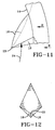
- Fig. 11 is a detailed representation of a tooth 17.
- the teeth 17 on the clamping surface 14, shown in Fig. 9, comprise a flank 16 ascending in the tightening pulling direction, which can be concave (continuous line) or convex (dotted line).
- the flanks 16 of the teeth 17 provided on the clamping surface 14 provide a sliding surface over which, during the tightening of the belt webbing, the belt webbing part 6 directed in the belt slot 8 slides without impediment.
- the retensioning results in a very tautly tightened lap belt and in addition a shortening of the chest belt that is guided from the insertion tongue locked in the belt buckle to the belt guide or anchoring point anchored to the top end of the B-pillar. Due to the very tautly tightened lap belt, knee injuries in particular, caused by the forward displacement of the vehicle occupant, are avoided. This can render an additional knee airbag superfluous in the vehicle.
- the fastening device can be designed such that after the tightening of the seat belt, it blocks a web extraction movement, which occurs against the tightening pulling direction, in the region of the belt slot.
- the teeth 17 comprise engaging flanks 18, extending against the belt web extraction direction and arranged at an approximate right angle to one another, as shown in Figs. 11 and 12.
- the arrangement of the teeth 17 on the clamping surface 14 corresponds to the oblique or diagonal course of the fabric structure of the belt webbing part 6 guided through the belt slot 8, as shown in Fig. 10. In Figs. 9 and 10, this oblique course or the thereto adapted oblique arrangement of the teeth 17 on the clamping surface 14 is shown.
- the direction of the engaging flanks 18 and the height and dimensions of the engaging flanks 18 correspond to the fabric structure of the seat belt webbing so that the engaging flanks are in engagement on the belt webbing fabric surfaces 24, 26 which run at an essentially right angle to one another, as shown in Fig. 10.
- Both engagement flanks 18 run obliquely to the clamping surface 14, so that they exercise a hook effect on the web in the web extraction direction, that is to say against the tightening pulling direction.
- the engagement surfaces 18 converge with the sliding flank 16, whereby said tip is extending against the belt web extraction direction. A hook locking is thus achieved, when the belt webbing moves in the web extraction direction, as indicated by the arrow 24 in Fig. 11.
- the quasi-surface engagement which is achieved through the multitude of engagement flanks 18, prevents the seat belt webbing from being held or blocked in the belt slot in the web extraction direction in an undamaged manner.
- the belt webbing guide 7 acts like an end fitting of the seat belt securely fastened to the vehicle structure or the seat substructure 4.
- the pretension of the spring 15 ensures that after the belt tightening, in one pulling motion, on the belt webbing part 6 and in the web extraction direction, that is against the arrows shown in Fig. 7, the teeth 17 on the clamping surface 14 automatically engage the fabric structure of the belt webbing part guided diagonally through the belt slot 8, as shown in Fig. 10. This ensures that during normal operation the belt webbing of the seat belt is held in a first position.
- the belt slot 8 is furthermore essentially reduced to the thickness of the seat belt by the clamping jaw 12 to protect against misuse.
- the fastening device 9 is a fastening lip 19.
- Fig. 13 the positioning of the fastening lip 19 during normal driving operation is shown. Due to the fastening lip the zero positioning of the seat belt is determined during normal driving operation. To this effect the belt webbing part 6 supported on the guiding surface 13 is pressed by the fastening lip 19. As shown in Fig. 14, during the tightening of the seat belt, the fastening lip, which displays a certain elasticity, is moved along with the belt webbing part 6 moved over the guiding surface 13 and is pulled over to the other side of the belt slot 8.
- the fastening device which in the embodiment of Figs. 6 to 14 is formed by the clamping device 11 or the clamping jaw 12 and in the embodiment of Figs. 13 and 14 by the fastening lip 19, can be provided with lateral guide projections 20, 21, the height of which corresponds approximately to the thickness of the belt webbing.
- lateral guide projections 20, 21, the height of which corresponds approximately to the thickness of the belt webbing can be provided with lateral guide projections 20, 21, the height of which corresponds approximately to the thickness of the belt webbing.
- the invention has been described in the above embodiments in such a way that the belt webbing guide and the belt tightening drive are arranged on the vehicle front seat. It is also possible, however, to fasten the belt webbing guide 7 to the car body, for instance to the bottom part of the B-pillar or the door sill of the vehicle. The can also be fastened to an appropriate point, for instance on the door sill. In connection with the clamping device described in Figs. 5 to 12, the same effect is achieved as described above.
- the load acting upon the seat belt during the forward displacement of the seat belt-wearing vehicle occupant is essentially completely taken up by the belt webbing guide.
- the belt webbing guide thus acts like an end fitting.
- the belt tightening drive can then be fastened by a reduced load-carrying fastening, for instance of approximately 5kN, in the seat substructure or else to another seat part, e.g. the backrest. In addition it is no longer required to provide the belt tightening drive with a reverse movement lock.
Landscapes
- Engineering & Computer Science (AREA)
- Mechanical Engineering (AREA)
- Automotive Seat Belt Assembly (AREA)
Abstract
Description
- The present invention relates to a three-point seat belt system for a motor vehicle front seat.
- A typical three-point seat belt system has three anchoring points. These anchoring points typically comprise an end fitting with which an end of the belt webbing is fastened to the motor vehicle structure. A belt buckle receives a buckle tongue that is slides on the belt webbing. An upper anchoring point, at shoulder height or above the vehicle front seat, is located on the B-pillar, for instance in the form of a belt guide via which the belt webbing extendable across the chest of a seat occupant is guided to a seat belt retractor. With this type of three-point seat belt it is known to retract the belt buckle, which constitutes one of the three anchoring points, using a belt tightening drive to eliminate slack in the belt webbing and to restrain the vehicle occupant in the vehicle seat. The activation of the belt tightening drive occurs during a crash and is triggered by a sensor device. A three-point seat belt system having a belt buckle connected to a belt tightening drive is known, for example, from US 5 519 997.
- There is provided in accordance with the present invention a three-point seat belt system for a motor vehicle front seat comprising a belt tightening drive fastened to the front seat and engages an anchoring point of the seat belt fastened to the vehicle seat, wherein a drive element of the belt tightening drive is securely connected to a belt webbing part that is guided from the lap belt through a belt webbing guide fastened to a seat substructure.
-
- Fig. 1 shows a first embodiment of the invention with a linear belt tightening drive that extends substantially parallel to the upper seat slide.
- Fig. 2 shows a second embodiment wherein the linear belt tightening drive is arranged transversely to the direction of seat travel in the rear of the seat substructure.
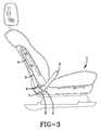
- Fig. 3 shows a third embodiment of the invention wherein the linear belt tightening drive is arranged laterally in the backrest.
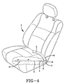
- Fig. 4 shows a fourth embodiment of the invention wherein the linear belt tightening drive is arranged diagonally in the seat substructure.
- Fig. 5 is a fragmentary view of a lap belt webbing part guided through the belt webbing guide secured to the seat substructure.
- Fig. 6 shows a clamping device that during normal operation holds the belt webbing in first position and after the tightening blocks the belt webbing in the web extraction direction.
- Fig. 7 shows the clamping device of Fig. 6 during the belt tightening process.
- Fig. 8 is a perspective view of the clamping device of Figs. 6 and 7.
- Fig. 9 is a perspective view of a clamping surface on a clamping jaw of the clamping device of Figs. 6 to 8.
- Fig. 10 is a top view of the arrangement of teeth on the clamping surface of the clamping jaw represented in Fig. 9.
- Fig. 11 is an enlarged view of a tooth on the clamping surface.
- Fig. 12 shows a tooth viewed in the direction of the arrows B in Fig. 11.
- Fig. 13 shows a further embodiment of the fastening device during normal operation.
- Fig. 14 shows the embodiment represented in Fig. 14 during the tightening of the seat belt.
-
- The embodiments for three-point seat belt systems shown in Figs. 1 to 4 are provided on a
front seat 1 of a motor vehicle. Part of alap belt 2 is shown. From thelap belt 2, abelt webbing part 6 is guided through abelt webbing guide 7 fastened to theseat substructure 4. Thebelt webbing guide 7 has abelt slot 8 through which thebelt webbing part 6 is guided. As shown in Fig. 5,thebelt webbing guide 7 has aflexible bar 10 with a curved guidingsurface 13, also shown in Figs. 6 to 8, around which around which thepart 6 of the belt webbing engaged by a belt tightening drive3 is directed. In Figs. 1 to 4, thebelt webbing part 6 extending from thelap belt 2 is, after being redirected by thebelt belt guide 7, extending towards a belt tightening drive3, which in the represented embodiments is a linear belt tightener. The linear belt tightening drive can in a conventional manner comprise a piston, with which a drive element, such as a traction cable, engaging the belt webbing, is connected. The piston is guided in a cylinder by a preferably pyrotechnic drive in an axial direction and thereby produces a tightening force that is transmitted to the belt webbing part that is guided through the belt webbing guide. - The
belt webbing part 6 is securely connected to adrive element 5, for instance a traction cable of the belt tightening drive3. The drive element is connected to a piston guided in a guide cylinder of the belt tightening drive3 and may be pyrotechnically driven. A belt tightening drive of this type is known for example, from US 5 519 997. In the embodiments represented in Figs. 1 to 4, thebelt webbing guide 7 is located in the region of the seat substructure where the seat surface and the back rest meet. The belt webbing guide is fastened to theseat substructure 4 in a stationary manner, so that the guidingsurface 13 assumes a predetermined orientation with regard to thebelt webbing part 6 guided to the belt tightening drive3. A redirecting line represented by dashed arrows in Fig. 5 coincident with a center line of the guidingsurface 13, represents a fixed predetermined angle with regard to the belt tightening direction. This redirecting line, or the guiding surface, is oriented such that the belt webbing is guided through thebelt slot 8 of the belt webbing guide. As shown in Fig. 5, this angle is approximately 45° with the apex of the angle being at about the guidingsurface 13. The lower, approximately horizontally guided web part in Fig. 5 is extending towards the belt tightening drive3, as indicated by the arrow pointing to the left in the drawing. The web part extending obliquely from above derives from thelap belt 2, as indicated by the arrow pointing obliquely downwards in the drawing. The orientation of the guidingsurface 13, as represented in Fig. 5, with regard to the web movement direction of the belt webbing guided to the belt tightening drive3 is dimensioned in such a way that thebelt webbing part 6 is guided essentially centrally through thebelt slot 8 of thebelt webbing guide 7 without any lateral displacement during the belt tightening process,. - In the embodiment shown in Fig. 1, the belt tightening direction is essentially parallel to the forward direction of travel of the vehicle, or parallel to the upper seat slide of the
seat substructure 4. The guide tube of thelinear belt tightener 3 extends essentially parallel thereto and is fastened to theseat substructure 4. In the embodiment represented in Fig. 2, the belt tightening drive3 is fastened to a rear side of theseat substructure 4 at essentially transverse to the direction of travel of the vehicle. The movement of thedrive element 5, for example a traction cable, and thus the tightening pulling direction, which is exercised on thebelt webbing part 6, also runs perpendicular to the longitudinal axis of the vehicle. In the embodiment shown in Fig. 3, the belt tightening drive3 is arranged substantially horizontally in the back rest of the motorvehicle front seat 1, so that the tightening pulling direction runs essentially parallel to the back rest of the vehicle seat. In the embodiment shown in Fig. 4, the belt tightening drive3 is fastened diagonally to the seat substructure, as seen in a top view. Accordingly, thedrive element 5 is a traction cable and the tightening pulling force exercised on the directedbelt webbing part 6 run in this direction. - The
belt webbing guide 7 is located on one side of the motorvehicle front seat 1, preferably in close proximity to the vehicle door sill. On the other side of the seat there is provided in a known manner a buckle, that is not shown, to which thelap belt 2 is guided. The belt buckle can be connected to the belt tightening drive in a known manner. It is not required, however, to connect the belt buckle with a tightening drive, since due to the belt tightening drive of the invention in combination with the belt webbing guide, tightening lengths of up to 200mm can be achieved. It is therefore not required to also tighten the belt buckle so that a required impact resistance of the belt buckle with regard to tightening and hence additional expenditure to the belt buckle can be omitted. The belt buckle can be a rigid restraint element or as an anchoring point of the three-point seat belt system that is rigidly connected to the vehicle seat or vehicle structure. The tightening effect produced by the belt tightening drive3 is transferred directly to thelap belt 2. The tightening length immediately affects thelap belt 2. This way, at an early stage of the crash, a secure restraint of the seat belt-wearing vehicle occupant in the motor vehicle front seat is achieved. - To maintain the tautly tightened lap belt after the tightening process, a
fastening device 9 is provided in the region of thebelt slot 8. The width of thebelt slot 8 can be reduced to the thickness of the belt webbing by afastening device 9 orclamping device 11, so that the belt guide is secured against misuse, for instance by children playing with the lap belt webbing. The fastening device is designed such that in the retensioning direction the pulling effect of by the belt tightening drive on the belt webbing can be transferred essentially without impediment. A movement in a direction opposite the retensioning direction is blocked by the fastening device, at least during normal operation. - Figs. 5 to 14 show embodiments of fastening devices. In the embodiment of Figs. 6 to 12, the
fastening device 9 is aclamping device 11. The clamping device comprises a clampingjaw 12 with a clampingsurface 14 having a curvature that is complementary to the curvature of the guidingsurface 13 on theflexible bar 10. The guidingsurface 13 and the clampingsurface 14 are substantially cylindrical surfaces running parallel to one another around a commonguiding surface axis 22. Fig. 10 is a top view of the arrangement of teeth on the clamping surface of the clamping jaw represented in Fig. 9, with the arrangement of the fabric structure of the belt webbing, which is guided through the webbing guide, with regard to the middle axis of the flexible bar, with an enlarged representation of a tooth as seen in a top view. The clampingsurface 14 is provided with locking teeth 17, the shape and arrangement of which is complementary to the fabric structure of the belt webbing, as shown in Fig. 10. As shown in Figs. 6 to 8, during the redirection thebelt webbing part 6 is guided between the clampingsurface 14 on the clampingjaw 12 and the guidingsurface 14 on theflexible bar 10. Between these two surfaces thebelt slot 8 is formed in thebelt webbing guide 7. The guidingsurface 13 and the clampingsurface 14 have curvatures complementary to one another and run parallel to one another. The clampingjaw 12 is pressed on the surface of the directedbelt webbing part 6 with spring pretension, provided by thespring 15. - Fig. 11 is a detailed representation of a tooth 17. The teeth 17 on the clamping
surface 14, shown in Fig. 9, comprise aflank 16 ascending in the tightening pulling direction, which can be concave (continuous line) or convex (dotted line). Theflanks 16 of the teeth 17 provided on the clampingsurface 14 provide a sliding surface over which, during the tightening of the belt webbing, thebelt webbing part 6 directed in thebelt slot 8 slides without impediment. When after the tightening process, due to the forward displacement of the seat belt-wearing vehicle occupant, a force is exercised on thebelt webbing part 6 guided through thebelt slot 8 against the tightening pulling direction in the belt web extraction direction, and thebelt webbing part 6 is marginally moved in this direction, an engagement of the teeth 17 in the fabric structure of thebelt webbing part 6 in the region of theentire belt slot 8 takes place. Due to the multitude of teeth engaging the fabric structure, the load acting upon the belt webbing is rather transferred like from a pressure surface to the belt webbing guide acting as an end fitting. During normal operation, the clamping jaw is forced on the belt webbing part guided through the belt slot with preferably spring pretensioning. The automatic tooth engagement for the blocking of the web extraction against the tightening pulling direction is further supported this way. - The retensioning results in a very tautly tightened lap belt and in addition a shortening of the chest belt that is guided from the insertion tongue locked in the belt buckle to the belt guide or anchoring point anchored to the top end of the B-pillar. Due to the very tautly tightened lap belt, knee injuries in particular, caused by the forward displacement of the vehicle occupant, are avoided. This can render an additional knee airbag superfluous in the vehicle.
- The fastening device can be designed such that after the tightening of the seat belt, it blocks a web extraction movement, which occurs against the tightening pulling direction, in the region of the belt slot. To this effect the teeth 17 comprise engaging
flanks 18, extending against the belt web extraction direction and arranged at an approximate right angle to one another, as shown in Figs. 11 and 12. The arrangement of the teeth 17 on the clampingsurface 14 corresponds to the oblique or diagonal course of the fabric structure of thebelt webbing part 6 guided through thebelt slot 8, as shown in Fig. 10. In Figs. 9 and 10, this oblique course or the thereto adapted oblique arrangement of the teeth 17 on the clampingsurface 14 is shown. The direction of theengaging flanks 18 and the height and dimensions of theengaging flanks 18 correspond to the fabric structure of the seat belt webbing so that the engaging flanks are in engagement on the belt webbing fabric surfaces 24, 26 which run at an essentially right angle to one another, as shown in Fig. 10. Both engagement flanks 18 run obliquely to the clampingsurface 14, so that they exercise a hook effect on the web in the web extraction direction, that is to say against the tightening pulling direction. At thetip 23, the engagement surfaces 18 converge with the slidingflank 16, whereby said tip is extending against the belt web extraction direction. A hook locking is thus achieved, when the belt webbing moves in the web extraction direction, as indicated by thearrow 24 in Fig. 11. The quasi-surface engagement, which is achieved through the multitude of engagement flanks 18, prevents the seat belt webbing from being held or blocked in the belt slot in the web extraction direction in an undamaged manner. Thebelt webbing guide 7 acts like an end fitting of the seat belt securely fastened to the vehicle structure or theseat substructure 4. - The pretension of the
spring 15 ensures that after the belt tightening, in one pulling motion, on thebelt webbing part 6 and in the web extraction direction, that is against the arrows shown in Fig. 7, the teeth 17 on the clampingsurface 14 automatically engage the fabric structure of the belt webbing part guided diagonally through thebelt slot 8, as shown in Fig. 10. This ensures that during normal operation the belt webbing of the seat belt is held in a first position. Thebelt slot 8 is furthermore essentially reduced to the thickness of the seat belt by the clampingjaw 12 to protect against misuse. - In the embodiment shown in Figs. 13 and 14, the
fastening device 9 is afastening lip 19. In Fig. 13 the positioning of thefastening lip 19 during normal driving operation is shown. Due to the fastening lip the zero positioning of the seat belt is determined during normal driving operation. To this effect thebelt webbing part 6 supported on the guidingsurface 13 is pressed by thefastening lip 19. As shown in Fig. 14, during the tightening of the seat belt, the fastening lip, which displays a certain elasticity, is moved along with thebelt webbing part 6 moved over the guidingsurface 13 and is pulled over to the other side of thebelt slot 8. - In Fig. 5, the fastening device, which in the embodiment of Figs. 6 to 14 is formed by the clamping
device 11 or the clampingjaw 12 and in the embodiment of Figs. 13 and 14 by thefastening lip 19, can be provided withlateral guide projections belt webbing part 6 are guided along these guide projections. This ensures that thebelt webbing part 6 guided through thebelt slot 8 retains its central position during the tightening process. - The invention has been described in the above embodiments in such a way that the belt webbing guide and the belt tightening drive are arranged on the vehicle front seat. It is also possible, however, to fasten the
belt webbing guide 7 to the car body, for instance to the bottom part of the B-pillar or the door sill of the vehicle. The can also be fastened to an appropriate point, for instance on the door sill. In connection with the clamping device described in Figs. 5 to 12, the same effect is achieved as described above. - In this case the load acting upon the seat belt during the forward displacement of the seat belt-wearing vehicle occupant is essentially completely taken up by the belt webbing guide. The belt webbing guide thus acts like an end fitting. The belt tightening drive can then be fastened by a reduced load-carrying fastening, for instance of approximately 5kN, in the seat substructure or else to another seat part, e.g. the backrest. In addition it is no longer required to provide the belt tightening drive with a reverse movement lock.
Claims (10)
- A three point seat belt system, in particular for a front seat of a motor vehicle, comprising a tightening drive anchored to the vehicle structure, characterised in that a drive element (5) of the tightening drive (3) is securely fastened to a belt webbing part (6) which derives from the lap belt and is guided through a webbing deflection point fastened to the vehicle structure.
- A three point seat belt system for a motor vehicle front seat (1) comprising a tightening drive (3) fastened to the front seat and which engages an anchoring point of the seat belt fastened to the vehicle seat, characterised in that a drive element (5) of the tightening drive (3) is securely connected to a belt webbing part (6), which is guided from the lap belt (2) through a webbing deflection point (7) fastened to the seat substructure (4).
- The three point seat belt system according to claim 1 or 2, characterised in that the tightening drive (3) is a linear tightener.
- The three point seat belt system according to one of claims 1 to 3, characterised in that the drive element (5) is securely connected to the end of the belt webbing part (6) guided through the webbing deflection point (7).
- The three point seat belt system according to one of claims 1 to 4, characterised in that the webbing deflection point (7) is secured to the side of the seat substructure (4), which lies opposite the seat side on which the belt buckle is fastened.
- The three point seat belt system according to one of claims 1 to 5, characterised in that the webbing deflection point (7) is fastened in the region of the seat substructure (4), in which the back rest and the seat surface meet.
- The three point seat belt system according to one of claims 1 to 6, characterised in that the flexing surface (13), around which the belt webbing part (6) guided through the webbing deflection point (7) is guided, assumes, with regard to the tightening pulling direction, a firmly predetermined angle, at which the belt webbing is guided essentially centrally through a belt slot (8) of the webbing deflection point (7).
- The three point seat belt system according to one of claims 1 to 7, characterised in that the webbing deflection point (7) comprises a fastening device (9), by which the belt webbing part (6) guided through the belt slot (8) is fastened in position zero during normal operation in the web length direction.
- The three point seat belt system according to claim 8, characterised in that the belt webbing part (6) is pressed by the fastening device (9) on a flexing bar (10) delimiting the belt slot (8).
- The three point seat belt system according to one of claims 1 to 10, characterised in that at the webbing deflection point (7), a clamping device (11) is provided which, during a web movement and against the tightening pulling direction, clamps the belt webbing part (6) guided through the webbing deflection point (7).
Applications Claiming Priority (2)
| Application Number | Priority Date | Filing Date | Title |
|---|---|---|---|
| DE10112853 | 2001-03-16 | ||
| DE10112853A DE10112853A1 (en) | 2001-03-16 | 2001-03-16 | Three-point seat belt system for a motor vehicle front seat |
Publications (2)
| Publication Number | Publication Date |
|---|---|
| EP1241060A1 true EP1241060A1 (en) | 2002-09-18 |
| EP1241060B1 EP1241060B1 (en) | 2003-12-17 |
Family
ID=7677804
Family Applications (1)
| Application Number | Title | Priority Date | Filing Date |
|---|---|---|---|
| EP02002450A Revoked EP1241060B1 (en) | 2001-03-16 | 2002-02-01 | Three-point seat belt system |
Country Status (3)
| Country | Link |
|---|---|
| US (1) | US6565121B2 (en) |
| EP (1) | EP1241060B1 (en) |
| DE (2) | DE10112853A1 (en) |
Cited By (2)
| Publication number | Priority date | Publication date | Assignee | Title |
|---|---|---|---|---|
| CN102485551A (en) * | 2010-12-03 | 2012-06-06 | 现代自动车株式会社 | Apparatus for mounting seat belt to vehicle body |
| IT201800002545A1 (en) * | 2018-02-09 | 2019-08-09 | Federico Bizzarri | REFERENCE DEVICE FOR SEAT BELTS |
Families Citing this family (22)
| Publication number | Priority date | Publication date | Assignee | Title |
|---|---|---|---|---|
| US6942251B2 (en) * | 2001-06-18 | 2005-09-13 | Trw Occupant Restraint Systems Gmbh & Co. Kg | Actuating device for a safety means |
| DE20200741U1 (en) * | 2002-01-18 | 2002-05-29 | Trw Repa Gmbh | The vehicle occupant restraint system |
| JP2003237533A (en) * | 2002-02-21 | 2003-08-27 | Araco Corp | Vehicle seat |
| JP2005239055A (en) * | 2004-02-27 | 2005-09-08 | Takata Corp | Occupant crash protection device |
| EP1593559B1 (en) * | 2004-05-04 | 2010-08-04 | Ford Global Technologies, LLC | Seat belt restraint system |
| US7350734B2 (en) * | 2005-10-13 | 2008-04-01 | Automotive Systems Laboratory, Inc. | Seat belt pretensioner |
| US7607508B2 (en) * | 2004-11-02 | 2009-10-27 | Ford Global Technologies Llc | Vehicle side collision occupant restraint system |
| JP5001529B2 (en) * | 2005-06-10 | 2012-08-15 | 富士フイルム株式会社 | Method for producing organic pigment fine particles |
| DE602005005191T2 (en) * | 2005-07-12 | 2009-03-19 | Key Safety Systems, Inc., Sterling Heights | pretensioners |
| JP5182843B2 (en) * | 2007-02-15 | 2013-04-17 | テイ・エス テック株式会社 | Vehicle seat |
| JP4981614B2 (en) * | 2007-10-15 | 2012-07-25 | タカタ株式会社 | Pretensioner and seat belt device |
| US7905514B2 (en) * | 2008-11-14 | 2011-03-15 | GM Global Technology Operations LLC | Motor vehicle safety restraint system |
| DE102008062262A1 (en) * | 2008-12-15 | 2010-06-17 | GM Global Technology Operations, Inc., Detroit | Knee restraint system for motor vehicle, particularly passenger vehicle, has absorber elements, which are fastened at pivot point and another pivot point at motor vehicle |
| US9840226B2 (en) * | 2012-06-13 | 2017-12-12 | The United States Of America As Represented By The Secretary Of The Army | Lighted egress apparatus |
| US9821759B2 (en) * | 2015-03-05 | 2017-11-21 | Ford Global Technologies, Llc | Seat-belt mounting system |
| US9821758B2 (en) * | 2016-02-05 | 2017-11-21 | Ford Global Technologies, Llc | Pretensioning, force-limiting seat belt assembly |
| DE102017209867A1 (en) * | 2017-06-12 | 2018-12-13 | Volkswagen Aktiengesellschaft | Retaining device for a vehicle |
| JP7091756B2 (en) * | 2018-03-22 | 2022-06-28 | マツダ株式会社 | Vehicle seat belt device |
| DE102019129993A1 (en) * | 2019-11-07 | 2021-05-12 | Zf Automotive Germany Gmbh | Seat belt system for a vehicle and vehicle with a seat belt system |
| JP7235413B2 (en) * | 2020-02-26 | 2023-03-08 | トヨタ自動車株式会社 | Vehicle seat device with wrap pretensioner |
| DE102022117991A1 (en) | 2022-07-19 | 2024-01-25 | Zf Automotive Germany Gmbh | End fitting belt tensioner |
| DE102022210677A1 (en) | 2022-10-10 | 2024-04-11 | Psa Automobiles Sa | Vehicle seating arrangement for a vehicle |
Citations (8)
| Publication number | Priority date | Publication date | Assignee | Title |
|---|---|---|---|---|
| US4008909A (en) * | 1973-02-26 | 1977-02-22 | Nissan Motor Co., Ltd. | Actuator for safety seat belt system |
| US4385775A (en) * | 1978-03-21 | 1983-05-31 | Nippon Soken, Inc. | Seat belt tensioning device for vehicle |
| US4682791A (en) * | 1984-02-25 | 1987-07-28 | Britax-Kolb Gmbh & Co. | Deflection device for a safety belt arrangement having progressive belt clamping |
| US4767161A (en) * | 1985-05-21 | 1988-08-30 | Autoflug Gmbh & Co. Fahrzeugtechnik | Safety belt arrangement |
| DE4415467C1 (en) * | 1994-05-03 | 1995-11-23 | Daimler Benz Ag | Safety belt device for motor vehicles |
| US5634664A (en) * | 1993-08-24 | 1997-06-03 | Honda Giken Kogyo Kabushiki Kaisha | Safety seat belt device |
| US5704638A (en) * | 1995-12-18 | 1998-01-06 | Alliedsignal Inc. | Integrated side impact inflator and module with seat belt pretensioning capability |
| US5845939A (en) * | 1996-04-16 | 1998-12-08 | Trw Occupant Restraint Systems Gmbh | Belt tensioner |
Family Cites Families (17)
| Publication number | Priority date | Publication date | Assignee | Title |
|---|---|---|---|---|
| FR2167270A5 (en) * | 1972-01-11 | 1973-08-24 | Ferodo Sa | |
| DE2249786A1 (en) * | 1972-10-11 | 1974-04-25 | Bayern Chemie Gmbh Flugchemie | SAFETY DEVICE FOR THE OCCUPANTS OF VEHICLES, IN PARTICULAR OF MOTOR VEHICLES |
| SE381814B (en) * | 1974-10-03 | 1975-12-22 | Foerenade Fabriksverken | DEVICE FOR STRETCHING A BAND INCLUDING IN A VEHICLE |
| DE3518121A1 (en) * | 1985-05-21 | 1986-11-27 | Autoflug GmbH & Co Fahrzeugtechnik, 2084 Rellingen | Tightening device for safety belts |
| US5219207A (en) * | 1992-01-22 | 1993-06-15 | Indiana Mills & Manufacturing, Inc. | Automatic locking tether for vehicle seat |
| DE4332206C2 (en) * | 1993-09-22 | 1997-08-14 | Hs Tech & Design | Drive device |
| JPH0726264U (en) * | 1993-10-26 | 1995-05-16 | 日本精工株式会社 | Retractor |
| GB2287869B (en) * | 1994-03-22 | 1997-10-22 | Autoliv Dev | Improvements in or relating to a safety-belt arrangement |
| US5492368A (en) * | 1995-02-23 | 1996-02-20 | General Motors Corporation | Rollover seat system |
| FR2758503B1 (en) * | 1997-01-23 | 1999-03-26 | Faure Bertrand Equipements Sa | MOTOR VEHICLE SEAT INCLUDING A SEAT BELT PRETENSIONER |
| DE29702125U1 (en) * | 1997-02-07 | 1997-06-05 | Trw Repa Gmbh | Vehicle occupant restraint system |
| DE19816277C1 (en) * | 1998-04-11 | 1999-11-25 | Audi Ag | Seat belt assembly for motor vehicles |
| US6238003B1 (en) * | 1998-10-13 | 2001-05-29 | Breed Automotive Technology, Inc. | Outboard sill pretensioner |
| DE29821272U1 (en) * | 1998-11-27 | 1999-03-25 | Trw Repa Gmbh | Belt system for restraining a vehicle occupant |
| DE19915275A1 (en) * | 1999-04-03 | 2000-10-05 | Volkswagen Ag | Safety belt arrangement for motor vehicle seats has threaded bolt on one belt for intentional release of connection between automatic belt tensioner/roller units |
| DE19960848B4 (en) * | 1999-12-16 | 2005-07-07 | Key Safety Systems, Inc., Sterling Heights | Device for tightening a safety belt |
| DE29922854U1 (en) * | 1999-12-27 | 2000-05-11 | Trw Repa Gmbh | Belt system for vehicles |
-
2001
- 2001-03-16 DE DE10112853A patent/DE10112853A1/en not_active Withdrawn
- 2001-10-08 US US09/972,609 patent/US6565121B2/en not_active Expired - Lifetime
-
2002
- 2002-02-01 DE DE60200129T patent/DE60200129T2/en not_active Revoked
- 2002-02-01 EP EP02002450A patent/EP1241060B1/en not_active Revoked
Patent Citations (8)
| Publication number | Priority date | Publication date | Assignee | Title |
|---|---|---|---|---|
| US4008909A (en) * | 1973-02-26 | 1977-02-22 | Nissan Motor Co., Ltd. | Actuator for safety seat belt system |
| US4385775A (en) * | 1978-03-21 | 1983-05-31 | Nippon Soken, Inc. | Seat belt tensioning device for vehicle |
| US4682791A (en) * | 1984-02-25 | 1987-07-28 | Britax-Kolb Gmbh & Co. | Deflection device for a safety belt arrangement having progressive belt clamping |
| US4767161A (en) * | 1985-05-21 | 1988-08-30 | Autoflug Gmbh & Co. Fahrzeugtechnik | Safety belt arrangement |
| US5634664A (en) * | 1993-08-24 | 1997-06-03 | Honda Giken Kogyo Kabushiki Kaisha | Safety seat belt device |
| DE4415467C1 (en) * | 1994-05-03 | 1995-11-23 | Daimler Benz Ag | Safety belt device for motor vehicles |
| US5704638A (en) * | 1995-12-18 | 1998-01-06 | Alliedsignal Inc. | Integrated side impact inflator and module with seat belt pretensioning capability |
| US5845939A (en) * | 1996-04-16 | 1998-12-08 | Trw Occupant Restraint Systems Gmbh | Belt tensioner |
Cited By (4)
| Publication number | Priority date | Publication date | Assignee | Title |
|---|---|---|---|---|
| CN102485551A (en) * | 2010-12-03 | 2012-06-06 | 现代自动车株式会社 | Apparatus for mounting seat belt to vehicle body |
| CN102485551B (en) * | 2010-12-03 | 2016-12-21 | 现代自动车株式会社 | For seat harness is installed the device to carbody |
| IT201800002545A1 (en) * | 2018-02-09 | 2019-08-09 | Federico Bizzarri | REFERENCE DEVICE FOR SEAT BELTS |
| WO2019155417A1 (en) * | 2018-02-09 | 2019-08-15 | Bizzarri Federico | Guiding device for safety belts |
Also Published As
| Publication number | Publication date |
|---|---|
| DE60200129D1 (en) | 2004-01-29 |
| EP1241060B1 (en) | 2003-12-17 |
| US20020130506A1 (en) | 2002-09-19 |
| DE60200129T2 (en) | 2004-09-16 |
| DE10112853A1 (en) | 2002-10-02 |
| US6565121B2 (en) | 2003-05-20 |
Similar Documents
| Publication | Publication Date | Title |
|---|---|---|
| US6565121B2 (en) | Three-point seat belt system | |
| KR100925574B1 (en) | Seat belt pretensioner | |
| US7118133B2 (en) | Seat belt pretensioner | |
| US7137650B2 (en) | Seat belt pretensioner | |
| US7147251B2 (en) | Seat belt pretensioner | |
| US20060163923A1 (en) | Child seat | |
| US6053532A (en) | Multi-point pretensioner system | |
| WO2002062632A1 (en) | Device for tightening a rear seat belt | |
| US5845939A (en) | Belt tensioner | |
| WO2000021796A1 (en) | Seat belt pretensioner | |
| KR101167336B1 (en) | Tightening device for a safety belt | |
| US11673529B2 (en) | Vehicle seat comprising a safety device | |
| US6382674B1 (en) | Apparatus for tensioning a seatbelt | |
| US7367630B2 (en) | Integrated seat of an automotive vehicle | |
| CA2574891C (en) | Seat belt pretensioner | |
| US6688646B2 (en) | Seat belt system with a belt tensioner | |
| KR100839293B1 (en) | Seat belt pretensioner | |
| JP6916048B2 (en) | Seat belt device | |
| KR100401729B1 (en) | Seat-belt tongue for vehicle | |
| MX2007000069A (en) | Seat belt pretensioner. |
Legal Events
| Date | Code | Title | Description |
|---|---|---|---|
| PUAI | Public reference made under article 153(3) epc to a published international application that has entered the european phase |
Free format text: ORIGINAL CODE: 0009012 |
|
| AK | Designated contracting states |
Kind code of ref document: A1 Designated state(s): AT BE CH CY DE DK ES FI FR GB GR IE IT LI LU MC NL PT SE TR |
|
| AX | Request for extension of the european patent |
Free format text: AL;LT;LV;MK;RO;SI |
|
| 17P | Request for examination filed |
Effective date: 20020903 |
|
| 17Q | First examination report despatched |
Effective date: 20021211 |
|
| AKX | Designation fees paid |
Designated state(s): DE FR GB IT |
|
| GRAH | Despatch of communication of intention to grant a patent |
Free format text: ORIGINAL CODE: EPIDOS IGRA |
|
| GRAS | Grant fee paid |
Free format text: ORIGINAL CODE: EPIDOSNIGR3 |
|
| GRAA | (expected) grant |
Free format text: ORIGINAL CODE: 0009210 |
|
| AK | Designated contracting states |
Kind code of ref document: B1 Designated state(s): DE FR GB IT |
|
| REG | Reference to a national code |
Ref country code: GB Ref legal event code: FG4D |
|
| REG | Reference to a national code |
Ref country code: IE Ref legal event code: FG4D |
|
| REF | Corresponds to: |
Ref document number: 60200129 Country of ref document: DE Date of ref document: 20040129 Kind code of ref document: P |
|
| ET | Fr: translation filed | ||
| PLBQ | Unpublished change to opponent data |
Free format text: ORIGINAL CODE: EPIDOS OPPO |
|
| PLBI | Opposition filed |
Free format text: ORIGINAL CODE: 0009260 |
|
| PLAX | Notice of opposition and request to file observation + time limit sent |
Free format text: ORIGINAL CODE: EPIDOSNOBS2 |
|
| 26 | Opposition filed |
Opponent name: AUTOLIV DEVELOPEMENT AB Effective date: 20040916 |
|
| REG | Reference to a national code |
Ref country code: IE Ref legal event code: MM4A |
|
| PLBB | Reply of patent proprietor to notice(s) of opposition received |
Free format text: ORIGINAL CODE: EPIDOSNOBS3 |
|
| RDAF | Communication despatched that patent is revoked |
Free format text: ORIGINAL CODE: EPIDOSNREV1 |
|
| APBP | Date of receipt of notice of appeal recorded |
Free format text: ORIGINAL CODE: EPIDOSNNOA2O |
|
| APAH | Appeal reference modified |
Free format text: ORIGINAL CODE: EPIDOSCREFNO |
|
| REG | Reference to a national code |
Ref country code: GB Ref legal event code: 732E |
|
| APBQ | Date of receipt of statement of grounds of appeal recorded |
Free format text: ORIGINAL CODE: EPIDOSNNOA3O |
|
| REG | Reference to a national code |
Ref country code: FR Ref legal event code: TP |
|
| PGFP | Annual fee paid to national office [announced via postgrant information from national office to epo] |
Ref country code: DE Payment date: 20070228 Year of fee payment: 6 |
|
| APBU | Appeal procedure closed |
Free format text: ORIGINAL CODE: EPIDOSNNOA9O |
|
| RDAG | Patent revoked |
Free format text: ORIGINAL CODE: 0009271 |
|
| STAA | Information on the status of an ep patent application or granted ep patent |
Free format text: STATUS: PATENT REVOKED |
|
| 27W | Patent revoked |
Effective date: 20071129 |
|
| GBPR | Gb: patent revoked under art. 102 of the ep convention designating the uk as contracting state |
Effective date: 20071129 Free format text: 20071129 |
|
| PGFP | Annual fee paid to national office [announced via postgrant information from national office to epo] |
Ref country code: FR Payment date: 20070201 Year of fee payment: 6 |
|
| PGFP | Annual fee paid to national office [announced via postgrant information from national office to epo] |
Ref country code: GB Payment date: 20080108 Year of fee payment: 7 Ref country code: IT Payment date: 20080225 Year of fee payment: 7 |
|
| PLAB | Opposition data, opponent's data or that of the opponent's representative modified |
Free format text: ORIGINAL CODE: 0009299OPPO |