EP1237723B1 - Digital offset printing registration - Google Patents
Digital offset printing registration Download PDFInfo
- Publication number
- EP1237723B1 EP1237723B1 EP00968193A EP00968193A EP1237723B1 EP 1237723 B1 EP1237723 B1 EP 1237723B1 EP 00968193 A EP00968193 A EP 00968193A EP 00968193 A EP00968193 A EP 00968193A EP 1237723 B1 EP1237723 B1 EP 1237723B1
- Authority
- EP
- European Patent Office
- Prior art keywords
- errors
- image
- data
- printing
- imaging
- Prior art date
- Legal status (The legal status is an assumption and is not a legal conclusion. Google has not performed a legal analysis and makes no representation as to the accuracy of the status listed.)
- Expired - Lifetime
Links
- 238000007645 offset printing Methods 0.000 title description 6
- 238000007639 printing Methods 0.000 claims abstract description 37
- 238000000034 method Methods 0.000 claims abstract description 35
- 238000003384 imaging method Methods 0.000 claims abstract description 32
- 238000000926 separation method Methods 0.000 claims abstract description 28
- 230000001419 dependent effect Effects 0.000 claims description 9
- 238000004891 communication Methods 0.000 claims description 3
- 230000008030 elimination Effects 0.000 claims description 3
- 238000003379 elimination reaction Methods 0.000 claims description 3
- 230000008569 process Effects 0.000 abstract description 21
- 238000002360 preparation method Methods 0.000 abstract description 3
- 238000012937 correction Methods 0.000 description 13
- 239000000758 substrate Substances 0.000 description 7
- 238000010586 diagram Methods 0.000 description 5
- 238000009792 diffusion process Methods 0.000 description 4
- 238000012986 modification Methods 0.000 description 4
- 230000004048 modification Effects 0.000 description 4
- 230000008859 change Effects 0.000 description 3
- 238000001514 detection method Methods 0.000 description 3
- 230000006870 function Effects 0.000 description 3
- 239000011159 matrix material Substances 0.000 description 3
- 238000013461 design Methods 0.000 description 2
- 230000000694 effects Effects 0.000 description 2
- 230000003993 interaction Effects 0.000 description 2
- 238000001459 lithography Methods 0.000 description 2
- 230000007246 mechanism Effects 0.000 description 2
- 230000004044 response Effects 0.000 description 2
- 230000000996 additive effect Effects 0.000 description 1
- 239000003795 chemical substances by application Substances 0.000 description 1
- 239000003086 colorant Substances 0.000 description 1
- 238000007796 conventional method Methods 0.000 description 1
- 238000011161 development Methods 0.000 description 1
- 238000005516 engineering process Methods 0.000 description 1
- 238000011156 evaluation Methods 0.000 description 1
- 238000002474 experimental method Methods 0.000 description 1
- 238000013507 mapping Methods 0.000 description 1
- 230000003287 optical effect Effects 0.000 description 1
- 238000012545 processing Methods 0.000 description 1
- 230000001360 synchronised effect Effects 0.000 description 1
- 238000012546 transfer Methods 0.000 description 1
- 230000001131 transforming effect Effects 0.000 description 1
- 238000011144 upstream manufacturing Methods 0.000 description 1
- 238000009736 wetting Methods 0.000 description 1
Images


Classifications
-
- G—PHYSICS
- G06—COMPUTING; CALCULATING OR COUNTING
- G06T—IMAGE DATA PROCESSING OR GENERATION, IN GENERAL
- G06T3/00—Geometric image transformations in the plane of the image
-
- B—PERFORMING OPERATIONS; TRANSPORTING
- B41—PRINTING; LINING MACHINES; TYPEWRITERS; STAMPS
- B41P—INDEXING SCHEME RELATING TO PRINTING, LINING MACHINES, TYPEWRITERS, AND TO STAMPS
- B41P2227/00—Mounting or handling printing plates; Forming printing surfaces in situ
- B41P2227/70—Forming the printing surface directly on the form cylinder
Definitions
- the present invention is directed to lithography, and in particular, to compensating for deformities in color separations by imaging correspondingly deformed images on printing plates, such that these plates will print the color separations in register.
- Color images are obtained by separating the image into four color process plates, these four colors corresponding to Cyan, Magenta, Yellow and Black, commonly known as "CMYK", that are then combined on paper. If an image is to be accurately represented, all four color separations must have the same length, scale and position when impressed on the paper. However, this is difficult, as there may be misalignment and scale errors, these errors being classified as either fixed errors or paper errors.
- Errors of the printing press mechanisms typically include plate cylinders having lost their roundness from wear or the like, and loosening of gears, bearings, etc., typically from wear over time.
- Paper errors typically result from paper wetting by fountain solution and ink, and by forces applied on the paper by the printing press, that tend to deform the paper. With the paper deformed, data is printed at undesired or unintended locations. Even when the deformation forces on the paper are released, the paper does not usually recover to its original configuration, and thus, there is a difference between the data (on the imaged printing plate) and the resultant printed image.
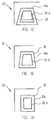
- FIG. 1A shows the desired or ideal situation where a rectangular image 20, formed of lines 20a and 20b, is to be imposed on the substrate 22, typically paper.
- a first separation here a black (K of the CMYK) impression 24.
- This impression 24 is trapezoidal in shape (formed of lines 24a, 24b) as a result of the paper deformation in the press.
- a second separation for example a Cyan or "C” separation is impressed onto this deformed paper 22, as represented by broken line 26, in a mis-registration.
- the subsequent Yellow “Y” and Magenta”M” separations will also be mis-registered in accordance with the paper deformation.
- a few presses have been designed such that printing plates are imaged on the press, or "on-press", whereby the plates are not removed from the press . for imaging.
- One exemplary press is the Model 74 KARAT offset digital press, manufactured by a Karat Digital Press of Herzlia, Israel in a joint venture with KBA (Koenig & Bauer Aktiengesellschaft). This design, besides reducing the make ready or preparation time, allows elimination of most of the registration fixed errors.
- US-A-5365847 discloses a control system for a printing press including a device for determining a reference printing image for the outer surface of a printing cylinder, and a device for modifying the reference printing image.
- a device for forming the modified printing image including means for determining a misregistration of said cylinder relative to another cylinder and means responsive to misregistration determining means for modifying the reference printing image to the subsequent printing image.
- EP-A-0770480 discloses a digital printing press system including a plurality of imaging units, a raster image processor, an error detection device, and an image data modification circuit.
- the image modification circuit is connected upstream of the raster image processor and communicates with the error detection device to modify the image data on the basis of register error signals from the area detection device.
- the present invention provides a system for elimination of printing registration errors as set out in claim 1.
- the present invention also provides a method of eliminating printing registration errors as set out in claim 5 below.
- the present invention improves the process of on-press printing member, typically printing plate, imaging, as it provides an automatic process for plate preparation that compensates for registration and print-length errors (plate loading is performed before imaging and therefore the position accuracy is determined by the imaging system).
- the system of the present invention creates deformed images on the printing members, typically plates, during the imaging stage, these deformed images, being such that the separations will be in register (coordinated) after printing.
- the present invention automatically determines the exact position for each data pixel within the distorted image to be placed onto the plates. This position is a sum of fixed errors and errors associated with stretch of the substrate, typically paper.
- the invention also provides an automatic procedure for predicting paper stretch errors.
- the correction process uses the image as a measure of the distribution of the ink load and a set of fixed parameters (determined by the paper, ink and other press conditions) to solve a differential equation that calculates the errors associated with the paper stretch. These errors are added to the fixed-errors map to obtain the final errors.
- the final pixel-location map is deduced by inverting the process, namely finding the position of a pixel such as when the position error is added to the position set, the requested position on print will be obtained.
- the resulting map is implemented, in conjunction with a"strobe" timing card and/or data manipulation card, to create the distorted plate image, resulting in a printing plate being imaged such that misregistration of the separations forming the printed image on the substrate are minimized or eliminated altogether.
- the present invention is operable with printing presses, typically digital offset printing presses.
- printing presses typically digital offset printing presses.
- one such digital printing press that uses printing plates is commercially available as the Quickmaster DI, from Heidelberg Druckmaschinen AG of Germany.
- the present invention utilizes digital offset printing deformation that is performed during the stage of imaging the printing plates and/or cylinders.
- the present invention utilizes a microprocessor or other computing device, as detailed above, to automatically obtain relevant information as to the amount of paper distortion induced by the ink-load distribution in the image to be printed, and then employs a strobe/ data manipulation system, such as detailed below.
- the system 40 includes an imaging drum 42, rotated via a shaft (not shown) by a motor 44, that is controlled by drum motor control 48.
- An encoder 46 is coupled to the drum shaft, for supplying digital data to the carriage control system 60, to the drum motor control 48 and to the strobe card 72.
- An Imaging carriage 50 controlled by the carriage control system 60, is formed of a laser control card 52, and an optical head 54 which produces a high intensity laser beam 56 directed onto the imaging drum 42.
- Carriage control system 60 is used to move the imaging carriage 50 along the drum 42.
- the carriage system 60 comprise a carriage motor control 62, carriage motor 64 and typically a ball screw 66, which translates the rotational movement of motor 64 into translational movement along the drum 42.
- Strobe card 72 locks on the frequency of the encoder signal 46, and generates a high frequency expose clock 74, that is in phase with the rotation of the drum 42.
- the ratio between the high frequency signal and the encoder signal 46 is kept constant.
- the strobe card 72 is such that it can be preloaded with data from correction table 70.
- Data in the correction table 70 (typically in a data manipulation card) is such that minor modifications of the ratio between the high frequency signal and the encoder signal are made easily.
- the data can be expanded by slowing down the expose clock 74, or compressed by raising the expose clock 74.
- the data correction table are such that they can change the rate of imaging, while the speed of the imaging drum 42 and the speed of the carriage 50 are synchronized and kept constant.
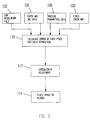
- Fig. 3 shows a flow diagram of the automatic correction scheme of the present invention.
- the image itself is typically in the form of a low resolution file, at block 102.
- the low-resolution file, block 102 typically has a resolution of 1 dot per millimeter, and as such, is accurate enough for error evaluation.
- the low-resolution file may employ resolutions as great as 10 dots per millimeter.
- a low-resolution file is prepared by InkProTM, available from Scitex Corporation of Herzelia, Israel. Turning now to the process 110, it is designed to calculate the error of each pixel, at the low resolution image, for each separation (typically separations 1-4, corresponding to CMYK, respectively), with respect to a first reference separation.
- u i (x,y) is defined as the misregister in the x-direction of the separation i at a point (x,y) on the paper.
- x is the drum perimeter axis
- y is the carriage screw axis. Only the x-component of the misregister is of interest here, since it is usually much larger than that along the y direction.
- the magnitude of u i (x,y) depends on (x,y) and i . This dependence is determined by the ink load on paper f j (x,y) of previous separations j ⁇ i .
- the ink load plays the role of an error source in the equation describing the magnitude of the misregister.
- each separation error is affected by the previously printed separations, according to the principle outlined above. Therefore:
- the error in separation 4 equals the sum of errors in separations 1 to 3.
- the ink load functions f j (x,y) are derived from the CMYK file values by transforming it thorough a 1-D LUT that takes into account the dot gain and a correction for the non-linear response of the misregister on the ink coverage on paper.
- u (u K , u C , u M , u Y ) is the errors four-vector
- f ( f K , f C , f M , f Y ) is the image four-separation data (taking into account the 1-D-LUT correction).
- Aij is the matrix, discussed above, describing the relation between the registration errors and the ink load
- D is the diffusion parameter
- the parameters Aij, Bij and D are dependent on paper, ink, and machine parameters. To determine them, a calibration process is done, and the values of the parameters are saved in a database for future use.
- the calibration process involves imaging and printing of "synthetic" files for a certain set of ink, paper and machine parameters.
- the parameters Aij, Bij and D are adjusted until the measured errors are identical (or within a small margin) to those predicted by the model.
- a careful design of the "synthetic" files allows for faster and easier calibration, by determining some of the parameters independently from the others. For example, the use of a full format, one separation uniform coverage simplifies the equation by removing the y-dependence, and the second-order interaction terms. Thus, it allows an easy determination of some of the Aij's. Repeating the process with another separation will give other Aij's until all of them are obtained. Then, the parameter D and the Bij can be determined by using more complex files.
- Fixed errors are mapped on the plate surface, by imaging and printing the same grid for all separations, and then measuring the relative shifts with respect to the first separation on each point of the grid, to produce the fixed-errors map.
- the fixed-errors map is saved in memory, prior to imaging.
- the user defines the printing variables before starting imaging the next job.
- the parameters, defined during the calibration stage are recalled from the database and loaded into the algorithm or program of the process.
- the low-resolution file is loaded into an array, and the differential equation is transformed into a difference scheme and solved numerically. The results give a good estimate of the paper stretch errors, associated with the ink load.
- an interpolated fixed error map is added to the image dependent errors to obtain the total error magnitude as a function of position.
- the interpolation is required because the typical resolution of the measured error map is about 0.1 dots per millimeter, while the image dependent errors are calculated on a 1 dot per millimeter grid.
- the strobe/data system is optimized, as the strobe "timing" card 72 and/or data manipulation card adjusts, expands or compresses (as detailed above) the resultant image by controlling the rate of imaging (typically by controlling the laser beam 56 as detailed above), at block 112 (Fig.3). In this way, the residual errors after correction are minimal.
- the image, now "distorted” by above detailed process is then placed onto printing members, typically plates, or other substrates, at block 114 (Fig. 3).
- the process is completely transparent to the user (and does not require operator intervention, except for the initial error mapping and paper/ink calibration setup). It does not require expensive mechanical apparatus, since the correction is distribution of done by a software/electronic hardware setting.
- the method is applicable to all printing technologies, since it connects the geometrical errors to the image printed.
- the technique is applicable to prepress imaging machines, provided the ink- paper calibration data is available.
- the methods disclosed herein may be implemented by software or software means (data) executable on computing means, such as a CPU, PC, or other similar data processors, microprocessor, embedded processors, microcomputers, microcontrollers, etc.
- the computing means processes the inputted data from apparatus in communication therewith to calculate a desired result. Processing includes performing operations, preferably in the form of programs or algorithms (as detailed above) for performing the detailed methods of the present invention.
Landscapes
- Physics & Mathematics (AREA)
- General Physics & Mathematics (AREA)
- Engineering & Computer Science (AREA)
- Theoretical Computer Science (AREA)
- Image Processing (AREA)
- Pens And Brushes (AREA)
- Mobile Radio Communication Systems (AREA)
- Inking, Control Or Cleaning Of Printing Machines (AREA)
- Control Of Position Or Direction (AREA)
- Manufacture Or Reproduction Of Printing Formes (AREA)
Abstract
Description
- This patent application claims priority from and is related to U.S. Provisional Patent Application S/
N 60/157,856, entitled: DIGITAL OFFSET PRINTING REGISTRATION, filed on October 6, 1999, this Provisional Patent Application incorporated by reference in its entirety herein. - The present invention is directed to lithography, and in particular, to compensating for deformities in color separations by imaging correspondingly deformed images on printing plates, such that these plates will print the color separations in register.
- Conventional lithography processes typically replicate images by transferring ink from a previously prepared plate onto a substrate, typically paper. In offset printing, this transfer is done indirectly by a soft blanket that is stamped by the plate. This soft blanket then impresses this image onto paper.
- Color images are obtained by separating the image into four color process plates, these four colors corresponding to Cyan, Magenta, Yellow and Black, commonly known as "CMYK", that are then combined on paper. If an image is to be accurately represented, all four color separations must have the same length, scale and position when impressed on the paper. However, this is difficult, as there may be misalignment and scale errors, these errors being classified as either fixed errors or paper errors.
- Fixed errors are errors in misalignment and scale that do not change from image to image. These errors are typically caused by tolerances of the prepress imaging devices, errors produced during development of the imaged plates, errors in mounting the plates on the printing press cylinders, and errors of the printing press mechanisms. Errors of the printing press mechanisms typically include plate cylinders having lost their roundness from wear or the like, and loosening of gears, bearings, etc., typically from wear over time.
- Paper errors typically result from paper wetting by fountain solution and ink, and by forces applied on the paper by the printing press, that tend to deform the paper. With the paper deformed, data is printed at undesired or unintended locations. Even when the deformation forces on the paper are released, the paper does not usually recover to its original configuration, and thus, there is a difference between the data (on the imaged printing plate) and the resultant printed image.
- Paper deformation effects, that result in paper errors, are explained by Figs. 1A-1C. Specifically, Fig. 1A shows the desired or ideal situation where a
rectangular image 20, formed of lines 20a and 20b, is to be imposed on thesubstrate 22, typically paper. In Fig. 1B, thepaper 22 has been impressed with a first separation, here a black (K of the CMYK)impression 24. Thisimpression 24 is trapezoidal in shape (formed of lines 24a, 24b) as a result of the paper deformation in the press. Subsequently, in Fig. 1C, a second separation, for example a Cyan or "C" separation is impressed onto thisdeformed paper 22, as represented bybroken line 26, in a mis-registration. Similarly in this manner, the subsequent Yellow "Y" and Magenta"M" separations will also be mis-registered in accordance with the paper deformation. - In conventional press systems, some of the mis-registration caused by the fixed errors was correctable mechanically by the operator after reviewing the initial printed sheets. In this case, the operator manually adjusted the relative positions of the printing plates or changed pressure on the printed substrate.
- These manual, operator-made adjustments have drawbacks. Initially, these adjustments are time consuming and require considerable operator skill.
- Additionally, the adjustments of plate cylinders required expensive mechanical devices. Even in conventional presses, although the time required for adjustment is lessened, the adjustment machinery is more complex and more expensive.
- A few presses have been designed such that printing plates are imaged on the press, or "on-press", whereby the plates are not removed from the press . for imaging. One exemplary press is the Model 74 KARAT offset digital press, manufactured by a Karat Digital Press of Herzlia, Israel in a joint venture with KBA (Koenig & Bauer Aktiengesellschaft). This design, besides reducing the make ready or preparation time, allows elimination of most of the registration fixed errors.
- US-A-5365847 discloses a control system for a printing press including a device for determining a reference printing image for the outer surface of a printing cylinder, and a device for modifying the reference printing image. A device for forming the modified printing image including means for determining a misregistration of said cylinder relative to another cylinder and means responsive to misregistration determining means for modifying the reference printing image to the subsequent printing image.
- EP-A-0770480 discloses a digital printing press system including a plurality of imaging units, a raster image processor, an error detection device, and an image data modification circuit. The image modification circuit is connected upstream of the raster image processor and communicates with the error detection device to modify the image data on the basis of register error signals from the area detection device.
- The present invention provides a system for elimination of printing registration errors as set out in claim 1. The present invention also provides a method of eliminating printing registration errors as set out in claim 5 below.
- The present invention improves the process of on-press printing member, typically printing plate, imaging, as it provides an automatic process for plate preparation that compensates for registration and print-length errors (plate loading is performed before imaging and therefore the position accuracy is determined by the imaging system). The system of the present invention creates deformed images on the printing members, typically plates, during the imaging stage, these deformed images, being such that the separations will be in register (coordinated) after printing.
- The present invention automatically determines the exact position for each data pixel within the distorted image to be placed onto the plates. This position is a sum of fixed errors and errors associated with stretch of the substrate, typically paper. The invention also provides an automatic procedure for predicting paper stretch errors.
- The correction process uses the image as a measure of the distribution of the ink load and a set of fixed parameters (determined by the paper, ink and other press conditions) to solve a differential equation that calculates the errors associated with the paper stretch. These errors are added to the fixed-errors map to obtain the final errors. The final pixel-location map is deduced by inverting the process, namely finding the position of a pixel such as when the position error is added to the position set, the requested position on print will be obtained. The resulting map is implemented, in conjunction with a"strobe" timing card and/or data manipulation card, to create the distorted plate image, resulting in a printing plate being imaged such that misregistration of the separations forming the printed image on the substrate are minimized or eliminated altogether.
- The present invention will be described with reference to the accompanying drawings, wherein like reference numerals or characters identify corresponding or like components. In the drawings:
- Figs. 1A-1C are diagrams useful in explaining problems associated with the prior art ;
- Fig. 2 is a schematic diagram of the imaging head and the strobe card and associated systems in accordance with an embodiment of the present invention;
- Fig. 3 is a flow chart detailing an embodiment of the present invention ;
- Fig. 4 is a diagram of a printed pattern where the ink load is uniform along the Y-axis;
- Fig. 5 is a plot of the registration error along the X-axis, in accordance with the printed pattern of Fig. 4 ;
- Fig. 6 is a diagram of a printed pattern where the ink load is uniform along the X-axis; and
- Fig. 7 is a plot of the registration error along the Y-axis, in accordance with the printed pattern of Fig. 6.
-
- The present invention is operable with printing presses, typically digital offset printing presses. For example, one such digital printing press, that uses printing plates is commercially available as the Quickmaster DI, from Heidelberg Druckmaschinen AG of Germany. The present invention utilizes digital offset printing deformation that is performed during the stage of imaging the printing plates and/or cylinders.
- The present invention utilizes a microprocessor or other computing device, as detailed above, to automatically obtain relevant information as to the amount of paper distortion induced by the ink-load distribution in the image to be printed, and then employs a strobe/ data manipulation system, such as detailed below.
- Turning to Fig. 2, there is shown an exemplary
imaging drum system 40. Thesystem 40 includes animaging drum 42, rotated via a shaft (not shown) by amotor 44, that is controlled bydrum motor control 48. Anencoder 46 is coupled to the drum shaft, for supplying digital data to thecarriage control system 60, to thedrum motor control 48 and to thestrobe card 72. AnImaging carriage 50, controlled by thecarriage control system 60, is formed of alaser control card 52, and anoptical head 54 which produces a highintensity laser beam 56 directed onto theimaging drum 42. -
Carriage control system 60 is used to move theimaging carriage 50 along thedrum 42. Thecarriage system 60 comprise acarriage motor control 62,carriage motor 64 and typically aball screw 66, which translates the rotational movement ofmotor 64 into translational movement along thedrum 42.Strobe card 72 locks on the frequency of theencoder signal 46, and generates a high frequency exposeclock 74, that is in phase with the rotation of thedrum 42. - In normal operation, the ratio between the high frequency signal and the
encoder signal 46 is kept constant. Also, thestrobe card 72 is such that it can be preloaded with data from correction table 70. Data in the correction table 70 (typically in a data manipulation card) is such that minor modifications of the ratio between the high frequency signal and the encoder signal are made easily. - As a result of this modification the data can be expanded by slowing down the
expose clock 74, or compressed by raising theexpose clock 74. By extending and compressing the data, corrections of the image plates is achieved in order to minimize and eliminate any misregistration of the color separations in a printed image. This is because thestrobe card 72 and data correction table are such that they can change the rate of imaging, while the speed of theimaging drum 42 and the speed of thecarriage 50 are synchronized and kept constant. - Fig. 3 shows a flow diagram of the automatic correction scheme of the present invention. Initially, the image itself is typically in the form of a low resolution file, at
block 102. Data as to the substrate and ink to be used, typically from a stored data base, is atblock 104, and press parameters, such as speed, impression pressure, ink temperatures are atblock 106. A fixed error map, atblock 108, and parameters for the process, block 110, form other elements for performing the present invention. - The low-resolution file, block 102, typically has a resolution of 1 dot per millimeter, and as such, is accurate enough for error evaluation. The low-resolution file may employ resolutions as great as 10 dots per millimeter.
- One example of a low-resolution file is prepared by InkPro™, available from Scitex Corporation of Herzelia, Israel. Turning now to the
process 110, it is designed to calculate the error of each pixel, at the low resolution image, for each separation (typically separations 1-4, corresponding to CMYK, respectively), with respect to a first reference separation. - The process is directed to the relation between the errors and the image, where, ui(x,y) is defined as the misregister in the x-direction of the separation i at a point (x,y) on the paper. Here x is the drum perimeter axis, y is the carriage screw axis. Only the x-component of the misregister is of interest here, since it is usually much larger than that along the y direction. The magnitude of ui(x,y) depends on (x,y) and i. This dependence is determined by the ink load on paper fj (x,y) of previous separations j ≤ i. The ink load plays the role of an error source in the equation describing the magnitude of the misregister. When calculating the ink load function, dot gain and the non-linear response of the paper on ink load must be taken into account by passing each image dot-area through a 1-D-LUT (look up table) correction.
- The process is based on experiments showing the following behavior. Initially, a pattern was printed, that was uniform along the Y-axis (Fig. 4). Points 120a, 121a, 122a and 123a designate borders of the ink area. Specifically, where the ink-load changes along the X-axis, the errors of the different separations were found to be proportional to the integral ink load, as plotted in Fig. 5, where points 120b, 121b, 122b and 123b designate the ink borders corresponding to the points of Fig. 4.
- When a pattern was printed that was uniform along the X-axis (Fig. 6), namely, where the ink-load changes along the Y-axis, the errors of the different separations were found to behave as plotted in Fig. 7.
- This behavior is similar to that of a heat equation with source gi (x,y), known in the art, which led to the assumption that the errors ui(x,y) follow a diffusion equation:
- Where D is the diffusion constant. It can be seen, that when the ink-load gi(x,y) does not change with y, namely gi(x,y) = gi(x), we obtain as a solution an integral (□2/□y2 drops out), thus: □u/□x = gi(x). Hence,

- When y dependence is inserted, a "heat diffusion" process occurs that causes an error in the inked side of the paper to "spill" over into the clear areas.
- When calculating the errors, each separation error is affected by the previously printed separations, according to the principle outlined above. Therefore:

- When solving the equations, a constant matrix is used to describe the additive effect, e.g., the error in separation 4 equals the sum of errors in separations 1 to 3. Note that the ink load functions fj (x,y) are derived from the CMYK file values by transforming it thorough a 1-D LUT that takes into account the dot gain and a correction for the non-linear response of the misregister on the ink coverage on paper.
- The final equation using a vector notation is:Here, u = (uK, uC, uM, uY) is the errors four-vector, and f = (f K, f C, f M, f Y) is the image four-separation data (taking into account the 1-D-LUT correction). Aij is the matrix, discussed above, describing the relation between the registration errors and the ink load, D is the diffusion parameter and Bij is a matrix describing second order corrections, taking into account interaction effects, related to ink-over-ink areas. In most cases, these corrections are small, and therefore Bij can typically be set Bij=0 for all i,j. The parameters Aij, Bij and D are dependent on paper, ink, and machine parameters. To determine them, a calibration process is done, and the values of the parameters are saved in a database for future use.

- The calibration process involves imaging and printing of "synthetic" files for a certain set of ink, paper and machine parameters. The parameters Aij, Bij and D are adjusted until the measured errors are identical (or within a small margin) to those predicted by the model.
- A careful design of the "synthetic" files allows for faster and easier calibration, by determining some of the parameters independently from the others. For example, the use of a full format, one separation uniform coverage simplifies the equation by removing the y-dependence, and the second-order interaction terms. Thus, it allows an easy determination of some of the Aij's. Repeating the process with another separation will give other Aij's until all of them are obtained. Then, the parameter D and the Bij can be determined by using more complex files.
- To obtain the fixed error map, the following procedure is applied. Fixed errors are mapped on the plate surface, by imaging and printing the same grid for all separations, and then measuring the relative shifts with respect to the first separation on each point of the grid, to produce the fixed-errors map. The fixed-errors map is saved in memory, prior to imaging.
- During operation, the user defines the printing variables before starting imaging the next job. The parameters, defined during the calibration stage, are recalled from the database and loaded into the algorithm or program of the process. The low-resolution file is loaded into an array, and the differential equation is transformed into a difference scheme and solved numerically. The results give a good estimate of the paper stretch errors, associated with the ink load.
- When calculating the final errors, an interpolated fixed error map is added to the image dependent errors to obtain the total error magnitude as a function of position. The interpolation is required because the typical resolution of the measured error map is about 0.1 dots per millimeter, while the image dependent errors are calculated on a 1 dot per millimeter grid. After the total number of errors is known, the strobe/data system is optimized, as the strobe "timing"
card 72 and/or data manipulation card adjusts, expands or compresses (as detailed above) the resultant image by controlling the rate of imaging (typically by controlling thelaser beam 56 as detailed above), at block 112 (Fig.3). In this way, the residual errors after correction are minimal. The image, now "distorted" by above detailed process, is then placed onto printing members, typically plates, or other substrates, at block 114 (Fig. 3). - The process is completely transparent to the user (and does not require operator intervention, except for the initial error mapping and paper/ink calibration setup). It does not require expensive mechanical apparatus, since the correction is distribution of done by a software/electronic hardware setting.
- Although the preferred embodiment of the present invention has been described in terms of digital offset printing, the method is applicable to all printing technologies, since it connects the geometrical errors to the image printed. In particular, the technique is applicable to prepress imaging machines, provided the ink- paper calibration data is available.
- The methods and apparatus disclosed herein have been described without reference to specific hardware of software. Rather, the methods and apparatus have been described in a manner sufficient to enable persons of ordinary skill in the art to readily adapt commercially available hardware and software as may be needed to reduce any of the embodiments of the present invention to practice without undue experimentation and using conventional techniques.
- It will further be appreciated by persons skilled in the art that the methods disclosed herein may be implemented by software or software means (data) executable on computing means, such as a CPU, PC, or other similar data processors, microprocessor, embedded processors, microcomputers, microcontrollers, etc. The computing means processes the inputted data from apparatus in communication therewith to calculate a desired result. Processing includes performing operations, preferably in the form of programs or algorithms (as detailed above) for performing the detailed methods of the present invention.
- While preferred embodiments of the present invention have been described, so as to enable one of skill in the art to practice the present invention, the preceding description is intended to be exemplary only. It should not be used to limit the scope of the invention, which should be determined by reference to the following claims.
Claims (8)
- A system for elimination of printing registration errors, comprising a processor for computing distortion parameters and an imaging system in communication with said processor and configured for exposing distorted images, characterised in that the processor is programmed for:receiving input data including paper data, at least one machine parameter (106) and ink distribution data (102), the processor calculating image dependent errors from said input data;receiving at least one fixed error map (108) dependent on machine parameters and obtained during a calibration run; andpredicting registration errors based on the fixed error map (108) and said image dependent errors; andcomputing distortion parameters based on said registration errors for creating distorted images.
- A system as claimed in claim 1, wherein said ink distribution data for an image file to be exposed is provided by a low resolution image file (102) derived from said image file.
- A system as claimed in claim 1 or 2, where said imaging system includes a strobe card (72) configured for changing timing signals.
- A system as claimed in claim 1 or 2, wherein said imaging system includes means for changing the resolution of an image.
- A method of eliminating printing registration errors in a system comprising a processor for computing distortion parameters and an imaging system in communication with said processor and configured for exposing distorted images, characterised by:receiving input data including paper data, at least one machine parameter (106) and ink distribution data (102),calculating image dependent errors from said input data;receiving at least one fixed error map (108) dependent on machine parameters and obtained during a calibration run; andpredicting registration errors based on the fixed error map (108) and said image dependent errors; andcomputing distortion parameters based on said registration errors for creating distorted images.
- A method as claimed in claim 5, wherein said step of computing includes providing a reference image (102), calculating errors for substantially all of the pixels for at least one colour separation in said reference image; and
utilizing at least one of strobe data or data manipulation card (72) in combination with said calculated errors to control the rate of imaging to create a distorted image. - A method as claimed in claim 6, wherein said step of providing a reference image includes providing said reference image in a low resolution file (102).
- A method as claimed in claim 5, 6 or 7, additionally comprising providing a printing member; and placing said distorted image onto said printing member.
Applications Claiming Priority (3)
| Application Number | Priority Date | Filing Date | Title |
|---|---|---|---|
| US15785699P | 1999-10-06 | 1999-10-06 | |
| US157856P | 1999-10-06 | ||
| PCT/IL2000/000620 WO2001025012A1 (en) | 1999-10-06 | 2000-10-04 | Digital offset printing registration |
Publications (2)
| Publication Number | Publication Date |
|---|---|
| EP1237723A1 EP1237723A1 (en) | 2002-09-11 |
| EP1237723B1 true EP1237723B1 (en) | 2004-04-14 |
Family
ID=22565563
Family Applications (1)
| Application Number | Title | Priority Date | Filing Date |
|---|---|---|---|
| EP00968193A Expired - Lifetime EP1237723B1 (en) | 1999-10-06 | 2000-10-04 | Digital offset printing registration |
Country Status (5)
| Country | Link |
|---|---|
| EP (1) | EP1237723B1 (en) |
| AT (1) | ATE264195T1 (en) |
| AU (1) | AU7814000A (en) |
| DE (1) | DE60009952T2 (en) |
| WO (1) | WO2001025012A1 (en) |
Families Citing this family (3)
| Publication number | Priority date | Publication date | Assignee | Title |
|---|---|---|---|---|
| JP4387634B2 (en) * | 2001-03-27 | 2009-12-16 | 株式会社小森コーポレーション | Control device for image printing device |
| US6997108B2 (en) | 2001-08-21 | 2006-02-14 | Mitsubishi Heavy Industries, Ltd. | Plate-making type printing press, multi-color printing press and plate-making type printing method |
| DE102016000335A1 (en) * | 2016-01-18 | 2017-07-20 | Heidelberger Druckmaschinen Ag | Method for compensating job and machine specific registration inaccuracies and register errors |
Family Cites Families (3)
| Publication number | Priority date | Publication date | Assignee | Title |
|---|---|---|---|---|
| US5365847A (en) * | 1993-09-22 | 1994-11-22 | Rockwell International Corporation | Control system for a printing press |
| US5715498A (en) * | 1994-09-16 | 1998-02-03 | Canon Kabushiki Kaisha | Color image forming apparatus and method for forming a color image corrected for aberration in registration of image stations for each color |
| EP0770480B1 (en) * | 1995-10-25 | 2001-12-19 | Heidelberger Druckmaschinen Aktiengesellschaft | Printing press with register control system |
-
2000
- 2000-10-04 WO PCT/IL2000/000620 patent/WO2001025012A1/en active IP Right Grant
- 2000-10-04 DE DE60009952T patent/DE60009952T2/en not_active Expired - Lifetime
- 2000-10-04 AT AT00968193T patent/ATE264195T1/en not_active IP Right Cessation
- 2000-10-04 AU AU78140/00A patent/AU7814000A/en not_active Abandoned
- 2000-10-04 EP EP00968193A patent/EP1237723B1/en not_active Expired - Lifetime
Also Published As
| Publication number | Publication date |
|---|---|
| WO2001025012A1 (en) | 2001-04-12 |
| DE60009952T2 (en) | 2004-09-02 |
| EP1237723A1 (en) | 2002-09-11 |
| ATE264195T1 (en) | 2004-04-15 |
| AU7814000A (en) | 2001-05-10 |
| DE60009952D1 (en) | 2004-05-19 |
Similar Documents
| Publication | Publication Date | Title |
|---|---|---|
| US5662044A (en) | Offset printing method | |
| US4546700A (en) | Method and apparatus for sensing and maintaining color registration | |
| EP0767059B1 (en) | Ink separation device for printing press ink feed control | |
| US6024504A (en) | Process for correcting geometric errors in the transfer of information to a printing stock | |
| US20040200369A1 (en) | Method and system for printing press image distortion compensation | |
| JPH054330A (en) | Ink control and method for preconditioning ink amount adjusting element for each zone | |
| EP0533411A2 (en) | Color printing yielding a dense black image | |
| US6253678B1 (en) | Method of printing to reduce misregistration | |
| JP2000318135A (en) | Method for controlling registering in duplicated printing of partial colors | |
| US6895862B1 (en) | Digital offset printing registration | |
| US20040012647A1 (en) | Printing apparatus with dot-gain compensation using spatial filter | |
| CA2353289C (en) | Method of correcting local, machine-based inking errors on rotary printing machines | |
| JP2888992B2 (en) | Process control strip and recording method | |
| EP1218184B1 (en) | Prediction and prevention of offset printing press problems | |
| EP1237723B1 (en) | Digital offset printing registration | |
| JP2003500940A (en) | Method and apparatus for compensating for dot gain in stochastic printing | |
| US7280259B2 (en) | Method for printing a color proof using a spatial filter | |
| US10462329B2 (en) | Method for substrate shrinkage compensation | |
| EP1827003B1 (en) | Method for correction of a trapezoidal distortion of images | |
| US20120105876A1 (en) | Color plane registration error correction | |
| EP0924644B1 (en) | System and method for printer image warping | |
| JP4197978B2 (en) | Method for producing a printing plate on a cylindrical printing plate holder in a rotary printing press | |
| EP0083086A1 (en) | Method and apparatus for sensing and maintaining color registration | |
| CN111421955A (en) | Colour compensation in offset printing | |
| JP2002031929A (en) | Method and device for controlling structural elements of printer in digital system, and printer therefor |
Legal Events
| Date | Code | Title | Description |
|---|---|---|---|
| PUAI | Public reference made under article 153(3) epc to a published international application that has entered the european phase |
Free format text: ORIGINAL CODE: 0009012 |
|
| 17P | Request for examination filed |
Effective date: 20020501 |
|
| AK | Designated contracting states |
Kind code of ref document: A1 Designated state(s): AT BE CH CY DE DK ES FI FR GB GR IE IT LI LU MC NL PT SE |
|
| AX | Request for extension of the european patent |
Free format text: AL;LT;LV;MK;RO;SI |
|
| 17Q | First examination report despatched |
Effective date: 20021104 |
|
| GRAP | Despatch of communication of intention to grant a patent |
Free format text: ORIGINAL CODE: EPIDOSNIGR1 |
|
| GRAS | Grant fee paid |
Free format text: ORIGINAL CODE: EPIDOSNIGR3 |
|
| GRAA | (expected) grant |
Free format text: ORIGINAL CODE: 0009210 |
|
| AK | Designated contracting states |
Kind code of ref document: B1 Designated state(s): AT BE CH CY DE DK ES FI FR GB GR IE IT LI LU MC NL PT SE |
|
| PG25 | Lapsed in a contracting state [announced via postgrant information from national office to epo] |
Ref country code: AT Free format text: LAPSE BECAUSE OF FAILURE TO SUBMIT A TRANSLATION OF THE DESCRIPTION OR TO PAY THE FEE WITHIN THE PRESCRIBED TIME-LIMIT Effective date: 20040414 Ref country code: FR Free format text: LAPSE BECAUSE OF FAILURE TO SUBMIT A TRANSLATION OF THE DESCRIPTION OR TO PAY THE FEE WITHIN THE PRESCRIBED TIME-LIMIT Effective date: 20040414 Ref country code: IT Free format text: LAPSE BECAUSE OF FAILURE TO SUBMIT A TRANSLATION OF THE DESCRIPTION OR TO PAY THE FEE WITHIN THE PRESCRIBED TIME-LIMIT;WARNING: LAPSES OF ITALIAN PATENTS WITH EFFECTIVE DATE BEFORE 2007 MAY HAVE OCCURRED AT ANY TIME BEFORE 2007. THE CORRECT EFFECTIVE DATE MAY BE DIFFERENT FROM THE ONE RECORDED. Effective date: 20040414 Ref country code: FI Free format text: LAPSE BECAUSE OF FAILURE TO SUBMIT A TRANSLATION OF THE DESCRIPTION OR TO PAY THE FEE WITHIN THE PRESCRIBED TIME-LIMIT Effective date: 20040414 Ref country code: NL Free format text: LAPSE BECAUSE OF FAILURE TO SUBMIT A TRANSLATION OF THE DESCRIPTION OR TO PAY THE FEE WITHIN THE PRESCRIBED TIME-LIMIT Effective date: 20040414 Ref country code: CY Free format text: LAPSE BECAUSE OF FAILURE TO SUBMIT A TRANSLATION OF THE DESCRIPTION OR TO PAY THE FEE WITHIN THE PRESCRIBED TIME-LIMIT Effective date: 20040414 |
|
| REG | Reference to a national code |
Ref country code: GB Ref legal event code: FG4D |
|
| REG | Reference to a national code |
Ref country code: CH Ref legal event code: EP |
|
| REG | Reference to a national code |
Ref country code: CH Ref legal event code: NV Representative=s name: E. BLUM & CO. PATENTANWAELTE |
|
| REF | Corresponds to: |
Ref document number: 60009952 Country of ref document: DE Date of ref document: 20040519 Kind code of ref document: P |
|
| REG | Reference to a national code |
Ref country code: IE Ref legal event code: FG4D |
|
| PG25 | Lapsed in a contracting state [announced via postgrant information from national office to epo] |
Ref country code: SE Free format text: LAPSE BECAUSE OF FAILURE TO SUBMIT A TRANSLATION OF THE DESCRIPTION OR TO PAY THE FEE WITHIN THE PRESCRIBED TIME-LIMIT Effective date: 20040714 Ref country code: GR Free format text: LAPSE BECAUSE OF FAILURE TO SUBMIT A TRANSLATION OF THE DESCRIPTION OR TO PAY THE FEE WITHIN THE PRESCRIBED TIME-LIMIT Effective date: 20040714 Ref country code: DK Free format text: LAPSE BECAUSE OF FAILURE TO SUBMIT A TRANSLATION OF THE DESCRIPTION OR TO PAY THE FEE WITHIN THE PRESCRIBED TIME-LIMIT Effective date: 20040714 |
|
| PG25 | Lapsed in a contracting state [announced via postgrant information from national office to epo] |
Ref country code: ES Free format text: LAPSE BECAUSE OF FAILURE TO SUBMIT A TRANSLATION OF THE DESCRIPTION OR TO PAY THE FEE WITHIN THE PRESCRIBED TIME-LIMIT Effective date: 20040725 |
|
| LTIE | Lt: invalidation of european patent or patent extension |
Effective date: 20040414 |
|
| NLV1 | Nl: lapsed or annulled due to failure to fulfill the requirements of art. 29p and 29m of the patents act | ||
| PG25 | Lapsed in a contracting state [announced via postgrant information from national office to epo] |
Ref country code: LU Free format text: LAPSE BECAUSE OF NON-PAYMENT OF DUE FEES Effective date: 20041004 Ref country code: IE Free format text: LAPSE BECAUSE OF NON-PAYMENT OF DUE FEES Effective date: 20041004 |
|
| PG25 | Lapsed in a contracting state [announced via postgrant information from national office to epo] |
Ref country code: MC Free format text: LAPSE BECAUSE OF NON-PAYMENT OF DUE FEES Effective date: 20041031 |
|
| PLBE | No opposition filed within time limit |
Free format text: ORIGINAL CODE: 0009261 |
|
| STAA | Information on the status of an ep patent application or granted ep patent |
Free format text: STATUS: NO OPPOSITION FILED WITHIN TIME LIMIT |
|
| EN | Fr: translation not filed | ||
| 26N | No opposition filed |
Effective date: 20050117 |
|
| REG | Reference to a national code |
Ref country code: IE Ref legal event code: MM4A |
|
| REG | Reference to a national code |
Ref country code: CH Ref legal event code: NV Representative=s name: RITSCHER & PARTNER AG Ref country code: CH Ref legal event code: PFA Owner name: A.I.T ISRAEL - ADVANCED IMAGING TECHNOLOGY LTD. Free format text: KBA (ADVANCED IMAGING TECHNOLOGY) (ISRAEL) LIMITED#32 HA'BARZEL STREET#TEL AVIV 69710 (IL) -TRANSFER TO- A.I.T ISRAEL - ADVANCED IMAGING TECHNOLOGY LTD.##TEL AVIV (IL) |
|
| REG | Reference to a national code |
Ref country code: FR Ref legal event code: CD |
|
| PG25 | Lapsed in a contracting state [announced via postgrant information from national office to epo] |
Ref country code: PT Free format text: LAPSE BECAUSE OF NON-PAYMENT OF DUE FEES Effective date: 20040914 |
|
| REG | Reference to a national code |
Ref country code: CH Ref legal event code: PCAR Free format text: RITSCHER & PARTNER AG;RESIRAIN 1;8125 ZOLLIKERBERG (CH) |
|
| PGFP | Annual fee paid to national office [announced via postgrant information from national office to epo] |
Ref country code: BE Payment date: 20121022 Year of fee payment: 13 Ref country code: DE Payment date: 20121023 Year of fee payment: 13 Ref country code: CH Payment date: 20121023 Year of fee payment: 13 |
|
| PGFP | Annual fee paid to national office [announced via postgrant information from national office to epo] |
Ref country code: GB Payment date: 20121019 Year of fee payment: 13 |
|
| REG | Reference to a national code |
Ref country code: CH Ref legal event code: PFA Owner name: A.I.T ISRAEL - ADVANCED IMAGING TECHNOLOGY LTD, IL Free format text: FORMER OWNER: A.I.T ISRAEL - ADVANCED IMAGING TECHNOLOGY LTD., IL |
|
| BERE | Be: lapsed |
Owner name: ADVANCED IMAGING TECHNOLOGY LTD *AIT ISRAEL Effective date: 20131031 |
|
| REG | Reference to a national code |
Ref country code: CH Ref legal event code: PL |
|
| GBPC | Gb: european patent ceased through non-payment of renewal fee |
Effective date: 20131004 |
|
| REG | Reference to a national code |
Ref country code: DE Ref legal event code: R119 Ref document number: 60009952 Country of ref document: DE Effective date: 20140501 |
|
| PG25 | Lapsed in a contracting state [announced via postgrant information from national office to epo] |
Ref country code: GB Free format text: LAPSE BECAUSE OF NON-PAYMENT OF DUE FEES Effective date: 20131004 Ref country code: LI Free format text: LAPSE BECAUSE OF NON-PAYMENT OF DUE FEES Effective date: 20131031 Ref country code: CH Free format text: LAPSE BECAUSE OF NON-PAYMENT OF DUE FEES Effective date: 20131031 |
|
| PG25 | Lapsed in a contracting state [announced via postgrant information from national office to epo] |
Ref country code: DE Free format text: LAPSE BECAUSE OF NON-PAYMENT OF DUE FEES Effective date: 20140501 |
|
| PG25 | Lapsed in a contracting state [announced via postgrant information from national office to epo] |
Ref country code: BE Free format text: LAPSE BECAUSE OF NON-PAYMENT OF DUE FEES Effective date: 20131031 |