EP1237302B1 - A system for transmitting audio and video signals to UMTS mobile telephony terminals and a mobile terminal for use with the system - Google Patents
A system for transmitting audio and video signals to UMTS mobile telephony terminals and a mobile terminal for use with the system Download PDFInfo
- Publication number
- EP1237302B1 EP1237302B1 EP02075637A EP02075637A EP1237302B1 EP 1237302 B1 EP1237302 B1 EP 1237302B1 EP 02075637 A EP02075637 A EP 02075637A EP 02075637 A EP02075637 A EP 02075637A EP 1237302 B1 EP1237302 B1 EP 1237302B1
- Authority
- EP
- European Patent Office
- Prior art keywords
- umts
- channel
- protocol
- programs
- receiver
- Prior art date
- Legal status (The legal status is an assumption and is not a legal conclusion. Google has not performed a legal analysis and makes no representation as to the accuracy of the status listed.)
- Expired - Lifetime
Links
Images

Classifications
-
- H—ELECTRICITY
- H04—ELECTRIC COMMUNICATION TECHNIQUE
- H04H—BROADCAST COMMUNICATION
- H04H60/00—Arrangements for broadcast applications with a direct linking to broadcast information or broadcast space-time; Broadcast-related systems
- H04H60/76—Arrangements characterised by transmission systems other than for broadcast, e.g. the Internet
- H04H60/81—Arrangements characterised by transmission systems other than for broadcast, e.g. the Internet characterised by the transmission system itself
- H04H60/90—Wireless transmission systems
- H04H60/91—Mobile communication networks
-
- H—ELECTRICITY
- H04—ELECTRIC COMMUNICATION TECHNIQUE
- H04N—PICTORIAL COMMUNICATION, e.g. TELEVISION
- H04N21/00—Selective content distribution, e.g. interactive television or video on demand [VOD]
- H04N21/40—Client devices specifically adapted for the reception of or interaction with content, e.g. set-top-box [STB]; Operations thereof
- H04N21/41—Structure of client; Structure of client peripherals
- H04N21/414—Specialised client platforms, e.g. receiver in car or embedded in a mobile appliance
- H04N21/41407—Specialised client platforms, e.g. receiver in car or embedded in a mobile appliance embedded in a portable device, e.g. video client on a mobile phone, PDA, laptop
-
- H—ELECTRICITY
- H04—ELECTRIC COMMUNICATION TECHNIQUE
- H04N—PICTORIAL COMMUNICATION, e.g. TELEVISION
- H04N21/00—Selective content distribution, e.g. interactive television or video on demand [VOD]
- H04N21/40—Client devices specifically adapted for the reception of or interaction with content, e.g. set-top-box [STB]; Operations thereof
- H04N21/43—Processing of content or additional data, e.g. demultiplexing additional data from a digital video stream; Elementary client operations, e.g. monitoring of home network or synchronising decoder's clock; Client middleware
- H04N21/434—Disassembling of a multiplex stream, e.g. demultiplexing audio and video streams, extraction of additional data from a video stream; Remultiplexing of multiplex streams; Extraction or processing of SI; Disassembling of packetised elementary stream
- H04N21/4345—Extraction or processing of SI, e.g. extracting service information from an MPEG stream
-
- H—ELECTRICITY
- H04—ELECTRIC COMMUNICATION TECHNIQUE
- H04N—PICTORIAL COMMUNICATION, e.g. TELEVISION
- H04N21/00—Selective content distribution, e.g. interactive television or video on demand [VOD]
- H04N21/40—Client devices specifically adapted for the reception of or interaction with content, e.g. set-top-box [STB]; Operations thereof
- H04N21/45—Management operations performed by the client for facilitating the reception of or the interaction with the content or administrating data related to the end-user or to the client device itself, e.g. learning user preferences for recommending movies, resolving scheduling conflicts
- H04N21/458—Scheduling content for creating a personalised stream, e.g. by combining a locally stored advertisement with an incoming stream; Updating operations, e.g. for OS modules ; time-related management operations
- H04N21/4586—Content update operation triggered locally, e.g. by comparing the version of software modules in a DVB carousel to the version stored locally
-
- H—ELECTRICITY
- H04—ELECTRIC COMMUNICATION TECHNIQUE
- H04N—PICTORIAL COMMUNICATION, e.g. TELEVISION
- H04N21/00—Selective content distribution, e.g. interactive television or video on demand [VOD]
- H04N21/40—Client devices specifically adapted for the reception of or interaction with content, e.g. set-top-box [STB]; Operations thereof
- H04N21/45—Management operations performed by the client for facilitating the reception of or the interaction with the content or administrating data related to the end-user or to the client device itself, e.g. learning user preferences for recommending movies, resolving scheduling conflicts
- H04N21/462—Content or additional data management, e.g. creating a master electronic program guide from data received from the Internet and a Head-end, controlling the complexity of a video stream by scaling the resolution or bit-rate based on the client capabilities
- H04N21/4622—Retrieving content or additional data from different sources, e.g. from a broadcast channel and the Internet
-
- H—ELECTRICITY
- H04—ELECTRIC COMMUNICATION TECHNIQUE
- H04N—PICTORIAL COMMUNICATION, e.g. TELEVISION
- H04N21/00—Selective content distribution, e.g. interactive television or video on demand [VOD]
- H04N21/60—Network structure or processes for video distribution between server and client or between remote clients; Control signalling between clients, server and network components; Transmission of management data between server and client, e.g. sending from server to client commands for recording incoming content stream; Communication details between server and client
- H04N21/61—Network physical structure; Signal processing
- H04N21/6106—Network physical structure; Signal processing specially adapted to the downstream path of the transmission network
- H04N21/6131—Network physical structure; Signal processing specially adapted to the downstream path of the transmission network involving transmission via a mobile phone network
-
- H—ELECTRICITY
- H04—ELECTRIC COMMUNICATION TECHNIQUE
- H04N—PICTORIAL COMMUNICATION, e.g. TELEVISION
- H04N21/00—Selective content distribution, e.g. interactive television or video on demand [VOD]
- H04N21/60—Network structure or processes for video distribution between server and client or between remote clients; Control signalling between clients, server and network components; Transmission of management data between server and client, e.g. sending from server to client commands for recording incoming content stream; Communication details between server and client
- H04N21/63—Control signaling related to video distribution between client, server and network components; Network processes for video distribution between server and clients or between remote clients, e.g. transmitting basic layer and enhancement layers over different transmission paths, setting up a peer-to-peer communication via Internet between remote STB's; Communication protocols; Addressing
- H04N21/643—Communication protocols
- H04N21/64322—IP
-
- H—ELECTRICITY
- H04—ELECTRIC COMMUNICATION TECHNIQUE
- H04N—PICTORIAL COMMUNICATION, e.g. TELEVISION
- H04N21/00—Selective content distribution, e.g. interactive television or video on demand [VOD]
- H04N21/60—Network structure or processes for video distribution between server and client or between remote clients; Control signalling between clients, server and network components; Transmission of management data between server and client, e.g. sending from server to client commands for recording incoming content stream; Communication details between server and client
- H04N21/63—Control signaling related to video distribution between client, server and network components; Network processes for video distribution between server and clients or between remote clients, e.g. transmitting basic layer and enhancement layers over different transmission paths, setting up a peer-to-peer communication via Internet between remote STB's; Communication protocols; Addressing
- H04N21/643—Communication protocols
- H04N21/6437—Real-time Transport Protocol [RTP]
-
- H—ELECTRICITY
- H04—ELECTRIC COMMUNICATION TECHNIQUE
- H04N—PICTORIAL COMMUNICATION, e.g. TELEVISION
- H04N21/00—Selective content distribution, e.g. interactive television or video on demand [VOD]
- H04N21/80—Generation or processing of content or additional data by content creator independently of the distribution process; Content per se
- H04N21/85—Assembly of content; Generation of multimedia applications
- H04N21/854—Content authoring
- H04N21/8543—Content authoring using a description language, e.g. Multimedia and Hypermedia information coding Expert Group [MHEG], eXtensible Markup Language [XML]
-
- H—ELECTRICITY
- H04—ELECTRIC COMMUNICATION TECHNIQUE
- H04W—WIRELESS COMMUNICATION NETWORKS
- H04W88/00—Devices specially adapted for wireless communication networks, e.g. terminals, base stations or access point devices
- H04W88/02—Terminal devices
- H04W88/06—Terminal devices adapted for operation in multiple networks or having at least two operational modes, e.g. multi-mode terminals
-
- H—ELECTRICITY
- H04—ELECTRIC COMMUNICATION TECHNIQUE
- H04H—BROADCAST COMMUNICATION
- H04H2201/00—Aspects of broadcast communication
- H04H2201/40—Aspects of broadcast communication characterised in that additional data relating to the broadcast data are available via a different channel than the broadcast channel
-
- H—ELECTRICITY
- H04—ELECTRIC COMMUNICATION TECHNIQUE
- H04H—BROADCAST COMMUNICATION
- H04H60/00—Arrangements for broadcast applications with a direct linking to broadcast information or broadcast space-time; Broadcast-related systems
- H04H60/35—Arrangements for identifying or recognising characteristics with a direct linkage to broadcast information or to broadcast space-time, e.g. for identifying broadcast stations or for identifying users
- H04H60/38—Arrangements for identifying or recognising characteristics with a direct linkage to broadcast information or to broadcast space-time, e.g. for identifying broadcast stations or for identifying users for identifying broadcast time or space
- H04H60/41—Arrangements for identifying or recognising characteristics with a direct linkage to broadcast information or to broadcast space-time, e.g. for identifying broadcast stations or for identifying users for identifying broadcast time or space for identifying broadcast space, i.e. broadcast channels, broadcast stations or broadcast areas
Definitions
- the invention relates to a new system for broadcasting multimedia signals to UMTS mobile telephony terminals and to a mobile terminal for use with the system.
- Telecommunications systems such as PSTN, GSM and UMTS are conceived as bidirectional cellular systems with "one to one" connections, in which each transceiving terminal is controlled by a cellular network, with execution of a series of procedures suitable to locate it and keep it constantly in contact with the base station to which it is assigned.
- the data streams arriving at and leaving each terminal are unique and private for that terminal.
- Each communication begins with a bidirectional dialog with the base station and with a connection procedure in which the terminal is assigned a "channel" for transmission and reception, characterized by time or frequency divisions and, in the case of UMTS, by specific spread-spectrum sequences. Except for control information, there is no mode in which a terminal is in a receive-only state on a stream of services that are common to all users.
- the cellular network In order to allow to sustain a large number of simultaneous private conversations among the terminals, the cellular network typically comprises a large number of low-power transmission antennas that cover small areas.
- the UMTS system is furthermore designed to allow transmission and reception not only of audio signals typical of conventional telephony but also of pictures and videos and of multimedia signals in general, including in particular, in addition to private signals incoming from another user terminal, information and entertainment services, for example weather information in multimedia form, music video clips, sports-oriented and generalist newscasts.
- information and entertainment services for example weather information in multimedia form, music video clips, sports-oriented and generalist newscasts.
- these functions are implemented by adopting protocols for interchanging data in various formats, such as the Internet Protocol (IP), MPEG, and the like.
- IP Internet Protocol
- MPEG MPEG
- radio broadcasting In contrast to wireless telecommunications, radio broadcasting consists of unidirectional transmissions of the "one to many" type and is suitable for distributing content of the audio/video/multimedia type.
- Terrestrial radio and television broadcasting networks use high-power transmitters that cover vast service areas (for example entire administrative regions).
- Digital broadcasting services use the DVB (Digital Video Broadcasting) and DAB (Digital Audio Broadcasting) systems for the high-capacity unidirectional radio and television stream.
- the per-user costs of the network are low (on the order of a few tens of euro per family per year), and an increase in receivers (within the coverage area) does not entail increases in network costs.
- digital radio broadcasting networks in the VHF and UHF bands do not offer sufficient capacity to be used to carry Internet and telephony to the user.
- the radio broadcasting network provides access to interactive services (for example e-commerce and Internet access) via the electronic program guide (EPG), but interactivity is managed by means of the cellular networks; in this scenario, the system is a DVB/UMTS (or DAB/UMTS) hybrid.
- EPG electronic program guide
- ETSI European Telecommunications Standard Institute
- EBU European Broadcasting Union
- DVB Digital Video Broadcasting
- GSM Global System for Mobile Communications
- WO 01/01712 relates to the centralized management of telecommunications parameters in different wireless telecommunication networks.
- a terminal can be configured to operate in any new heterogeneous environment (e.g. DAB, WLAN GSM), by receiving from a server the telecommunication parameters of the node providing the required service.
- the aim of the invention is now to provide a system for transmitting audio and video signals that allows to provide low-cost radio-broadcast audiovisual services to mobile user terminals capable of operating simultaneously as UMTS mobile telephony terminals, allowing the user to maintain the connection to both the cellular telecommunications network and the radio-broadcast audiovisual services (for example, the terminal must be able to ring due to an incoming call even while receiving a radio or TV program; the user, when receiving a radio/TV advert, must be able to activate a connection to the corresponding Website).
- An object of the invention is to provide said transmission system without an appreciable increase in the manufacturing cost and the size and weight of the mobile user terminal with respect to a conventional UMTS terminal.
- Another object is to provide said transmission system by using already-available radio broadcasting facilities and infrastructures, without the need for investments in new facilities.
- Another object is to make available to the user information and entertainment services at operating costs that are distinctly lower than those linked to the use of the UMTS telephone network.
- a plurality of antennas 10 constitute the cells of a UMTS bidirectional telecommunications network with cellular coverage (hereinafter designated CELLULAR), for interactive services (such as for example telephony and Internet access); said antennas 10 are connected to a plurality of user terminals 12, described hereinafter.
- the user terminals 12 can further be connected in a unidirectional broadcast network (hereinafter designated BROADCAST), characterized by high-power transmitters having a large coverage area, such as the radio transmitter 14, for broadcasting radio and television multimedia services on a band of carrier frequencies that is different from the carrier of the cellular network.
- BROADCAST unidirectional broadcast network
- the invention is based on the concept of using the modes and protocols of the UMTS system both for the interactive services (conventional UMTS system) and for the services for radio broadcasting to mobile user terminals.
- the UMTS broadcast networks (hereinafter also referenced as B-UMTS), as proposed by the invention, carry unidirectional radio broadcasting signals (audio/video and multimedia) to said UMTS terminals, using multicast streaming protocols of the UDP-IP type. Said networks do not communicate bidirectionally with the individual terminals. Moreover, the broadcast network operates on frequencies that are different from those of the cellular network and uses existing radio broadcasting infrastructures.
- the UMTS system that operates on the broadcast-type network is modified so as not to perform the bidirectional procedures for terminal control: i.e. locating the terminal, sending/requesting calls, controlling power and transmission beam, assigning spread-spectrum sequences for communication.
- the transmission of a broadcast service is in fact not dependent on opening a connection with a specific terminal, but proceeds continuously, independently of the presence and number of receiving terminals (as occurs in the DVB or DAB broadcasting systems).
- the broadcast-type base station therefore uses IP protocols of the unidirectional type (UDP-IP type) and routes all the broadcast-type services to the radio frequency carrier, assigning to each service a specific spread-spectrum sequence, i.e., a specific UMTS "channel".
- the system according to the invention is based on communications protocols and procedures according to the 3GPP recommendation of UMTS.
- the standard for audio/video streaming services according to the 3GPP recommendation is based on the principle of demand ("on demand") by the user and on the allocation, with a bidirectional procedure, of a dedicated channel to each individual user.
- on demand the principle of demand
- one or more virtual terminals which, at the beginning of the transmission, by requesting the streaming services, start the procedures for selecting the transmission parameters for the various streaming channels. These parameters are then stored in the SI tables and sent to the users, according to the procedures established by the invention.
- the invention starts a new demand procedure on the part of the virtual terminals.
- This method allows to avoid modifications to the 3GPP standard of UMTS; if the standard introduces formats and procedures for auto/video streaming in broadcast mode, they might be used in the system according to the invention.
- the protocol architecture of the system according to the invention can be divided into two macrolayers, as shown in Figure 2: a radio macrolayer, based on the 3GPP standard, which comprises the physical layer (PL, Physical Layer, which refers to series 25.2 of the 3GPP standard), layer 2 (Data Link Layer, which refers to series 25.3 of the 3GPP standard), and layer 3 (Network Layer, which refers to series 25.4 of the 3GPP standard); and an upper macrolayer comprising IP and the upper-level protocols (UDP, RTP, et cetera).
- PL Physical Layer
- Data Link Layer which refers to series 25.3 of the 3GPP standard
- layer 3 Network Layer, which refers to series 25.4 of the 3GPP standard
- UDP User Data Link Layer
- IP upper-layer protocols defined in this specification are based on UDP. This does not rule out the use of other protocols for the upper layer.
- the Application Layer holds the content.
- Content in general, can be constituted by audio and video or data. Audio and video is preferably encoded according to MPEG-4 (ISO/IEC 14496 standard and subsequent updates); encoding complexity can be limited to profiles (not described here) that establish the complexity of the decoding operations.
- Content can be encoded with other standards that are currently commercially available (Microsoft MPEG-4 format, RealVideo and RealAudio, et cetera) or will be developed in the future, no limitation to the possibilities of encoding the audio and video streams being intended here.
- the data can be files, images, Web pages. Encoding of data and of multimedia objects is not limited here to a particular standard.
- RTP standard by H. Schulzrinne, S. Casner, R. Frederick, V. Jacobson: " RTP: A Transport Protocol for Real-Time Applications ", RFC1889, January 1996, but see also, for MPEG-4, Y. Kikuchi, T. Nomura, S. Fukunaga, Y. Matsui, H. Kimata: "RTP Payload Format for MPEG-4 Audio / Visual Streams ", RFC3016, Proposed Standard, November 2000, and for other MPEG formats see D. Hoffman, G. Fernando, V. Goyal, M.
- Civanlar "RTP Payload Format for MPEG1 / MPEG2 Video", RFC2250, January 1998) in the case of MPEG-4 streams; on the other hand, session management protocols, such as RTSP (H. Schulzrinne, A. Rao, R. Lanphier: “ Real Time Streaming Protocol (RTSP) ", RFC2326, Proposed Standard, April 1998) and SDP (M. Handley, V. Jacobson: “ SDP: Session Description Protocol ", RFC2327, Proposed Standard, April 1998) are instead not used, since they require a return channel.
- RTSP Real Time Streaming Protocol
- SDP Session Description Protocol
- RTCP packets see the RTP standard
- protocols for quality of service control on a channel according to the invention is also not provided, but it is not ruled out in case of hybrid operation with a return channel (for example using the UMTS standard).
- a return channel for example using the UMTS standard.
- protocols based on UDP which do not use return channels.
- An example of data transfer protocol suitable for the above purpose is the one known as BTFTP (" Broadcast Trivial File Transfer Protocol", Internet Draft) and described in Italian patent application no. TO2000A000439, filed on 12 May 2000 by the Applicant.
- the UDP Layer is the intermediate layer, enabling the use of protocols that do not have a return channel and are therefore suitable for the broadcast nature of the system.
- This layer contains transport functions and, partially owing to the unidirectional nature of the channel, session functions. With UDP it is possible to perform multiplexing/demultiplexing of the content of an individual IP address by virtue of the port mechanism.
- the IP Layer defines, according to the standard (see J. Postel: " Internet Protocol ", RFC791, September 1981), the transport level and the syntax for the IP datagrams, which can be based on IPv4 but also, preferably, on IPv6.
- the address of the individual datagram is defined in the IP Layer.
- the UMTS Broadcast mode uses IP Multicast addresses to distribute content to all the terminals or to groups of terminals. IP Multicast addressing, in addition to rendering UMTS Broadcast perfectly interoperable with the Internet world, is particularly suitable for the broadcast nature of the system. IP Unicast addressing can be used for particular cases in which it is necessary to configure an individual UMTS terminal.
- the IP datagrams will have an MTU (Maximum Transfer Unit) suitable for encapsulation in the UMTS layer.
- MTU Maximum Transfer Unit
- IP Layer As regards addressing, according to the invention it is defined by the IP Layer. Reference is made hereinafter to the IPv4 standard.
- Multicast addresses for sending content 224.0.0.0 to 239.255.255.255; see also the document by J. Reynolds and J. Postel: " Assigned Numbers", RFC1700, October 1994) renders content sending flexible and standard.
- the MPEG-4 encoding standard is used, in the version standardized by the MPEG group (ISO/IEC standard 14496, October 1998, and subsequent updates).
- the possibility of using standards other than RTP for the transport of MPEG-4 (Microsoft type) is not ruled out; this depends on the decoding capabilities of the UMTS terminal.
- SI Service Information
- the SIs are in the form of ASCII text files whose content complies with the XML standard (see W3C Recommendation: "Extensible Markup Language (XML) ", February 1998, 2 nd Edition, October 2000).
- the Service Information of the SC channel must be transmitted on a known IP address and port; one embodiment provides for IP address 230.1.2.3 and port 53000.
- the Broadcast-UMTS broadcasting station transmits:
- the preferred embodiment of the invention is constituted by a signal that is compatible with the UMTS standard, is emitted by the transmitting station, and is formed by multiple information streams known as channels and characterized, at the RADIO level, by appropriate spread-spectrum sequences.
- One of the channels (the service channel, SC hereinafter for the sake of brevity), is dedicated, in the preferred embodiment, to the description of other channels and of the content associated with each one of said other channels.
- the SC channel must have characteristics that are known to the terminal (spread spectrum sequence), which connects to it during initialization. After connecting to the SC channel, the terminal extracts from it information on the other channels contained in the physical transmission channel (spreading sequences, bitrates and description of the content of the other subchannels from the SC channel).
- the receiver after extracting the information contained in the SC channel, can offer a menu to the user and tune to the appropriate channel if selected by the user.
- the SI tables can be stored on an Internet site, downloaded by the user over the cellular UMTS network and stored in the terminal. Every time the administrator of the SI table varies its content, this must be reported to users (for example via SMS) so that they update the copy stored in the terminal.
- the user terminal by connecting to the B-UMTS network, receives system information and pilot signals for synchronization and equalization of the transmission channel, and the SI table containing information on the available services.
- the table is stored in the receiver and is re-updated periodically or when signaled by the broadcasting station (for example on the PICH channel).
- the receiver searches in the table for the information regarding the physical channel or channels DCH to process and pass to the subsequent levels.
- the Service Information will use at least the tables described hereinafter:
- Table for associating spreading sequences and channels with the following format (here, and hereinafter, the XML preamble is not inserted in order to provide the information in more concise form):
- the ⁇ ssat> tag indicates the beginning of the table.
- the ⁇ channel> tag indicates the beginning of the description of the association between a spreading sequence and a channel.
- Channel number c0 is, for example, associated with spreading sequence s0. From this table, the receiver obtains the spreading sequences for each channel. The number c0 allows to reference the channel in a symbolic manner.
- the ⁇ ccat> tag indicates the beginning of the table.
- the ⁇ content> tag indicates the beginning of the description of the association between a channel ch0 and the characteristics of that channel, as specified in the subsequent tags.
- the ⁇ description> tag associates with the channel a label, which can be displayed on the menu of the receiver and indicates the content of the channel in a manner that can be understood by the user (string of the text key).
- the ⁇ toc> tag specifies that at the multicast address a0 , on port p0 , a table providing a detailed description of the channel being considered is broadcast in a loop. The ⁇ toc> tag is therefore useful for channels that contain more than one audio/video or data stream.
- the table of contents ⁇ toc> is the first object to be displayed (therefore the user can navigate directly in a local menu of the channel). If display is equal to 0 or is not present, the service described in ⁇ service> is the first object that is presented (therefore the user sees immediately, for example, the audio/video stream of the channel).
- the ⁇ service> tag specifies the characteristics of the main service contained in the channel; sa0 is the multicast address, sp0 is the port; the type key specifies the type of service, as an Internet Media Type (see J. Reynolds, J. Postel: " Assigned Numbers", RFC1700, October 1994 and subsequent updates), an information that is required at the application level for content interpretation.
- the ⁇ bitrate> tag defines as b0 the bitrate of the channel. It should be noted that each one of the described tags is optional. The ⁇ content> tag must be repeated for each channel.
- Each channel dedicated to content can furthermore contain, as specified by the ⁇ toc> tag of the preceding table, a Table of Contents that describes in detail any additional services that are present.
- All channels that are not service channels are meant to transport the audio/video and data content.
- Each channel can contain various audio/video and data streams, insofar as allowed by the band assigned to the channel.
- the specific Table of Contents of the channel has the following syntax:
- Transport of all the tables is performed on the Application Layer.
- the tables are repeated in the SC channel periodically.
- the tables of content ⁇ ctoc> of each channel, if present, are repeated periodically.
- the preferred embodiment uses BTFTP (Broadcast Trivial File Transfer Protocol) for transport of the tables over UDP, but other transport protocols are not ruled out.
- XML tables constitutes the preferred embodiment in the invention.
- An alternative embodiment consists in using tables encoded according to the MPEG and DVB-SI (ISO13818-1, EN300-468) standard, replacing the PID (packet identifier) information with channel information (number of channels). It should be noted that this replacement greatly restricts the possibility to describe the content at the Application level, since it is not possible to reference the various services optionally present on each channel at the present time. In this regard, subsequent DVB standardizations (for example the possibility to describe in detail in the DVB-SI services at the IP level) will be incorporated in subsequent implementations of the system being considered.
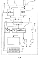
- FIG. 4 is a block diagram of an improved UMTS user mobile terminal according to the invention, suitable to interact with the two CELLULAR and BROADCAST networks.
- the terminal 20 comprises first of all a UMTS transceiver 22, which is connected to an antenna 24 for receiving a radio-frequency UMTS signal from the CELLULAR network, demodulate it and decode its physical layer (or radio layer) and for performing the reverse operations of encoding and modulation for transmission via the same antenna 24, as known to the person skilled in the art.
- the terminal 20 furthermore comprises video/audio decoding circuits 26, which decode the IP and higher levels (UDP or the like, as well as audio and video formats such as MPEG, RealAudio, et cetera), as known in the art, driving a graphical display 28 and a speaker 30.
- video/audio decoding circuits 26 which decode the IP and higher levels (UDP or the like, as well as audio and video formats such as MPEG, RealAudio, et cetera), as known in the art, driving a graphical display 28 and a speaker 30.
- Data transfer from the UMTS transceiver 22 to the decoding circuits 26 occurs by means of a controller 32, which has several management tasks that are known in the art, such as detecting call notifications arriving from the network and generating appropriate indications for the user (ring on the speaker 30 and/or information on the display 28), receiving commands from a keypad 34 of the terminal and generating the appropriate actions (call to the network, internal services of the terminal, et cetera) and of course transferring the received audio and video data to the video/audio decoding circuits 26.
- a controller 32 which has several management tasks that are known in the art, such as detecting call notifications arriving from the network and generating appropriate indications for the user (ring on the speaker 30 and/or information on the display 28), receiving commands from a keypad 34 of the terminal and generating the appropriate actions (call to the network, internal services of the terminal, et cetera) and of course transferring the received audio and video data to the video/audio decoding circuits 26.
- the terminal 20 furthermore comprises, again in a per se known manner, a microphone 36, which drives an encoder 38, which sends the encoded data to the controller 32, which also has the task of transferring them to the transceiver 22 for transmission toward the network.
- the terminal 20 in addition to the above functional components, which are substantially known, furthermore comprises a receiver 40, connected to the same antenna 24, for receiving signals from the BROADCAST network, demodulating them and decoding their physical layer (or radio layer), like the transceiver 22.
- the receiver 40 also is connected to the controller 32 in order to transfer thereto the received signals, so that the controller 32 in turn transfers them to the decoding circuits 26, in order to finally display them on the display 28 or play them on the speaker 30.
- the receiver 40 is normally inactive and can be activated by an enable command that it receives over a line 42 from the keypad 34, for example by pressing a button or by means of another procedure.
- the controller 32 in addition to the above mentioned conventional tasks, also has the task of receiving and routing to the decoding circuits 26 the signals that arrive from the receiver 40, and more specifically one of the channels comprised within said signals, according to the selection that arrives from the keypad.
- the user might scan the services or programs available at that time, by pressing a forward key, or, if he knows the program range, by directly selecting a specific program by means of a combination of keys.
- the controller 32 continues to communicate with the UMTS transceiver 32 in order to monitor any incoming calls and report them to the user.
- the keypad command with which the user accepts the call simultaneously disables the receiver 40.
- the user terminal furthermore comprises an SI table memory 44, to which the controller routes the data contained in the channel dedicated to said tables.
- the SI memory 44 communicates with the audio/video decoding circuits 26, in order to display them in menu form on the display 28.
- the user by means of the keypad 34, transmits his selection to the controller 32.
- the receiver should perform the following operations:
- the system described in the invention has important advantages, including the following: (1) the receiver uses homogeneous technologies and therefore requires lower development costs; (2) the DVB-type receiver has to demodulate an entire 5-15 Mbit/s stream, while the UMTS receiver can demodulate only the service used by the user (e.g. 64-200 kbit/s) and therefore has a far lower battery consumption.
Landscapes
- Engineering & Computer Science (AREA)
- Signal Processing (AREA)
- Multimedia (AREA)
- Computer Networks & Wireless Communication (AREA)
- Databases & Information Systems (AREA)
- General Engineering & Computer Science (AREA)
- Computer Security & Cryptography (AREA)
- Mobile Radio Communication Systems (AREA)
- Telephone Set Structure (AREA)
- Transmitters (AREA)
Abstract
Description
- The invention relates to a new system for broadcasting multimedia signals to UMTS mobile telephony terminals and to a mobile terminal for use with the system.
- Telecommunications systems such as PSTN, GSM and UMTS are conceived as bidirectional cellular systems with "one to one" connections, in which each transceiving terminal is controlled by a cellular network, with execution of a series of procedures suitable to locate it and keep it constantly in contact with the base station to which it is assigned. The data streams arriving at and leaving each terminal are unique and private for that terminal. Each communication begins with a bidirectional dialog with the base station and with a connection procedure in which the terminal is assigned a "channel" for transmission and reception, characterized by time or frequency divisions and, in the case of UMTS, by specific spread-spectrum sequences. Except for control information, there is no mode in which a terminal is in a receive-only state on a stream of services that are common to all users. In order to allow to sustain a large number of simultaneous private conversations among the terminals, the cellular network typically comprises a large number of low-power transmission antennas that cover small areas. The higher the interactive traffic that the network must guarantee, the smaller the size of the cells, which can even reach a density of 100 cells per square kilometer. Accordingly, the cost of a cellular telecommunications network is high and an increase in traffic entails additional network costs.
- More particularly, the UMTS system is furthermore designed to allow transmission and reception not only of audio signals typical of conventional telephony but also of pictures and videos and of multimedia signals in general, including in particular, in addition to private signals incoming from another user terminal, information and entertainment services, for example weather information in multimedia form, music video clips, sports-oriented and generalist newscasts. As known to the person skilled in the art, in the UMTS system these functions are implemented by adopting protocols for interchanging data in various formats, such as the Internet Protocol (IP), MPEG, and the like.
- In contrast to wireless telecommunications, radio broadcasting consists of unidirectional transmissions of the "one to many" type and is suitable for distributing content of the audio/video/multimedia type. Terrestrial radio and television broadcasting networks use high-power transmitters that cover vast service areas (for example entire administrative regions). Digital broadcasting services use the DVB (Digital Video Broadcasting) and DAB (Digital Audio Broadcasting) systems for the high-capacity unidirectional radio and television stream. The per-user costs of the network are low (on the order of a few tens of euro per family per year), and an increase in receivers (within the coverage area) does not entail increases in network costs. However, digital radio broadcasting networks in the VHF and UHF bands do not offer sufficient capacity to be used to carry Internet and telephony to the user.
- Attempts have been made to integrate radio and television digital services with cellular telephony and multimedia services toward mobile terminals, but so far these attempts have merely overlapped the two separate networks (broadcasting and telecommunications), keeping their respective technologies unchanged. The radio broadcasting network provides access to interactive services (for example e-commerce and Internet access) via the electronic program guide (EPG), but interactivity is managed by means of the cellular networks; in this scenario, the system is a DVB/UMTS (or DAB/UMTS) hybrid.
- A system of this kind is advocated in Horn U et al, "Interactive Mobile Streaming services the Convergence of Broadcast and Mobile Communication, EBU Review-Technical, European Broadcasting Union, Brussels, BE, no. 281, 21 September 1999 (1999-09-21), pages 14-19, XP000862720 ISSN: 0251-0936.
- A system built according to the indications of Horn is described in Kellerer et al.: "IP based enhanced Data Casting Services over Radio Broadcast Networks", Universal Multiservice Networks, 2000. ECUMN 2000. 1st European Conference, 2 October 2000 (2000-10-02), pages 195-203, XP010520270.
- Another system affine to the above, though its telecommunication network is based on the GSM standard rather than the UMTS standard, is described in European Telecommunications Standard Institute (ETSI); European Broadcasting Union (EBU): "EN 301 195 V1.1.1, Digital Video Broadcasting (DVB); Interaction channel through the Global System for Mobile Communications (GSM)" ETSI EN 301 195 V1.1.1, February 1999 (1999-02) pages 1-14, XP002248712
- WO 01/01712 relates to the centralized management of telecommunications parameters in different wireless telecommunication networks. A terminal can be configured to operate in any new heterogeneous environment (e.g. DAB, WLAN GSM), by receiving from a server the telecommunication parameters of the node providing the required service.
- The aim of the invention is now to provide a system for transmitting audio and video signals that allows to provide low-cost radio-broadcast audiovisual services to mobile user terminals capable of operating simultaneously as UMTS mobile telephony terminals, allowing the user to maintain the connection to both the cellular telecommunications network and the radio-broadcast audiovisual services (for example, the terminal must be able to ring due to an incoming call even while receiving a radio or TV program; the user, when receiving a radio/TV advert, must be able to activate a connection to the corresponding Website).
- An object of the invention is to provide said transmission system without an appreciable increase in the manufacturing cost and the size and weight of the mobile user terminal with respect to a conventional UMTS terminal.
- Another object is to provide said transmission system by using already-available radio broadcasting facilities and infrastructures, without the need for investments in new facilities.
- Another object is to make available to the user information and entertainment services at operating costs that are distinctly lower than those linked to the use of the UMTS telephone network.
- This aim, these objects and other objects and advantages that will become apparent from the continuation of the description are achieved by the invention with a network structure and network protocols having the features stated in
claim 1. The subordinate claims refer to other advantageous features of the invention. - The invention is now described in detail in some preferred embodiments thereof, given by way of nonlimitative example, with reference to the accompanying drawings, wherein:
- Figure 1 is a schematic view of a UMTS cellular network and of a transmission system according to the invention, both interacting with UMTS mobile telephony terminals;
- Figure 2 is a diagram of the protocol architecture of the system according to the invention;
- Figure 3 is an explanatory diagram that relates to the transport of descriptive tables used in the invention; and
- Figure 4 is a block diagram of a mobile telephony terminal that can be used in the system according to the invention.
- The invention is based on the use of two overlapping networks operating on separate frequency allocations. With reference to Figure 1, a plurality of
antennas 10 constitute the cells of a UMTS bidirectional telecommunications network with cellular coverage (hereinafter designated CELLULAR), for interactive services (such as for example telephony and Internet access); saidantennas 10 are connected to a plurality ofuser terminals 12, described hereinafter. Theuser terminals 12 can further be connected in a unidirectional broadcast network (hereinafter designated BROADCAST), characterized by high-power transmitters having a large coverage area, such as theradio transmitter 14, for broadcasting radio and television multimedia services on a band of carrier frequencies that is different from the carrier of the cellular network. - The invention is based on the concept of using the modes and protocols of the UMTS system both for the interactive services (conventional UMTS system) and for the services for radio broadcasting to mobile user terminals.
- While the terminals register themselves and remain hooked onto the UMTS cellular networks that carry the interactive services (telephone, Internet), the UMTS broadcast networks (hereinafter also referenced as B-UMTS), as proposed by the invention, carry unidirectional radio broadcasting signals (audio/video and multimedia) to said UMTS terminals, using multicast streaming protocols of the UDP-IP type. Said networks do not communicate bidirectionally with the individual terminals. Moreover, the broadcast network operates on frequencies that are different from those of the cellular network and uses existing radio broadcasting infrastructures.
- In the implementation of the invention, the UMTS system that operates on the broadcast-type network is modified so as not to perform the bidirectional procedures for terminal control: i.e. locating the terminal, sending/requesting calls, controlling power and transmission beam, assigning spread-spectrum sequences for communication. The transmission of a broadcast service is in fact not dependent on opening a connection with a specific terminal, but proceeds continuously, independently of the presence and number of receiving terminals (as occurs in the DVB or DAB broadcasting systems). The broadcast-type base station therefore uses IP protocols of the unidirectional type (UDP-IP type) and routes all the broadcast-type services to the radio frequency carrier, assigning to each service a specific spread-spectrum sequence, i.e., a specific UMTS "channel".
- The system according to the invention is based on communications protocols and procedures according to the 3GPP recommendation of UMTS. However, the standard for audio/video streaming services according to the 3GPP recommendation is based on the principle of demand ("on demand") by the user and on the allocation, with a bidirectional procedure, of a dedicated channel to each individual user. In order to avoid bidirectional procedures between the base station and the user terminal, one or more virtual terminals which, at the beginning of the transmission, by requesting the streaming services, start the procedures for selecting the transmission parameters for the various streaming channels. These parameters are then stored in the SI tables and sent to the users, according to the procedures established by the invention. Whenever a variation occurs in the offered services, the invention starts a new demand procedure on the part of the virtual terminals. This method allows to avoid modifications to the 3GPP standard of UMTS; if the standard introduces formats and procedures for auto/video streaming in broadcast mode, they might be used in the system according to the invention.
- The protocol architecture of the system according to the invention can be divided into two macrolayers, as shown in Figure 2: a radio macrolayer, based on the 3GPP standard, which comprises the physical layer (PL, Physical Layer, which refers to series 25.2 of the 3GPP standard), layer 2 (Data Link Layer, which refers to series 25.3 of the 3GPP standard), and layer 3 (Network Layer, which refers to series 25.4 of the 3GPP standard); and an upper macrolayer comprising IP and the upper-level protocols (UDP, RTP, et cetera).
- Again with reference to Figure 2, the IP upper-layer protocols defined in this specification are based on UDP. This does not rule out the use of other protocols for the upper layer.
- The Application Layer holds the content. Content, in general, can be constituted by audio and video or data. Audio and video is preferably encoded according to MPEG-4 (ISO/IEC 14496 standard and subsequent updates); encoding complexity can be limited to profiles (not described here) that establish the complexity of the decoding operations. Content can be encoded with other standards that are currently commercially available (Microsoft MPEG-4 format, RealVideo and RealAudio, et cetera) or will be developed in the future, no limitation to the possibilities of encoding the audio and video streams being intended here. The data can be files, images, Web pages. Encoding of data and of multimedia objects is not limited here to a particular standard.
- Content is organized in suitable structures, which can be easily encapsulated in the subsequent levels. It is possible to use RTP (standard by H. Schulzrinne, S. Casner, R. Frederick, V. Jacobson: "RTP: A Transport Protocol for Real-Time Applications", RFC1889, January 1996, but see also, for MPEG-4, Y. Kikuchi, T. Nomura, S. Fukunaga, Y. Matsui, H. Kimata: "RTP Payload Format for MPEG-4 Audio/Visual Streams", RFC3016, Proposed Standard, November 2000, and for other MPEG formats see D. Hoffman, G. Fernando, V. Goyal, M. Civanlar, "RTP Payload Format for MPEG1/MPEG2 Video", RFC2250, January 1998) in the case of MPEG-4 streams; on the other hand, session management protocols, such as RTSP (H. Schulzrinne, A. Rao, R. Lanphier: "Real Time Streaming Protocol (RTSP)", RFC2326, Proposed Standard, April 1998) and SDP (M. Handley, V. Jacobson: "SDP: Session Description Protocol", RFC2327, Proposed Standard, April 1998) are instead not used, since they require a return channel. The use of RTCP packets (see the RTP standard) or of protocols for quality of service control on a channel according to the invention is also not provided, but it is not ruled out in case of hybrid operation with a return channel (for example using the UMTS standard). In the case of data, Web pages, images or other multimedia objects, it is necessary to use protocols based on UDP, which do not use return channels. An example of data transfer protocol suitable for the above purpose is the one known as BTFTP ("Broadcast Trivial File Transfer Protocol", Internet Draft) and described in Italian patent application no. TO2000A000439, filed on 12 May 2000 by the Applicant.
- The UDP Layer, according to the standard (see J. Postel: "User Datagram Protocol", RFC768, August 1980), is the intermediate layer, enabling the use of protocols that do not have a return channel and are therefore suitable for the broadcast nature of the system. This layer contains transport functions and, partially owing to the unidirectional nature of the channel, session functions. With UDP it is possible to perform multiplexing/demultiplexing of the content of an individual IP address by virtue of the port mechanism.
- The IP Layer defines, according to the standard (see J. Postel: "Internet Protocol", RFC791, September 1981), the transport level and the syntax for the IP datagrams, which can be based on IPv4 but also, preferably, on IPv6. The address of the individual datagram is defined in the IP Layer. The UMTS Broadcast mode uses IP Multicast addresses to distribute content to all the terminals or to groups of terminals. IP Multicast addressing, in addition to rendering UMTS Broadcast perfectly interoperable with the Internet world, is particularly suitable for the broadcast nature of the system. IP Unicast addressing can be used for particular cases in which it is necessary to configure an individual UMTS terminal. The IP datagrams will have an MTU (Maximum Transfer Unit) suitable for encapsulation in the UMTS layer.
- As regards addressing, according to the invention it is defined by the IP Layer. Reference is made hereinafter to the IPv4 standard. The use of Multicast addresses for sending content (224.0.0.0 to 239.255.255.255; see also the document by J. Reynolds and J. Postel: "Assigned Numbers", RFC1700, October 1994) renders content sending flexible and standard.
- To encode the audio/video streams, the MPEG-4 encoding standard is used, in the version standardized by the MPEG group (ISO/IEC standard 14496, October 1998, and subsequent updates). The possibility of using standards other than RTP for the transport of MPEG-4 (Microsoft type) is not ruled out; this depends on the decoding capabilities of the UMTS terminal.
- As regards content description, one choice for providing the system consists in transporting all this information in the Application Layer of SC, in appropriate tables known as Service Information, or SI, although it is also possible to transport the information at the RADIO level. The SIs are in the form of ASCII text files whose content complies with the XML standard (see W3C Recommendation: "Extensible Markup Language (XML)", February 1998, 2nd Edition, October 2000). The Service Information of the SC channel must be transmitted on a known IP address and port; one embodiment provides for IP address 230.1.2.3 and port 53000.
- At the radio access level, according to the invention, the Broadcast-UMTS broadcasting station transmits:
- -- generic information for the actual operation of the user terminal, as specified in the UMTS standard, including system information common to the entire cell (for example an indicator of the scrambling sequence on the BCH transport channel), terminal synchronization information, pilot signals for estimating the transmission channel, which respectively correspond to physical channels P-CCPCH (Primary Common Control Physical Channel), PSCH (Physical Synchronization Channel) and CPICH (Common Pilot Channel) of the 3GPP standard.
- -- information on the broadcast services present on the radio-frequency channel. This information (known as Service Information) is meant to guide the user in choosing the services. In the preferred embodiment, this component takes the form of a table which contains the list of services present in the radio channel and the information required by the physical layer of the receiver in order to tune to said services (for example spreading sequence, scrambling sequence, encoding, et cetera); it is preferably but not exclusively carried by the FACH (Forward Access Channel) transport channel, which corresponds to the S-CCPCH (Secondary Common Control Physical Channel) physical channel, whose structure is given in ETSI recommendation TS 125 211 v.3.4.0., "Universal Mobile Telecommunications System (UMTS): Physical channels and mapping of transport channels onto physical channels (FDD)". As an alternative, the SI table can be transported by the PCH (Paging Channel) transport channel, which always corresponds to the S-CCPCH physical channel, furthermore associated with the PICH (Paging Indicator Channel) physical channel, normally used to notify the mobile terminal of the presence of information on the Paging Channel and used here to notify the mobile terminal of the presence of variations of the SI table contained in the Paging Channel. As additional alternatives, the SIs could be transported on the BCH channel or on a dedicated channel DCH. The information required by the receiver to connect to the Service Information transport channel (including the associated spreading sequence) are set beforehand or transmitted in the BCH channel and are known to the receiver. The transmission of this information channel occurs continuously and cyclically, so that each terminal, at power-on, can connect immediately to this channel and receive information regarding the services provided;
- -- the various multimedia audio/video streaming services, which travel on dedicated transport channels DCH, optionally divided over multiple physical channels, by means of the CCTrCH (Code Composite Transport Channel). Assignment of the physical channels is performed at the transmitter depending on the services to be broadcast and the characteristics of the transmission channel, and is stored in the SI table.
- Content description is not necessary but is preferred according to the invention, since it is the most straightforward means by which the terminal can gather information on the broadcasts in real time.
- The preferred embodiment of the invention is constituted by a signal that is compatible with the UMTS standard, is emitted by the transmitting station, and is formed by multiple information streams known as channels and characterized, at the RADIO level, by appropriate spread-spectrum sequences. One of the channels (the service channel, SC hereinafter for the sake of brevity), is dedicated, in the preferred embodiment, to the description of other channels and of the content associated with each one of said other channels. The SC channel must have characteristics that are known to the terminal (spread spectrum sequence), which connects to it during initialization. After connecting to the SC channel, the terminal extracts from it information on the other channels contained in the physical transmission channel (spreading sequences, bitrates and description of the content of the other subchannels from the SC channel). The receiver, after extracting the information contained in the SC channel, can offer a menu to the user and tune to the appropriate channel if selected by the user. As an alternative, the SI tables can be stored on an Internet site, downloaded by the user over the cellular UMTS network and stored in the terminal. Every time the administrator of the SI table varies its content, this must be reported to users (for example via SMS) so that they update the copy stored in the terminal.
- The user terminal, by connecting to the B-UMTS network, receives system information and pilot signals for synchronization and equalization of the transmission channel, and the SI table containing information on the available services. The table is stored in the receiver and is re-updated periodically or when signaled by the broadcasting station (for example on the PICH channel). When the user selects the intended program, the receiver searches in the table for the information regarding the physical channel or channels DCH to process and pass to the subsequent levels.
- The Service Information will use at least the tables described hereinafter:
- Table for associating spreading sequences and channels: with the following format (here, and hereinafter, the XML preamble is not inserted in order to provide the information in more concise form):
- <ssat>
- <channel c=c0 ss=s0></channel>
- <channel c=c1 ss=s1></channel>
- <channel c=c2 ss=s2></channel>
- ...
- </ssat>
- The <ssat> tag indicates the beginning of the table. The <channel> tag indicates the beginning of the description of the association between a spreading sequence and a channel. Channel number c0 is, for example, associated with spreading sequence s0. From this table, the receiver obtains the spreading sequences for each channel. The number c0 allows to reference the channel in a symbolic manner.
- Table for associating channels and channel content:
- <ccat>
- <content c=ch0>
- <description text="Description string"></description>
- <toc ad=a0 port=p0 display=d0></toc>
- <service ad=sa0 port=sp0 type="Service type"></service>
- <bitrate b=b0></bitrate>
- </content>
- ...
- </ccat>
- The <ccat> tag indicates the beginning of the table. The <content> tag indicates the beginning of the description of the association between a channel ch0 and the characteristics of that channel, as specified in the subsequent tags. The <description> tag associates with the channel a label, which can be displayed on the menu of the receiver and indicates the content of the channel in a manner that can be understood by the user (string of the text key). The <toc> tag specifies that at the multicast address a0, on port p0, a table providing a detailed description of the channel being considered is broadcast in a loop. The <toc> tag is therefore useful for channels that contain more than one audio/video or data stream. If the display key has a nonzero value, the table of contents <toc> is the first object to be displayed (therefore the user can navigate directly in a local menu of the channel). If display is equal to 0 or is not present, the service described in <service> is the first object that is presented (therefore the user sees immediately, for example, the audio/video stream of the channel). The <service> tag specifies the characteristics of the main service contained in the channel; sa0 is the multicast address, sp0 is the port; the type key specifies the type of service, as an Internet Media Type (see J. Reynolds, J. Postel: "Assigned Numbers", RFC1700, October 1994 and subsequent updates), an information that is required at the application level for content interpretation. The <bitrate> tag defines as b0 the bitrate of the channel. It should be noted that each one of the described tags is optional. The <content> tag must be repeated for each channel.
- Each channel dedicated to content can furthermore contain, as specified by the <toc> tag of the preceding table, a Table of Contents that describes in detail any additional services that are present.
- All channels that are not service channels (such as the SC) are meant to transport the audio/video and data content. Each channel can contain various audio/video and data streams, insofar as allowed by the band assigned to the channel. The specific Table of Contents of the channel has the following syntax:
- <ctoc>
- <subservice s=s0>
- <description text="Description string"></description>
- <service ad=sa0 port=sp0 type="Service type"></service>
- <bitrate b=b0></bitrate>
- </subservice>
- ...
- </ctoc>
- Transport of all the tables is performed on the Application Layer. The tables are repeated in the SC channel periodically. The tables of content <ctoc> of each channel, if present, are repeated periodically. The preferred embodiment uses BTFTP (Broadcast Trivial File Transfer Protocol) for transport of the tables over UDP, but other transport protocols are not ruled out.
- Figure 3 summarizes all of the above.
- The use of XML tables constitutes the preferred embodiment in the invention. An alternative embodiment consists in using tables encoded according to the MPEG and DVB-SI (ISO13818-1, EN300-468) standard, replacing the PID (packet identifier) information with channel information (number of channels). It should be noted that this replacement greatly restricts the possibility to describe the content at the Application level, since it is not possible to reference the various services optionally present on each channel at the present time. In this regard, subsequent DVB standardizations (for example the possibility to describe in detail in the DVB-SI services at the IP level) will be incorporated in subsequent implementations of the system being considered.
- Figure 4 is a block diagram of an improved UMTS user mobile terminal according to the invention, suitable to interact with the two CELLULAR and BROADCAST networks. The terminal 20 comprises first of all a
UMTS transceiver 22, which is connected to anantenna 24 for receiving a radio-frequency UMTS signal from the CELLULAR network, demodulate it and decode its physical layer (or radio layer) and for performing the reverse operations of encoding and modulation for transmission via thesame antenna 24, as known to the person skilled in the art. - The terminal 20 furthermore comprises video/
audio decoding circuits 26, which decode the IP and higher levels (UDP or the like, as well as audio and video formats such as MPEG, RealAudio, et cetera), as known in the art, driving agraphical display 28 and aspeaker 30. Data transfer from theUMTS transceiver 22 to thedecoding circuits 26 occurs by means of acontroller 32, which has several management tasks that are known in the art, such as detecting call notifications arriving from the network and generating appropriate indications for the user (ring on thespeaker 30 and/or information on the display 28), receiving commands from akeypad 34 of the terminal and generating the appropriate actions (call to the network, internal services of the terminal, et cetera) and of course transferring the received audio and video data to the video/audio decoding circuits 26. - The terminal 20 furthermore comprises, again in a per se known manner, a
microphone 36, which drives anencoder 38, which sends the encoded data to thecontroller 32, which also has the task of transferring them to thetransceiver 22 for transmission toward the network. - According to the invention, the terminal 20, in addition to the above functional components, which are substantially known, furthermore comprises a
receiver 40, connected to thesame antenna 24, for receiving signals from the BROADCAST network, demodulating them and decoding their physical layer (or radio layer), like thetransceiver 22. Thereceiver 40 also is connected to thecontroller 32 in order to transfer thereto the received signals, so that thecontroller 32 in turn transfers them to thedecoding circuits 26, in order to finally display them on thedisplay 28 or play them on thespeaker 30. However, thereceiver 40 is normally inactive and can be activated by an enable command that it receives over aline 42 from thekeypad 34, for example by pressing a button or by means of another procedure. - Therefore, according to the invention, the
controller 32, in addition to the above mentioned conventional tasks, also has the task of receiving and routing to thedecoding circuits 26 the signals that arrive from thereceiver 40, and more specifically one of the channels comprised within said signals, according to the selection that arrives from the keypad. For example, the user might scan the services or programs available at that time, by pressing a forward key, or, if he knows the program range, by directly selecting a specific program by means of a combination of keys. In any case, thecontroller 32 continues to communicate with theUMTS transceiver 32 in order to monitor any incoming calls and report them to the user. The keypad command with which the user accepts the call simultaneously disables thereceiver 40. - If the program descriptive tables are implemented, the user terminal furthermore comprises an
SI table memory 44, to which the controller routes the data contained in the channel dedicated to said tables. TheSI memory 44 communicates with the audio/video decoding circuits 26, in order to display them in menu form on thedisplay 28. The user, by means of thekeypad 34, transmits his selection to thecontroller 32. - The circuit modifications to be applied to a conventional controller for UMTS mobile telephony terminals in order to obtain the above described functions are obvious to the person skilled in the art and therefore are not described here for the sake of simplicity.
- In a typical scenario, the receiver should perform the following operations:
- -- initialization and connection to the SC channel, which contains the information on the other channels. This is possible because the characteristics of the SC channel are known;
- -- the terminal begins to receive the tables transmitted cyclically at the default address of the SC channel (IP 224.1.2.3, port 53000);
- -- once it has received the <ssat> table of association between sub-channels and spreading sequences, the receiver has all the information required to receive the other sub-channels;
- -- once it has received the <ccat> table, the receiver can show on the user's display a menu with the available content. The contents of the <description> tag of each <content> section is displayed;
- -- the user selects an item of the menu;
- -- the receiver, by knowing the channel number associated with that menu item, selects the spreading sequence that corresponds to the channel and starts to receive data;
- -- if the <toc> tag of the channel contains the display key and said key is not zero, the receiver shows on the display a submenu related to the channel;
- -- if the <toc> tag of the channel does not contain the display key or if said key is null, the receiver shows on the display the main service (for example an audio/video stream).
- With respect to a hybrid DVB/UMTS system, the system described in the invention has important advantages, including the following: (1) the receiver uses homogeneous technologies and therefore requires lower development costs; (2) the DVB-type receiver has to demodulate an entire 5-15 Mbit/s stream, while the UMTS receiver can demodulate only the service used by the user (e.g. 64-200 kbit/s) and therefore has a far lower battery consumption.
- In the above described embodiments of the invention it is of course possible to make modifications and variations in their nonessential aspects. The forms and methods of encapsulating the radio broadcast data, without losing compatibility with the UMTS system, might vary, especially at the uppermost layers, depending on the protocols that may be available also in the future. For example, the SI service tables might be omitted, especially if the multimedia services offered are limited in number, either allowing the user to browse in succession through the services offered at that time to choose his favorite, or determining once and for all the types of service available and their codes. The description of the user terminal should also be understood to be a preferred functional scheme, it being understood that the same functions can be obtained with other equivalent means.
Claims (14)
- A system for transmitting multimedia programs to a plurality of mobile telephony terminals (12), each comprising a UMTS transceiver (22) driving decoder means (26) associated with a graphical display (28) and a speaker (30), and connected to an antenna (24) for receiving a first frequency band belonging to a UMTS cell telephone network having a plurality of low-power cells (10); each mobile telephony terminal further comprising a receiver (40) connected to said antenna (24) for receiving a second frequency band from at least one high-power radio transmitter (14) capable of broadcasting multiple multimedia programs in said second frequency band, over an area that comprises a plurality of cells of the UMTS network, said receiver (40) being selectably connectable to said decoder means (26);
characterized in that said high-power radio transmitter (14) is arranged for broadcasting said plurality of multimedia programs in the form of signals compatible with the physical layer of the UMTS protocol and in respective UMTS channels identified by respective codes according to the UMTS protocol; and
in that said receiver (40) is arranged for decoding the signals transmitted by the high-power radio transmitter, extracting a signal from a selected one of said channels, and applying the decoded signal from the selected channel to said decoder means (26) associated with the display and the speaker. - The system for transmitting multimedia programs according to claim 1, characterized in that the signal broadcast by said radio transmitter (14) cyclically transports descriptive tables describing the multimedia services or programs contained in said channels.
- The system for transmitting multimedia programs according to claim 2, characterized in that said descriptive tables are transported in predetermined UMTS channel.
- The system for transmitting multimedia programs according to claim 3, characterized in that each one of said mobile telephony terminals (12) furthermore comprises a memory area (44) for storing said received descriptive tables, means (26) for displaying said descriptive tables on the display (28), and means (34) for receiving from the user commands for selecting one or more of said multimedia services or programs on the display and for enabling the reception of the chosen UMTS channel.
- The system for transmitting multimedia programs according to one of claims 1 to 4, characterized in that said receiver (40) in each one of said mobile telephony terminals (12) is normally deactivated and can be activated by the user by means of control means (36, 38).
- The system for transmitting multimedia programs according to claim 5, characterized in that each one of said mobile telephony terminals (12) is provided with visual and/or audio signaling means (28, 30) controlled by said UMTS transceiver (22), in order to notify the user of the arrival of a call from the UMTS cellular network while said receiver (40) is in operation.
- The system for transmitting multimedia programs according to one of claims 1 to 6, characterized in that the protocol architecture of the signals transmitted by said radio transmitter comprises a radio macrolayer, which is compatible with the UMTS protocol, and an upper macrolayer.
- The system for transmitting multimedia programs according to claim 7, characterized in that said upper macrolayer comprises an IP (Internet Protocol) layer, a UDP (User Datagram Protocol) layer, and an application layer (Application Layer).
- The system for transmitting multimedia programs according to claim 8, characterized in that said application layer uses an RTP (Real Time Protocol) protocol to transport the signals in MPEG-4 format.
- The system for transmitting multimedia programs according to claim 8, characterized in that said application layer uses a BTFTP (Broadcast Trivial File Transfer Protocol) protocol to transport text data.
- The system for transmitting multimedia programs according to claim 9, characterized in that said text data are descriptive tables describing the multimedia services or programs.
- A mobile terminal for use in the system according to one of claims 1 to 11, comprising a graphical display (28) driven by decoding circuits (26) for decoding audiovisual signals a UMTS transceiver (22) arranged for receiving UMTS signals from an antenna (24), and a controller (32) which connects the UMTS transceiver (22) to said decoding circuits (26), characterized in that the terminal further comprises a receiver (40) of signals that are compatible with the physical layer of the UMTS protocol, which can be activated by the user and tuned to receive and demodulate the signal emitted by said radio transmitter (14) and transfer it to the controller (32), and in that the controller is arranged for transferring to said decoding circuits (26) at least one of the channels of said received signal.
- The mobile terminal according to claim 12, characterized in that the controller (32) is preset to receive a channel selection from a keypad (34) and to select from the signal the chosen channel in order to route it to the decoding circuits (26).
- The mobile terminal according to claim 12 or 13, characterized in that it further comprises a memory (44) for tables describing the multimedia services or programs which is connected to the controller (32) and to the decoding circuits (26) in order to receive the text data contained in a preset channel and show a menu of programs on the display (28) of the terminal.
Applications Claiming Priority (2)
| Application Number | Priority Date | Filing Date | Title |
|---|---|---|---|
| IT2001TO000154A ITTO20010154A1 (en) | 2001-02-21 | 2001-02-21 | AUDIO AND VIDEO SIGNALS TRANSMISSION SYSTEM TO UMTS MOBILE TELEPHONE TERMINALS AND MOBILE TERMINAL FOR USE WITH THE SYSTEM. |
| ITTO010154 | 2001-02-21 |
Publications (3)
| Publication Number | Publication Date |
|---|---|
| EP1237302A2 EP1237302A2 (en) | 2002-09-04 |
| EP1237302A3 EP1237302A3 (en) | 2003-09-17 |
| EP1237302B1 true EP1237302B1 (en) | 2006-12-27 |
Family
ID=11458596
Family Applications (1)
| Application Number | Title | Priority Date | Filing Date |
|---|---|---|---|
| EP02075637A Expired - Lifetime EP1237302B1 (en) | 2001-02-21 | 2002-02-15 | A system for transmitting audio and video signals to UMTS mobile telephony terminals and a mobile terminal for use with the system |
Country Status (5)
| Country | Link |
|---|---|
| EP (1) | EP1237302B1 (en) |
| AT (1) | ATE349818T1 (en) |
| DE (1) | DE60216994T2 (en) |
| ES (1) | ES2278866T3 (en) |
| IT (1) | ITTO20010154A1 (en) |
Families Citing this family (5)
| Publication number | Priority date | Publication date | Assignee | Title |
|---|---|---|---|---|
| DE10308929B4 (en) * | 2003-02-28 | 2005-05-04 | Siemens Ag | Method for operating a data service in a radio communication system |
| CN100423511C (en) | 2003-03-03 | 2008-10-01 | 松下电器产业株式会社 | Mobile terminal having functions of program reception through broadcasting and through network communication, and program reception controlling method |
| DE102004004092B3 (en) * | 2004-01-27 | 2005-05-25 | Siemens Ag | Mobile terminal, especially mobile radio, for cellular mobile radio system suspends receiving packet-oriented broadcast signals during signaled time slice to receive radio call signals signaling telephone calls addressed to terminal |
| DE102004004093B3 (en) * | 2004-01-27 | 2005-09-01 | Siemens Ag | Mobile terminal for receiving packet-oriented broadcast signals |
| GB0402637D0 (en) | 2004-02-06 | 2004-03-10 | Nokia Corp | Mobile telecommunications apparatus |
Family Cites Families (2)
| Publication number | Priority date | Publication date | Assignee | Title |
|---|---|---|---|---|
| GB2313981B (en) * | 1996-06-06 | 2001-04-18 | Roke Manor Research | Assymetric communications channel for a portable computer |
| FI111317B (en) * | 1999-06-28 | 2003-06-30 | Domiras Oy | Centralized control of telecommunication parameters |
-
2001
- 2001-02-21 IT IT2001TO000154A patent/ITTO20010154A1/en unknown
-
2002
- 2002-02-15 ES ES02075637T patent/ES2278866T3/en not_active Expired - Lifetime
- 2002-02-15 EP EP02075637A patent/EP1237302B1/en not_active Expired - Lifetime
- 2002-02-15 DE DE60216994T patent/DE60216994T2/en not_active Expired - Lifetime
- 2002-02-15 AT AT02075637T patent/ATE349818T1/en active
Non-Patent Citations (1)
| Title |
|---|
| KELLERER ET AL.: "IP based enhanced Data Casting Services over Radio Broadcast Networks", UNIVERSAL MULTISERVICE NETWORKS, 2000. ECUMN 2000. 1ST EUROPEAN CONFERENCE, 2 October 2000 (2000-10-02), pages 195 - 203, XP010520270 * |
Also Published As
| Publication number | Publication date |
|---|---|
| ES2278866T3 (en) | 2007-08-16 |
| DE60216994D1 (en) | 2007-02-08 |
| ATE349818T1 (en) | 2007-01-15 |
| EP1237302A3 (en) | 2003-09-17 |
| ITTO20010154A0 (en) | 2001-02-21 |
| ITTO20010154A1 (en) | 2002-08-21 |
| DE60216994T2 (en) | 2007-05-03 |
| EP1237302A2 (en) | 2002-09-04 |
Similar Documents
| Publication | Publication Date | Title |
|---|---|---|
| US9277485B2 (en) | Method of transmitting and accessing network service data | |
| US7310330B2 (en) | Apparatus for providing broadcasting channel information in internet protocol based digital broadcasting system and method thereof | |
| US7779154B2 (en) | Mobile telecommunication networks and digital broadcasting services | |
| US20070240188A1 (en) | Datacasting | |
| CA2624048C (en) | A method for indicating service types in the service guide | |
| US9331802B2 (en) | Identifying scope ESG fragments and enabling hierarchy in the scope | |
| CN101455013B (en) | Service discovery section for mapping channel identifier to packet identifier | |
| RU2392745C2 (en) | Notice for terminal initialisation through service guide | |
| US20070234396A1 (en) | Method and apparatus for transmitting and receiving electronic service guide of interaction channel in a digital video broadcasting system | |
| CN101529895A (en) | Codec and session parameter change | |
| US7870377B2 (en) | Automatic electronic-service-guide selection | |
| US8451859B2 (en) | Packet type retransmission system for DMB service and retransmission device of DMB terminal | |
| US20100002696A1 (en) | Broadcast Content Encapsulation | |
| CN101390313B (en) | Method and apparatus for supporting mobility in dvb-h cbms system | |
| KR20050091016A (en) | Broadcast hand-over in a wireless network | |
| JP2010527175A (en) | Best effort service of digital broadcasting network | |
| CN101232613B (en) | Method of transmitting/receiving digital contents and apparatus for receiving digital contents | |
| US6763035B1 (en) | Method and device for transmitting information to the DVB network | |
| WO2009137976A1 (en) | System, method and device for transmitting electronic service guide information | |
| US20030097663A1 (en) | Method and apparatus for dynamic provisioning of IP-based services in a DVB network | |
| EP1237302B1 (en) | A system for transmitting audio and video signals to UMTS mobile telephony terminals and a mobile terminal for use with the system | |
| Acevedo et al. | Surveying mobile television | |
| KR20050036562A (en) | Digital cable network system and sending method for song service |
Legal Events
| Date | Code | Title | Description |
|---|---|---|---|
| PUAI | Public reference made under article 153(3) epc to a published international application that has entered the european phase |
Free format text: ORIGINAL CODE: 0009012 |
|
| AK | Designated contracting states |
Kind code of ref document: A2 Designated state(s): AT BE CH CY DE DK ES FI FR GB GR IE IT LI LU MC NL PT SE TR |
|
| AX | Request for extension of the european patent |
Free format text: AL;LT;LV;MK;RO;SI |
|
| PUAL | Search report despatched |
Free format text: ORIGINAL CODE: 0009013 |
|
| AK | Designated contracting states |
Kind code of ref document: A3 Designated state(s): AT BE CH CY DE DK ES FI FR GB GR IE IT LI LU MC NL PT SE TR |
|
| AX | Request for extension of the european patent |
Extension state: AL LT LV MK RO SI |
|
| RIC1 | Information provided on ipc code assigned before grant |
Ipc: 7H 04Q 7/32 B Ipc: 7H 04J 11/00 B Ipc: 7H 04B 7/26 A |
|
| 17P | Request for examination filed |
Effective date: 20040304 |
|
| AKX | Designation fees paid |
Designated state(s): AT BE CH CY DE DK ES FI FR GB GR IE IT LI LU MC NL PT SE TR |
|
| GRAP | Despatch of communication of intention to grant a patent |
Free format text: ORIGINAL CODE: EPIDOSNIGR1 |
|
| GRAS | Grant fee paid |
Free format text: ORIGINAL CODE: EPIDOSNIGR3 |
|
| GRAA | (expected) grant |
Free format text: ORIGINAL CODE: 0009210 |
|
| AK | Designated contracting states |
Kind code of ref document: B1 Designated state(s): AT BE CH CY DE DK ES FI FR GB GR IE IT LI LU MC NL PT SE TR |
|
| PG25 | Lapsed in a contracting state [announced via postgrant information from national office to epo] |
Ref country code: IT Free format text: LAPSE BECAUSE OF FAILURE TO SUBMIT A TRANSLATION OF THE DESCRIPTION OR TO PAY THE FEE WITHIN THE PRESCRIBED TIME-LIMIT;WARNING: LAPSES OF ITALIAN PATENTS WITH EFFECTIVE DATE BEFORE 2007 MAY HAVE OCCURRED AT ANY TIME BEFORE 2007. THE CORRECT EFFECTIVE DATE MAY BE DIFFERENT FROM THE ONE RECORDED. Effective date: 20061227 Ref country code: DK Free format text: LAPSE BECAUSE OF FAILURE TO SUBMIT A TRANSLATION OF THE DESCRIPTION OR TO PAY THE FEE WITHIN THE PRESCRIBED TIME-LIMIT Effective date: 20061227 Ref country code: NL Free format text: LAPSE BECAUSE OF FAILURE TO SUBMIT A TRANSLATION OF THE DESCRIPTION OR TO PAY THE FEE WITHIN THE PRESCRIBED TIME-LIMIT Effective date: 20061227 Ref country code: FI Free format text: LAPSE BECAUSE OF FAILURE TO SUBMIT A TRANSLATION OF THE DESCRIPTION OR TO PAY THE FEE WITHIN THE PRESCRIBED TIME-LIMIT Effective date: 20061227 |
|
| REG | Reference to a national code |
Ref country code: GB Ref legal event code: FG4D |
|
| REG | Reference to a national code |
Ref country code: IE Ref legal event code: FG4D |
|
| REF | Corresponds to: |
Ref document number: 60216994 Country of ref document: DE Date of ref document: 20070208 Kind code of ref document: P |
|
| PG25 | Lapsed in a contracting state [announced via postgrant information from national office to epo] |
Ref country code: SE Free format text: LAPSE BECAUSE OF FAILURE TO SUBMIT A TRANSLATION OF THE DESCRIPTION OR TO PAY THE FEE WITHIN THE PRESCRIBED TIME-LIMIT Effective date: 20070327 |
|
| PG25 | Lapsed in a contracting state [announced via postgrant information from national office to epo] |
Ref country code: PT Free format text: LAPSE BECAUSE OF FAILURE TO SUBMIT A TRANSLATION OF THE DESCRIPTION OR TO PAY THE FEE WITHIN THE PRESCRIBED TIME-LIMIT Effective date: 20070528 |
|
| NLV1 | Nl: lapsed or annulled due to failure to fulfill the requirements of art. 29p and 29m of the patents act | ||
| ET | Fr: translation filed | ||
| REG | Reference to a national code |
Ref country code: ES Ref legal event code: FG2A Ref document number: 2278866 Country of ref document: ES Kind code of ref document: T3 |
|
| PLBE | No opposition filed within time limit |
Free format text: ORIGINAL CODE: 0009261 |
|
| STAA | Information on the status of an ep patent application or granted ep patent |
Free format text: STATUS: NO OPPOSITION FILED WITHIN TIME LIMIT |
|
| 26N | No opposition filed |
Effective date: 20070928 |
|
| PG25 | Lapsed in a contracting state [announced via postgrant information from national office to epo] |
Ref country code: GR Free format text: LAPSE BECAUSE OF FAILURE TO SUBMIT A TRANSLATION OF THE DESCRIPTION OR TO PAY THE FEE WITHIN THE PRESCRIBED TIME-LIMIT Effective date: 20070328 |
|
| REG | Reference to a national code |
Ref country code: CH Ref legal event code: PCAR Free format text: ALDO ROEMPLER PATENTANWALT;BRENDENWEG 11 POSTFACH 154;9424 RHEINECK (CH) |
|
| PG25 | Lapsed in a contracting state [announced via postgrant information from national office to epo] |
Ref country code: CY Free format text: LAPSE BECAUSE OF FAILURE TO SUBMIT A TRANSLATION OF THE DESCRIPTION OR TO PAY THE FEE WITHIN THE PRESCRIBED TIME-LIMIT Effective date: 20061227 |
|
| PG25 | Lapsed in a contracting state [announced via postgrant information from national office to epo] |
Ref country code: TR Free format text: LAPSE BECAUSE OF FAILURE TO SUBMIT A TRANSLATION OF THE DESCRIPTION OR TO PAY THE FEE WITHIN THE PRESCRIBED TIME-LIMIT Effective date: 20061227 |
|
| REG | Reference to a national code |
Ref country code: FR Ref legal event code: PLFP Year of fee payment: 15 |
|
| PGFP | Annual fee paid to national office [announced via postgrant information from national office to epo] |
Ref country code: GB Payment date: 20151230 Year of fee payment: 15 Ref country code: IE Payment date: 20151223 Year of fee payment: 15 |
|
| PGFP | Annual fee paid to national office [announced via postgrant information from national office to epo] |
Ref country code: ES Payment date: 20151229 Year of fee payment: 15 Ref country code: MC Payment date: 20151230 Year of fee payment: 15 |
|
| PGFP | Annual fee paid to national office [announced via postgrant information from national office to epo] |
Ref country code: LU Payment date: 20160224 Year of fee payment: 15 |
|
| PGFP | Annual fee paid to national office [announced via postgrant information from national office to epo] |
Ref country code: CH Payment date: 20160120 Year of fee payment: 15 Ref country code: IT Payment date: 20151230 Year of fee payment: 15 Ref country code: DE Payment date: 20160225 Year of fee payment: 15 |
|
| PGFP | Annual fee paid to national office [announced via postgrant information from national office to epo] |
Ref country code: BE Payment date: 20160126 Year of fee payment: 15 Ref country code: FR Payment date: 20160114 Year of fee payment: 15 |
|
| PGFP | Annual fee paid to national office [announced via postgrant information from national office to epo] |
Ref country code: AT Payment date: 20160208 Year of fee payment: 15 |
|
| PG25 | Lapsed in a contracting state [announced via postgrant information from national office to epo] |
Ref country code: BE Free format text: LAPSE BECAUSE OF NON-PAYMENT OF DUE FEES Effective date: 20170228 |
|
| REG | Reference to a national code |
Ref country code: DE Ref legal event code: R119 Ref document number: 60216994 Country of ref document: DE |
|
| PG25 | Lapsed in a contracting state [announced via postgrant information from national office to epo] |
Ref country code: MC Free format text: LAPSE BECAUSE OF NON-PAYMENT OF DUE FEES Effective date: 20170228 |
|
| REG | Reference to a national code |
Ref country code: CH Ref legal event code: PL |
|
| REG | Reference to a national code |
Ref country code: AT Ref legal event code: MM01 Ref document number: 349818 Country of ref document: AT Kind code of ref document: T Effective date: 20170215 |
|
| GBPC | Gb: european patent ceased through non-payment of renewal fee |
Effective date: 20170215 |
|
| PG25 | Lapsed in a contracting state [announced via postgrant information from national office to epo] |
Ref country code: LI Free format text: LAPSE BECAUSE OF NON-PAYMENT OF DUE FEES Effective date: 20170228 Ref country code: AT Free format text: LAPSE BECAUSE OF NON-PAYMENT OF DUE FEES Effective date: 20170215 Ref country code: CH Free format text: LAPSE BECAUSE OF NON-PAYMENT OF DUE FEES Effective date: 20170228 |
|
| REG | Reference to a national code |
Ref country code: IE Ref legal event code: MM4A |
|
| REG | Reference to a national code |
Ref country code: FR Ref legal event code: ST Effective date: 20171031 |
|
| PG25 | Lapsed in a contracting state [announced via postgrant information from national office to epo] |
Ref country code: LU Free format text: LAPSE BECAUSE OF NON-PAYMENT OF DUE FEES Effective date: 20170215 |
|
| PG25 | Lapsed in a contracting state [announced via postgrant information from national office to epo] |
Ref country code: DE Free format text: LAPSE BECAUSE OF NON-PAYMENT OF DUE FEES Effective date: 20170901 Ref country code: FR Free format text: LAPSE BECAUSE OF NON-PAYMENT OF DUE FEES Effective date: 20170228 |
|
| REG | Reference to a national code |
Ref country code: BE Ref legal event code: MM Effective date: 20170228 |
|
| PG25 | Lapsed in a contracting state [announced via postgrant information from national office to epo] |
Ref country code: GB Free format text: LAPSE BECAUSE OF NON-PAYMENT OF DUE FEES Effective date: 20170215 Ref country code: IE Free format text: LAPSE BECAUSE OF NON-PAYMENT OF DUE FEES Effective date: 20170215 Ref country code: IT Free format text: LAPSE BECAUSE OF NON-PAYMENT OF DUE FEES Effective date: 20170215 |
|
| REG | Reference to a national code |
Ref country code: ES Ref legal event code: FD2A Effective date: 20180629 |
|
| PG25 | Lapsed in a contracting state [announced via postgrant information from national office to epo] |
Ref country code: ES Free format text: LAPSE BECAUSE OF NON-PAYMENT OF DUE FEES Effective date: 20170216 |