EP1234920B1 - Water supply connection for a cistern - Google Patents
Water supply connection for a cistern Download PDFInfo
- Publication number
- EP1234920B1 EP1234920B1 EP02000622A EP02000622A EP1234920B1 EP 1234920 B1 EP1234920 B1 EP 1234920B1 EP 02000622 A EP02000622 A EP 02000622A EP 02000622 A EP02000622 A EP 02000622A EP 1234920 B1 EP1234920 B1 EP 1234920B1
- Authority
- EP
- European Patent Office
- Prior art keywords
- cistern
- connecting sleeve
- seat
- receptacle
- flush box
- Prior art date
- Legal status (The legal status is an assumption and is not a legal conclusion. Google has not performed a legal analysis and makes no representation as to the accuracy of the status listed.)
- Expired - Lifetime
Links
Images


Classifications
-
- E—FIXED CONSTRUCTIONS
- E03—WATER SUPPLY; SEWERAGE
- E03D—WATER-CLOSETS OR URINALS WITH FLUSHING DEVICES; FLUSHING VALVES THEREFOR
- E03D1/00—Water flushing devices with cisterns ; Setting up a range of flushing devices or water-closets; Combinations of several flushing devices
- E03D1/30—Valves for high or low level cisterns; Their arrangement ; Flushing mechanisms in the cistern, optionally with provisions for a pre-or a post- flushing and for cutting off the flushing mechanism in case of leakage
- E03D1/32—Arrangement of inlet valves
-
- E—FIXED CONSTRUCTIONS
- E03—WATER SUPPLY; SEWERAGE
- E03D—WATER-CLOSETS OR URINALS WITH FLUSHING DEVICES; FLUSHING VALVES THEREFOR
- E03D1/00—Water flushing devices with cisterns ; Setting up a range of flushing devices or water-closets; Combinations of several flushing devices
Landscapes
- Health & Medical Sciences (AREA)
- Life Sciences & Earth Sciences (AREA)
- Engineering & Computer Science (AREA)
- Hydrology & Water Resources (AREA)
- Public Health (AREA)
- Water Supply & Treatment (AREA)
- Quick-Acting Or Multi-Walled Pipe Joints (AREA)
- Domestic Plumbing Installations (AREA)
- Sanitary Device For Flush Toilet (AREA)
- Non-Disconnectible Joints And Screw-Threaded Joints (AREA)
- Mechanical Coupling Of Light Guides (AREA)
- Branch Pipes, Bends, And The Like (AREA)
Abstract
Description
Die Erfindung betrifft einen Spülkasten mit einem Wasseranschluss umfassend einen Anschlussstutzen, der auf seiner einen Seite mit einer in dem Spülkasten vorgesehenen Einlaufeinheit zur Zuführung von Frischwasser verbindbar ist und auf seiner gegenüberliegenden Seite mit einem Zulaufrohr verbindbar ist, und mit einer Aufnahme, in welcher der Anschlussstutzen bewegbar gehalten ist. Solche Spülhasten sind aus der
Es sind Wasseranschlüsse für Spülkästen bekannt, bei denen ein Anschlußstutzen durch eine aus Kunststoff bestehende Wand eines Spülkastens durchgeführt ist. Dieser Anschlußstutzen ist mit Befestigungsmitteln an dem Gehäuse des Spülkastens fixiert, um eine Durchleitung des Wassers von einem Zulauf zu einer in dem Spülkasten angeordneten Einlaufeinheit zu ermöglichen. Bei solchen Wasseranschlüssen ist es nachteilig, dass die Lage des Anschlußstutzens durch die Befestigungsmittel vorgegeben ist. An dem außerhalb des Spülkastens angeordneten Ende des Anschlußstutzens müssen häufig Zulaufrohre und Umlenkungen befestigt werden, zu deren Montage Platz benötigt wird. Ferner müssen diese Bauteile teilweise angelötet werden, wobei der Abstand zu dem Spülkasten bzw. einer Styroporummantelung des Spülkastens sehr gering ist. Dadurch besteht bei der Montage die Gefahr, dass das Styroporgehäuse und/oder der Spülkasten bei der Montage beschädigt wird.There are water connections for cisterns known in which a connection piece is performed by a plastic wall of a cistern. This connection piece is fixed with fastening means on the housing of the cistern to allow passage of the water from an inlet to a arranged in the cistern inlet unit. In such water connections, it is disadvantageous that the position of the connecting piece is predetermined by the fastening means. At the arranged outside of the cistern end of the connection piece supply pipes and baffles must often be attached, for their installation space is needed. Furthermore, these components must be partially soldered, the distance to the cistern or a polystyrene jacket of the cistern is very low. As a result, during assembly, the Danger of damaging the polystyrene housing and / or cistern during installation.
Aus der
Die
Des weiteren ist aus der
Der vorliegenden Erfindung liegt die Aufgabe zugrunde, einen Spülkasten mit einem Wasseranschluss zu schaffen, bei dem die Montage der einzelnen Bauteile des Wasseranschlusses sowie des Zulaufrohres vereinfacht ist, und sich ein Anschlussstutzen des Wasseranschlusses in Längsrichtung an der Spülkastenwandung zuverlässig fixieren lässt.The present invention has for its object to provide a cistern with a water connection, in which the assembly of the individual components of the water connection and the inlet pipe is simplified, and can be reliably fix a connection piece of the water connection in the longitudinal direction of the Spülkastenwandung.
Diese Aufgabe wird durch einen Spülkasten mit den Merkmalen des Anspruchs 1 gelöst.This object is achieved by a cistern with the features of claim 1.
Bevorzugte Ausgestaltungen des erfindungsgemäßen Spülkastens sind in den Unteransprüchen angegeben.Preferred embodiments of the cistern according to the invention are specified in the subclaims.
Wenn der Anschlußstutzen bewegbar in einer Aufnahme gehalten ist, kann der Anschlußstutzen zur Montage in eine hervorstehende Position gezogen werden, so dass ein ausreichender Abstand zu dem Spülkasten und einer Styroporummantelung des Spülkastens besteht. Dadurch lassen sich die üblichen Befestigungsverfahren durch Schrauben, Löten oder sonstige Klemmverbindungen leichter montieren.If the connecting piece is movably held in a receptacle, the connecting piece can be pulled to a protruding position for mounting, so that there is a sufficient distance to the cistern and a Styrofoam casing of the cistern. As a result, the usual fastening methods by screws, soldering or other clamp connections easier to assemble.
Um den Anschlußstutzen dabei auf einfache Weise an der am Spülkasten angeordneten Aufnahme fixieren zu können, ist dieser vorzugsweise an der Aufnahme festklemmbar. Das Festklemmen kann dabei vorteilhaft durch an der Aufnahme angeordnete Rastmittel zur Festlegung des Anschlußstutzens erfolgen.In order to fix the connection piece in a simple way to the arranged on the cistern recording, this is preferably clamped to the receptacle. The clamping can be done advantageously by arranged on the receptacle locking means for fixing the connecting piece.
Um die Einheit aus Anschlußstutzen und Aufnahme an einem Spülkasten festzulegen, ist die Aufnahme mittels eines Klemmelementes an einer Wand eines Spülkastens festlegbar. Das Klemmelement kann als Mutter mit einem Klemmflansch ausgebildet sein, so dass durch einfaches Aufschrauben des Klemmelementes eine Festlegung erfolgt.To set the unit of connecting piece and recording on a cistern, the recording by means of a clamping element on a wall of a cistern is fixable. The clamping element may be formed as a nut with a clamping flange, so that by simply screwing the clamping element a determination is made.
Das Klemmelement verriegelt den Anschlußstutzen in der Aufnahme. Dadurch kann zur Montage das Klemmelement in einer geöffneten Stellung angeordnet sein, um den Anschlußstutzen frei an der Wand des Spülkastens bewegen zu können. Sobald die Montage beendet ist, kann mittels des Klemmelementes eine Verriegelung des Anschlußstutzens an der Wand des Spülkastens erfolgen.The clamping element locks the connecting piece in the receptacle. This can be arranged in an open position for mounting the clamping element to move the connection piece freely on the wall of the cistern can. Once the assembly is completed, can be done by means of the clamping element locking the connection piece on the wall of the cistern.
Um die Aufnahme schnell an einer Wand des Spülkastens zu montieren, ist vorzugsweise ein Flansch mit einem oder mehreren Zapfen an der Aufnahme angeformt, um die Aufnahme an dem Spülkasten mittels der Zapfen fixieren zu können.In order to mount the receptacle quickly on a wall of the cistern, a flange is preferably integrally formed with one or more pins on the receptacle in order to fix the receptacle on the cistern by means of the pin can.
Vorzugsweise sind die in dem Spülkasten angeordnete Einlaufeinheit und der Wasseranschluss mit einem flexiblen Rohr miteinander verbunden. Dadurch lässt sich der Anschlußstutzen auch bei vollständiger Montage innerhalb des Spülkastens noch in der Aufnahme bewegen.Preferably, the inlet unit arranged in the cistern and the water connection are connected to one another by means of a flexible tube. As a result, the connection piece can still move within the cistern even with complete assembly within the cistern.
Die Erfindung wird nachfolgend anhand eines Ausführungsbeispiels mit Bezug auf die beigefügten Zeichnungen näher erläutert. Es zeigen:
- Fig. 1
- eine geschnittene Seitenansicht eines Wasseranschlusses in der bewegbaren Position;
- Fig. 2
- eine geschnittene Seitenansicht des Wasseranschlusses der Fig. 1 in der festgelegten Position;
- Fig. 3A u. 3B
- zwei Ansichten des Anschlußstutzens des Wasseranschlusses der Fig. 1;
- Fig. 4A u. 4B
- zwei Ansichten der Aufnahme des Wasseranschlusses der Fig. 1, und
- Fig. 5A, 5B, 5C
- mehrere Ansichten des Klemmelementes des Wasseranschlusses der Fig. 1.
- Fig. 1
- a sectional side view of a water connection in the movable position;
- Fig. 2
- a sectional side view of the water supply of Figure 1 in the fixed position.
- Fig. 3A u. 3B
- two views of the connecting piece of the water connection of Fig. 1;
- Fig. 4A u. 4B
- two views of the receptacle of the water connection of Fig. 1, and
- Figs. 5A, 5B, 5C
- several views of the clamping element of the water connection of Fig. 1st
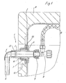
Ein Wasseranschluss 1 umfasst einen Anschlußstutzen 3, der durch eine Öffnung in einem Spülkasten 2 geführt ist. Der Anschlußstutzen 3 ist hier beispielsweise auf der nach außen gerichteten Seite mit einer Umlenkung 5 verbunden, die in den Anschlußstutzen 3 eingeschraubt ist. Die Umlenkung 5 ist mit einem Zulaufrohr 4 verbunden. Es sind hier verschiedene Anschlußvarianten denkbar.A water connection 1 comprises a connecting
Der Anschlußstutzen 3 ist bewegbar in einer Aufnahme 6 angeordnet, die an einer Wand des Spülkastens 2 vorfixiert ist. Um den Anschlußstutzen 3 an dem Spülkasten 2 zu verriegeln, ist ein Klemmelement 7 vorgesehen, das die Aufnahme 6 umgreift.The connecting
An der inneren Seite des Anschlußstutzens 3 ist ein Absperrventil 8 angeordnet, das mittels einer Mutter 9 auf den endseitigen Abschnitt des Anschlußstutzens 3 festklemmbar ist. Das Ventil 8 ist über ein flexibles Rohr 10 mit einer nicht dargestellten Einlaufeinheit des Spülkastens verbunden. Der Spülkasten 2 ist von einem Gehäuse 11 aus Styropor umgeben, in dem eine Öffnung 12 zur Durchführung des Wasseranschlusses 1 ausgespart ist.On the inner side of the connecting
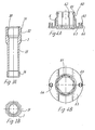
Wie in den Fig. 3A und 3B zu sehen ist, umfasst der Anschlußstutzen 3 an dem nach außen gerichteten Ende ein Innengewinde 30 und eine mehrkantig (z.B. achtkantig) ausgebildete Oberfläche 31, an der Schraubwerkzeug angreifen kann. Vorteilhaft kann sein, wenn die mehrkantig ausgebildete Oberfläche 31 asymmentrisch ausgebildet ist, damit das einmal befestigte Ventil bei einer erneuten Montage wieder lagegerecht zum Spülkasten montiert wird.As can be seen in Figures 3A and 3B, at the outwardly directed end, the connecting
An der Oberfläche 31 ist eine Rille 32 ausgespart, die zur axialen Festlegung des Anschlußstutzens 3 dient. In der Mitte des Anschlußstutzens 3 ist ein zylindrischer Abschnitt 33 ausgebildet, der einen geringeren Umfang besitzt als die Oberfläche 31. An dem gegenüberliegenden Ende ist ein Gewindeabschnitt 34 angeformt.On the
In den Fig. 4A und 4B ist die Aufnahme des Wasseranschlusses 1 dargestellt. Die Aufnahme 6 umfasst einen ringförmigen Abschnitt, an dem Wandelemente mit einem Halsabschnitt 60 und einer Verdickung 61 ausgebildet sind. Zwischen den einzelnen Wandelementen sind Schlitze 62 gebildet, so dass die Wandelemente um den Halsabschnitt 60 zu einem gewissen Grad verbiegbar sind. Die Aufnahme 6 umfasst ferner einen Flansch 63, an dem ein oder mehrere Zapfen 64 integral angeformt sind. An den Zapfen 64 sind Rastnasen 65 vorgesehen. Dadurch lässt sich die Aufnahme 6 mittels der Zapfen 64 und der Rastnasen 65 an der Wand des Spülkastens 2 vorfixieren, indem die Zapfen 64 durch entsprechende Öffnungen gesteckt werden. Die Aufnahme 6 ist vorzugsweise aus Kunststoff ausgebildet.In FIGS. 4A and 4B, the receptacle of the water connection 1 is shown. The
In den Fig. 5A, 5B und 5C ist das Klemmelement 7 des Wasseranschlusses 1 dargestellt, das einen Flansch 70 umfasst, in dem eine Rille 71 ausgespart ist. Die Rille 71 übergreift die Rastnasen 65 der Zapfen 64 der Aufnahme 6 im montierten Zustand. Das Klemmelement 7 ist mit einem Innengewinde 72 versehen, das auf die Aufnahme 6 aufschraubbar ist. An der dem Flansch 70 gegenüberliegenden Seite ist eine konische Verjüngung 73 vorgesehen, die zur Verriegelung des Anschlußstutzens 3 eingesetzt wird. Am Umfang ist eine mehreckige Oberfläche 74 ausgebildet, an der ein Werkzeug angreifen kann.In FIGS. 5A, 5B and 5C, the clamping
Zur Montage wird zunächst die Aufnahme 6 an einer Wand bzw. Decke des Spülkastens 2 fixiert, wobei die Zapfen 64 mit den Rastnasen 65 eine Vorfixierung bereitstellen. Der Anschlußstutzen 3 ist so in die Aufnahme 6 einfügbar und kann vollständig mit dem Ventil 8 bzw. dem Zulaufrohr 4 verbunden werden. In dieser Position ist der Anschlußstutzen 3 innerhalb der Aufnahme 6 beweglich gehalten. Zur Festlegung der Aufnahme 3 wird der Anschlußstutzen 3 in die Aufnahme 6 eingefügt, bis die verdickten Abschnitte 61 in die Rillen 32 eingreifen. Der Anschlußstutzen 3 ist klemmend in der Aufnahme 6 gehalten. Zur Verriegelung des Anschlußstutzens 3 wird anschließend das Klemmelement 7 auf die Aufnahme 6 aufgeschraubt, wobei einerseits die Aufnahme 6 an dem Spülkasten 2 festgelegt wird und andererseits der verdickte Abschnitt 61 mittels des konischen Abschnittes 73 des Klemmelementes 7 in die Rille 32 des Anschlußstutzens 3 gedrückt wird. Dadurch wird der Anschlußstutzen 3 an der Aufnahme 6 verriegelt.For mounting, the
Claims (6)
- A flush box (2) with a water supply (1) comprising a connecting sleeve (3) which is connectable on one side thereof to an inflow unit provided in the flush box for the supply of fresh water and which is connectable on its opposite side to a supply pipe (4), and with a seat (6) in which the connecting sleeve (4) is moveably supported, characterized in that the seat (6) comprises locking means (61) for locking engagement with the connecting sleeve (3) for fixing the connecting sleeve (3), that the seat (6) is provided with a clamping element (7) by means of which the seat can be fixed at a wall of the flush box, and that the clamping element (7) latches the connecting sleeve (3) at the seat in the locked condition.
- A flush box as claimed in claim 1, characterized in that the connecting sleeve (3) can be clamped in the seat (6).
- A flush box as claimed in claim 1 or 2, characterized in that the clamping element (7) is formed as a nut with a clamping flange (70).
- A flush box as claimed in one of claims 1 to 3, characterized in that a flange (63) is molded to the seat (6), on which pins (64) for pre-fixing the seat (6) at a wall of the flush box (2) are provided.
- A flush box as claimed in one of claims 1 to 4, characterized in that the connecting sleeve (3) has a surface (31) with an asymmetric cross-section for positioning the connecting sleeve (3) in the seat (6).
- A flush box as claimed in one of claims 1 to 5, characterized in that a flexible tube (10) is mounted between the inflow unit and the water supply (1).
Applications Claiming Priority (2)
| Application Number | Priority Date | Filing Date | Title |
|---|---|---|---|
| DE20103210U DE20103210U1 (en) | 2001-02-23 | 2001-02-23 | Water connection for a cistern |
| DE20103210U | 2001-02-23 |
Publications (2)
| Publication Number | Publication Date |
|---|---|
| EP1234920A1 EP1234920A1 (en) | 2002-08-28 |
| EP1234920B1 true EP1234920B1 (en) | 2007-11-07 |
Family
ID=7953422
Family Applications (1)
| Application Number | Title | Priority Date | Filing Date |
|---|---|---|---|
| EP02000622A Expired - Lifetime EP1234920B1 (en) | 2001-02-23 | 2002-01-11 | Water supply connection for a cistern |
Country Status (3)
| Country | Link |
|---|---|
| EP (1) | EP1234920B1 (en) |
| AT (1) | ATE377677T1 (en) |
| DE (2) | DE20103210U1 (en) |
Families Citing this family (3)
| Publication number | Priority date | Publication date | Assignee | Title |
|---|---|---|---|---|
| FR2932201B1 (en) * | 2008-06-09 | 2013-06-14 | Wirquin Plastiques Sa | ABOUT CONNECTION TO BE MOUNTED ON A WATER HUNTING RESERVOIR HAVING A PLASTIC ZONE AND A SECOND ZONE, THREADED, IN A METALLIC MATERIAL |
| DE102008054777A1 (en) * | 2008-12-16 | 2010-06-17 | BSH Bosch und Siemens Hausgeräte GmbH | Domestic appliance with a gas pipe |
| DE102017103947A1 (en) * | 2017-02-24 | 2018-08-30 | Tece Gmbh | Universal filling valve set |
Citations (1)
| Publication number | Priority date | Publication date | Assignee | Title |
|---|---|---|---|---|
| US3654382A (en) * | 1970-06-01 | 1972-04-04 | Arco Ind Corp | Grommet construction |
Family Cites Families (4)
| Publication number | Priority date | Publication date | Assignee | Title |
|---|---|---|---|---|
| US2985291A (en) * | 1958-04-28 | 1961-05-23 | Schoepe Adolf | Composite seal construction |
| FR2663970B1 (en) * | 1990-06-29 | 1997-04-04 | Torcy Sa Ets | FLOAT DEVICE FOR CONTROLLING THE FILLING OF A WATER FLUSHING TANK. |
| FR2780080B1 (en) * | 1998-06-22 | 2000-08-11 | Regiplast | WATER TANK AND ITS FEEDING DEVICE |
| DE29816510U1 (en) * | 1998-09-15 | 1998-12-10 | Franz Viegener Ii Gmbh & Co Kg | Junction box with inserted elbow for a toilet cistern |
-
2001
- 2001-02-23 DE DE20103210U patent/DE20103210U1/en not_active Expired - Lifetime
-
2002
- 2002-01-11 EP EP02000622A patent/EP1234920B1/en not_active Expired - Lifetime
- 2002-01-11 AT AT02000622T patent/ATE377677T1/en active
- 2002-01-11 DE DE50211152T patent/DE50211152D1/en not_active Expired - Lifetime
Patent Citations (1)
| Publication number | Priority date | Publication date | Assignee | Title |
|---|---|---|---|---|
| US3654382A (en) * | 1970-06-01 | 1972-04-04 | Arco Ind Corp | Grommet construction |
Also Published As
| Publication number | Publication date |
|---|---|
| EP1234920A1 (en) | 2002-08-28 |
| DE50211152D1 (en) | 2007-12-20 |
| DE20103210U1 (en) | 2002-07-04 |
| ATE377677T1 (en) | 2007-11-15 |
Similar Documents
| Publication | Publication Date | Title |
|---|---|---|
| EP2806199B1 (en) | Cable bushing | |
| DE102012108400B4 (en) | Standpipe arrangement including attachment for receiving and supplying gas to aerators in a sewage treatment tank | |
| DE202010009280U1 (en) | Fastening device for fastening a wall-mounted sanitary object | |
| DE102005053240A1 (en) | Faucet-quick installation nut | |
| DE69818390T2 (en) | Mechanism for fastening elements carrying pressure medium to a frame element | |
| EP3400342B1 (en) | Valve armature for the filling of a sanitary cistern and sanitary cistern having a valve armature of this type | |
| EP1798348B1 (en) | Mixer tap | |
| EP1234920B1 (en) | Water supply connection for a cistern | |
| DE102015110876A1 (en) | Fluidumleitvorrichtung | |
| WO2009092632A1 (en) | Injection spigot | |
| EP1484544B1 (en) | Conduit feed-through for the installation of a sanitary tube through a wall | |
| DE10251078B3 (en) | Sealing system for the space in the transition area between two well pipes of different diameters and installation tools for this | |
| DE10150180A1 (en) | Aerating system for liquids, and especially waste water for treating sewage, has an elastic bush at mounting of aerating element at distribution pipe to compensate for flow forces | |
| DE202017105078U1 (en) | joint assembly | |
| DE102022122848B3 (en) | Connecting bracket and installation set | |
| AT412220B (en) | HYDRANT | |
| DE3535327C2 (en) | ||
| DE3604932A1 (en) | Multiple-connection fitting for a connection box for service-water installations | |
| DE10357646B4 (en) | Wall bushing | |
| DE102012109033B4 (en) | Connection device | |
| DE19813409C2 (en) | Device for coupling the rotary table connection of a drilling device to a pipe adapter | |
| DE19630029A1 (en) | Valve tapping fitting for plastics pipelines under pressure | |
| DE102014114902A1 (en) | Shut-off and flow control tap | |
| DE102006042407B4 (en) | System component for laying ventilation pipes in concrete ceilings | |
| DE3617822A1 (en) | GAS MACHINE QUICK CONNECTION |
Legal Events
| Date | Code | Title | Description |
|---|---|---|---|
| PUAI | Public reference made under article 153(3) epc to a published international application that has entered the european phase |
Free format text: ORIGINAL CODE: 0009012 |
|
| AK | Designated contracting states |
Kind code of ref document: A1 Designated state(s): AT BE CH CY DE DK ES FI FR GB GR IE IT LI LU MC NL PT SE TR |
|
| AX | Request for extension of the european patent |
Free format text: AL;LT;LV;MK;RO;SI |
|
| 17P | Request for examination filed |
Effective date: 20021030 |
|
| AKX | Designation fees paid |
Designated state(s): AT CH DE LI NL |
|
| RAP1 | Party data changed (applicant data changed or rights of an application transferred) |
Owner name: VIEGA GMBH & CO. KG. |
|
| 17Q | First examination report despatched |
Effective date: 20041109 |
|
| GRAP | Despatch of communication of intention to grant a patent |
Free format text: ORIGINAL CODE: EPIDOSNIGR1 |
|
| GRAS | Grant fee paid |
Free format text: ORIGINAL CODE: EPIDOSNIGR3 |
|
| GRAA | (expected) grant |
Free format text: ORIGINAL CODE: 0009210 |
|
| AK | Designated contracting states |
Kind code of ref document: B1 Designated state(s): AT CH DE LI NL |
|
| REG | Reference to a national code |
Ref country code: CH Ref legal event code: EP |
|
| REF | Corresponds to: |
Ref document number: 50211152 Country of ref document: DE Date of ref document: 20071220 Kind code of ref document: P |
|
| REG | Reference to a national code |
Ref country code: CH Ref legal event code: NV Representative=s name: TROESCH SCHEIDEGGER WERNER AG |
|
| PLBE | No opposition filed within time limit |
Free format text: ORIGINAL CODE: 0009261 |
|
| STAA | Information on the status of an ep patent application or granted ep patent |
Free format text: STATUS: NO OPPOSITION FILED WITHIN TIME LIMIT |
|
| 26N | No opposition filed |
Effective date: 20080808 |
|
| REG | Reference to a national code |
Ref country code: DE Ref legal event code: R082 Ref document number: 50211152 Country of ref document: DE Representative=s name: COHAUSZ & FLORACK PATENT- UND RECHTSANWAELTE P, DE Ref country code: DE Ref legal event code: R081 Ref document number: 50211152 Country of ref document: DE Owner name: VIEGA TECHNOLOGY GMBH & CO. KG, DE Free format text: FORMER OWNER: VIEGA GMBH & CO. KG, 57439 ATTENDORN, DE |
|
| REG | Reference to a national code |
Ref country code: AT Ref legal event code: PC Ref document number: 377677 Country of ref document: AT Kind code of ref document: T Owner name: VIEGA TECHNOLOGY GMBH & CO. KG, DE Effective date: 20170512 |
|
| REG | Reference to a national code |
Ref country code: NL Ref legal event code: PD Owner name: VIEGA TECHNOLOGY GMBH & CO. KG; DE Free format text: DETAILS ASSIGNMENT: CHANGE OF OWNER(S), ASSIGNMENT; FORMER OWNER NAME: VIEGA GMBH & CO. KG. Effective date: 20170412 |
|
| REG | Reference to a national code |
Ref country code: CH Ref legal event code: PUE Owner name: VIEGA TECHNOLOGY GMBH AND CO. KG, DE Free format text: FORMER OWNER: VIEGA GMBH AND CO. KG, DE |
|
| PGFP | Annual fee paid to national office [announced via postgrant information from national office to epo] |
Ref country code: CH Payment date: 20210118 Year of fee payment: 20 Ref country code: NL Payment date: 20210118 Year of fee payment: 20 |
|
| PGFP | Annual fee paid to national office [announced via postgrant information from national office to epo] |
Ref country code: AT Payment date: 20210119 Year of fee payment: 20 Ref country code: DE Payment date: 20210119 Year of fee payment: 20 |
|
| REG | Reference to a national code |
Ref country code: DE Ref legal event code: R071 Ref document number: 50211152 Country of ref document: DE |
|
| REG | Reference to a national code |
Ref country code: NL Ref legal event code: MK Effective date: 20220110 |
|
| REG | Reference to a national code |
Ref country code: CH Ref legal event code: PL |
|
| REG | Reference to a national code |
Ref country code: AT Ref legal event code: MK07 Ref document number: 377677 Country of ref document: AT Kind code of ref document: T Effective date: 20220111 |