EP1234632A1 - Kinematic device for programmably supporting and positioning an end element in a machine or an instrument - Google Patents
Kinematic device for programmably supporting and positioning an end element in a machine or an instrument Download PDFInfo
- Publication number
- EP1234632A1 EP1234632A1 EP01810193A EP01810193A EP1234632A1 EP 1234632 A1 EP1234632 A1 EP 1234632A1 EP 01810193 A EP01810193 A EP 01810193A EP 01810193 A EP01810193 A EP 01810193A EP 1234632 A1 EP1234632 A1 EP 1234632A1
- Authority
- EP
- European Patent Office
- Prior art keywords
- nacelle
- terminal element
- guided
- support
- joints
- Prior art date
- Legal status (The legal status is an assumption and is not a legal conclusion. Google has not performed a legal analysis and makes no representation as to the accuracy of the status listed.)
- Withdrawn
Links
Images


Classifications
-
- B—PERFORMING OPERATIONS; TRANSPORTING
- B25—HAND TOOLS; PORTABLE POWER-DRIVEN TOOLS; MANIPULATORS
- B25J—MANIPULATORS; CHAMBERS PROVIDED WITH MANIPULATION DEVICES
- B25J17/00—Joints
- B25J17/02—Wrist joints
- B25J17/0258—Two-dimensional joints
- B25J17/0266—Two-dimensional joints comprising more than two actuating or connecting rods
-
- B—PERFORMING OPERATIONS; TRANSPORTING
- B25—HAND TOOLS; PORTABLE POWER-DRIVEN TOOLS; MANIPULATORS
- B25J—MANIPULATORS; CHAMBERS PROVIDED WITH MANIPULATION DEVICES
- B25J17/00—Joints
- B25J17/02—Wrist joints
-
- B—PERFORMING OPERATIONS; TRANSPORTING
- B23—MACHINE TOOLS; METAL-WORKING NOT OTHERWISE PROVIDED FOR
- B23Q—DETAILS, COMPONENTS, OR ACCESSORIES FOR MACHINE TOOLS, e.g. ARRANGEMENTS FOR COPYING OR CONTROLLING; MACHINE TOOLS IN GENERAL CHARACTERISED BY THE CONSTRUCTION OF PARTICULAR DETAILS OR COMPONENTS; COMBINATIONS OR ASSOCIATIONS OF METAL-WORKING MACHINES, NOT DIRECTED TO A PARTICULAR RESULT
- B23Q1/00—Members which are comprised in the general build-up of a form of machine, particularly relatively large fixed members
- B23Q1/25—Movable or adjustable work or tool supports
- B23Q1/44—Movable or adjustable work or tool supports using particular mechanisms
- B23Q1/48—Movable or adjustable work or tool supports using particular mechanisms with sliding pairs and rotating pairs
- B23Q1/4852—Movable or adjustable work or tool supports using particular mechanisms with sliding pairs and rotating pairs a single sliding pair followed perpendicularly by a single rotating pair
-
- B—PERFORMING OPERATIONS; TRANSPORTING
- B23—MACHINE TOOLS; METAL-WORKING NOT OTHERWISE PROVIDED FOR
- B23Q—DETAILS, COMPONENTS, OR ACCESSORIES FOR MACHINE TOOLS, e.g. ARRANGEMENTS FOR COPYING OR CONTROLLING; MACHINE TOOLS IN GENERAL CHARACTERISED BY THE CONSTRUCTION OF PARTICULAR DETAILS OR COMPONENTS; COMBINATIONS OR ASSOCIATIONS OF METAL-WORKING MACHINES, NOT DIRECTED TO A PARTICULAR RESULT
- B23Q1/00—Members which are comprised in the general build-up of a form of machine, particularly relatively large fixed members
- B23Q1/25—Movable or adjustable work or tool supports
- B23Q1/44—Movable or adjustable work or tool supports using particular mechanisms
- B23Q1/50—Movable or adjustable work or tool supports using particular mechanisms with rotating pairs only, the rotating pairs being the first two elements of the mechanism
- B23Q1/54—Movable or adjustable work or tool supports using particular mechanisms with rotating pairs only, the rotating pairs being the first two elements of the mechanism two rotating pairs only
- B23Q1/545—Movable or adjustable work or tool supports using particular mechanisms with rotating pairs only, the rotating pairs being the first two elements of the mechanism two rotating pairs only comprising spherical surfaces
- B23Q1/5462—Movable or adjustable work or tool supports using particular mechanisms with rotating pairs only, the rotating pairs being the first two elements of the mechanism two rotating pairs only comprising spherical surfaces with one supplementary sliding pair
-
- B—PERFORMING OPERATIONS; TRANSPORTING
- B25—HAND TOOLS; PORTABLE POWER-DRIVEN TOOLS; MANIPULATORS
- B25J—MANIPULATORS; CHAMBERS PROVIDED WITH MANIPULATION DEVICES
- B25J9/00—Programme-controlled manipulators
- B25J9/003—Programme-controlled manipulators having parallel kinematics
- B25J9/0033—Programme-controlled manipulators having parallel kinematics with kinematics chains having a prismatic joint at the base
- B25J9/0039—Programme-controlled manipulators having parallel kinematics with kinematics chains having a prismatic joint at the base with kinematics chains of the type prismatic-spherical-spherical
-
- B—PERFORMING OPERATIONS; TRANSPORTING
- B25—HAND TOOLS; PORTABLE POWER-DRIVEN TOOLS; MANIPULATORS
- B25J—MANIPULATORS; CHAMBERS PROVIDED WITH MANIPULATION DEVICES
- B25J9/00—Programme-controlled manipulators
- B25J9/003—Programme-controlled manipulators having parallel kinematics
- B25J9/0072—Programme-controlled manipulators having parallel kinematics of the hybrid type, i.e. having different kinematics chains
-
- Y—GENERAL TAGGING OF NEW TECHNOLOGICAL DEVELOPMENTS; GENERAL TAGGING OF CROSS-SECTIONAL TECHNOLOGIES SPANNING OVER SEVERAL SECTIONS OF THE IPC; TECHNICAL SUBJECTS COVERED BY FORMER USPC CROSS-REFERENCE ART COLLECTIONS [XRACs] AND DIGESTS
- Y10—TECHNICAL SUBJECTS COVERED BY FORMER USPC
- Y10T—TECHNICAL SUBJECTS COVERED BY FORMER US CLASSIFICATION
- Y10T409/00—Gear cutting, milling, or planing
- Y10T409/30—Milling
- Y10T409/306664—Milling including means to infeed rotary cutter toward work
- Y10T409/307672—Angularly adjustable cutter head
-
- Y—GENERAL TAGGING OF NEW TECHNOLOGICAL DEVELOPMENTS; GENERAL TAGGING OF CROSS-SECTIONAL TECHNOLOGIES SPANNING OVER SEVERAL SECTIONS OF THE IPC; TECHNICAL SUBJECTS COVERED BY FORMER USPC CROSS-REFERENCE ART COLLECTIONS [XRACs] AND DIGESTS
- Y10—TECHNICAL SUBJECTS COVERED BY FORMER USPC
- Y10T—TECHNICAL SUBJECTS COVERED BY FORMER US CLASSIFICATION
- Y10T409/00—Gear cutting, milling, or planing
- Y10T409/30—Milling
- Y10T409/309576—Machine frame
-
- Y—GENERAL TAGGING OF NEW TECHNOLOGICAL DEVELOPMENTS; GENERAL TAGGING OF CROSS-SECTIONAL TECHNOLOGIES SPANNING OVER SEVERAL SECTIONS OF THE IPC; TECHNICAL SUBJECTS COVERED BY FORMER USPC CROSS-REFERENCE ART COLLECTIONS [XRACs] AND DIGESTS
- Y10—TECHNICAL SUBJECTS COVERED BY FORMER USPC
- Y10T—TECHNICAL SUBJECTS COVERED BY FORMER US CLASSIFICATION
- Y10T74/00—Machine element or mechanism
- Y10T74/20—Control lever and linkage systems
- Y10T74/20207—Multiple controlling elements for single controlled element
- Y10T74/20305—Robotic arm
- Y10T74/20329—Joint between elements
- Y10T74/20335—Wrist
Definitions
- the present invention belongs to the technical field of kinematic support and displacement devices which allow to control in a programmable way and with a high precision of displacements in translation and / or in rotation of a terminal element in a working field predetermined.
- the terminal element can be a machining tool (spindle, laser, water jet, EDM, etc.) or a carrier parts in case the device is incorporated in a center machining, for example, or a gripping instrument, a mounting tool, measurement sensor, interface user for force feedback joystick, antenna, camera holder, etc., in the case of transfer machines, assembly robots, packaging machines, instruments medical devices, etc., or any device where high precision positioning or displacement and / or high dynamics is required.
- machining tool spindle, laser, water jet, EDM, etc.
- carrier parts in case the device is incorporated in a center machining, for example, or a gripping instrument, a mounting tool, measurement sensor, interface user for force feedback joystick, antenna, camera holder, etc., in the case of transfer machines, assembly robots, packaging machines, instruments medical devices, etc., or any device where high precision positioning or displacement and / or high dynamics is required.
- the purpose of the present invention is to provide a parallel kinematic device that responds better and more comprehensively to the needs indicated above than the known devices and which in particular offers speed and working precision as high as possible while allowing to program element movements terminal in a work area with such a large volume as possible and ensuring consistent behavior in this volume of work.
- the device according to the present invention has the characteristics defined according to appended claims, the content of which must be considered as part of this description.
- the term “useful joint” a joint necessary for the operation of the device to which it is attached, by opposition to joints that allow mobility internal, as for example in the case of a bar provided with two ball joints at its ends and which has the possibility of turn on itself, which does not provide any functionality.
- the terminal element can be a clamp, or a suction cup, or any other type of grip.
- this terminal element can be either a spindle carrying a cutter, a grinding wheel, a drill bit, workpiece holder, etc. water jet, laser cutting, EDM, deburring, sandblasting, painting, polishing, etc.
- the machine can be equipped with grippers and machining tools on board the terminal element, for example mounted on a revolver head, or associated with an active or passive tool changer (i.e. a stock of tools and / or workpiece holders).
- the terminal element is symbolized by an engine body which is associated in a way rigid to a rigid part called a nacelle, the latter making part of the support and displacement structure.
- a nacelle rigid part
- the terminal element is mounted on the nacelle by a device pivot around an axis linked to the nacelle.
- the devices described include in each case a baseline 1 which in most cases remains fixed. This will generally be materialized by one or more flat surfaces connected to the base of the machine, but well heard this or these base surfaces could also be curved. It is essential, however, for the consistency of the description that they define a Cartesian frame of reference, from which the x, y, z axes of the workspace are determined. Subsequently we considered that the x and y axes of this Cartesian frame of reference are defined in the base plan of the device, and that the direction y is parallel to the axis of rotation of the nacelle.
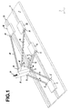
- the devices shown schematically in Figures 1 and 2 are simplified devices, in which the number structural elements is reduced.
- the workspace that the terminal element can browse is not that big, at equality of other dimensions than what the Figure 3 device, for example, but the reduction in weight of the moving parts obtained by simplifying the structure, opens up specific employment opportunities for them, for example for applications where accuracy is paramount.
- a prismatic guide 2 straight and to a degree of freedom in translation, defining a direction which, by convention, is called direction x.
- motorized slides 3 and 4 are mounted on guide 2 of way that the movement control of these sliders allows them to be moved independently of each other in the direction x.
- Each of slides 3 and 4 has two ends, that is to say on a line which remains substantially perpendicular to x, two ball joints 5, respectively 6, which serve as support and articulation on the slide to pairs of rigid support bars 7, respectively 8, the upper ends of each of these pairs of bars of support in turn carrying two pairs of ball joints 9, respectively 10, articulating a nacelle 11 on the two legs formed by pairs of bars 7 and 8.
- the nacelle 11 is here represented by a block in the form of rectangular parallelepiped whose lower surface rectangular carries at each of its four angles one of the ball joints 9 or 10.
- Ball joints 9 or 10 can also be find anywhere in the volume nacelle 11 parallelepiped, provided, however that the two ball joints 9, respectively 10, of a pair are placed on a straight line parallel to the axis of rotation of the nacelle 11.
- On the nacelle 11 is rigidly fixed the body a terminal element (active or passive member) 21, for example a spindle carrying a cutter or other rotary tool, of which the axis of rotation can be arbitrarily oriented relative to in the basket.
- the device further comprises an auxiliary structure which controls the two residual degrees of freedom of the nacelle and therefore of the terminal element 21.
- This structure comprises on the one hand a pivot bar 14, intended for the control of the pivoting of the nacelle, and on the other hand a side bar 18, intended for controlling the degree of freedom of the nacelle in the y direction.
- the pivot bar 14 is articulated at one of its ends, via a ball joint 13, on a motorized slide 12, arranged to move on the guide prismatic 2, outside the grip of slides 3 and 4 control legs 7 and 8. It is articulated to its other end, via a ball joint 15, at the end an element 20 integral with the nacelle 11 and projecting laterally with respect to it.
- This provision allows maintain a very wide angle throughout the working field close to normal between the direction of the acting force on the terminal element for its pivoting under the action of the slide 12 and the right passing through the ball joints 10 and 15, property which will be designated later in this description by "pursuit of angular rigidity" of the swivel control, and which allows to reach significantly higher racing performance angular and of rigidity than those of the proposed devices so far.
- the provision described does not control the degree of freedom in the direction y of the device.
- This control is obtained by the bar lateral 18 which is articulated, at one of its ends, by via a ball joint 17, on a motorized slide 16, arranged to move on a prismatic guide 23, straight and with a degree of freedom in translation, parallel the guide 2 is also arranged in the base surface 1.
- the bar 18 is articulated at its other end, by via a ball joint 19, on the element 20. It is advisable to clarify that the ball joint 19 does not necessarily have to be mounted on element 20, but it could also be mounted on the nacelle 11 or on the terminal element 21.
- the slides can be designed as carriages driven by a motor whose organ drive meshes in a fixed rack, or by a ball screw, or a chain traction system or by a linear or other motor.
- Ball joints 5, 6, 9, 10, 13, 15, 17 and 19 ensure the articulation of a bar on the part which the door or the one she wears around any axis with an amplitude which depends on its construction. They can be of the gimbal type.
- the device of Figure 1 can be built to achieve and control positioning exact of the terminal element 21 not only in any point of a predetermined xyz workspace but still with a predetermined orientation of the axis of the terminal element about a pivot axis parallel to the y direction.
- the whole nacelle 11 - terminal element 21 is supported by the legs 7, 8 and for each position of the slides 3, 4, it two degrees of freedom remain: a displacement in an arc in the yz plane by deformation of the parallelograms 7, 8 and a rotation around a virtual axis parallel to the direction there.
- these two degrees of freedom are exactly controlled by the relative positions of the slides 12 and 16 on the prismatic guides 2, 23.
- the positions of these guides prismatic and the lengths of the pivot bars 14 and lateral 18 fully determine the workspace the terminal element 21 can reach.
- the guides 2 and 23 are parallel guides, but they can of course also be arranged in any direction of space or be curved.
- slides 3, 4 and 12 could move on separate guides.
- the straight prismatic guides could be replaced by pivoting levers with one degree of freedom: so, for example, slides 3 and 4 could be replaced by two levers with pivot axes parallel to y.
- Slides 12 and 16 can be replaced by levers with pivot axes positioned so any.
- the levers can be motorized or not.
- Figure 10 illustrates, by way of example, a second variant of the first embodiment shown in Figure 1 and in which the slides 3 and 4 are replaced by 3 'and 4' levers, sliders 12 and 16 being replaced by levers 12 'and 16'.
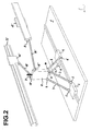
- FIG. 2 shows a simplified variant of the auxiliary structure of the first embodiment.
- the motorized sliders 12 'and 16' of pivot bars 14 'and lateral 18' are mounted on two prismatic guides 22 and 23 'rectilinear to a degree of freedom, parallel to guide 2, i.e. oriented along the direction x, but raised so as to be at a certain distance in the direction of the z direction from in the plane of the base 1.
- These guides 22 and 23 ' are located on either side of the vertical plane xz of symmetry of the device.
- the element 20 is not necessary to obtain a pursuit of satisfactory angular stiffness and the ball joints 15 'and 19' can be mounted directly on the nacelle 11, preferably at either end of its surface higher. It will be noted that, in this variant, the bars 14 ' and 18 'are both involved in the swivel control and control of the degree of freedom in the y direction.
- FIG. 3 a second form of the device of the invention, with the same schematic as in Figure 1.
- the two parallel and oriented prismatic guides 2 and 23 in direction x the two slides 3 and 4 which play the same role as the elements of the same designation of the first form of execution, i.e. support by means of ball joints 5 and 6 of two pairs of support bars 7 and 8, each pair carrying two ball joints 9 or 10 linked as in the FIG. 1 to the nacelle 11 secured to the terminal element 21.
- the arrangement of the nacelle support "legs" being the same as in the first embodiment, the structure auxiliary which controls the two residual degrees of freedom of the terminal element 21 differs therefrom.
- the auxiliary structure has a pivot bar 14 and a side bar 18 mounted on slides 12 and 16 moving respectively on the prismatic guide 2 and on a guide prismatic 23 identically to what has been described in look at Figure 1.
- the device of Figure 3 comprises three rigid members: a pivoting plate 29, the control bar 14, and a control bar 27.
- the pivot plate 29 is articulated on the nacelle 11 by a axis 30 parallel to direction y. It is represented by a trapezoidal element and its front edge carries the two ball joints 15 and 19 for the articulation of the bars 14 and 18 and a third ball joint 28 which is articulated on the bar of control 27.
- the other end of the control bar 27 is mounted, via a ball joint 26, on a part 25 of the slide 3.
- the location of the ball 26 on the slide 3 is not decisive.
- the ball 26 could also be more forward or further back, as well as more high or lower.
- the centers of the ball joints 28 and 15 can be positioned anywhere in the volume of the pivot plate 29 but they should not be located on axis 30.
- Sidebar 18 does not have to be connected to the pivot plate, but can be connected to any other element of the kinematic device, so that a displacement of the latter in the direction y is obtained.
- the terminal element is fixed if the slides 3, 4, 12 and 16 are themselves fixed on their prismatic guide respective, and any movement is rotated around a axis parallel to 30 either in translation in the space of work can be controlled by acting on the motors which drive the said slides.
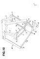
- Figure 4 illustrates a variant without lateral movement of the second embodiment of the device of the invention.
- the base 1 here carries a single prismatic guide 2 on which are mounted the three slides 3, 4 and 12.
- two bars from one of the pairs of support bars 7 or 8 must be rigidly connected, which amounts to replace the pair of bars in at least one of the legs with a simple element with at least one ball joint on one of the legs are replaced by pivots with axes parallel to axis 30.
- Other arrangements with two pivots are also conceivable.
- the auxiliary structure which ensures the pivoting of the nacelle 11 connected integrally to the terminal element 21 around joints 9 and 10, comprises the axis 30 and the plate pivot 29 on the front edge of which are mounted the intermediate joints 28 and 15 connecting to the plate 29 the control bar 27 and the control bar pivoting 14, itself resting on the articulation 13 of the slide 12. Joints 9 and 10 could be combined so as to have their axes combined. So does even joints 15 and 28.
- FIG. 4 the scale of the angular travel that the auxiliary structure can impose to the nacelle 11 by a simple displacement of the slide 12 between the two extreme positions 12a and 12b.
- the positions control bar 27 are marked 27a and 27b.
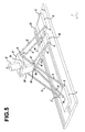
- the third embodiment differs from that of FIG. 3 on the one hand by the arrangement of the pivot plate 29 'which causes, for a movement of the slide 12 in the same direction, a reverse movement of the nacelle in comparison with the movement of the nacelle of the device of FIG. 3. In in certain cases, this provision makes it possible to obtain particularly advantageous operating conditions.
- the terminal element 21 is here also rigidly secured of the nacelle 11, and all the joints are of the patella, except for the articulation (simple) 30 of the pivot plate 29 'on the nacelle, which is oriented in the direction y.
- the base plate 1 here also carries the two guides parallel prismatic 2 and 23.
- the prismatic guide 2 On the prismatic guide 2 are mounted the two slides 3 and 4, which play exactly the same role as slides 3 and 4 in figure 3. They bear by means of ball joints 5, respectively 6, pairs of support bars 7, respectively 8, forming two parallelograms and defining two support legs the nacelle 11.
- the location of the ball joints on the pivot plate 29 ' is not decisive, on the sole condition that they are not located on axis 30.
- the slide 12 is mounted in this case on the guide 2 so as to move between the slides 3 and 4, the arrangement of the pivot plate 29 'and the bar pivot 14, side bar 18 and bar control 27 being chosen so that the pivoting plate can pivot between the support bars 7.
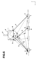
- FIG. 6 A variant without lateral movement of the device of the Figure 5 is shown in Figure 6.
- This device can actually be seen as the reverse device of that shown in Figure 4, in that the only difference compared to the device with three degrees of freedom represented in Figure 4 resides in the position of the joint 30 on the nacelle relative to the pivot joints 9 and 10.
- the ball 15 could also be fixed on bar 27, provided that it is not confused with ball 26, or ball 28 could be attached to the bar 14, provided that it is not confused with the ball joint 13.
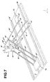
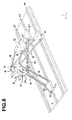
- FIGS 7 and 8 show two examples of a fourth form of the device of the invention, in which the movement of the terminal element 21 is not rigidly integral with that of the nacelle designated by 50.
- the structure support and displacement of the nacelle is, in these two examples, a structure of the type described in EP 0250470 and US Patents 4,976,582, i.e.
- the three legs of the structure described are each formed by a pair of support bars 46, 47, 48 articulated by ball joints on the slide which door and on one side of the basket. So we have a structure of three deformable parallelograms which hold the carrycot parallel to the base and allows to control movements in translation of the gondola in all the planned working space.
- the terminal element 21 is here mounted in articulation on the nacelle so as to be able to pivot about an axis 51 secured to the nacelle.
- the auxiliary structure which makes it possible to control a controlled pivoting of the terminal element 21 around the axis 51 includes a pivot plate 29 "mounted at one of its pivoting ends on the terminal element 21 around a axis 30 ', and cooperating with a pivot bar 14 "and a 27 "control bar.
- the 14" pivot bar is mounted articulated at one of its ends on a slide motorized 12 "which can move along a guide prismatic 43 and articulated at its other end on the swivel plate 29 ".
- Control bar 27" is mounted articulated at one of its 26 “ends on the slide 40 and articulated at its other end on the plate 50, at a location not confused with the axis 30 '.
- the 26 "joint could also be mounted on the nacelle 50 at a location not confused with axis 51.
- the slides 40, 41 and 42 could be replaced by pivoting levers, the pivot axes of these levers in front here to be respectively parallel to the axis passing through the centers of the ball joints mounted at the base of the legs 46, 47 and 48.
- the 12 "slide it could be replaced by a lever pivoting around an axis positioned so any.
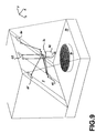
- Figure 9 shows an example of application of the device according to the invention to a machine tool.
- the form of execution chosen to show this application is similar to that of figure 3, to except that slides 60 and 61, corresponding to the slides 12 and 16 of the device of the FIG. 2 are guided in separate prismatic guides, parallel to the x direction. Slides 48 and 49 correspond to the slides 3 and 4 of the device in Figure 3.
- Base 1 is an inclined plate, for example at 45 ° above work table 89, fitted with a turntable 90 of axis, for example vertical. This is intended to receive a part on which the tool of the terminal element 92 integral with the nacelle 91 can execute different machining operations. It is also possible that the terminal element 92 is equipped with a coin carrier, driven or not, and that the turntable is replaced by one or more motorized or passive tools or a combination of both, and machining is done by moving the part in front of the tools.
- each single bar such as 14, 18, 27, a second bar which is parallel to it and which works identically.
- This mode of operation improves the stability of the device and to increase its rigidity.
- the negative effects of hyper-guidance thus generated can be eliminated to a great extent by known solutions, such as a high achievement precision or the introduction of a balancing lever.
Landscapes
- Engineering & Computer Science (AREA)
- Mechanical Engineering (AREA)
- Robotics (AREA)
- Manipulator (AREA)
- Machine Tool Units (AREA)
- Transmission Devices (AREA)
- Pivots And Pivotal Connections (AREA)
- Prostheses (AREA)
- Organic Low-Molecular-Weight Compounds And Preparation Thereof (AREA)
Abstract
Description
La présente invention appartient au domaine technique des dispositifs cinématiques de support et de déplacement qui permettent de commander de manière programmable et avec une précision élevée des déplacements en translation et/ou en rotation d'un élément terminal dans un champ de travail prédéterminé.The present invention belongs to the technical field of kinematic support and displacement devices which allow to control in a programmable way and with a high precision of displacements in translation and / or in rotation of a terminal element in a working field predetermined.
L'élément terminal peut être un outil d'usinage (broche, laser, jet d'eau, électroérosion, etc.) ou un porteur de pièces dans le cas où le dispositif est incorporé à un centre d'usinage, par exemple, ou un instrument de préhension, un outil de montage, un capteur de mesure, un interface utilisateur pour joystick à retour de forces, une antenne, un porte-caméra, etc., dans le cas de machines de transfert, de robots de montage, de machines d'emballage, d'instruments de mesure, d'instruments médicaux, etc., soit tout dispositif où un positionnement ou déplacement de haute précision et/ou une dynamique élevée est nécessaire.The terminal element can be a machining tool (spindle, laser, water jet, EDM, etc.) or a carrier parts in case the device is incorporated in a center machining, for example, or a gripping instrument, a mounting tool, measurement sensor, interface user for force feedback joystick, antenna, camera holder, etc., in the case of transfer machines, assembly robots, packaging machines, instruments medical devices, etc., or any device where high precision positioning or displacement and / or high dynamics is required.
Dans ce domaine, il existe de nombreuses applications nécessitant un préhenseur dont l'orientation soit contrôlable autour d'un axe parallèle à la base. C'est le cas, par exemple, pour la production par usinage de pièces complexes ou pour le polissage de pièces de haute qualité esthétique.There are many applications in this area requiring a gripper whose orientation is controllable around an axis parallel to the base. This is the case, for example, for the production by machining of complex parts or for polishing parts of high aesthetic quality.
En particulier, pour la production à haute cadence de petites pièces complexes, il est nécessaire de disposer de machines qui non seulement sont capables de hautes vitesses d'usinage, mais également de changements d'outils très rapides de façon à minimiser le temps copeaux à copeaux.In particular, for high speed production of small complex parts, it is necessary to have machines that not only are capable of high speeds machining, but also very rapid tool changes to minimize chip-to-chip time.
Par leur dynamique élevée (faible masse mobile et raideur élevée), les machines-outils à cinématique parallèle peuvent répondre favorablement à ces deux contraintes. By their high dynamics (low mobile mass and stiffness high), machine tools with parallel kinematics can respond favorably to these two constraints.
Cependant, les principaux défauts des robots et machines-outils parallèles existant sur le marché résident dans leur volume de travail relativement faible et une mobilité angulaire très limitée.However, the main shortcomings of robots and machine tools parallels existing in the market reside in their relatively low work volume and mobility very limited angularity.
Une structure très performante, qui s'applique plus spécifiquement à la commande du déplacement d'un élément terminal, comme par exemple un organe de préhension, est décrite dans les brevets européen EP 0250470 et américain US 4,976,582. Dans cette structure, la commande des trois degrés de liberté de base s'effectue en parallèle à partir d'actionneurs disposés sur un support fixe, en conservant le parallélisme de l'élément mobile par rapport au support fixe. Compte tenu de sa dynamique élevée et sa mobilité de trois translations dans l'espace, une telle structure est particulièrement bien adaptée pour le transfert de pièces légères à des cadences très élevées (plus de trois transferts par seconde). L'originalité de cette structure réside dans le blocage de tous les mouvements d'orientations du préhenseur par la disposition cinématique. En revanche, un tel dispositif ne permet pas de répondre tel quel aux applications pour lesquelles une ou plusieurs rotations sont requises.A very efficient structure, which applies more specifically to control the movement of an element terminal, such as a gripper, is described in European patents EP 0250470 and American US 4976582. In this structure, the control of the three degrees basic freedom is done in parallel from actuators arranged on a fixed support, keeping the parallelism of the movable element relative to the fixed support. Given its high dynamics and its mobility of three translations in space, such a structure is particularly well suited for transferring parts light at very high rates (more than three transfers per second). The originality of this structure lies in the blocking of all gripper orientation movements by the kinematic arrangement. However, such a device does not allow to respond as is to applications for which one or more rotations are required.
On connaít d'autre part les publications de demandes internationales WO 98/51443 et WO 99/32256 qui concernent la commande à cinématique parallèle d'outils tels que des fraises dans des machines-outils destinées à la fabrication de pièces délicates, notamment des aubes de turbines. Toutefois, les dispositifs décrits dans ces documents ne permettent d'effectuer que des mouvements angulaires peu importants de l'outil (d'environ ± 30°) si l'on veut conserver une bonne rigidité de la structure.We also know the publications of requests WO 98/51443 and WO 99/32256 which concern the parallel kinematic control of tools such as milling cutters in machine tools for the production of parts delicate, especially turbine blades. However, devices described in these documents do not allow to perform only small angular movements of the tool (about ± 30 °) if you want to keep a good rigidity of the structure.
Le but de la présente invention est de proposer un dispositif à cinématique parallèle qui réponde mieux et de façon plus globale aux besoins indiqués ci-dessus que les dispositifs connus et qui offre en particulier une rapidité et une précision de travail aussi grandes que possible tout en permettant de programmer des déplacements de l'élément terminal dans un champ de travail ayant un volume aussi grand que possible et assurant un comportement homogène dans ce volume de travail.The purpose of the present invention is to provide a parallel kinematic device that responds better and more comprehensively to the needs indicated above than the known devices and which in particular offers speed and working precision as high as possible while allowing to program element movements terminal in a work area with such a large volume as possible and ensuring consistent behavior in this volume of work.
Pour cela le dispositif selon la présente invention présente les caractéristiques définies selon les revendications annexées, dont le contenu doit être considéré comme faisant partie intégrante de la présente description.For this, the device according to the present invention has the characteristics defined according to appended claims, the content of which must be considered as part of this description.
On va décrire ci-après à titre d'exemples diverses formes
d'exécution du dispositif selon l'invention en se référant au
dessin schématique annexé dans lequel :
Dans le cadre de la présente description, on entend par "articulation utile" une articulation nécessaire pour le fonctionnement du dispositif auquel elle est rattachée, par opposition à des articulations qui autorisent des mobilités internes, comme par exemple dans le cas d'une barre munie de deux rotules à ses extrémités et qui a la possibilité de tourner sur elle-même, ce qui n'apporte aucune fonctionnalité.In the context of the present description, the term “ "useful joint" a joint necessary for the operation of the device to which it is attached, by opposition to joints that allow mobility internal, as for example in the case of a bar provided with two ball joints at its ends and which has the possibility of turn on itself, which does not provide any functionality.
Les figures représentent des dispositifs de support et de déplacement schématisés et susceptibles d'être appliqués soit à une machine-outil, un instrument ou un robot, soit à un autre type de machine de travail, comme par exemple une machine de montage. Dans le cas d'une machine de transfert de pièces, l'élément terminal peut être une pince, ou une ventouse, ou tout autre type d'organe de préhension. Dans le cas d'une machine-outil, cet élément terminal peut être soit une broche portant une fraise, une meule de rectifiage, une mèche de perçage, un porte-pièce, etc., soit un dispositif de jet d'eau, de découpe laser, d'électroérosion, d'ébavurage, de sablage, de peinture, de polissage, etc.. La machine peut être équipée de préhenseurs et d'outils d'usinage embarqués sur l'élément terminal, par exemple montés sur une tête revolver, ou associés à un changeur d'outils actif ou passif (soit un stock d'outils et/ou de porte-pièces).The figures represent support and displacement schematized and likely to be applied either machine tool, instrument, or robot, or other type of work machine, such as a assembly machine. In the case of a transfer machine parts, the terminal element can be a clamp, or a suction cup, or any other type of grip. In the in the case of a machine tool, this terminal element can be either a spindle carrying a cutter, a grinding wheel, a drill bit, workpiece holder, etc. water jet, laser cutting, EDM, deburring, sandblasting, painting, polishing, etc. The machine can be equipped with grippers and machining tools on board the terminal element, for example mounted on a revolver head, or associated with an active or passive tool changer (i.e. a stock of tools and / or workpiece holders).
Dans les formes d'exécution décrites ci-après, pour une meilleure compréhension des figures, l'élément terminal est symbolisé par un corps de moteur qui est associé de manière rigide à une pièce rigide appelée nacelle, celle-ci faisant partie de la structure de support et de déplacement. Cependant on rencontrera des cas, comme on le verra plus loin où l'élément terminal est monté sur la nacelle par un dispositif de pivotement autour d'un axe lié à la nacelle.In the embodiments described below, for a better understanding of the figures, the terminal element is symbolized by an engine body which is associated in a way rigid to a rigid part called a nacelle, the latter making part of the support and displacement structure. However we will encounter cases, as we will see below where the terminal element is mounted on the nacelle by a device pivot around an axis linked to the nacelle.
Les dispositifs décrits comportent dans chaque cas une
base de référence 1 qui dans la plupart des cas reste fixe.
Celle-ci sera en général matérialisée par une ou plusieurs
surfaces planes reliée(s) au socle de la machine, mais bien
entendu cette ou ces surfaces de base pourraient aussi être
incurvées. Il est essentiel cependant pour la cohérence de la
description qu'elles définissent un référentiel cartésien, à
partir duquel les axes x,y,z de l'espace de travail soient
déterminés. Par la suite on considéra que les axes x et y de
ce référentiel cartésien sont définis dans le plan de la base
du dispositif, et que la direction y est parallèle à l'axe de
rotation de la nacelle.The devices described include in each case a
Les dispositifs représentés schématiquement aux figures 1 et 2 sont des dispositifs simplifiés, dans lesquels le nombre des éléments de structure est réduit. L'espace de travail que l'élément terminal peut parcourir n'est pas si grand, à égalité des autres dimensions que ce que permet d'atteindre le dispositif de la figure 3, par exemple, mais la réduction de poids des éléments mobiles obtenue par la simplification de la structure, leur ouvre des possibilités d'emploi spécifiques, par exemple pour des applications où la précision est primordiale.The devices shown schematically in Figures 1 and 2 are simplified devices, in which the number structural elements is reduced. The workspace that the terminal element can browse is not that big, at equality of other dimensions than what the Figure 3 device, for example, but the reduction in weight of the moving parts obtained by simplifying the structure, opens up specific employment opportunities for them, for example for applications where accuracy is paramount.
Dans la surface de base plane 1 du dispositif représenté
à la figure 1 est aménagé un guidage prismatique 2, rectiligne
et à un degré de liberté en translation, définissant une
direction qui, par convention, est appelée direction x. Deux
coulisseaux motorisés 3 et 4 sont montés sur le guidage 2 de
manière que la commande du mouvement de ces coulisseaux
permette de les déplacer indépendamment l'un de l'autre dans
la direction x. Chacun des coulisseaux 3 et 4 porte à ses deux
extrémités, c'est-à-dire sur une ligne qui reste sensiblement
perpendiculaire à x, deux rotules 5, respectivement 6, qui
servent d'appui et d'articulation sur le coulisseau à des
paires de barres de support rigides 7, respectivement 8, les
extrémités supérieures de chacune de ces paires de barres de
support portant à leur tour deux paires de rotules 9,
respectivement 10, articulant une nacelle 11 sur les deux
jambes formées par les paires de barres 7 et 8. Les deux
barres de chaque paires 7 ou 8 sont de préférence parallèles.
La nacelle 11 est ici figurée par un bloc en forme de
parallélépipède rectangle dont la surface inférieure
rectangulaire porte à chacun de ses quatre angles une des
rotules 9 ou 10. Les rotules 9 ou 10 peuvent également se
trouver à n'importe quel endroit dans le volume
parallélépipédique de la nacelle 11, à la condition toutefois
que les deux rotules 9, respectivement 10, d'une paire soient
placées sur une droite parallèle à l'axe de rotation de la
nacelle 11. Sur la nacelle 11 est rigidement fixé le corps
d'un élément terminal (organe actif ou passif) 21, par exemple
une broche portant une fraise ou autre outil rotatif, dont
l'axe de rotation peut être orienté arbitrairement par rapport
à la nacelle.In the
Le dispositif comporte en outre une structure auxiliaire
qui contrôle les deux degrés de liberté résiduels de la
nacelle et donc de l'élément terminal 21. Cette structure
comprend d'une part une barre de pivotement 14, destinée à la
commande du pivotement de la nacelle, et d'autre part une
barre latérale 18, destinée au contrôle du degré de liberté de
la nacelle dans le sens y.The device further comprises an auxiliary structure
which controls the two residual degrees of freedom of the
nacelle and therefore of the
La barre de pivotement 14 est articulée, à l'une de ses
extrémités, par l'intermédiaire d'une rotule 13, sur un
coulisseau motorisé 12, agencé pour se déplacer sur le guidage
prismatique 2, en dehors de l'emprise des coulisseaux 3 et 4
de commande des jambes 7 et 8. Elle est articulée à son autre
extrémité, par l'intermédiaire d'une rotule 15, à l'extrémité
d'un élément 20 solidaire de la nacelle 11 et en saillie
latéralement par rapport à celle-ci. Cette disposition permet
de conserver dans tout le champ de travail un angle très
voisin de la normale entre la direction de la force agissant
sur l'élément terminal pour son pivotement sous l'action du
coulisseau 12 et la droite passant par les rotules 10 et 15,
propriété que l'on désignera dans la suite de cette
description par "poursuite de rigidité angulaire" de la
commande du pivotement, et qui permet d'atteindre des
performances nettement supérieures en termes de courses
angulaires et de rigidité que celles des dispositifs proposés
jusqu'ici.The
Du fait des liaisons par rotules et malgré le fait que la
rotule 13 est placée sur un angle du coulisseau 12 placé lui-même
en position symétrique par rapport à la glissière 2, la
disposition décrite ne contrôle pas le degré de liberté dans
le sens y du dispositif. Ce contrôle est obtenu par la barre
latérale 18 qui est articulée, à l'une de ses extrémités, par
l'intermédiaire d'une rotule 17, sur un coulisseau motorisé
16, agencé pour se déplacer sur un guidage prismatique 23,
rectiligne et à un degré de liberté en translation, parallèle
au guidage 2 est également disposé dans la surface de base 1.
La barre 18 est articulée à son autre extrémité, par
l'intermédiaire d'une rotule 19, sur l'élément 20. Il convient
de préciser que la rotule 19 ne doit pas impérativement être
montée sur l'élément 20, mais elle pourrait également être
montée sur la nacelle 11 ou sur l'élément terminal 21.Because of the ball joints and despite the fact that the
Cette disposition est suffisante pour contrôler
entièrement le positionnement de l'élément terminal 21 dans
tout l'espace de travail.This provision is sufficient to control
fully positioning the
On comprend que les coulisseaux peuvent être conçus comme
des chariots entraínés par un moteur dont l'organe
d'entraínement engrène dans une crémaillère fixe, ou par une
vis à bille, ou un système de traction à chaíne ou encore par
un moteur linéaire ou autre. Les rotule 5, 6, 9, 10, 13, 15,
17 et 19 assurent l'articulation d'une barre sur la partie qui
la porte ou sur celle qu'elle porte autour de n'importe quel
axe avec une amplitude qui dépend de sa construction. Elles
peuvent être du type cardan.It is understood that the slides can be designed as
carriages driven by a motor whose organ
drive meshes in a fixed rack, or by a
ball screw, or a chain traction system or by
a linear or other motor.
On comprend que le dispositif de la figure 1 peut être
construit de manière à réaliser et contrôler le positionnement
exact de l'élément terminal 21 non seulement en n'importe quel
point d'un espace de travail xyz prédéterminé mais encore avec
une orientation prédéterminée de l'axe de l'élément terminal
autour d'un axe de pivotement parallèle à la direction y. En
l'absence de la structure auxiliaire 12 à 20, l'ensemble
nacelle 11 - élément terminal 21 est supporté par les jambes
7, 8 et pour chaque position des coulisseaux 3, 4, il lui
reste deux degrés de liberté: un déplacement en arc de cercle
dans le plan yz par déformation des parallélogrammes 7, 8 et
une rotation autour d'un axe virtuel parallèle à la direction
y. Or ces deux degrés de liberté sont exactement contrôlés par
les positions relatives des coulisseaux 12 et 16 sur les
guidages prismatiques 2, 23. Les positions de ces guidages
prismatiques et les longueurs des barres de pivotement 14 et
latérale 18 déterminent entièrement l'espace de travail que
l'élément terminal 21 peut atteindre.We understand that the device of Figure 1 can be
built to achieve and control positioning
exact of the
Dans l'exemple de la figure 1, les guidages 2 et 23 sont
des guidage parallèles, mais ils peuvent bien entendu
également être disposés dans n'importe quelle direction de
l'espace ou être courbes. De même, les coulisseaux 3, 4 et 12
pourraient se déplacer sur des guidages séparés. D'autre part,
les guidages prismatiques rectilignes pourraient être
remplacés par des leviers pivotants à un degré de liberté:
ainsi, par exemple, les coulisseaux 3 et 4 pourraient être
remplacés par deux leviers à axes de pivotement parallèle à y.
Les coulisseaux 12 et 16 peuvent, quant à eux, être remplacés
par des leviers à axes de pivotement positionnés de façon
quelconque. Les leviers peuvent être motorisés ou non. Les
remarques qui précèdent s'appliquent également à toutes les
autres formes d'exécution et variantes que l'on va décrire ci-après. In the example of FIG. 1, the
La figure 10 illustre, à titre d'exemple, une seconde
variante de la première forme d'exécution représentée à la
figure 1 et dans laquelle les coulisseaux 3 et 4 sont
remplacés par des leviers 3' et 4', les coulisseaux 12 et 16
étant remplacés par des leviers 12' et 16'.Figure 10 illustrates, by way of example, a second
variant of the first embodiment shown in
Figure 1 and in which the
On a représenté à la figure 2 une variante simplifiée de
la structure auxiliaire de la première forme d'exécution. Dans
cette variante, les coulisseaux motorisés 12' et 16' des
barres de pivotement 14' et latérale 18' sont montées sur deux
guidages prismatiques 22 et 23' rectilignes à un degré de
liberté, parallèles au guidage 2, c'est-à-dire orientés selon
la direction x, mais surélevés de manière à se trouver à une
certaine distance dans le sens de la direction z par rapport
au plan de la base 1. Ces guidages 22 et 23' sont situés de
part et d'autre du plan vertical xz de symétrie du dispositif.
Compte tenu de la disposition des guidages 22 et 23', la
présence de l'élément 20 n'est pas nécessaire pour obtenir une
poursuite de rigidité angulaire satisfaisante et les rotules
15' et 19' peuvent être montées directement sur la nacelle 11,
de préférence à l'une ou l'autre des extrémités de sa surface
supérieure. On notera que, dans cette variante, les barres 14'
et 18' interviennent toutes les deux à la fois dans la
commande du pivotement et dans celle du contrôle du degré de
liberté dans la direction y.FIG. 2 shows a simplified variant of
the auxiliary structure of the first embodiment. In
this variant, the motorized sliders 12 'and 16' of
pivot bars 14 'and lateral 18' are mounted on two
On a représenté à la figure 3 une deuxième forme
d'exécution du dispositif de l'invention, avec le même
schématisme qu'à la figure 1. On reconnaít sur cette figure
une bonne partie des éléments déjà décrits et ils sont
désignés par les mêmes signes de référence. On retrouve ainsi
les deux guidages prismatiques 2 et 23 parallèles et orientées
selon la direction x, les deux coulisseaux 3 et 4 qui jouent
le même rôle que les éléments de même désignation de la
première forme d'exécution, c'est-à-dire support au moyen de
rotules 5 et 6 de deux paires de barres de support 7 et 8,
chaque paire portant deux rotules 9 ou 10 liées comme dans la
figure 1 à la nacelle 11 solidaire de l'élément terminal 21.
La disposition des "jambes" de support de la nacelle étant la
même que dans la première forme d'exécution, la structure
auxiliaire qui contrôle les deux degrés de liberté résiduels
de l'élément terminal 21 en diffère.There is shown in Figure 3 a second form
of the device of the invention, with the same
schematic as in Figure 1. We recognize in this figure
a good part of the elements already described and they are
designated by the same reference signs. We thus find
the two parallel and oriented
Comme dans le cas de la figure 1, la structure auxiliaire
comporte une barre de pivotement 14 et une barre latérale 18
montées sur des coulisseaux 12 et 16 se déplaçant
respectivement sur le guidage prismatique 2 et sur un guidage
prismatique 23 de façon identique à ce qui à été décrit en
regard de figure 1. En revanche, pour assurer le contrôle du
pivotement de la nacelle, le dispositif de la figure 3
comporte trois organes rigides : une plaque de pivotement 29,
la barre de commande 14, et une barre de contrôle 27. La
plaque de pivotement 29 est articulée sur la nacelle 11 par un
axe 30 parallèle à la direction y. Elle est représentée par un
élément de forme trapézoïdale et son arête antérieure porte
les deux rotules 15 et 19 pour l'articulation des barres 14 et
18 et une troisième rotule 28 qui s'articule sur la barre de
contrôle 27. L'autre extrémité de la barre de contrôle 27 est
montée, par l'intermédiaire d'une rotule 26, sur une partie 25
du coulisseau 3. L'emplacement de la rotule 26 sur le
coulisseau 3 n'est pas déterminant. La rotule 26 pourrait
aussi être plus en avant ou plus en arrière, ainsi que plus
haut ou plus bas. De même, les centres des rotules 28 et 15
peuvent être positionnés n'importe où dans le volume de la
plaque de pivotement 29, mais ils ne doivent pas être situés
sur l'axe 30.As in the case of Figure 1, the auxiliary structure
has a
La barre latérale 18 ne doit pas nécessairement être
reliée à la plaque de pivotement, mais peut être reliée à tout
autre élément du dispositif cinématique, de manière qu'un
déplacement de cette dernière dans la direction y soit obtenu.
L'élément terminal est fixe si les coulisseaux 3, 4, 12
et 16 sont eux-mêmes fixes sur leur guidage prismatique
respectif, et tout déplacement soit en rotation autour d'un
axe parallèle à 30 soit en translation dans l'espace de
travail peut être commandé en agissant sur les moteurs qui
entraínent les dits coulisseaux.The terminal element is fixed if the
La figure 4 illustre une variante sans mouvement latéral
de la deuxième forme d'exécution du dispositif de l'invention.
On retrouve la même structure de support avec deux jambes
montées sur deux coulisseaux et la même structure auxiliaire
de pivotement avec une articulation intermédiaire, que dans
les formes d'exécution précédentes. Du fait de l'absence du
coulisseau 16 et de la barre latérale 18, les déplacements
dans le sens y seront obtenus ici par un déplacement relatif
entre le dispositif et les moyens de maintien de l'objet sur
lequel l'élément terminal agit. On parle aussi d'un dispositif
à main gauche et main droite.Figure 4 illustrates a variant without lateral movement
of the second embodiment of the device of the invention.
We find the same support structure with two legs
mounted on two slides and the same auxiliary structure
pivoting with an intermediate joint, only in
previous embodiments. Due to the absence of the
La base 1 porte ici un seul guidage prismatique 2 sur
lequel sont montés les trois coulisseaux 3, 4 et 12. Pour
éviter tout mouvement latéral incontrôlé de la nacelle, les
deux barres d'une des paires de barres de support 7 ou 8
doivent être reliées de façon rigide, ce qui revient à
remplacer dans au moins une des jambes la paire de barres par
un élément simple dont au moins sur une des jambes les rotules
sont remplacées par des pivots à axes parallèles à l'axe 30.
D'autres dispositions à deux pivots sont également
envisageables.The
La structure auxiliaire, qui assure le pivotement de la
nacelle 11 liée solidairement à l'élément terminal 21 autour
des articulations 9 et 10, comporte l'axe 30 et la plaque de
pivotement 29 sur le bord antérieur de laquelle sont montées
les articulations intermédiaires 28 et 15 reliant à la plaque
29 la barre de contrôle 27 et la barre de commande de
pivotement 14, s'appuyant elle-même sur l'articulation 13 du
coulisseau 12. Les articulations 9 et 10 pourraient être
combinées de façon à avoir leurs axes confondus. Il en va de
même des articulations 15 et 28. The auxiliary structure, which ensures the pivoting of the
A la figure 4 on voit encore en pointillé l'ampleur du
débattement angulaire que la structure auxiliaire peut imposer
à la nacelle 11 par un simple déplacement du coulisseau 12
entre les deux positions extrêmes 12a et 12b. Les positions
correspondantes de la barre de contrôle 27 sont notées 27a et
27b.In FIG. 4, the scale of the
angular travel that the auxiliary structure can impose
to the
La troisième forme d'exécution, représentée à la figure
5, diffère de celle de la figure 3 d'une part par l'agencement
de la plaque de pivotement 29' qui provoque, pour un
déplacement du coulisseau 12 dans la même direction, un
mouvement inversé de la nacelle en comparaison avec le
mouvement de la nacelle du dispositif de la figure 3. Dans
certains cas, cette disposition permet d'obtenir des
conditions de fonctionnement particulièrement avantageuses.The third embodiment, shown in Figure
5, differs from that of FIG. 3 on the one hand by the arrangement
of the pivot plate 29 'which causes, for a
movement of the
L'élément terminal 21 est ici aussi rigidement solidaire
de la nacelle 11, et toutes les articulations sont du type à
rotule, à l'exception de l'articulation (simple) 30 de la
plaque de pivotement 29' sur la nacelle, qui est orientée dans
la direction y.The
La plaque de base 1 porte ici aussi les deux guidages
prismatiques parallèles 2 et 23. Sur le guidage prismatique 2
sont montés les deux coulisseaux 3 et 4, qui jouent exactement
le même rôle que les coulisseaux 3 et 4 de la figure 3. Ils
portent par l'intermédiaire de rotules 5, respectivement 6,
des couples de barres de support 7, respectivement 8, formant
deux parallélogrammes et définissant deux jambes de support de
la nacelle 11. Comme dans le cas de la figure 3, l'emplacement
des rotules sur la plaque de pivotement 29' n'est pas
déterminant, à la seule condition qu'elles ne soient pas
situées sur l'axe 30. On retrouve également une structure
auxiliaire avec deux organes rigides et une articulation
intermédiaire. Toutefois, l'ensemble est agencé de façon que
le mouvement de pivotement de la nacelle 11 s'effectue dans le
sens inverse de celui de la nacelle du dispositif représenté à
la figure 3. Le coulisseau 12 est monté dans ce cas sur le
guidage 2 de façon à se déplacer entre les coulisseaux 3 et 4,
la disposition de la plaque de pivotement 29' et de la barre
de pivotement 14, de la barre latérale 18 et de la barre de
contrôle 27 étant choisie de façon que la plaque de pivotement
puisse pivoter entre les barres de support 7.The
Une variante sans mouvement latéral du dispositif de la
figure 5 est représentée à la figure 6. Ce dispositif peut en
fait être considéré comme le dispositif inverse de celui
représenté à la figure 4, en ce sens que la seule différence
par rapport au dispositif à trois degrés de liberté représenté
à la figure 4 réside dans la position de l'articulation 30 sur
la nacelle par rapport aux articulations de pivotement 9 et
10.A variant without lateral movement of the device of the
Figure 5 is shown in Figure 6. This device can
actually be seen as the reverse device of that
shown in Figure 4, in that the only difference
compared to the device with three degrees of freedom represented
in Figure 4 resides in the position of the joint 30 on
the nacelle relative to the
Il convient de noter que dans tous les exemples illustrés
aux figures 3 à 6, la rotule 15 pourrait aussi être fixée sur
la barre 27, à condition qu'elle ne soit pas confondue avec la
rotule 26, ou la rotule 28 pourrait être fixée sur la barre
14, à condition qu'elle ne soit pas confondue avec la rotule
13.It should be noted that in all the examples illustrated
in Figures 3 to 6, the
Alors que dans tous les exemples décrits ci-dessus
l'élément terminal est rigidement solidaire de la nacelle, les
figures 7 et 8 montrent deux exemples d'une quatrième forme
d'exécution du dispositif de l'invention, dans lequel le
mouvement de l'élément terminal 21 n'est pas rigidement
solidaire de celui de la nacelle désignée par 50. La structure
de support et de déplacement de la nacelle est, dans ces deux
exemples, une structure du type de celle décrite dans les
brevets EP 0250470 et US 4,976,582, c'est-à-dire une structure
dans laquelle les trois degrés de liberté de base de la
nacelle s'effectuent en parallèle à partir de trois
coulisseaux motorisés 40, 41 et 42, se déplaçant le long de
trois guidages prismatiques parallèles 43, 44 et 45, et
actionnant chacun une jambe 46, 47 et 48 supportant la nacelle
50, de façon à conserver le parallélisme de la nacelle par
rapport à la base 1. Les trois jambes de la structure décrite
sont formées chacune par une paire de barres de support 46,
47, 48 articulées par des rotules sur le coulisseau qui les
porte et sur un côté de la nacelle. On a donc une structure de
trois parallélogrammes déformables qui maintient la nacelle
parallèle à la base et permet de commander des déplacements en
translation de la nacelle dans tout l'espace de travail prévu.
L'élément terminal 21 est ici monté en articulation sur la
nacelle de façon à pouvoir pivoter autour d'un axe 51
solidaire de la nacelle.While in all of the examples described above
the terminal element is rigidly secured to the nacelle, the
Figures 7 and 8 show two examples of a fourth form
of the device of the invention, in which the
movement of the
La structure auxiliaire qui permet de commander un
pivotement contrôlé de l'élément terminal 21 autour de l'axe
51 comprend une plaque de pivotement 29" montée à l'une de ses
extrémités en pivotement sur l'élément terminal 21 autour d'un
axe 30', et coopérant avec une barre de pivotement 14" et une
barre de contrôle 27". La barre de pivotement 14" est montée
en articulation à l'une de ses extrémité sur un coulisseau
motorisé 12" pouvant se déplacer le long d'un guidage
prismatique 43 et en articulation à son autre extrémité sur la
plaque de pivotement 29". La barre de contrôle 27" est montée
en articulation à l'une de ses extrémités 26" sur le
coulisseau 40 et en articulation à son autre extrémité sur la
plaque 50, à un endroit non confondu avec l'axe 30'. Dans une
variante, l'articulation 26" pourrait aussi être montée sur la
nacelle 50 à un endroit non confondu avec l'axe 51.The auxiliary structure which makes it possible to control a
controlled pivoting of the
Les deux variantes représentées au figures 7 et 8 se
distinguent par l'agencement de la plaque de pivotement 29"
qui provoque, pour un déplacement du coulisseau 12" dans la
même direction, des mouvements de pivotement inversés de
l'élément terminal 21.The two variants shown in Figures 7 and 8 are
distinguished by the arrangement of the
Comme dans le cas des autres modes d'exécution décrits,
les coulisseaux 40, 41 et 42 pourraient être remplacés par des
leviers pivotants, les axes de pivotement de ces leviers
devant ici être respectivement parallèles à l'axe passant par
les centres des rotules montées à la base des jambes 46, 47 et
48. Quant au coulisseau 12", il pourrait être remplacé par un
levier pivotant autour d'un axe positionné de façon
quelconque.As in the case of the other embodiments described,
the
Il convient de noter que dans les exemples illustrés aux
figures 7 et 8, la rotule 15" pourrait aussi être fixée sur la
barre 27", à condition qu'elle ne soit pas confondue avec la
rotule 26", ou la rotule 28" pourrait être fixée sur la barre
14", à condition qu'elle ne soit pas confondue avec la rotule
13".It should be noted that in the examples illustrated in
Figures 7 and 8, the
Il reste à décrire la figure 9 qui montre un exemple
d'application du dispositif selon l'invention à une machine-outil.
La forme d'exécution choisie pour montrer cette
application est semblable à celle de la figure 3, à
l'exception du fait que les coulisseaux 60 et 61,
correspondant aux coulisseaux 12 et 16 du dispositif de la
figure 2, sont guidés dans des guidages prismatiques séparés,
parallèles à la direction x. Les coulisseaux 48 et 49
correspondent quant à eux aux coulisseaux 3 et 4 du dispositif
de la figure 3.It remains to describe Figure 9 which shows an example
of application of the device according to the invention to a machine tool.
The form of execution chosen to show this
application is similar to that of figure 3, to
except that slides 60 and 61,
corresponding to the
La base 1 est une plaque inclinée, par exemple à 45° au-dessus
de la table de travail 89, munie d'un plateau tournant
90 d'axe par exemple vertical. Celui-ci est destiné à recevoir
une pièce sur laquelle l'outil de l'élément terminal 92
solidaire de la nacelle 91 pourra exécuter différentes
opérations d'usinage. Il est également envisageable que
l'élément terminal 92 soit équipé d'un porteur de pièces,
entraíné ou pas, et que le plateau tournant soit remplacé par
un ou plusieurs outils motorisés ou passifs ou une combinaison
des deux, et l'usinage est réalisé en déplaçant la pièce
devant les outils.
De façon générale, il est possible d'ajouter à chaque barre simple, comme par exemple 14, 18, 27, une deuxième barre qui lui est parallèle et qui travaille de façon identique. Ce mode de faire permet d'améliorer la stabilité du dispositif et d'augmenter sa rigidité. Les effets négatifs de l'hyperguidage ainsi généré peuvent être éliminés dans une grande mesure par des solutions connues, telles qu'une réalisation de haute précision ou l'introduction d'un levier d'équilibrage.In general, it is possible to add to each single bar, such as 14, 18, 27, a second bar which is parallel to it and which works identically. This mode of operation improves the stability of the device and to increase its rigidity. The negative effects of hyper-guidance thus generated can be eliminated to a great extent by known solutions, such as a high achievement precision or the introduction of a balancing lever.
Claims (17)
Priority Applications (16)
| Application Number | Priority Date | Filing Date | Title |
|---|---|---|---|
| EP01810193A EP1234632A1 (en) | 2001-02-23 | 2001-02-23 | Kinematic device for programmably supporting and positioning an end element in a machine or an instrument |
| CA2439881A CA2439881C (en) | 2001-02-23 | 2002-02-21 | A kinematic device for supporting and programmably moving a terminal element in a machine or an instrument |
| EA200300921A EA005147B1 (en) | 2001-02-23 | 2002-02-21 | Kinematic device for support programmable displacement of a terminal element in a machine or an instrument |
| HU0303205A HUP0303205A2 (en) | 2001-02-23 | 2002-02-21 | Kinematic device for support and programmable displacement of a terminal element in a machine or an instrument |
| PCT/CH2002/000100 WO2002066203A1 (en) | 2001-02-23 | 2002-02-21 | Kinematic device for support and programmable displacement of a terminal element in a machine or an instrument |
| PL364104A PL205720B1 (en) | 2001-02-23 | 2002-02-21 | Kinematic device for support and programmable displacement of a terminal element in a machine or an instrument |
| CNB028068300A CN100462197C (en) | 2001-02-23 | 2002-02-21 | Kinematic device for support and programmable displacement of trerminal elementin machine or instrument |
| IL15747602A IL157476A0 (en) | 2001-02-23 | 2002-02-21 | Kincmatic device for supporting and programmable displacement of a terminal element in a machine or an instrument |
| KR1020037011109A KR100882624B1 (en) | 2001-02-23 | 2002-02-21 | Kinematic device for support and programmable displacement of a terminal element in a machine or an instrument |
| CZ20032512A CZ20032512A3 (en) | 2001-02-23 | 2002-02-21 | Kinematical device for support and programmable displacement of a terminal element in a machine or an instrument |
| SK1164-2003A SK11642003A3 (en) | 2001-02-23 | 2002-02-21 | Kinematic device for support and programmable displacement of a terminal element in a machine or an instrument |
| EP02710747A EP1365887A1 (en) | 2001-02-23 | 2002-02-21 | Kinematic device for support and programmable displacement of a terminal element in a machine or an instrument |
| JP2002565749A JP4523228B2 (en) | 2001-02-23 | 2002-02-21 | Motion device for supporting and programmably driving an end element in a machine or instrument |
| IL157476A IL157476A (en) | 2001-02-23 | 2003-08-19 | Kinematic device for supporting and programmable displacement of a terminal element in a machine or an instrument |
| US10/648,730 US8303238B2 (en) | 2001-02-23 | 2003-08-22 | Kinematic device for supporting and programmably moving a terminal element in a machine or an instrument |
| HK04107684A HK1064636A1 (en) | 2001-02-23 | 2004-10-07 | Kinematic device for support and programmable displacement of a terminal element in a machine or an instrument |
Applications Claiming Priority (1)
| Application Number | Priority Date | Filing Date | Title |
|---|---|---|---|
| EP01810193A EP1234632A1 (en) | 2001-02-23 | 2001-02-23 | Kinematic device for programmably supporting and positioning an end element in a machine or an instrument |
Publications (1)
| Publication Number | Publication Date |
|---|---|
| EP1234632A1 true EP1234632A1 (en) | 2002-08-28 |
Family
ID=8183756
Family Applications (2)
| Application Number | Title | Priority Date | Filing Date |
|---|---|---|---|
| EP01810193A Withdrawn EP1234632A1 (en) | 2001-02-23 | 2001-02-23 | Kinematic device for programmably supporting and positioning an end element in a machine or an instrument |
| EP02710747A Withdrawn EP1365887A1 (en) | 2001-02-23 | 2002-02-21 | Kinematic device for support and programmable displacement of a terminal element in a machine or an instrument |
Family Applications After (1)
| Application Number | Title | Priority Date | Filing Date |
|---|---|---|---|
| EP02710747A Withdrawn EP1365887A1 (en) | 2001-02-23 | 2002-02-21 | Kinematic device for support and programmable displacement of a terminal element in a machine or an instrument |
Country Status (14)
| Country | Link |
|---|---|
| US (1) | US8303238B2 (en) |
| EP (2) | EP1234632A1 (en) |
| JP (1) | JP4523228B2 (en) |
| KR (1) | KR100882624B1 (en) |
| CN (1) | CN100462197C (en) |
| CA (1) | CA2439881C (en) |
| CZ (1) | CZ20032512A3 (en) |
| EA (1) | EA005147B1 (en) |
| HK (1) | HK1064636A1 (en) |
| HU (1) | HUP0303205A2 (en) |
| IL (2) | IL157476A0 (en) |
| PL (1) | PL205720B1 (en) |
| SK (1) | SK11642003A3 (en) |
| WO (1) | WO2002066203A1 (en) |
Cited By (14)
| Publication number | Priority date | Publication date | Assignee | Title |
|---|---|---|---|---|
| EP1273386A1 (en) * | 2001-06-19 | 2003-01-08 | TBT Tiefbohrtechnik GmbH | Device for positioning a spindle |
| WO2005120780A1 (en) * | 2004-06-10 | 2005-12-22 | Abb Ab | Parallel kinematic robot and method for controlling this robot |
| EP1609563A1 (en) * | 2004-06-24 | 2005-12-28 | Deutsches Zentrum für Luft- und Raumfahrt e.V. | Positioning device with rods mounted on joints for a platform with six degrees of freedom |
| DE102010024518A1 (en) | 2009-07-09 | 2011-01-20 | Eb-Invent Gmbh | machine tool |
| CN101966652A (en) * | 2010-09-14 | 2011-02-09 | 常州大学 | Three-axis digital plane type parallel manipulator |
| CN102218596A (en) * | 2011-06-24 | 2011-10-19 | 江苏大学 | Serial-parallel laser process machine |
| CN102303186A (en) * | 2011-08-16 | 2012-01-04 | 江苏扬力数控机床有限公司 | Imperfect degree-of-freedom parallel connection five-axis computerized numerical control laser cutting machine |
| DE112006001920B4 (en) * | 2005-07-29 | 2013-10-10 | Franz Ehrenleitner | Parallel kinematic device with means for compensating the holding force |
| CN103754454A (en) * | 2014-01-20 | 2014-04-30 | 中广核检测技术有限公司 | Movable supporting leg transportation supporting frame |
| CN109052257A (en) * | 2018-09-21 | 2018-12-21 | 南京理工大学 | A kind of elevating mechanism of solid space layout |
| FR3078660A1 (en) * | 2018-03-08 | 2019-09-13 | Renault S.A.S. | AUTOMATED CHARGE DEVICE OF AN ELECTRIC VEHICLE |
| CN110421545A (en) * | 2019-08-20 | 2019-11-08 | 四川建筑职业技术学院 | A kind of parallel mechanical arm grabbing device of pyramidal structure |
| US20200146829A1 (en) * | 2017-07-10 | 2020-05-14 | Industry-University Cooperation Foundation Hanyang University Erica | Artificial joint |
| CN112935897A (en) * | 2021-02-01 | 2021-06-11 | 北华航天工业学院 | Main feeding mechanism of parallel machine tool |
Families Citing this family (51)
| Publication number | Priority date | Publication date | Assignee | Title |
|---|---|---|---|---|
| KR101101495B1 (en) | 2003-12-05 | 2012-01-03 | 자노메 미싱 고교가부시키가이샤 | A Robot |
| DE102005041496A1 (en) * | 2005-09-01 | 2007-03-08 | Index-Werke Gmbh & Co. Kg Hahn & Tessky | machine tool |
| CN100411826C (en) * | 2005-11-11 | 2008-08-20 | 华南理工大学 | Four-freedom parallel robot mechanism with two translational dimensions and two rotational dimensions |
| CN100427276C (en) * | 2005-11-11 | 2008-10-22 | 华南理工大学 | Five-freedom parallel robot mechanism with three translational dimensions and two rotational dimensions |
| CN100409992C (en) * | 2005-11-30 | 2008-08-13 | 江苏大学 | Laser material processing machine tool |
| CN100384599C (en) * | 2006-06-09 | 2008-04-30 | 燕山大学 | Four-freedom parallel mechanical arm |
| WO2008037883A2 (en) * | 2006-09-21 | 2008-04-03 | Airbus France | Device for the overhead machning of fixed parts |
| DE102007010580B4 (en) * | 2007-03-05 | 2017-07-13 | Fraunhofer-Gesellschaft zur Förderung der angewandten Forschung e.V. | Device for moving a working platform of a processing machine and method for controlling a movement path of this working platform |
| CN101444914A (en) * | 2008-11-19 | 2009-06-03 | 浙江工业大学 | Three-DOF personified parallel manipulator |
| US8973768B1 (en) * | 2009-10-09 | 2015-03-10 | Par Systems, Inc. | Gantry robot system |
| AT508150B1 (en) | 2009-10-09 | 2010-11-15 | Ehrenleitner Franz | PARALLEL KINEMATIC SWIVELING DEVICE |
| US9259271B2 (en) * | 2009-11-27 | 2016-02-16 | Mehran Anvari | Automated in-bore MR guided robotic diagnostic and therapeutic system |
| CN102381557B (en) * | 2010-08-30 | 2013-08-28 | 鸿富锦精密工业(深圳)有限公司 | Device for separating and merging articles |
| CN102303187B (en) * | 2011-08-16 | 2013-09-25 | 江苏扬力数控机床有限公司 | Three-dimensional five-axis computerized numerical control laser cutting machine |
| DE102011053800A1 (en) | 2011-09-20 | 2013-03-21 | Invite GmbH | Holding frame for a multi-coupling for filling and / or emptying a chemical plant container |
| PL396589A1 (en) * | 2011-10-10 | 2013-04-15 | Janusz Marcin Ejma | Machine with a tool manipulator, especially precision tool manipulator |
| CN102615645A (en) * | 2012-04-12 | 2012-08-01 | 重庆大学 | Six-degree-of-freedom high-maneuvering high-accuracy practical parallel connection robot |
| DE102013102034B4 (en) * | 2012-10-19 | 2014-10-30 | Josef Glöckl | Return device for automatic adjustment of the restoring force |
| US10151423B2 (en) * | 2013-04-04 | 2018-12-11 | Ben Shelef | Kinematic mount |
| DE102013206125A1 (en) * | 2013-04-08 | 2014-10-09 | Krones Aktiengesellschaft | Device and method for handling articles |
| JP5723426B2 (en) * | 2013-09-02 | 2015-05-27 | 株式会社カイジョー | Drive mechanism and manufacturing apparatus |
| CN103895006B (en) * | 2014-04-14 | 2015-12-30 | 南京理工大学 | Planar three-freedom-degree parallel mechanism |
| CN104044135A (en) * | 2014-07-10 | 2014-09-17 | 北华航天工业学院 | Planar two-degree-of-freedom parallel robot mechanism |
| WO2016113854A1 (en) * | 2015-01-14 | 2016-07-21 | 三菱電機株式会社 | Positioning device |
| JP5963968B1 (en) * | 2015-01-21 | 2016-08-03 | 三菱電機株式会社 | Positioning device |
| GB201505800D0 (en) * | 2015-04-02 | 2015-05-20 | Mclaren Applied Technologies Ltd | Motion arrangement |
| PL237444B1 (en) * | 2015-07-13 | 2021-04-19 | Akademia Gorniczo Hutnicza Im Stanislawa Staszica W Krakowie | Hybrid robot |
| WO2017090105A1 (en) * | 2015-11-25 | 2017-06-01 | 三菱電機株式会社 | Parallel link device |
| CN105666468B (en) * | 2016-03-23 | 2018-05-18 | 中北大学 | A kind of big swing angle planer-type five-axle linkage series-parallel machine tool |
| US11614796B1 (en) * | 2016-04-19 | 2023-03-28 | Etherial Matter, Inc. | Virtual reality haptic system and apparatus |
| EP3342547B1 (en) * | 2017-01-02 | 2021-08-25 | Manz AG | Positioning unit |
| DE102017114148A1 (en) * | 2017-06-26 | 2018-12-27 | Eb-Invent Gmbh | Device for pivoting an object about a virtual axis |
| RU2667236C1 (en) * | 2017-10-11 | 2018-09-17 | Федеральное государственное бюджетное образовательное учреждение высшего образования "Сибирский государственный индустриальный университет" | Spatial mechanism with circular lever base |
| CN108890645B (en) * | 2018-06-30 | 2021-09-17 | 天津大学 | Compensation method for zero point error of driving joint of five-degree-of-freedom series-parallel robot |
| CN109129427B (en) * | 2018-09-30 | 2023-06-20 | 华南理工大学 | Plane parallel mechanism device driven by double five-rod mechanism and control method |
| US10906172B2 (en) | 2018-11-14 | 2021-02-02 | Battelle Energy Alliance, Llc | Linear delta systems, hexapod systems, and related methods |
| US11059166B2 (en) | 2018-11-14 | 2021-07-13 | Battelle Energy Alliance, Llc | Linear delta systems with additional degrees of freedom and related methods |
| US10821599B2 (en) | 2018-11-14 | 2020-11-03 | Battelle Energy Alliance, Llc | Dual linear delta assemblies, linear delta systems, and related methods |
| FR3088566B3 (en) * | 2018-11-16 | 2020-11-13 | Michelin & Cie | STRIP CUTTING SYSTEM BY HELICOIDAL KNIVES AND CORRESPONDING CUTTING PROCESS |
| CN111012499B (en) * | 2018-12-29 | 2021-07-30 | 华科精准(北京)医疗科技有限公司 | Medical auxiliary robot |
| CN113397706A (en) * | 2018-12-29 | 2021-09-17 | 华科精准(北京)医疗科技有限公司 | Operation navigation system |
| US11731265B2 (en) | 2019-08-19 | 2023-08-22 | Cognibotics Ab | Parallel-kinematic machine with versatile tool orientation |
| CN110450141B (en) * | 2019-08-30 | 2022-06-10 | 燕山大学 | Four-branch-chain six-degree-of-freedom hybrid mechanism |
| EP3822043B1 (en) * | 2019-11-12 | 2023-11-01 | Prodrive Technologies Innovation Services B.V. | Manipulator for handsfree charging electric vehicles |
| CN110815187B (en) * | 2019-11-19 | 2022-06-24 | 同济大学 | Three-freedom-degree parallel mechanism without accompanying movement |
| CN111243374B (en) * | 2020-01-17 | 2021-12-17 | 杜建男 | Motion simulator with large translation stroke and high response speed |
| CN111515926B (en) * | 2020-04-07 | 2021-10-26 | 上海工程技术大学 | Parallel robot |
| DE102020120280A1 (en) | 2020-07-31 | 2022-02-03 | Krones Aktiengesellschaft | Device for gripping and transporting objects |
| CN112318549B (en) * | 2020-10-21 | 2022-05-13 | 天津大学 | Two-degree-of-freedom high-rigidity robot |
| CN116135479A (en) * | 2021-11-17 | 2023-05-19 | 通用汽车环球科技运作有限责任公司 | Six-degree-of-freedom and three-degree-of-freedom robotic system for automated and/or coordinated fastening operations |
| CN114346734B (en) * | 2022-01-04 | 2023-03-31 | 江苏凯乐金属科技有限公司 | Cutting device for metal material processing |
Citations (12)
| Publication number | Priority date | Publication date | Assignee | Title |
|---|---|---|---|---|
| US4976582A (en) * | 1985-12-16 | 1990-12-11 | Sogeva S.A. | Device for the movement and positioning of an element in space |
| US5378282A (en) * | 1993-06-28 | 1995-01-03 | Pollard; Willard L. | Robotic tool manipulating apparatus |
| GB2295601A (en) * | 1994-11-29 | 1996-06-05 | Toyoda Machine Works Ltd | Machine Tool/Robot Having Parallel Structure |
| DE19525482A1 (en) * | 1995-07-13 | 1997-01-16 | Bernold Richerzhagen | Robot arm for sliding and positioning object in plane - has carriages moved by electric motor over guide rail whereby carriages are connected together by joint elements with workpiece fixed at mid point of joints |
| WO1997022436A1 (en) * | 1995-12-20 | 1997-06-26 | Alexander Konrad Wiegand | Device for spatially moving a body with three to six degrees of freedom in a controlled manner |
| DE19611130A1 (en) * | 1996-03-21 | 1997-09-25 | Vdw Verein Deutscher Werkzeugm | Machine tool or toolholder platform orientation system |
| DE19710171A1 (en) * | 1997-03-12 | 1998-09-17 | Juergen Prof Dr Ing Hesselbach | Manipulator for parallel structure and driven guide elements |
| WO1999008832A1 (en) * | 1997-08-20 | 1999-02-25 | Mikron Sa Agno | Device for moving and positioning an object in a plane |
| US5901936A (en) * | 1997-08-25 | 1999-05-11 | Sandia Corporation | Six-degree-of-freedom multi-axes positioning apparatus |
| WO1999032256A1 (en) * | 1997-12-22 | 1999-07-01 | Liechti Engineering Ag | Machine tool for machining elongated workpieces |
| DE19839366A1 (en) * | 1998-08-28 | 2000-03-02 | Guenter Pritschow | Multi-purpose mechanical linkage with translatory drive unit for industrial robot facilitates use of the same type of drive in a wide variety of arrangements |
| US6095011A (en) * | 1996-03-14 | 2000-08-01 | Abb Ab | Device for relative movement of two elements |
Family Cites Families (2)
| Publication number | Priority date | Publication date | Assignee | Title |
|---|---|---|---|---|
| DE19654041A1 (en) * | 1996-12-23 | 1998-06-25 | Focke & Co | Device for handling objects |
| US6497548B1 (en) * | 1999-08-05 | 2002-12-24 | Shambhu Nath Roy | Parallel kinematics mechanism with a concentric sperical joint |
-
2001
- 2001-02-23 EP EP01810193A patent/EP1234632A1/en not_active Withdrawn
-
2002
- 2002-02-21 CA CA2439881A patent/CA2439881C/en not_active Expired - Fee Related
- 2002-02-21 PL PL364104A patent/PL205720B1/en unknown
- 2002-02-21 EP EP02710747A patent/EP1365887A1/en not_active Withdrawn
- 2002-02-21 HU HU0303205A patent/HUP0303205A2/en unknown
- 2002-02-21 WO PCT/CH2002/000100 patent/WO2002066203A1/en active Search and Examination
- 2002-02-21 CZ CZ20032512A patent/CZ20032512A3/en unknown
- 2002-02-21 CN CNB028068300A patent/CN100462197C/en not_active Expired - Fee Related
- 2002-02-21 JP JP2002565749A patent/JP4523228B2/en not_active Expired - Fee Related
- 2002-02-21 IL IL15747602A patent/IL157476A0/en unknown
- 2002-02-21 EA EA200300921A patent/EA005147B1/en not_active IP Right Cessation
- 2002-02-21 KR KR1020037011109A patent/KR100882624B1/en not_active IP Right Cessation
- 2002-02-21 SK SK1164-2003A patent/SK11642003A3/en unknown
-
2003
- 2003-08-19 IL IL157476A patent/IL157476A/en not_active IP Right Cessation
- 2003-08-22 US US10/648,730 patent/US8303238B2/en not_active Expired - Fee Related
-
2004
- 2004-10-07 HK HK04107684A patent/HK1064636A1/en not_active IP Right Cessation
Patent Citations (12)
| Publication number | Priority date | Publication date | Assignee | Title |
|---|---|---|---|---|
| US4976582A (en) * | 1985-12-16 | 1990-12-11 | Sogeva S.A. | Device for the movement and positioning of an element in space |
| US5378282A (en) * | 1993-06-28 | 1995-01-03 | Pollard; Willard L. | Robotic tool manipulating apparatus |
| GB2295601A (en) * | 1994-11-29 | 1996-06-05 | Toyoda Machine Works Ltd | Machine Tool/Robot Having Parallel Structure |
| DE19525482A1 (en) * | 1995-07-13 | 1997-01-16 | Bernold Richerzhagen | Robot arm for sliding and positioning object in plane - has carriages moved by electric motor over guide rail whereby carriages are connected together by joint elements with workpiece fixed at mid point of joints |
| WO1997022436A1 (en) * | 1995-12-20 | 1997-06-26 | Alexander Konrad Wiegand | Device for spatially moving a body with three to six degrees of freedom in a controlled manner |
| US6095011A (en) * | 1996-03-14 | 2000-08-01 | Abb Ab | Device for relative movement of two elements |
| DE19611130A1 (en) * | 1996-03-21 | 1997-09-25 | Vdw Verein Deutscher Werkzeugm | Machine tool or toolholder platform orientation system |
| DE19710171A1 (en) * | 1997-03-12 | 1998-09-17 | Juergen Prof Dr Ing Hesselbach | Manipulator for parallel structure and driven guide elements |
| WO1999008832A1 (en) * | 1997-08-20 | 1999-02-25 | Mikron Sa Agno | Device for moving and positioning an object in a plane |
| US5901936A (en) * | 1997-08-25 | 1999-05-11 | Sandia Corporation | Six-degree-of-freedom multi-axes positioning apparatus |
| WO1999032256A1 (en) * | 1997-12-22 | 1999-07-01 | Liechti Engineering Ag | Machine tool for machining elongated workpieces |
| DE19839366A1 (en) * | 1998-08-28 | 2000-03-02 | Guenter Pritschow | Multi-purpose mechanical linkage with translatory drive unit for industrial robot facilitates use of the same type of drive in a wide variety of arrangements |
Cited By (23)
| Publication number | Priority date | Publication date | Assignee | Title |
|---|---|---|---|---|
| EP1273386A1 (en) * | 2001-06-19 | 2003-01-08 | TBT Tiefbohrtechnik GmbH | Device for positioning a spindle |
| WO2005120780A1 (en) * | 2004-06-10 | 2005-12-22 | Abb Ab | Parallel kinematic robot and method for controlling this robot |
| US8099188B2 (en) | 2004-06-10 | 2012-01-17 | Abb Ab | Parallel kinematic robot and method for controlling this robot |
| EP1609563A1 (en) * | 2004-06-24 | 2005-12-28 | Deutsches Zentrum für Luft- und Raumfahrt e.V. | Positioning device with rods mounted on joints for a platform with six degrees of freedom |
| DE102004030659A1 (en) * | 2004-06-24 | 2006-02-02 | Altenburger, Ruprecht | mover |
| DE102004030659B4 (en) * | 2004-06-24 | 2006-08-10 | Ruprecht Altenburger | mover |
| DE102004030659B8 (en) * | 2004-06-24 | 2007-01-18 | Ruprecht Altenburger | mover |
| US7909303B2 (en) | 2004-06-24 | 2011-03-22 | Dlr Deutsches Zentrum Fur Luft - Und Raumfahrt E.V. | Movement device |
| DE112006001920B4 (en) * | 2005-07-29 | 2013-10-10 | Franz Ehrenleitner | Parallel kinematic device with means for compensating the holding force |
| DE102010024518A1 (en) | 2009-07-09 | 2011-01-20 | Eb-Invent Gmbh | machine tool |
| AT508495B1 (en) * | 2009-07-09 | 2013-04-15 | Ehrenleitner Franz | MACHINE TOOL |
| CN101966652A (en) * | 2010-09-14 | 2011-02-09 | 常州大学 | Three-axis digital plane type parallel manipulator |
| CN102218596A (en) * | 2011-06-24 | 2011-10-19 | 江苏大学 | Serial-parallel laser process machine |
| CN102303186A (en) * | 2011-08-16 | 2012-01-04 | 江苏扬力数控机床有限公司 | Imperfect degree-of-freedom parallel connection five-axis computerized numerical control laser cutting machine |
| CN102303186B (en) * | 2011-08-16 | 2013-09-04 | 江苏扬力数控机床有限公司 | Imperfect degree-of-freedom parallel connection five-axis computerized numerical control laser cutting machine |
| CN103754454A (en) * | 2014-01-20 | 2014-04-30 | 中广核检测技术有限公司 | Movable supporting leg transportation supporting frame |
| US20200146829A1 (en) * | 2017-07-10 | 2020-05-14 | Industry-University Cooperation Foundation Hanyang University Erica | Artificial joint |
| US11690721B2 (en) * | 2017-07-10 | 2023-07-04 | Industry-University Cooperation Foundation Hanyang University Erica Campus | Artificial joint |
| FR3078660A1 (en) * | 2018-03-08 | 2019-09-13 | Renault S.A.S. | AUTOMATED CHARGE DEVICE OF AN ELECTRIC VEHICLE |
| CN109052257A (en) * | 2018-09-21 | 2018-12-21 | 南京理工大学 | A kind of elevating mechanism of solid space layout |
| CN110421545A (en) * | 2019-08-20 | 2019-11-08 | 四川建筑职业技术学院 | A kind of parallel mechanical arm grabbing device of pyramidal structure |
| CN112935897A (en) * | 2021-02-01 | 2021-06-11 | 北华航天工业学院 | Main feeding mechanism of parallel machine tool |
| CN112935897B (en) * | 2021-02-01 | 2022-08-09 | 北华航天工业学院 | Main feeding mechanism of parallel machine tool |
Also Published As
| Publication number | Publication date |
|---|---|
| CA2439881A1 (en) | 2002-08-29 |
| CZ20032512A3 (en) | 2004-12-15 |
| PL364104A1 (en) | 2004-12-13 |
| WO2002066203A1 (en) | 2002-08-29 |
| KR100882624B1 (en) | 2009-02-06 |
| KR20030096262A (en) | 2003-12-24 |
| CN100462197C (en) | 2009-02-18 |
| US20040052628A1 (en) | 2004-03-18 |
| IL157476A0 (en) | 2004-03-28 |
| HUP0303205A2 (en) | 2003-12-29 |
| EA200300921A1 (en) | 2004-02-26 |
| HK1064636A1 (en) | 2005-02-04 |
| SK11642003A3 (en) | 2004-05-04 |
| CN1498149A (en) | 2004-05-19 |
| IL157476A (en) | 2009-07-20 |
| EP1365887A1 (en) | 2003-12-03 |
| JP4523228B2 (en) | 2010-08-11 |
| EA005147B1 (en) | 2004-12-30 |
| US8303238B2 (en) | 2012-11-06 |
| CA2439881C (en) | 2011-01-04 |
| JP2004524982A (en) | 2004-08-19 |
| PL205720B1 (en) | 2010-05-31 |
Similar Documents
| Publication | Publication Date | Title |
|---|---|---|
| EP1234632A1 (en) | Kinematic device for programmably supporting and positioning an end element in a machine or an instrument | |
| CA2515024C (en) | Device for the movement and orientation of an object in space and use thereof in rapid machining | |
| EP1635715A1 (en) | Guiding device for bone cutting | |
| FR2952579A1 (en) | MACHINE FOR DRAPING CYLINDRICAL COMPOSITE PARTS | |
| EP0846523A1 (en) | Gantry-type machine tool and vertical spindle | |
| FR2609660A1 (en) | MILLING MACHINE, IN PARTICULAR FOR GRINDING SCISSOR BRANCHES | |
| FR2641722A1 (en) | DEVICE FOR DRIVING A TOOL HOLDER PIN | |
| EP0456590A1 (en) | Valve head grinding device, particularly for an internal combustion engine | |
| EP1677944B1 (en) | Versatile and modular workpiece holding device | |
| FR2906741A1 (en) | Work piece machining centre, has distant chucks that grip section to be machined through their ends, and follower rest arranged relative to machining tool, where rest has jaw angularly positioning section, which slides inside jaw | |
| FR2659881A1 (en) | ROTATING HEAD MACHINING UNIT HAVING SWIVEL TOOLS. | |
| EP1522378B1 (en) | Five axis machine tool with continuous grinding wheel dressing device | |
| EP0869858B1 (en) | Machining unit with rotating head | |
| EP1726389B1 (en) | Machine tool with mobile barrel for the truncating manufacture of pieces | |
| EP2567778B1 (en) | Method and system for adjusting the spindles of a multi-spindles machine-tool | |
| FR2571289A1 (en) | Orientation device for a tool | |
| CH673607A5 (en) | Multipurpose machine tool - with flexibility enhanced by using large number of its working axes | |
| EP0128811B1 (en) | Tool changing apparatus for machine tools | |
| WO2003068449A1 (en) | Multi-axis machining centre with a workpiece-bearing spindle | |
| CH703795B1 (en) | cutting machine. | |
| FR2477927A1 (en) | SURFACE TRAY WITH DIGITAL CONTROL | |
| EP3530386A1 (en) | Machining lathe with numerical control | |
| EP4263094A1 (en) | Rotary-head machining unit | |
| FR3063241A1 (en) | ELECTRO-SPINDLE MACHINING ASSEMBLY FOR MOUNTING ON A ROBOT ARM IN ORDER TO CARRY OUT PARCHING AND PRECISE ANGLE-BANDING OPERATIONS ON PARTS OF COMPLEX SHAPES AND / OR LARGE DIMENSIONS | |
| CH620390A5 (en) |
Legal Events
| Date | Code | Title | Description |
|---|---|---|---|
| PUAI | Public reference made under article 153(3) epc to a published international application that has entered the european phase |
Free format text: ORIGINAL CODE: 0009012 |
|
| AK | Designated contracting states |
Kind code of ref document: A1 Designated state(s): AT BE CH CY DE DK ES FI FR GB GR IE IT LI LU MC NL PT SE TR |
|
| AX | Request for extension of the european patent |
Free format text: AL;LT;LV;MK;RO;SI |
|
| AKX | Designation fees paid | ||
| REG | Reference to a national code |
Ref country code: DE Ref legal event code: 8566 |
|
| STAA | Information on the status of an ep patent application or granted ep patent |
Free format text: STATUS: THE APPLICATION IS DEEMED TO BE WITHDRAWN |
|
| 18D | Application deemed to be withdrawn |
Effective date: 20030301 |