EP1233664B1 - Rechargeable battery powered portable heavy duty audio equipment - Google Patents
Rechargeable battery powered portable heavy duty audio equipment Download PDFInfo
- Publication number
- EP1233664B1 EP1233664B1 EP02006757A EP02006757A EP1233664B1 EP 1233664 B1 EP1233664 B1 EP 1233664B1 EP 02006757 A EP02006757 A EP 02006757A EP 02006757 A EP02006757 A EP 02006757A EP 1233664 B1 EP1233664 B1 EP 1233664B1
- Authority
- EP
- European Patent Office
- Prior art keywords
- audio equipment
- housing
- equipment according
- audio
- battery pack
- Prior art date
- Legal status (The legal status is an assumption and is not a legal conclusion. Google has not performed a legal analysis and makes no representation as to the accuracy of the status listed.)
- Revoked
Links
Images


Classifications
-
- H—ELECTRICITY
- H02—GENERATION; CONVERSION OR DISTRIBUTION OF ELECTRIC POWER
- H02J—CIRCUIT ARRANGEMENTS OR SYSTEMS FOR SUPPLYING OR DISTRIBUTING ELECTRIC POWER; SYSTEMS FOR STORING ELECTRIC ENERGY
- H02J7/00—Circuit arrangements for charging or depolarising batteries or for supplying loads from batteries
- H02J7/0042—Circuit arrangements for charging or depolarising batteries or for supplying loads from batteries characterised by the mechanical construction
- H02J7/0044—Circuit arrangements for charging or depolarising batteries or for supplying loads from batteries characterised by the mechanical construction specially adapted for holding portable devices containing batteries
-
- H—ELECTRICITY
- H01—ELECTRIC ELEMENTS
- H01M—PROCESSES OR MEANS, e.g. BATTERIES, FOR THE DIRECT CONVERSION OF CHEMICAL ENERGY INTO ELECTRICAL ENERGY
- H01M50/00—Constructional details or processes of manufacture of the non-active parts of electrochemical cells other than fuel cells, e.g. hybrid cells
- H01M50/20—Mountings; Secondary casings or frames; Racks, modules or packs; Suspension devices; Shock absorbers; Transport or carrying devices; Holders
- H01M50/247—Mountings; Secondary casings or frames; Racks, modules or packs; Suspension devices; Shock absorbers; Transport or carrying devices; Holders specially adapted for portable devices, e.g. mobile phones, computers, hand tools or pacemakers
-
- H—ELECTRICITY
- H04—ELECTRIC COMMUNICATION TECHNIQUE
- H04B—TRANSMISSION
- H04B1/00—Details of transmission systems, not covered by a single one of groups H04B3/00 - H04B13/00; Details of transmission systems not characterised by the medium used for transmission
- H04B1/06—Receivers
- H04B1/08—Constructional details, e.g. cabinet
-
- H—ELECTRICITY
- H05—ELECTRIC TECHNIQUES NOT OTHERWISE PROVIDED FOR
- H05K—PRINTED CIRCUITS; CASINGS OR CONSTRUCTIONAL DETAILS OF ELECTRIC APPARATUS; MANUFACTURE OF ASSEMBLAGES OF ELECTRICAL COMPONENTS
- H05K5/00—Casings, cabinets or drawers for electric apparatus
- H05K5/02—Details
- H05K5/0217—Mechanical details of casings
-
- H—ELECTRICITY
- H04—ELECTRIC COMMUNICATION TECHNIQUE
- H04B—TRANSMISSION
- H04B1/00—Details of transmission systems, not covered by a single one of groups H04B3/00 - H04B13/00; Details of transmission systems not characterised by the medium used for transmission
- H04B1/38—Transceivers, i.e. devices in which transmitter and receiver form a structural unit and in which at least one part is used for functions of transmitting and receiving
- H04B2001/3894—Waterproofing of transmission device
-
- Y—GENERAL TAGGING OF NEW TECHNOLOGICAL DEVELOPMENTS; GENERAL TAGGING OF CROSS-SECTIONAL TECHNOLOGIES SPANNING OVER SEVERAL SECTIONS OF THE IPC; TECHNICAL SUBJECTS COVERED BY FORMER USPC CROSS-REFERENCE ART COLLECTIONS [XRACs] AND DIGESTS
- Y02—TECHNOLOGIES OR APPLICATIONS FOR MITIGATION OR ADAPTATION AGAINST CLIMATE CHANGE
- Y02E—REDUCTION OF GREENHOUSE GAS [GHG] EMISSIONS, RELATED TO ENERGY GENERATION, TRANSMISSION OR DISTRIBUTION
- Y02E60/00—Enabling technologies; Technologies with a potential or indirect contribution to GHG emissions mitigation
- Y02E60/10—Energy storage using batteries
Definitions
- This invention relates generally to audio equipment and, more particularly, to heavy-duty radios.
- audio equipment such as portable radios
- the construction workers can listen to music, talk shows, etc., while working.
- the audio equipment may be destroyed at the jobsite because tools may be dropped on them.
- the equipment may fall from a table, etc., resulting in damage thereto.
- the audio equipment would receive the rechargeable battery packs used with the power tools in order to charge the battery packs and/or power the audio equipment.
- an improved audio equipment is employed.
- the audio equipment includes a housing, audio circuitry installed within the housing, and at least one protective covering, shell or bar flexibly connected to the housing.
- a handle may be attached to the protective covering.
- speakers 12 and part of housing 11 are coated with a waterproof coating, such as a rubber coating or paint.
- a waterproof coating such as a rubber coating or paint.
- other waterproofing schemes may be used for protecting the speakers 12.
- US Patent Nos. 3,391,754, 2,829,728, and 2,517,138 disclose appropriate waterproofing schemes and are hereby incorporated by reference.
- the knobs may also comprise waterproofing means for impeding entry of water into housing 11.
- Such means may include walls created on the housing 11 and/or the knobs, creating a labyrinth passage for water.
- other waterproofing schemes may be used for the knobs.
- US Patent Nos. 3,391,754, 3,277,739, 2,502,915 and 1,162,793 disclose appropriate waterproofing schemes and are hereby incorporated by reference.
- Antenna 14 is preferably constructed of a flexible material, allowing antenna 14 to bend without breaking.
- At least one protective covering, shield, or shell is flexibly connected to the housing 11.
- An example of this protective covering is protective bar 20.
- Such covering or shield, e.g., bar 20 may be made of aluminum, or other suitable material.
- covering or shield, e.g., bar 20 is made of a plastic, such as ABS or polypropylene.
- the covering or shield, e.g., bar 20, may be injection-molded.
- the plastic may be injected into a mold (preferably about half the volume needed to complete fill the mold and thus filling half of the mold), then air or gas is blown therein, pushing the plastic into the other half of the mold, forming a hollow tube. This process is known as gas-assist injection molding.
- the protective covering or shield is comprised of two bars 20 which are formed in respective loops and are connected to a respective side of housing 11.
- the protective covering or shield may also include a handle 21, which may be fixedly attached to the bars 20 via, e.g., screws (not shown).
- the shape of bars 20 and/or handle 21 is such that the housing 11 cannot be contacted by anything wider than the handle 21 and/or bars 20. Such construction minimizes the risk of damage to housing 11, but still allows access to the working components of the radio and/or does not muffle the sound produced by the speakers.
- the protective shield or bar 20 are preferably are releasably attached to the housing by coacting fasteners, such as screws, bolts, etc.
- fasteners such as screws, bolts, etc.
- the protective shield or bars 20 may be flexibly connected to the housing. Such connection is achieved via the connector assemblies 30.
- a connector assembly 30 is disposed between the bar 20 and housing 11.
- the connector assembly 30 comprises a flexible gasket 31, which is preferably made of a flexible, resilient material such as rubber or an elastometer.
- the gasket 31 may be connected to the bar 20 via a screw 34 threadedly engaging a nut 35.
- the gasket 31 in turn may be connected to the housing 11 via a screw 32 threadedly engaging a nut 33.
- Gasket 31 may be molded over screw 32 and/or nut 35. Such construction minimizes the shock received by housing 11, and thus by the circuitry mounted within, when radio 10 is dropped.
- housing 11 may also have a door 19 pivotally attached thereto, providing access to receptacle assembly 50 and allowing an operator to install a battery pack 60 within housing 11.
- the door 19 may be kept in a closed position by latch 18.
- latch 18 comprises an overcenter mechanism.
- Door 19 may have a gasket 19G disposed thereon to limit the ingress of water into, if not wholly waterproof, receptacle assembly 50.
- gasket 19G is made of rubber or an elastomeric material. Persons skilled in the art will recognize that the gasket 19G may be disposed on housing 11 and perform the same function.
- receptacle assembly 50 is designed to receive a battery pack 60 via a connector 56.
- the connector 56 has a configuration appropriate to contact the battery terminals.
- the battery pack terminals and connector 56 will be arranged in the manner disclosed in U.S. Patent No. 5,144,217, which is hereby incorporated in whole by reference.
- the charger circuitry 43 may be fixedly connected to both connector 56 and receptacle assembly 50.
- Connector 56 is preferably disposed on a floating receptacle housing 55, to minimize the shock received by the battery pack 60 and the circuitry 43 if the radio 10 is dropped.
- Charger circuitry 43 allows charging of battery packs having different voltages, as is well known in the art.
- the receptacle housing 55 may be flexibly connected to the housing 11 via a flexible gasket 51.
- gasket 51 is generally annular and made of a flexible, resilient material, such as rubber or elastometer.
- Retainers 52 may be installed on housing 11 to prevent the disengagement of gasket 51 and housing 11 when pushing the battery pack 60 in place. Retainers 52 may be attached to housing 11 via screws 53 and may have a generally annular form. Retainers 52 may also prevent the removal of receptacle housing 55 when removing the battery pack 60 by providing a stopping surface which would contact the charger circuitry board 43.
- a spring 54 may also be provided on door 19 to bias battery pack 60 into connection with connector 56.
- spring 54 will be flexible enough to bias battery packs having different sizes.
- FIG. 5 is a block diagram of the circuitry within housing 11.
- Charger circuitry 43 is connected to a power supply 40.
- Power supply 40 may receive power from an alternating current source via connector 41 and/or from charger 43 when a battery pack is being used as the power source for the radio 10.
- power supply 40 provides power to charger 43 in order to charge battery pack 60 even while the radio 10 is in operation.
- Power supply 40 also provides power to radio circuitry 44.
- a switching means 42 may be connected to switch knob 17 to properly select the components receiving power. For example, the user can select if the power supply 40: (a) provides power to both the radio circuitry 44 and to charger 43 (for charging battery pack 60); (b) provides power to the radio circuitry 44 from the battery pack 60; (c) provides no power to any component; etc.
- Switching means 42 may comprise relays, transistors or other switching devices as is well known in the art.
- Preferably power supply 40 can accept power from battery packs having different voltages.
- Radio circuitry 44 may comprise three main modules: (a) radio tuner 45 for receiving and demodulating the radio signal received via antenna 14; (b) amplifier 46 connected to tuner 45 for amplifying the demodulated radio signal; and (c) speakers 12 connected to amplifier 46 for converting the amplified signal into audible signals.
- Amplifier 46 may also amplify signals received from an auxiliary input 13, allowing a user to play a separate cassette deck or compact disk player through the radio 10.
- radio circuitry 44 may include an FM Front End integrated circuit, such as the Sanyo LA1186N used in a well-known manner, in combination with a low frequency power amplifier integrated circuit, such as the Toshiba TA8227P used in a well-known manner.
- FM Front End integrated circuit such as the Sanyo LA1186N used in a well-known manner
- low frequency power amplifier integrated circuit such as the Toshiba TA8227P used in a well-known manner.
- Persons skilled in the art are referred to the specifications of these two integrated circuits for further information on the standard usage, capabilities, parameters, etc.
- radio circuitry 44 may be replaced with other circuitry for producing audio signals to the speakers via circuitry used with a cassette deck, compact disk or other methods to play music.
- charger 43 is shielded with a metal covering, such as lead, copper, gold, etc., so as to not affect the reception, processing and/or amplification of the radio signal.
- charger 43 can be provided with induction coils, or other types of filters, so as to minimize the effect of the charger on the radio signal, etc.
- a user can charge a battery pack by disposing the battery pack 60 in the charger 43, providing power to the battery pack 60, and removing the battery pack 60 from the charger 43.
- the battery pack 60 can then be inserted into a power tool, such as drill 100 (FIG. 5).
- the user can listen to the radio 10 while charging the battery pack 60.
- the user can manually switch the power supply 40 so that the radio circuitry 43 receives the operating power from the battery pack 60, rather than from the alternating current source.
Abstract
Description
- This invention relates generally to audio equipment and, more particularly, to heavy-duty radios.
- It is well known that audio equipment, such as portable radios, are taken to construction sites, so that the construction workers can listen to music, talk shows, etc., while working. However, the audio equipment may be destroyed at the jobsite because tools may be dropped on them. Similarly, the equipment may fall from a table, etc., resulting in damage thereto.
- It is therefore an object of this invention to provide an audio equipment that can withstand the rigors of a jobsite.
- Furthermore, because construction workers have different cordless power tools, it would be beneficial if the audio equipment would receive the rechargeable battery packs used with the power tools in order to charge the battery packs and/or power the audio equipment.
- In accordance with the present invention, an improved audio equipment is employed. The audio equipment includes a housing, audio circuitry installed within the housing, and at least one protective covering, shell or bar flexibly connected to the housing. Preferably, a handle may be attached to the protective covering.
- Additional features and benefits of the present invention are described, and will be apparent from, the accompanying drawings and the detailed description below.
- The accompanying drawings illustrate preferred embodiments of the invention according to the practical application of the principles thereof, and in which:
- FIG. 1 is a front elevational of an audio equipment according to the present invention;
- FIG. 2 is a rear elevational view of the audio equipment of FIG. 1;
- FIG. 3 is a side elevational view of the audio equipment of FIG. 1;
- FIG. 4 is a cross-sectional view along line IV-IV of FIG. 3;
- FIG. 5 is a block diagram of the circuitry of the audio equipment of FIG. 1; and
- FIG. 6 is a cross-sectional view along line VI-VI of FIG. 2.
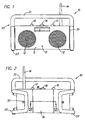
- The invention is now described with reference to the accompanying figures, wherein like numerals designate like parts. Referring to FIGS. 1-3, an audio equipment component, such as
radio 10, of the present invention comprises ahousing 11.Housing 11 may support the radio circuitry (not shown), thespeakers 12 connected to the radio circuitry, the volume, tuning and switch knobs (15, 16 and 17 respectively),antenna 14, andauxiliary input jack 13. - Preferably
speakers 12 and part ofhousing 11 are coated with a waterproof coating, such as a rubber coating or paint. Alternatively, other waterproofing schemes may be used for protecting thespeakers 12. For example, US Patent Nos. 3,391,754, 2,829,728, and 2,517,138 disclose appropriate waterproofing schemes and are hereby incorporated by reference. - The knobs may also comprise waterproofing means for impeding entry of water into
housing 11. Such means may include walls created on thehousing 11 and/or the knobs, creating a labyrinth passage for water. Alternatively, other waterproofing schemes may be used for the knobs. For example, US Patent Nos. 3,391,754, 3,277,739, 2,502,915 and 1,162,793 disclose appropriate waterproofing schemes and are hereby incorporated by reference. -
Antenna 14 is preferably constructed of a flexible material, allowingantenna 14 to bend without breaking. - Preferably, at least one protective covering, shield, or shell is flexibly connected to the
housing 11. An example of this protective covering isprotective bar 20. Such covering or shield, e.g.,bar 20, may be made of aluminum, or other suitable material. Preferably, covering or shield, e.g.,bar 20 is made of a plastic, such as ABS or polypropylene. The covering or shield, e.g.,bar 20, may be injection-molded. Alternatively, when the covering or shield is shaped as a bar, the plastic may be injected into a mold (preferably about half the volume needed to complete fill the mold and thus filling half of the mold), then air or gas is blown therein, pushing the plastic into the other half of the mold, forming a hollow tube. This process is known as gas-assist injection molding. - Preferably, the protective covering or shield is comprised of two
bars 20 which are formed in respective loops and are connected to a respective side ofhousing 11. The protective covering or shield may also include ahandle 21, which may be fixedly attached to thebars 20 via, e.g., screws (not shown). Preferably, the shape ofbars 20 and/orhandle 21 is such that thehousing 11 cannot be contacted by anything wider than thehandle 21 and/orbars 20. Such construction minimizes the risk of damage tohousing 11, but still allows access to the working components of the radio and/or does not muffle the sound produced by the speakers. - Persons skilled in the art will recognize that the protective shield or
bar 20 are preferably are releasably attached to the housing by coacting fasteners, such as screws, bolts, etc. By adapting protective shield orbar 20 in this manner, a user can replace parts of the protective shield or onebar 20 when damaged without incurring the expense of replacing entire shield, allbars 20 orradio 10. - As mentioned above, the protective shield or
bars 20 may be flexibly connected to the housing. Such connection is achieved via theconnector assemblies 30. Referring to FIG. 4, aconnector assembly 30 is disposed between thebar 20 andhousing 11. Theconnector assembly 30 comprises aflexible gasket 31, which is preferably made of a flexible, resilient material such as rubber or an elastometer. Thegasket 31 may be connected to thebar 20 via ascrew 34 threadedly engaging anut 35. Thegasket 31 in turn may be connected to thehousing 11 via ascrew 32 threadedly engaging anut 33.Gasket 31 may be molded overscrew 32 and/ornut 35. Such construction minimizes the shock received byhousing 11, and thus by the circuitry mounted within, whenradio 10 is dropped. - Referring to FIGS. 2 and 6,
housing 11 may also have adoor 19 pivotally attached thereto, providing access toreceptacle assembly 50 and allowing an operator to install abattery pack 60 withinhousing 11. Thedoor 19 may be kept in a closed position by latch 18. Preferably, latch 18 comprises an overcenter mechanism. -
Door 19 may have agasket 19G disposed thereon to limit the ingress of water into, if not wholly waterproof,receptacle assembly 50. Preferablygasket 19G is made of rubber or an elastomeric material. Persons skilled in the art will recognize that thegasket 19G may be disposed onhousing 11 and perform the same function. - Preferably,
receptacle assembly 50 is designed to receive abattery pack 60 via aconnector 56. Theconnector 56 has a configuration appropriate to contact the battery terminals. Preferably the battery pack terminals andconnector 56 will be arranged in the manner disclosed in U.S. Patent No. 5,144,217, which is hereby incorporated in whole by reference. - The
charger circuitry 43 may be fixedly connected to bothconnector 56 andreceptacle assembly 50.Connector 56 is preferably disposed on a floatingreceptacle housing 55, to minimize the shock received by thebattery pack 60 and thecircuitry 43 if theradio 10 is dropped.Charger circuitry 43 allows charging of battery packs having different voltages, as is well known in the art. - The
receptacle housing 55 may be flexibly connected to thehousing 11 via aflexible gasket 51. Preferably,gasket 51 is generally annular and made of a flexible, resilient material, such as rubber or elastometer. -
Retainers 52 may be installed onhousing 11 to prevent the disengagement ofgasket 51 and housing 11 when pushing thebattery pack 60 in place.Retainers 52 may be attached tohousing 11 viascrews 53 and may have a generally annular form.Retainers 52 may also prevent the removal ofreceptacle housing 55 when removing thebattery pack 60 by providing a stopping surface which would contact thecharger circuitry board 43. - A
spring 54 may also be provided ondoor 19 to biasbattery pack 60 into connection withconnector 56. Preferablyspring 54 will be flexible enough to bias battery packs having different sizes. - FIG. 5 is a block diagram of the circuitry within
housing 11.Charger circuitry 43 is connected to apower supply 40.Power supply 40 may receive power from an alternating current source viaconnector 41 and/or fromcharger 43 when a battery pack is being used as the power source for theradio 10. In addition,power supply 40 provides power tocharger 43 in order to chargebattery pack 60 even while theradio 10 is in operation. -
Power supply 40 also provides power toradio circuitry 44. A switching means 42 may be connected to switchknob 17 to properly select the components receiving power. For example, the user can select if the power supply 40: (a) provides power to both theradio circuitry 44 and to charger 43 (for charging battery pack 60); (b) provides power to theradio circuitry 44 from thebattery pack 60; (c) provides no power to any component; etc. Switching means 42 may comprise relays, transistors or other switching devices as is well known in the art. Preferablypower supply 40 can accept power from battery packs having different voltages. -
Radio circuitry 44 may comprise three main modules: (a)radio tuner 45 for receiving and demodulating the radio signal received viaantenna 14; (b)amplifier 46 connected totuner 45 for amplifying the demodulated radio signal; and (c)speakers 12 connected to amplifier 46 for converting the amplified signal into audible signals.Amplifier 46 may also amplify signals received from anauxiliary input 13, allowing a user to play a separate cassette deck or compact disk player through theradio 10. - Persons skilled in the art should recognize that the specific circuitry for each component is well known in the art. For example,
radio circuitry 44 may include an FM Front End integrated circuit, such as the Sanyo LA1186N used in a well-known manner, in combination with a low frequency power amplifier integrated circuit, such as the Toshiba TA8227P used in a well-known manner. Persons skilled in the art are referred to the specifications of these two integrated circuits for further information on the standard usage, capabilities, parameters, etc. - Moreover, the
radio circuitry 44 may be replaced with other circuitry for producing audio signals to the speakers via circuitry used with a cassette deck, compact disk or other methods to play music. - Preferably
charger 43 is shielded with a metal covering, such as lead, copper, gold, etc., so as to not affect the reception, processing and/or amplification of the radio signal. Similarly,charger 43 can be provided with induction coils, or other types of filters, so as to minimize the effect of the charger on the radio signal, etc. - With such construction, for example, a user can charge a battery pack by disposing the
battery pack 60 in thecharger 43, providing power to thebattery pack 60, and removing thebattery pack 60 from thecharger 43. Thebattery pack 60 can then be inserted into a power tool, such as drill 100 (FIG. 5). In other words, the user can listen to theradio 10 while charging thebattery pack 60. Alternatively, the user can manually switch thepower supply 40 so that theradio circuitry 43 receives the operating power from thebattery pack 60, rather than from the alternating current source. - Persons skilled in the art may recognize other alternatives to the means disclosed herein. However, all these additions and/or alterations are considered to be equivalents of the present invention.
Claims (19)
- Audio equipment comprising:a housing (11); andaudio circuitry (44) installed within the housing;
characterised in that a protective shield (20) is flexibly connected to the housing. - Audio equipment according to claim 1 wherein the protective shield is in the form of a bar (20).
- Audio equipment according to claim 1 or claim 2 further comprising a handle (21) attached to the protective shield.
- Audio equipment according to any one of claims 1 to 3, further comprising a connector assembly (30), which flexibly connects the protective shield to the housing.
- Audio equipment according to claim 4 wherein the connector assembly comprises a flexible gasket (31).
- Audio equipment according to claim 4 or claim 5 wherein the connector assembly is disposed between the protective shield and the housing.
- Audio equipment according to any one of claims 1 to 6, further comprising a second protective shield flexibly connected to the housing.
- Audio equipment according to claim 7 wherein the protective shields are comprised of two bars (20) which are formed in respective loops and are connected to a respective side of the housing.
- Audio equipment according to claim 8 having a protective shield further comprising a handle (21), which is fixedly attached to the bars (20).
- Audio equipment according to any one of the preceding claims further comprising:a power supply (40);a battery pack charger (43) connected to the power supply;a circuit (44) for producing an audio signal, preferably a radio circuit, connected to the power supply; anda battery pack (60) for use with a power tool, the battery pack removably connected to the battery pack charger for charging.
- Audio equipment according to any one of the preceding claims additionally comprising a receptacle assembly (50) for receiving a battery flexibly connected to the main housing.
- Audio equipment according to claim 11, wherein the receptacle assembly comprises a receptacle housing (55) and a flexible gasket (51), preferably made of rubber or elastomer is disposed between the receptacle housing and the main housing.
- Audio equipment according to claim 12 wherein the receptacle assembly further comprises at least one retainer (52) disposed on the housing to prevent disengagement of the gasket.
- Audio equipment according to any one of claims 11 to 13, further comprising a door (19) hingably connected to the main housing and opposite of the receptacle assembly.
- Audio equipment according to claim 14, wherein the door has a spring (54) disposed thereon to bias a battery disposed in the receptacle assembly towards a connecting position.
- Audio equipment according to any one of the preceding claims wherein the audio circuit is a radio circuit.
- Audio equipment according to any one of the preceding claims, comprising:a charger (43) disposed within the housing;a receptacle (50) in the charger;a battery pack (60) detachably connectable in a power tool mounted in the receptacle;a first electrical circuit in the charger for charging the battery pack and for powering the audio circuit; anda connector for connecting the first electrical circuit to a power source.
- Audio equipment according to claim 17 wherein the connector is adapted for connection to an AC power source, and the equipment further comprises a second electrical circuit connectable to the battery pack for powering the audio circuitry when the connector is disconnected from an AC power source.
- A method of manufacturing audio equipment as claimed in any one of the preceding claims, comprising:making a housing (11);providing a first protective shield (20);flexibly connecting the first protective shield to the housing.
Applications Claiming Priority (5)
| Application Number | Priority Date | Filing Date | Title |
|---|---|---|---|
| US15362198A | 1998-09-15 | 1998-09-15 | |
| US153621 | 1998-09-15 | ||
| US09/262,751 US6427070B1 (en) | 1999-03-04 | 1999-03-04 | Heavy-duty audio equipment |
| US262751 | 1999-03-04 | ||
| EP99307059A EP0987783B1 (en) | 1998-09-15 | 1999-09-06 | Battery powered portable heavy duty audio equipment |
Related Parent Applications (1)
| Application Number | Title | Priority Date | Filing Date |
|---|---|---|---|
| EP99307059A Division EP0987783B1 (en) | 1998-09-15 | 1999-09-06 | Battery powered portable heavy duty audio equipment |
Publications (3)
| Publication Number | Publication Date |
|---|---|
| EP1233664A2 EP1233664A2 (en) | 2002-08-21 |
| EP1233664A3 EP1233664A3 (en) | 2004-12-01 |
| EP1233664B1 true EP1233664B1 (en) | 2006-01-11 |
Family
ID=26850710
Family Applications (3)
| Application Number | Title | Priority Date | Filing Date |
|---|---|---|---|
| EP02006757A Revoked EP1233664B1 (en) | 1998-09-15 | 1999-09-06 | Rechargeable battery powered portable heavy duty audio equipment |
| EP99307059A Expired - Lifetime EP0987783B1 (en) | 1998-09-15 | 1999-09-06 | Battery powered portable heavy duty audio equipment |
| EP02006758.3A Expired - Lifetime EP1233665B2 (en) | 1998-09-15 | 1999-09-06 | Rechargeable battery powered portable heavy duty audio equipment |
Family Applications After (2)
| Application Number | Title | Priority Date | Filing Date |
|---|---|---|---|
| EP99307059A Expired - Lifetime EP0987783B1 (en) | 1998-09-15 | 1999-09-06 | Battery powered portable heavy duty audio equipment |
| EP02006758.3A Expired - Lifetime EP1233665B2 (en) | 1998-09-15 | 1999-09-06 | Rechargeable battery powered portable heavy duty audio equipment |
Country Status (12)
| Country | Link |
|---|---|
| EP (3) | EP1233664B1 (en) |
| JP (2) | JP3851029B2 (en) |
| CN (2) | CN100394698C (en) |
| AT (3) | ATE315887T1 (en) |
| DE (3) | DE69928579T3 (en) |
| DK (3) | DK0987783T3 (en) |
| ES (1) | ES2183487T3 (en) |
| HK (1) | HK1066349A1 (en) |
| ID (1) | ID23762A (en) |
| MY (1) | MY121364A (en) |
| PT (1) | PT987783E (en) |
| TW (1) | TW432810B (en) |
Families Citing this family (16)
| Publication number | Priority date | Publication date | Assignee | Title |
|---|---|---|---|---|
| CN101262080B (en) * | 2001-11-09 | 2010-11-10 | 密尔沃基电动工具公司 | Battery charger and electronic element using power tool battery |
| US7609027B2 (en) | 2001-11-09 | 2009-10-27 | Milwaukee Electric Tool Corporation | Electrical component, audio component, or electrical combination having a selectively connectable battery charger |
| US7332889B2 (en) | 2001-11-09 | 2008-02-19 | Milwaukee Electric Tool Corporation | Battery charger |
| US8604752B2 (en) | 2003-10-14 | 2013-12-10 | Robert Bosch Gmbh | Portable battery charging and audio unit |
| US7835534B2 (en) | 2003-10-14 | 2010-11-16 | Robert Bosch Gmbh | Battery charging jobsite lunchbox |
| US20050078834A1 (en) * | 2003-10-14 | 2005-04-14 | Credo Technology Corporation | Portable battery charging and audio unit |
| JP4624740B2 (en) * | 2004-08-26 | 2011-02-02 | 株式会社マキタ | Power tool storage case |
| US7741809B2 (en) | 2006-01-06 | 2010-06-22 | Milwaukee Electric Tool Corporation | Electrical component including a battery receptacle for including a battery |
| DE102008035766A1 (en) | 2008-07-31 | 2010-02-04 | Metabowerke Gmbh | Radio device for use in battery pack of cordless screwdriver, has housing and contact arrangement designed such that device is connected and operated with charging device for battery pack for electrical hand-tool device |
| JP5634740B2 (en) * | 2010-04-28 | 2014-12-03 | 株式会社マキタ | Electrical equipment system |
| JP5670839B2 (en) * | 2011-06-30 | 2015-02-18 | 株式会社マキタ | radio |
| DE102012203485A1 (en) | 2012-03-06 | 2013-09-12 | Robert Bosch Gmbh | Construction site radio device |
| JP6143086B2 (en) * | 2013-06-14 | 2017-06-07 | 日立工機株式会社 | Electrical equipment |
| US9693470B2 (en) | 2013-06-14 | 2017-06-27 | Hitachi Koki Co., Ltd. | Electric device with surrounding protective frame |
| JP2015192565A (en) * | 2014-03-28 | 2015-11-02 | 日立工機株式会社 | Charging apparatus and electric power supply |
| US11411278B2 (en) * | 2019-03-01 | 2022-08-09 | Milwaukee Electric Tool Corporation | Power tool and battery pack for use with the same |
Family Cites Families (14)
| Publication number | Priority date | Publication date | Assignee | Title |
|---|---|---|---|---|
| US3971889A (en) * | 1974-04-22 | 1976-07-27 | Hays Robert A | Portable bar adapted for mounting electronic equipment |
| US4050493A (en) * | 1976-01-05 | 1977-09-27 | Jin Sul Cho | Ladies handbag and radio |
| US4089044A (en) * | 1977-03-15 | 1978-05-09 | Motorola, Inc. | Housing assembly for miniaturized battery operated electrical apparatus |
| US4225970A (en) * | 1978-11-24 | 1980-09-30 | Motorola, Inc. | Splash proof portable two-way data terminal/radio |
| US4709201A (en) * | 1985-10-24 | 1987-11-24 | General Electric Company | Portable radio battery pack with on-off switch |
| DE3786170T2 (en) * | 1987-10-06 | 1993-09-23 | Black & Decker Inc | BATTERY KIT. |
| US5002184A (en) * | 1989-06-12 | 1991-03-26 | Grid Systems Corporation | Soft case protection for a hand held computer |
| US5090562A (en) * | 1991-04-23 | 1992-02-25 | Grullemans Winslow C | Protective case for portable sound-playing device |
| US5424725A (en) * | 1993-02-25 | 1995-06-13 | Motorola, Inc. | Battery retainer with integral mechanical shock isolation |
| US5680026A (en) * | 1994-03-21 | 1997-10-21 | Tyton Corporation | Tool belt with battery assembly |
| US5606241A (en) * | 1994-08-22 | 1997-02-25 | Motorola, Inc. | Apparatus for determining radio state during charging in order to provide charge compensation |
| ES2112212B1 (en) * | 1996-05-21 | 1998-11-16 | Maier S Coop Ltda | PROTECTIVE GUARD FOR A MOBILE PHONE. |
| CN2260288Y (en) * | 1996-05-24 | 1997-08-20 | 青岛海尔冷冻设备有限公司 | Protective rod of refrigerator |
| US6007940A (en) * | 1997-11-26 | 1999-12-28 | Celgard Llc | Portable power tool having low rate, rechargeable batteries |
-
1999
- 1999-08-14 MY MYPI99003496A patent/MY121364A/en unknown
- 1999-09-06 AT AT02006757T patent/ATE315887T1/en active
- 1999-09-06 AT AT99307059T patent/ATE228271T1/en not_active IP Right Cessation
- 1999-09-06 PT PT99307059T patent/PT987783E/en unknown
- 1999-09-06 EP EP02006757A patent/EP1233664B1/en not_active Revoked
- 1999-09-06 EP EP99307059A patent/EP0987783B1/en not_active Expired - Lifetime
- 1999-09-06 DE DE69928579.8T patent/DE69928579T3/en not_active Expired - Lifetime
- 1999-09-06 DE DE69929368T patent/DE69929368T2/en not_active Revoked
- 1999-09-06 ES ES99307059T patent/ES2183487T3/en not_active Expired - Lifetime
- 1999-09-06 EP EP02006758.3A patent/EP1233665B2/en not_active Expired - Lifetime
- 1999-09-06 AT AT02006758T patent/ATE311093T1/en not_active IP Right Cessation
- 1999-09-06 DK DK99307059T patent/DK0987783T3/en active
- 1999-09-06 DK DK02006757T patent/DK1233664T3/en active
- 1999-09-06 DK DK02006758T patent/DK1233665T3/en active
- 1999-09-06 DE DE69904005T patent/DE69904005T2/en not_active Expired - Lifetime
- 1999-09-07 TW TW088115405A patent/TW432810B/en not_active IP Right Cessation
- 1999-09-08 CN CNB2004100346379A patent/CN100394698C/en not_active Expired - Fee Related
- 1999-09-08 CN CNB991185552A patent/CN1162039C/en not_active Expired - Fee Related
- 1999-09-10 JP JP25746399A patent/JP3851029B2/en not_active Expired - Fee Related
- 1999-09-14 ID IDP990863D patent/ID23762A/en unknown
-
2004
- 2004-11-24 HK HK04109262A patent/HK1066349A1/en not_active IP Right Cessation
-
2006
- 2006-05-29 JP JP2006148847A patent/JP4417923B2/en not_active Expired - Fee Related
Also Published As
Similar Documents
| Publication | Publication Date | Title |
|---|---|---|
| US7466974B2 (en) | Heavy-duty audio equipment | |
| JP4417923B2 (en) | High durability audio device | |
| USRE44557E1 (en) | Ruggedized tradesworkers radio | |
| CN101194405B (en) | Portable battery charging and audio unit | |
| EP1685929A1 (en) | Tool storage case | |
| EP1744386B1 (en) | Combination device comprising a radio, audio device and battery charger. | |
| US8203307B2 (en) | Audio and charging system with audio device, power tool battery, and external battery charger | |
| EP2124475B1 (en) | Battery charging jobsite audio apparatus | |
| CN1848516B (en) | Electrical component, such as a radio, audio component, battery charger or radio/charger | |
| CN101257317A (en) | Heavy-duty audio equipment | |
| GB2410619A (en) | Electrical appliance with detachable battery charger | |
| GB2419472A (en) | Electrical appliance with detachable battery charger |
Legal Events
| Date | Code | Title | Description |
|---|---|---|---|
| PUAI | Public reference made under article 153(3) epc to a published international application that has entered the european phase |
Free format text: ORIGINAL CODE: 0009012 |
|
| 17P | Request for examination filed |
Effective date: 20020325 |
|
| AC | Divisional application: reference to earlier application |
Ref document number: 987783 Country of ref document: EP |
|
| AK | Designated contracting states |
Kind code of ref document: A2 Designated state(s): AT BE CH CY DE DK ES FI FR GB GR IE IT LI LU MC NL PT SE |
|
| PUAL | Search report despatched |
Free format text: ORIGINAL CODE: 0009013 |
|
| AK | Designated contracting states |
Kind code of ref document: A3 Designated state(s): AT BE CH CY DE DK ES FI FR GB GR IE IT LI LU MC NL PT SE |
|
| RIC1 | Information provided on ipc code assigned before grant |
Ipc: 7A 45F 5/02 B Ipc: 7H 05K 5/00 A Ipc: 7H 04B 1/08 B |
|
| RTI1 | Title (correction) |
Free format text: RECHARGEABLE BATTERY POWERED PORTABLE HEAVY DUTY AUDIO EQUIPMENT |
|
| RIC1 | Information provided on ipc code assigned before grant |
Ipc: 7H 05K 5/02 A Ipc: 7H 04B 1/38 B |
|
| GRAP | Despatch of communication of intention to grant a patent |
Free format text: ORIGINAL CODE: EPIDOSNIGR1 |
|
| RIC1 | Information provided on ipc code assigned before grant |
Ipc: 7H 05K 5/02 A Ipc: 7H 04B 1/38 B |
|
| AKX | Designation fees paid |
Designated state(s): AT BE CH CY DE DK ES FI FR GB GR IE IT LI LU MC NL PT SE |
|
| GRAS | Grant fee paid |
Free format text: ORIGINAL CODE: EPIDOSNIGR3 |
|
| GRAA | (expected) grant |
Free format text: ORIGINAL CODE: 0009210 |
|
| AC | Divisional application: reference to earlier application |
Ref document number: 0987783 Country of ref document: EP Kind code of ref document: P |
|
| AK | Designated contracting states |
Kind code of ref document: B1 Designated state(s): AT BE CH CY DE DK ES FI FR GB GR IE IT LI LU MC NL PT SE |
|
| PG25 | Lapsed in a contracting state [announced via postgrant information from national office to epo] |
Ref country code: IT Free format text: LAPSE BECAUSE OF FAILURE TO SUBMIT A TRANSLATION OF THE DESCRIPTION OR TO PAY THE FEE WITHIN THE PRESCRIBED TIME-LIMIT;WARNING: LAPSES OF ITALIAN PATENTS WITH EFFECTIVE DATE BEFORE 2007 MAY HAVE OCCURRED AT ANY TIME BEFORE 2007. THE CORRECT EFFECTIVE DATE MAY BE DIFFERENT FROM THE ONE RECORDED. Effective date: 20060111 Ref country code: FI Free format text: LAPSE BECAUSE OF FAILURE TO SUBMIT A TRANSLATION OF THE DESCRIPTION OR TO PAY THE FEE WITHIN THE PRESCRIBED TIME-LIMIT Effective date: 20060111 |
|
| REG | Reference to a national code |
Ref country code: CH Ref legal event code: EP |
|
| REG | Reference to a national code |
Ref country code: IE Ref legal event code: FG4D |
|
| REF | Corresponds to: |
Ref document number: 69929368 Country of ref document: DE Date of ref document: 20060406 Kind code of ref document: P |
|
| REG | Reference to a national code |
Ref country code: DK Ref legal event code: T3 |
|
| PG25 | Lapsed in a contracting state [announced via postgrant information from national office to epo] |
Ref country code: ES Free format text: LAPSE BECAUSE OF FAILURE TO SUBMIT A TRANSLATION OF THE DESCRIPTION OR TO PAY THE FEE WITHIN THE PRESCRIBED TIME-LIMIT Effective date: 20060422 |
|
| REG | Reference to a national code |
Ref country code: CH Ref legal event code: NV Representative=s name: E. BLUM & CO. PATENTANWAELTE |
|
| REG | Reference to a national code |
Ref country code: SE Ref legal event code: TRGR |
|
| PG25 | Lapsed in a contracting state [announced via postgrant information from national office to epo] |
Ref country code: PT Free format text: LAPSE BECAUSE OF FAILURE TO SUBMIT A TRANSLATION OF THE DESCRIPTION OR TO PAY THE FEE WITHIN THE PRESCRIBED TIME-LIMIT Effective date: 20060612 |
|
| ET | Fr: translation filed | ||
| PG25 | Lapsed in a contracting state [announced via postgrant information from national office to epo] |
Ref country code: IE Free format text: LAPSE BECAUSE OF NON-PAYMENT OF DUE FEES Effective date: 20060906 |
|
| PG25 | Lapsed in a contracting state [announced via postgrant information from national office to epo] |
Ref country code: MC Free format text: LAPSE BECAUSE OF NON-PAYMENT OF DUE FEES Effective date: 20060930 |
|
| PLBI | Opposition filed |
Free format text: ORIGINAL CODE: 0009260 |
|
| PLAX | Notice of opposition and request to file observation + time limit sent |
Free format text: ORIGINAL CODE: EPIDOSNOBS2 |
|
| 26 | Opposition filed |
Opponent name: MILWAUKEE ELECTRIC TOOL CORPORATION Effective date: 20061011 Opponent name: ROBERT BOSCH GMBH ZGM3 SPALDING Effective date: 20061011 |
|
| NLR1 | Nl: opposition has been filed with the epo |
Opponent name: MILWAUKEE ELECTRIC TOOL CORPORATION Opponent name: ROBERT BOSCH GMBH ZGM3 SPALDING |
|
| PLAF | Information modified related to communication of a notice of opposition and request to file observations + time limit |
Free format text: ORIGINAL CODE: EPIDOSCOBS2 |
|
| PLBB | Reply of patent proprietor to notice(s) of opposition received |
Free format text: ORIGINAL CODE: EPIDOSNOBS3 |
|
| REG | Reference to a national code |
Ref country code: CH Ref legal event code: PFA Owner name: BLACK & DECKER INC. Free format text: BLACK & DECKER INC.#DRUMMOND PLAZA OFFICE PARK 1423 KIRKWOOD HIGHWAY#NEWARK, DE 19711 (US) -TRANSFER TO- BLACK & DECKER INC.#DRUMMOND PLAZA OFFICE PARK 1423 KIRKWOOD HIGHWAY#NEWARK, DE 19711 (US) |
|
| PG25 | Lapsed in a contracting state [announced via postgrant information from national office to epo] |
Ref country code: GR Free format text: LAPSE BECAUSE OF FAILURE TO SUBMIT A TRANSLATION OF THE DESCRIPTION OR TO PAY THE FEE WITHIN THE PRESCRIBED TIME-LIMIT Effective date: 20060412 |
|
| PG25 | Lapsed in a contracting state [announced via postgrant information from national office to epo] |
Ref country code: LU Free format text: LAPSE BECAUSE OF NON-PAYMENT OF DUE FEES Effective date: 20060906 |
|
| PGFP | Annual fee paid to national office [announced via postgrant information from national office to epo] |
Ref country code: CH Payment date: 20080930 Year of fee payment: 10 |
|
| PG25 | Lapsed in a contracting state [announced via postgrant information from national office to epo] |
Ref country code: CY Free format text: LAPSE BECAUSE OF FAILURE TO SUBMIT A TRANSLATION OF THE DESCRIPTION OR TO PAY THE FEE WITHIN THE PRESCRIBED TIME-LIMIT Effective date: 20060111 |
|
| PGFP | Annual fee paid to national office [announced via postgrant information from national office to epo] |
Ref country code: FR Payment date: 20080917 Year of fee payment: 10 Ref country code: AT Payment date: 20080820 Year of fee payment: 10 Ref country code: NL Payment date: 20080924 Year of fee payment: 10 |
|
| PGFP | Annual fee paid to national office [announced via postgrant information from national office to epo] |
Ref country code: DK Payment date: 20080929 Year of fee payment: 10 |
|
| PGFP | Annual fee paid to national office [announced via postgrant information from national office to epo] |
Ref country code: BE Payment date: 20081009 Year of fee payment: 10 |
|
| PLBP | Opposition withdrawn |
Free format text: ORIGINAL CODE: 0009264 |
|
| RDAE | Information deleted related to despatch of communication that patent is revoked |
Free format text: ORIGINAL CODE: EPIDOSDREV1 |
|
| RDAF | Communication despatched that patent is revoked |
Free format text: ORIGINAL CODE: EPIDOSNREV1 |
|
| PGFP | Annual fee paid to national office [announced via postgrant information from national office to epo] |
Ref country code: GB Payment date: 20090929 Year of fee payment: 11 |
|
| PGFP | Annual fee paid to national office [announced via postgrant information from national office to epo] |
Ref country code: SE Payment date: 20090929 Year of fee payment: 11 Ref country code: DE Payment date: 20090929 Year of fee payment: 11 |
|
| RDAG | Patent revoked |
Free format text: ORIGINAL CODE: 0009271 |
|
| STAA | Information on the status of an ep patent application or granted ep patent |
Free format text: STATUS: PATENT REVOKED |
|
| REG | Reference to a national code |
Ref country code: CH Ref legal event code: PL |
|
| 27W | Patent revoked |
Effective date: 20091129 |
|
| GBPR | Gb: patent revoked under art. 102 of the ep convention designating the uk as contracting state |
Effective date: 20091129 |
|
| PG25 | Lapsed in a contracting state [announced via postgrant information from national office to epo] |
Ref country code: CH Free format text: LAPSE BECAUSE OF THE APPLICANT RENOUNCES Effective date: 20060111 Ref country code: LI Free format text: LAPSE BECAUSE OF THE APPLICANT RENOUNCES Effective date: 20060111 |
|
| REG | Reference to a national code |
Ref country code: SE Ref legal event code: ECNC |